

Page 1
Compact Soldering Station
Ref. CDE-BA
INSTRUCTION MANUAL
www.jbctools.com
Page 2
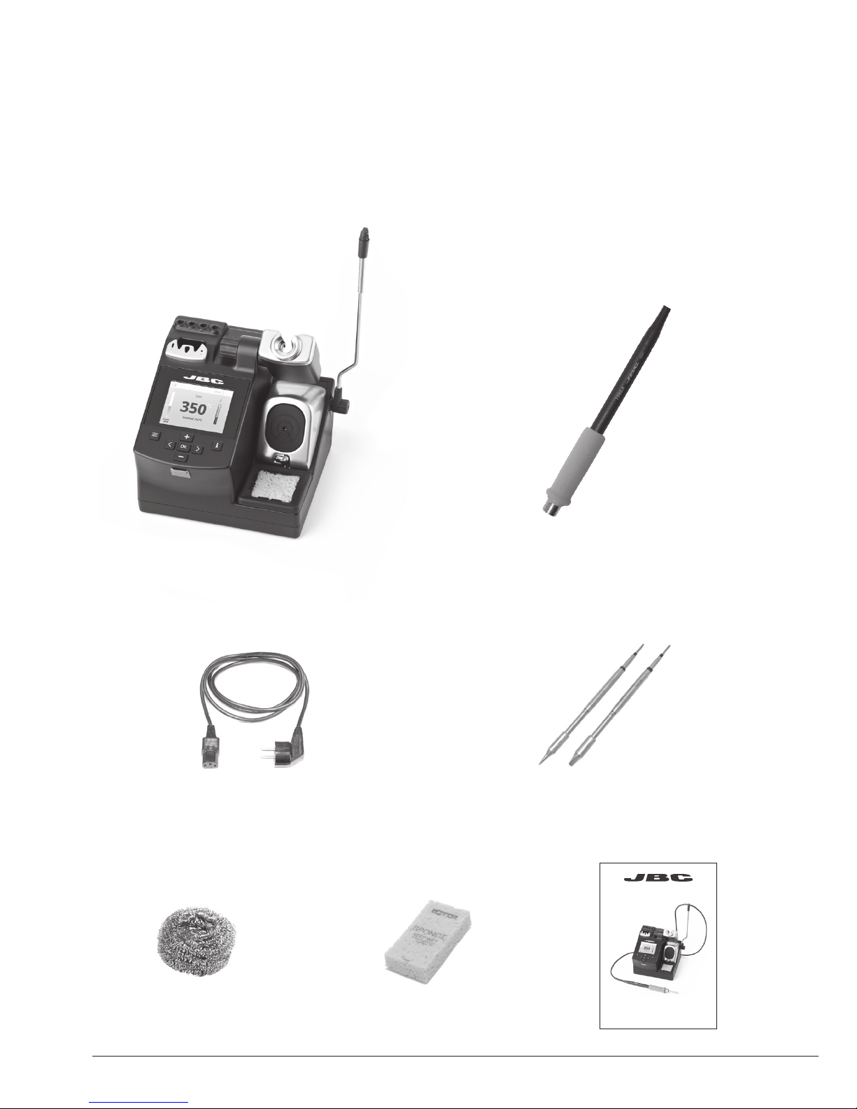
Packing List
The following items should be included:
Power Cord .................................................... 1 unit
Ref. 0009417 (100V/120V)
0009401 (230V)
Manual ............................... 1 unit
Ref. 0020588
CDE Control Unit .......................................... 1 unit
Ref. CDE-1BA (120V)
CDE-2BA (230V)
CDE-9BA (100V)
Brass Wool ....................... 1 unit
Ref. CL6210
Cartridges ................................................... 2 units
Ref. C245903 (x1)
C24 5 741 (x1)
Sponge ............................. 1 unit
Ref. S0354
General Purpose Handle ...................... 1 unit
Ref. T245-A
Compact Soldering Station
Ref. CDE-BA
www.jbctools.com
2
Page 3
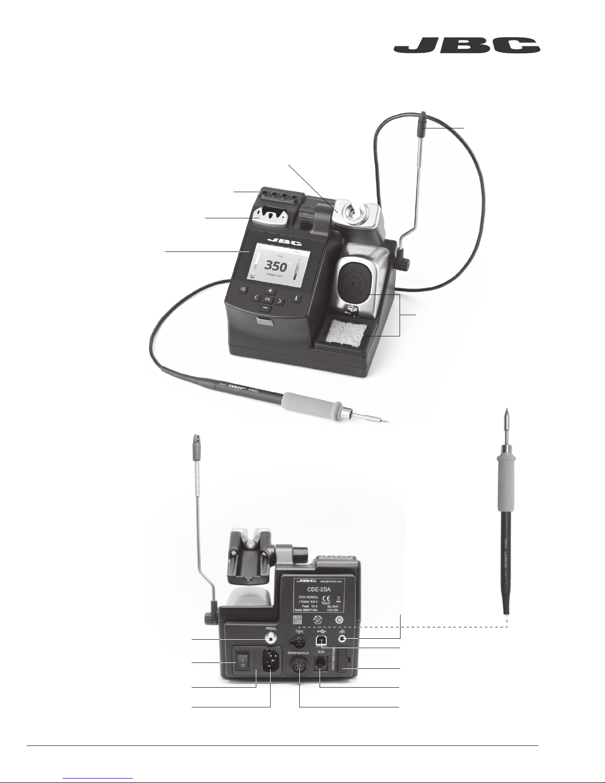
Earthing fuse
Aux connector
Equipotential connection
USB-B connector
PeripheralsPower Socket
Input Fuse
Main switch
Pedal connector
Features
General Purpose
Handle
Ref. T245-A
Cable collector
Quick Tip Changer
Cartridge storage
Tip Cleaner brass wool
with antisplash membrane
Process Screen
Adjustable Stand:
Intelligent Heat Management
www.jbctools.com
3
Page 4
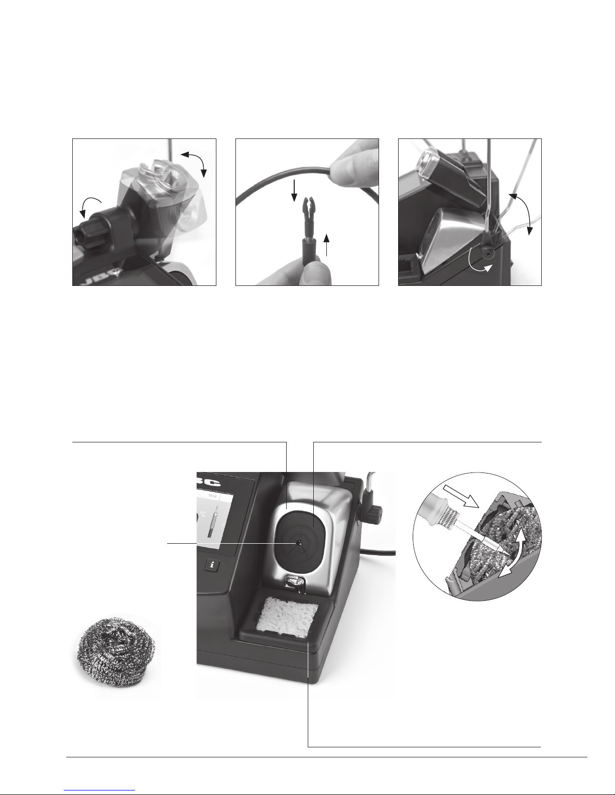
Brass Wool
Ref. CL6210
Very effective
cleaning method.
Leaves a small layer
of solder on the tip
preventing oxidation
between cleaning
and rewetting.
Adjustable stand Cable collector (Ref. CC3702)
Adjust the tool stand to suit
your work position.
Place the cable on the collector so that the working area is free
of cable.
Tip Cleaner
Select the option to suit your needs and improve the thermal transfer of the tip.
Splashguard
Ref. 0017576
It prevents splashing of solder particles
when using the brass wool.
Antisplash Membrane
Ref. 00175 74
Prevents splashing to maintain the work
area clean.
Wiper Ref. CL0160
A temperature resistant receptacle for removing
excess solder by gently tapping or wiping.
If the tip is very dirty,
JBC recommends first
cleaning it with the wiper
to remove excess solder.
4
Page 5
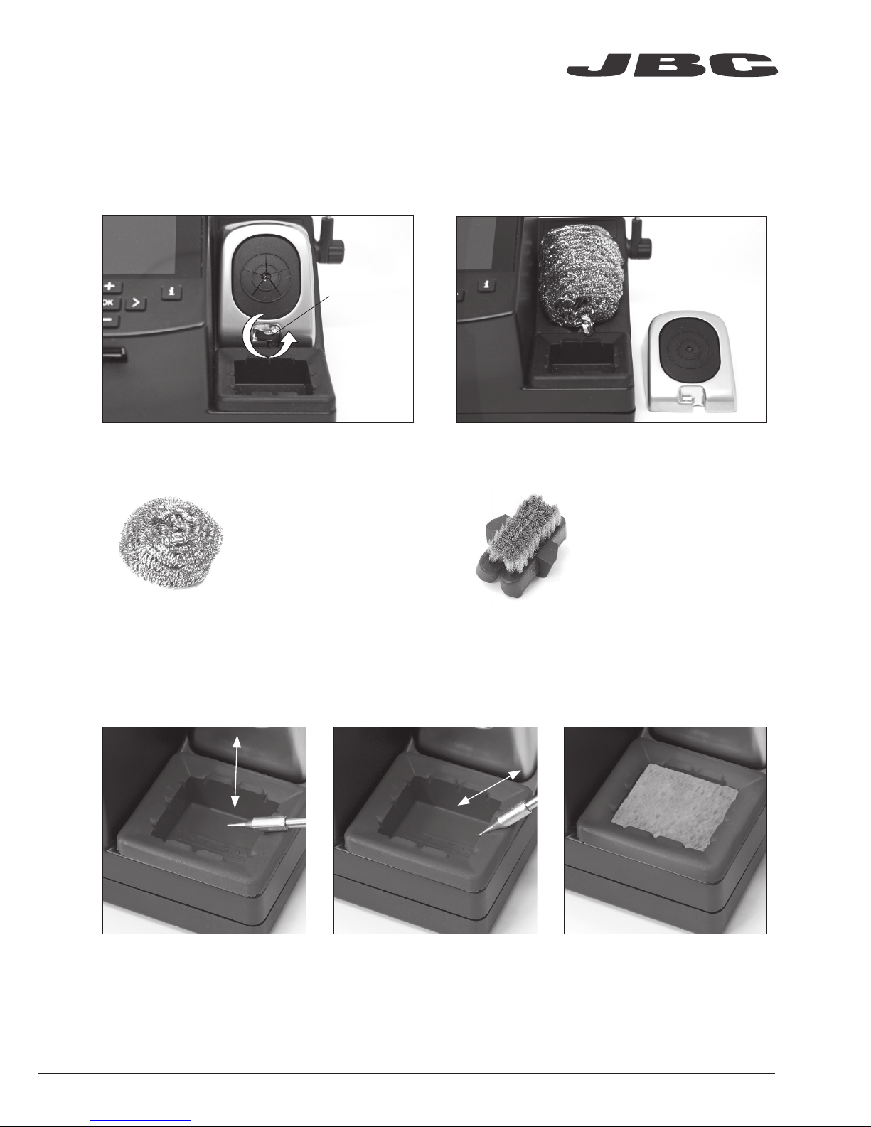
Lock
Removing the Splashguard
1. Unlock the splashguard.
2. Remove it.
More cleaning options (not supplied):
Inox Wool
Ref. CL6205
Provides a superior
cleaning of the tip.
Metal Brush
Ref. CL6220
When used carefully,
it provides a more
thorough cleaning.
Sponge
Ref. S0354
Tapping:
Tap gently to remove excess
solder.
Wiping:
Use the slots to remove
remaining particles.
Wiper
Ref. CL0160
The least harmful cleaning
method. Keep the sponge
damp with distilled water when
working to avoid tip wear.
www.jbctools.com
5
Page 6
ø 1
ø 3,5
A
B
B
C
A
Mark
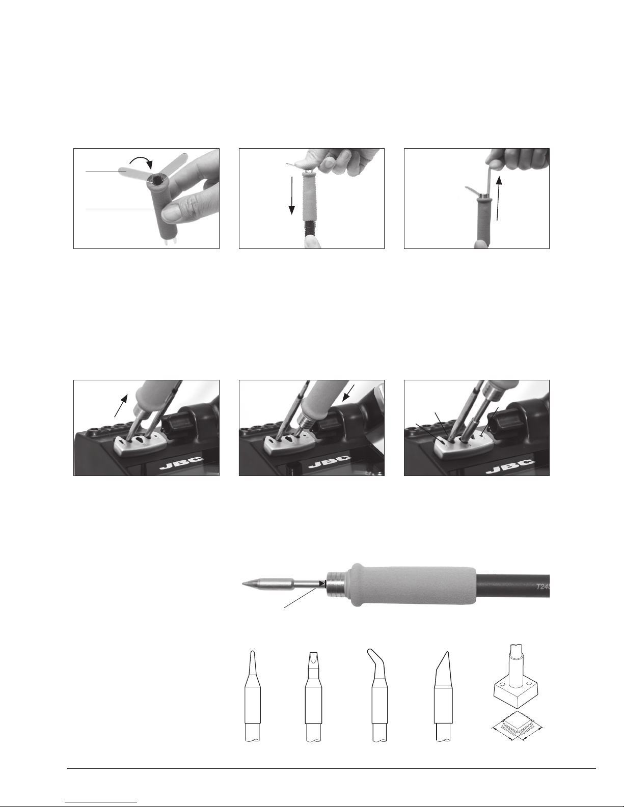
Changing the Grips
Easily replace the Grips for T245-A and T245-C using the slip-on tabs (Ref. 0016057)
1. Inserting tabs
2. Inserting handle
3. Removing tabs
Quick Tip Changer
Put the slide-on tabs into the
new grip.
Push the grip with the tabs
onto the handle.
To remove the tabs, hold the
grip and pull. Use a pliers if
necessary.
Save time and change cartridges safely without switching the station off.
1. Removing 2. Inserting
3. Fixing
Place the handpiece in the
extractor and pull to remove
the cartridge.
Place the handpiece on top
of the new cartridge and
press down slightly.
Use the holes for fixing the
cartridge* as follows:
A. For straight C210.
B. For curved C210.
C. For C245.
tabs
new grip
Round Chisel Round-bent Bevel Special models
Compatible cartridges
The CD-B stations work with
C245 cartridges.
Find the model that best
suits your soldering needs in
www.jbctools.com
*Important
It is essential to insert the
cartridges as far as the mark
for a proper connection.
6
Page 7

JBC
Updater
JBC
Manager
software
USB Connector
Download the latest software from our website to improve your soldering station.
JBC Updater
Update the station software via USB connection:
JBC Net
Remotely manage and monitor as many stations as your PC can handle.
Functions:
- Set all the station parameters from your PC.
- Organize groups of stations and set all their parameters at the same time.
- Store specific configurations for later uses.
- Analyze the soldering graphics of the stations on your PC and export them.
1. Download the JBC Manager software and the user manual from
www.jbctools.com/manager.html
2. Connect the stations via USB-B connector and the PC will automatically detect them.
3. The notification will be displayed on the station.
Cable USB AB
any JBC
station
USB Hub
Cable USB
AB
www.jbctools.com
7
Page 8

Long time in
the stand
350
ºC
Power
45%
T245
17:14
Selected 350ºC
T245
17:14
Sleep
Tool in the stand
Actual Temp. 180ºC
Delay to hibernation: 29:30
T245
17:14
Hibernation
Actual Temp. 25ºC
Operation
The JBC Exclusive Heating System
This revolutionary technology is able to recover tip temperature extremely quickly.
This allows the user to work at a lower temperature.
As a result, tip life increases up to 5.
1. Work 2. Sleep 3. Hibernation
When the tool is lifted from the
stand the tip will heat up to the
selected temperature.
When the tool is in the stand,
the temperature falls to the
preset sleep temperature.
After longer periods of
inactivity, the power is cut off
and the tool cools down to
room temperature.
Tools Menu:
· Set temperature limits
· Select temperature levels
Tools Menu:
· Set Sleep temperature
· Set Sleep delay
(from 0 to 9 min or no Sleep)
Tools Menu:
· Set Hibernation delay
(from 0 to 60 min or no
hibernation)
8
Page 9

350
ºC
Power
45%
Temp. Levels
T245
250 350 380
17:14
Tool
in use
Work Screen
Status bar
Displayed if
temperature
levels are
activated
Power
indicator
The CDE offers an intuitive user interface which provides quick access to station parameters.
Original PIN: 0105
Menu Options
Information
Change
port
Station Tools Counters
ResetGraphicsPeripherals
Press INFO for each parameter description. USB flash drive is connected.
Station is controlled by a PC.
Station is controlled by a robot.
Station software update.
Press INFO to start the process.
Warning.
Press INFO for failure description.
Error. Press INFO for failure description,
the type of error and how to proceed.
System notifications (Status Bar)
www.jbctools.com
9
Page 10

400
380
360
340
320
100
80
60
40
20
[ºC] Temp Power [%]
By pressing Graphics in the main MENU, temperature and power figures in real
time are displayed for each port. This helps you decide which tip to use to obtain
the best quality solder joints.
Process analysis
Graphics
Temperature
Power (%)
Export graphics
Insert a USB flash drive into the USB-A connector
to save your soldering process in csv format.
Change port
Information
Back
Change grid
Exit
10
Page 11

Station Settings
Minimum temperature
Set the minimum temperature
to work with.
Min. temp. by default is 200ºC
(392ºF). This is considered to
be a proper starting point for
leaded applications.
Maximum temperature
Set the maximum
temperature to work with.
Max. temp by default is 400°C
(750°F). This is considered
high enough to work with
most lead-free applications.
Temperature unit
Celsius (ºC) or Fahrenheit (ºF)
Recommendations Parameter description
N/a
Warnings
The station temperature
range is 90-450ºC
(190-840ºF). Change the
temperature limits when
working with less common
applications such as low / high
melting point soldering (HMP)
or plastics (e. g. riveting).
In most cases,
working with temperatures
over 400°C (750°F) can
damage the PCB and its
components. Even in short
time periods of tip contact
with the soldering joint, the
flux may not work properly
and could seriously reduce
tip life. If the solder joint
requires more power
(e.g. multilayered or high
dissipation boards), JBC
strongly recommends using
other aids like preheaters.
Be careful when using these parameters as they may reduce the tip life if not used properly.
Please follow the recommended guidelines:
Parameters
Help text
Activate this parameter to
receive info from the system.
Beep
Enable/disable the beep
sound of the keypad.
Change pin
Change the default security
PIN number (0105).
The PIN must be entered every
time a parameter is changed.
N/a
N/a
N/a
N/a
N/a
www.jbctools.com
11
Page 12

Sleep delay
Set the time that the tool
will remain at the selected
temperature when in the stand
before entering sleep mode.
The tip temperature will then
drop to the Sleep temperature.
Fix one temperature
Fix a value within the
temperature range of the
station (90-450ºC/190-840ºF).
Temperature levels set
Similar to “Fix one temp”
parameter. In this case, the
user can set up to 3 values for
different power requirements.
The sleep temperatures are
set to achieve a balance
between preventing oxidation
and reaching the working
temperature in a few seconds.
Ideal for soldering more than
one component at a specific
temperature. The station will
reject any attempt to change
the temperature.
This allows a quick change
between 3 different temperatures. Set them according
to the allowed values for your
soldering applications.
Because our tools reach the
working temperature from the
deafult Sleep mode in only a
few seconds, this parameter is
preset to 0 min. Once the tool
is returned to the stand the
temperature will automatically
drop to the sleep temperature,
extending tip life and avoiding
oxidation. Retinning the tip
before placing the tool in the
stand will protect the tip and
extend its life.
Recommendations Parameter description
Warnings
N/a
N/a
Setting these
parameters to higher values
will unnecessarily accelerate
oxidation and shorten tip
life especially when working
with temperatures up to
450°C (840°F).
Tool Settings
Sleep temperature
This is the set temperature the
tip reaches when returned to
the stand.
12
Page 13

Hibernation Delay
Set the time the tool will
remain at Sleep temperature
before entering the Hibernation
mode. At this time, the power
supply is cut off and the tip
remains at room temperature.
Tool Settings
Recommendations
Parameter description Warnings
Increasing the default
value will accelerate
oxidation and shorten the
tip life.
When the user changes
the cartridge type, the
parameter should be reset
to 0°C/F or to the value
needed for this cartridge.
E.g. If a correction of
+20°C (+36°F) is set for the
C245966 (thick type) and
then the user changes the
cartridge for a C245030
(which is thinner) without
resetting, they would be
working at a temperature
of +20°C (+36°F) lower for
the C245030 which does
not need any temperature
adjustment.
This function completely
protects the tip from oxidation
during long periods of
inactivity while the tool is in the
stand.
Retinning the tip before
placing the tool in the stand
also helps prevent oxidation
and extends the life of the tip.
Temp Adjustment
It provides a more precise
adjustment between the
selected temperature and the
actual one.
Set values within ±50°C
(± 90°F) to achieve zero error.
JBC strongly recommends
the use of TID-A or TIA-A
Thermometers to obtain
precise readings.
www.jbctools.com
13
Page 14

Clean
periodically
Before carrying out maintenance, always allow the equipment to cool.
- Clean the station screen with a glass cleaner or a damp cloth.
- Use a damp cloth to clean the casing and the
tool. Alcohol can only be used to clean the
metal parts.
- Periodically check that the metal parts of the
tool and stand are clean so that the station
can detect the tool status.
- Maintain tip surface clean and tinned prior to
storage in order to avoid tip oxidation.
Rusty and dirty surfaces reduce heat transfer
to the solder joint.
- Periodically check all cables and tubes.
Maintenance
Replace the blown fuse as follows.
1. Pull off the fuse holder and remove the fuse. If necessary use a tool to lever it off.
2. Insert the new fuse into the fuse holder and return it to the station.
- Replace any defective or damaged pieces. Only use original JBC spare parts.
- Repairs should only be performed by a JBC authorized technical service.
*The Earthing Fuse minimize the risk of damaging the equipment when the tip touches a part with
an active voltage. If the Earthing Fuse is blown, the station will show a message indicating that the
fuse needs to be replaced.
Be aware that if the station keeps working in this conditions, the tip to ground resistance would not
meet the specifications.
Earthing Fuse *Imput Fuse
14
Page 15

It is imperative to follow safety guidelines to prevent electric
shock, injury, fire or explosion.
- Do not use the units for any purpose other than soldering or rework. Incorrect use may cause fire.
- The power cable must be plugged into approved bases. Make sure that it is properly grounded
before use. When unplugging it, hold the plug, not the wire.
- Do not work on electrically live parts.
- The tool should be placed in the stand when not in use in order to activate the sleep mode.
The soldering tip, the metal part of the tool and the stand may still be hot after the station
is turned off. Handle with care, including when adjusting the stand position.
- Do not leave the appliance unattended when it is on.
- Do not cover the ventilation grills. Heat can cause inflamable products to ignite.
- Avoid flux coming into contact with skin or eyes to prevent irritation.
- Be careful with the fumes produced when soldering.
- Keep your workplace clean and tidy. Wear appropriate protection glasses and gloves when
working to avoid personal harm.
- Utmost care must be taken with liquid tin waste which can cause burns.
- This appliance can be used by children over the age of eight as well as persons with reduced
physical, sensory or mental capabilities or lacking experience provided that they have been given
adequate supervision or instruction concerning use of the appliance and understand the hazards
involved. Children must not play with the appliance.
- Maintenance must not be carried out by children unless supervised.
Safety
www.jbctools.com
15
Page 16

产品中有害物质的名称及含量
有害物质含量表
部件名称
有害物质
铅(Pb) 汞(Hg) 镉(Cd)
六价铬
(Cr(VI))
多溴联苯
(PBB)
多溴二苯醚
(PBDE)
烙铁头 O O O O O O
手柄 O O O O O O
电源线 O O O O O O
主机 O O O O O O
电源插座 O O O O O O
保险丝 O O O O O O
主开关 O O O O O O
电位连接 X O O O O O
变压器 O O O O O O
线路板 X O O O O O
O 表示该有害物质在该部件所有均质材料中的含量均在GB/T 26572 规定的限量要求以下。
X 表示该有害物质至少在该部件的某一均质材料中的含量超出GB/T 26572 规定的限量要求。
16
Page 17

Exploded View
www.jbctools.com
17
Page 18

Notes
18
Page 19

www.jbctools.com
19
Page 20

This product should not be thrown in the garbage.
In accordance with the European directive 2002/96/EC, electronic equipment at the end of their life
must be collected and returned to an authorized recycling facility.
Manual in other languages available on our website
Warranty
JBC’s two-year warranty covers this equipment
against all manufacturing defects, including the
replacement of defective parts and labour. Warranty
does not cover product wear or misuse. In order for
the warranty to be valid, equipment must be returned,
postage paid, to the dealer where it was purchased.
Register your warranty within 30 days of purchase
in www.jbctools.com/productregistration
Specifications
CD E-1BA 120V 50/60Hz.
Input fuse: 2A. Earthing fuse: 1.25 A. Output: 23,5V. Control Unit model: CD E-1A
CDE-2BA 230V 50/60Hz.
Input fuse: 1A. Earthing fuse: 1.25 A. Output: 23,5V. Control Unit model: CDE-2A
CDE-9BA 100V 50/60Hz.
Input fuse: 2A. Earthing fuse: 1.25 A. Output: 23,5V. Control Unit model: CDE-9A
- Weight: 2,8 kg (6.17 lb)
- Dimensions: 150 x 175 x 145 mm (5.9 x 6.9 x 5.7 in)
- Output Peak Power CD-BE: 130W
- Temperature Range: 90 - 450 °C (190 - 840 °F) (±5%)
- Idle Temp. Stability (still air): ±1.5 ºC / ±3 ºF
- Tip to ground resistance: <2 ohms
- Tip to ground voltage: <2mV RMS
- Ambient operating temp: 10 - 40 ºC (50 - 104 ºF)
- USB connector station-PC
Complies with CE standards.
ESD protected housing.
00 2 0 588 -0 418
www.jbctools.com
 Loading...