

Page 1

Page
English 2
Español 20
Deutsch 38
中文 54
www.jbctools.com
Compact Soldering Station
Ref. CD-BE
Page 2

www.jbctools.com
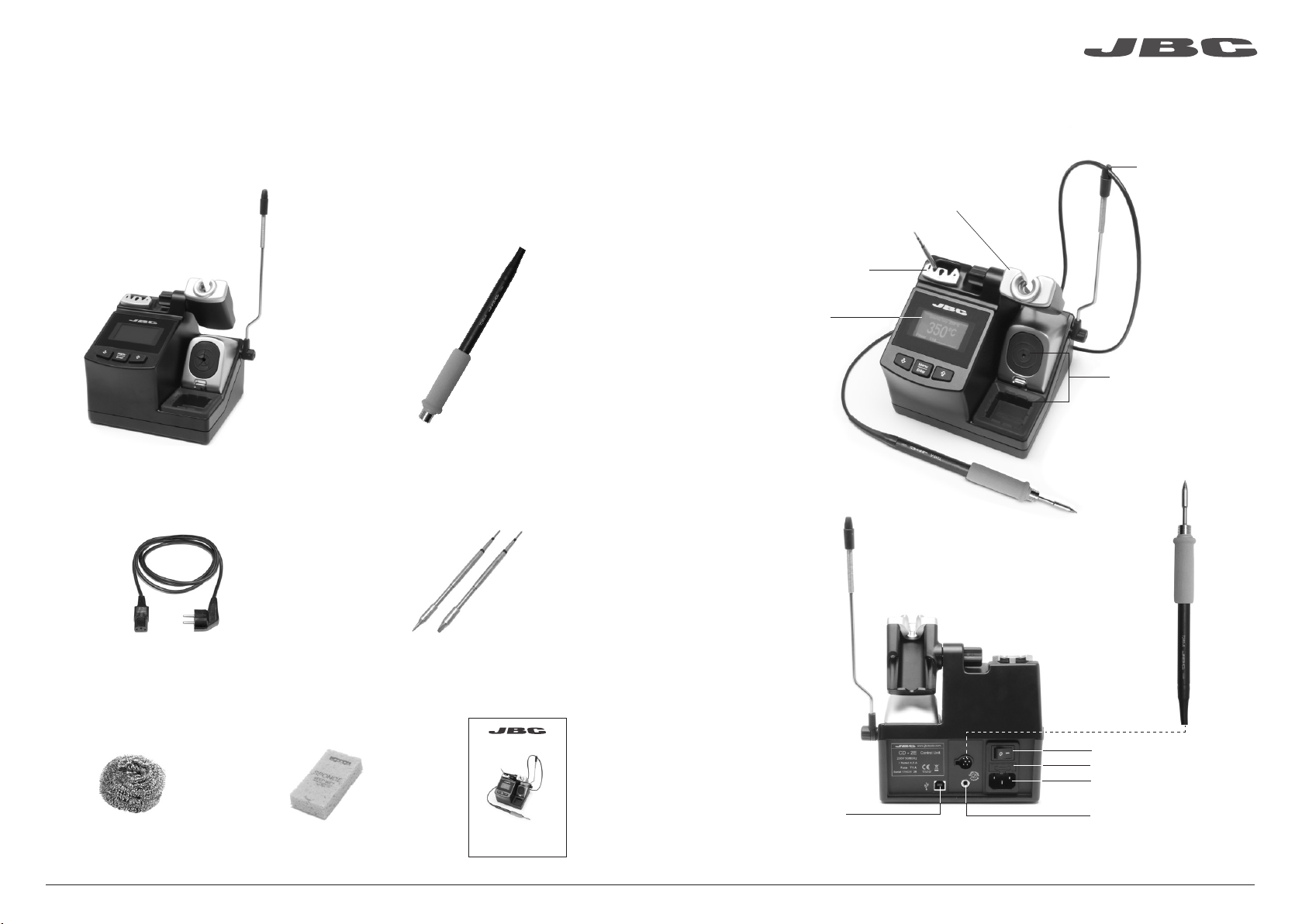
Packing List
The following items should be included:
CD Control Unit ..................................... 1 unit
Ref. CD-1E (120V)
CD-2E (230V)
CD-9E (100V)
Power Cord .............................................. 1 unit
Ref. 0009417 (100V/120V)
0009401 (230V)
General Purpose Handle ................. 1 unit
Ref. T245-A
Cartridges .............................................. 2 units
Ref. C245903 (x1)
C245741 (x1)
Features
Quick Tip Changer
Process
Screen
Adjustable Stand:
Intelligent Heat
Management
Cable collector
Tip Cleaner brass wool
with antisplash
membrane
General Purpose
Handle
Ref. T245-A
Brass Wool ................ 1 unit
Ref. CL6210
Sponge ....................... 1 unit
Ref. S0354
Manual ........................ 1 unit
Ref. 0017353
www.j bct ools .co m
Main switch
Fuse
Power Socket
Compact Soldering Station
Ref. CD-BE
USB-B connector
Equipotential connection
2 3
Page 3
www.jbctools.com
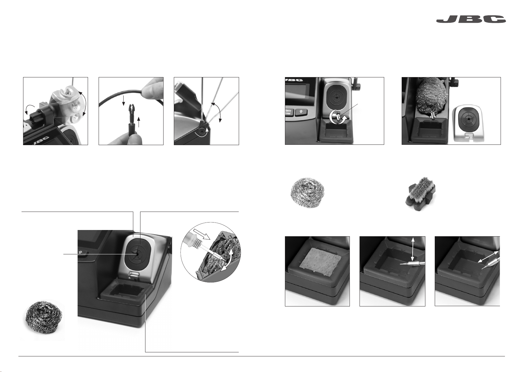
Adjustable stand Cable collector
Adjust the tool stand to suit
your work position.
Place the cable on the collector so that the working area is free
of cable.
(Ref. CC3702)
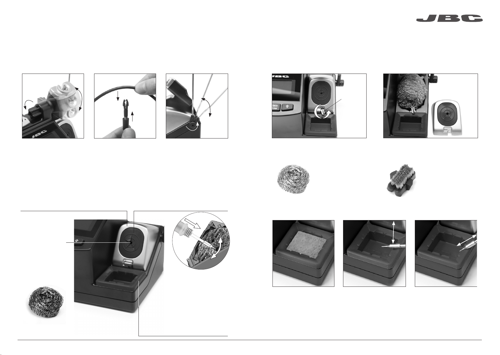
Tip Cleaner
Select the option to suit your needs and improve the thermal transfer of the tip.
Splashguard
Ref. 0017576
It prevents splashing of solder particles
when using the brass wool.
Antisplash Membrane
Ref. 0017574
Prevents splashing to maintain the work area
clean.
Removing the splashguard:
1. Unlock the splashguard. 2. Remove it.
Lock
More cleaning options (not supplied):
Inox Wool
Ref. CL6205
Provides a superior
cleaning of the tip.
Metal Brush
Ref. CL6220
When used carefully, it
provides a more thorough
cleaning.
Wiper
Brass Wool
Ref. CL6210
Very effective
cleaning method.
Leaves a small layer
of solder on the tip
preventing oxidation
between cleaning
and rewetting.
If the tip is very dirty,
JBC recommends first
cleaning it with the wiper
to remove excess solder.
Wiper
Ref. CL0160
A temperature resistant receptacle
for removing excess solder by gently
tapping or wiping.
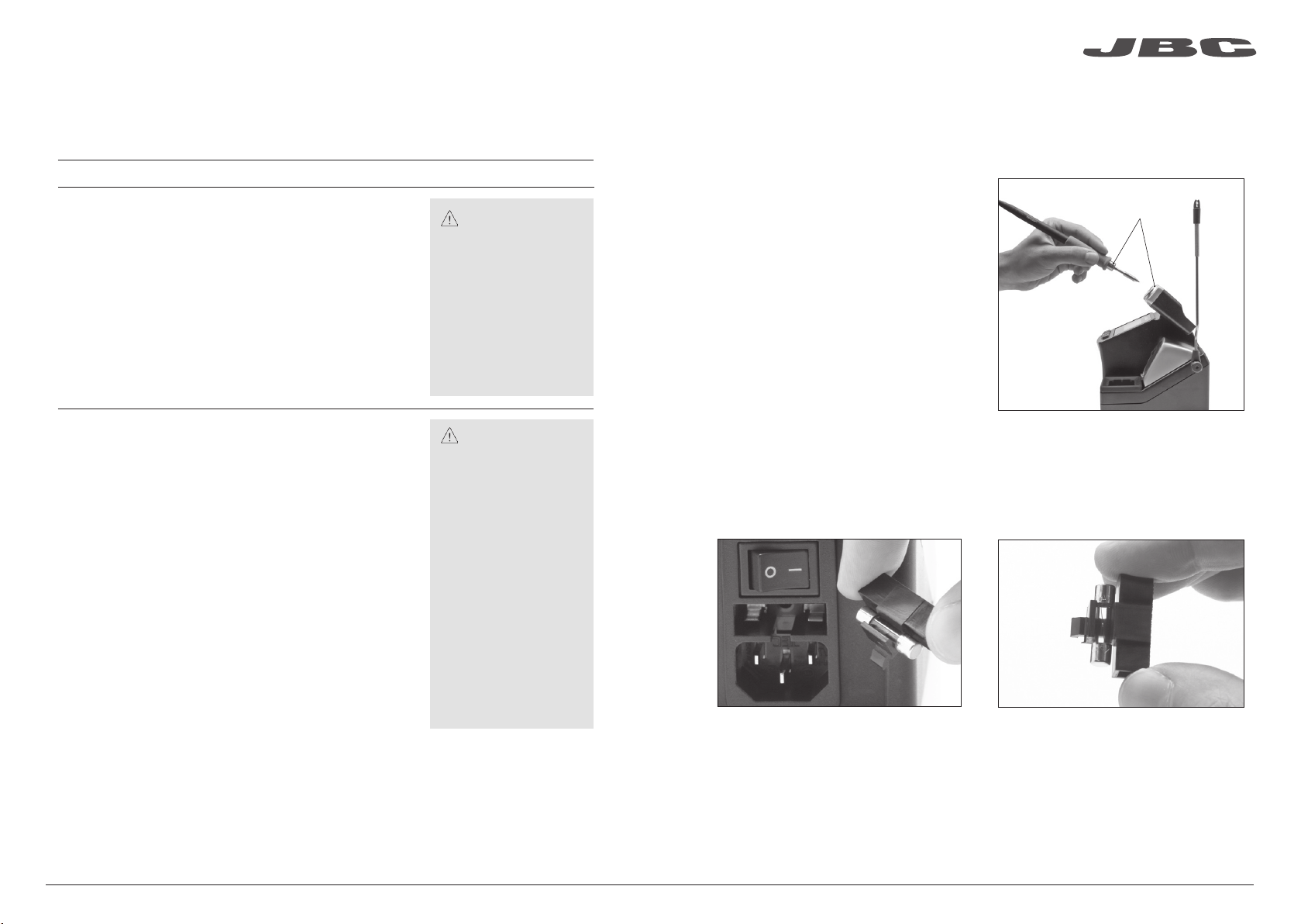
Sponge
Ref. S0354
The least harmful cleaning
method. Keep the sponge
damp with distilled water
when working to avoid tip
wear.
Tapping:
Tap gently to remove excess
solder.
Wiping:
Use the slots to remove
remaining particles.
4 5
Page 4
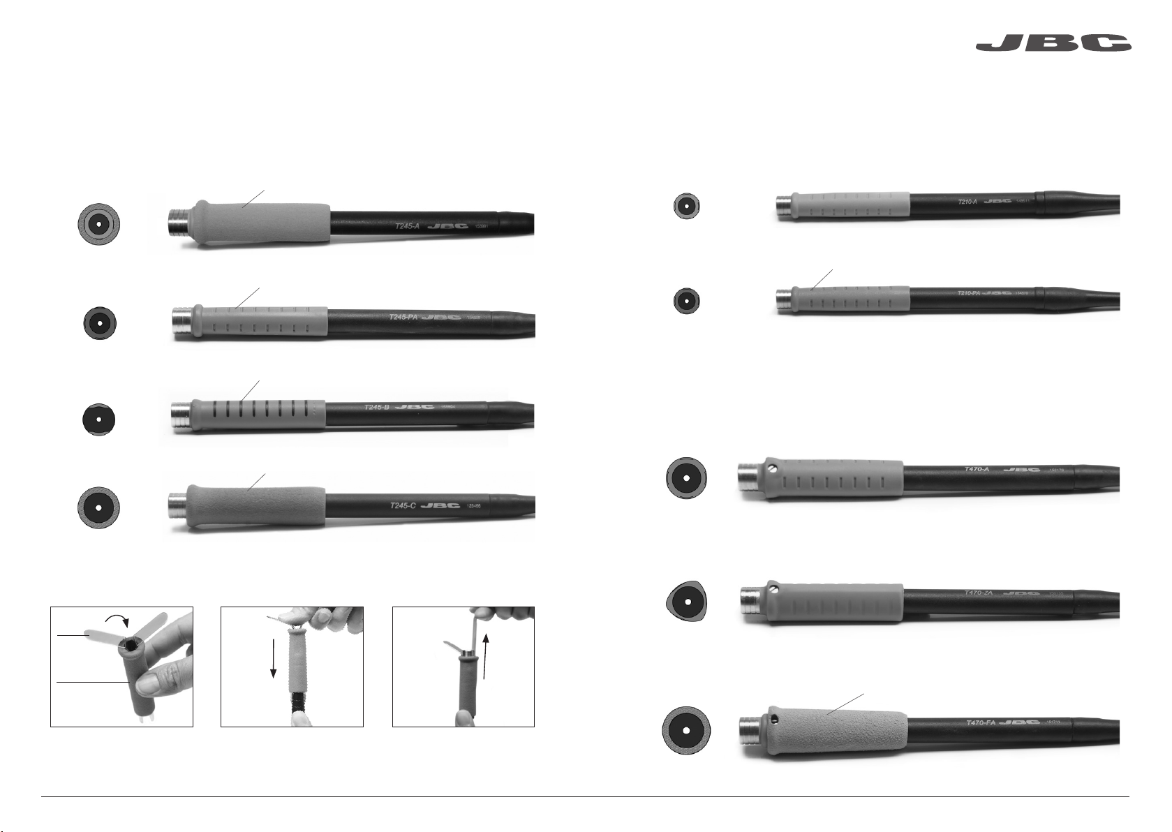
Compatible Handles
For general use
Works with C245 Cartridge range
General Purpose Handle
Ref. T245-A
www.jbctools.com
For precision use
Works with C210 Cartridge range
Precision Purpose Handle
Ref. T210-A
Soft foam (Ref. 0016057)
Blue Handle
Ref. T245-PA
Non-slip Handle
Ref. T245-B
Soft Thermal Insulator Handle
Ref. T245-C
Easily replace the Grips for T245-A and T245-C using the slip-on tabs (Ref. 0016057 Supplied with
4 grips).
1. Inserting tabs 2. Inserting handle
tabs
new grip
Blue grip to easily distinguish it from other handles
Non-slip soft touch
Soft foam (Ref. 0016057)
3. Removing tabs
Blue Precision Handle
Ref. T210-PA
Blue grip to easily distinguish it from other handles
For greater demands
Important: Only work with C245 cartridges when used with a CD station.
For intensive soldering jobs requiring continued high thermal power. They feature good thermal
insulation and a screw which fixes the cartridge and prevents its rotation.
HD Purpose Handle HD Purpose Handle + 3m cable
Ref. T470-A Ref. T470-SA
Tri-lobed HD Handle
Ref. T470-ZA
For better handling of the tool.
Thermal Insulator HD Handle Thermal Insulator HD Handle + 3m cable
Ref. T470-FA Ref. T470-MA
Foam
Put the slide-on tabs into the
new grip.
Push the grip with the tabs
onto the handle.
Note: All models are supplied with a 1.5 m cable.
To remove the tabs, hold the
grip and pull. Use a pliers if
necessary.
Note: All models are supplied with a 1.5 m cable except those specified with 3 m.
6 7
Page 5
ø 1
ø 1,5
ø 3,5
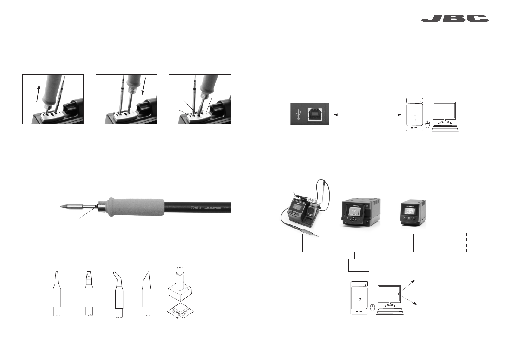
Quick Tip Changer
Save time and change cartridges safely without switching the station off.
www.jbctools.com
USB Connector
Download the latest software from our website to improve your soldering station.
1. Removing 2. Inserting 3. Fixing
C
B
Place the handpiece in the
extractor and pull to
remove the cartridge.
*Important
It is essential to insert the cartridges as far as the mark for a proper connection.
Mark
Place the handpiece on top
of the new cartridge and
press down slightly.
Use the holes for fixing the
cartridge* as follows:
A. For straight C210.
B. For curved C210.
C. For C245.
JBC Updater
www.jbctools.com/software.html
Update the station software via USB connection:
A
Cable USB AB
JBC
Updater
JBC Manager
www.jbctools.com/manager.html
Manage and monitor as many stations as your PC can handle by using the JBC Manager. You can
export data to another PC.
any JBC
station
Compatible cartridges
The CD stations work with C245 cartridges and T245/T470 handpieces or C210 cartridges with
T210 handpieces. Find the model that best suits your soldering needs in www.jbctools.com
Cable
USB AB
USB
Hub
Manager Settings
Change settings for a
group of JBC stations at
Round Chisel Round
bent
A
B
Bevel Special models
JBC
Manager
the same time.
Register Settings
Create graphs of the
soldering process in real
time with power and
temperature data.
8 9
Page 6
www.jbctools.com
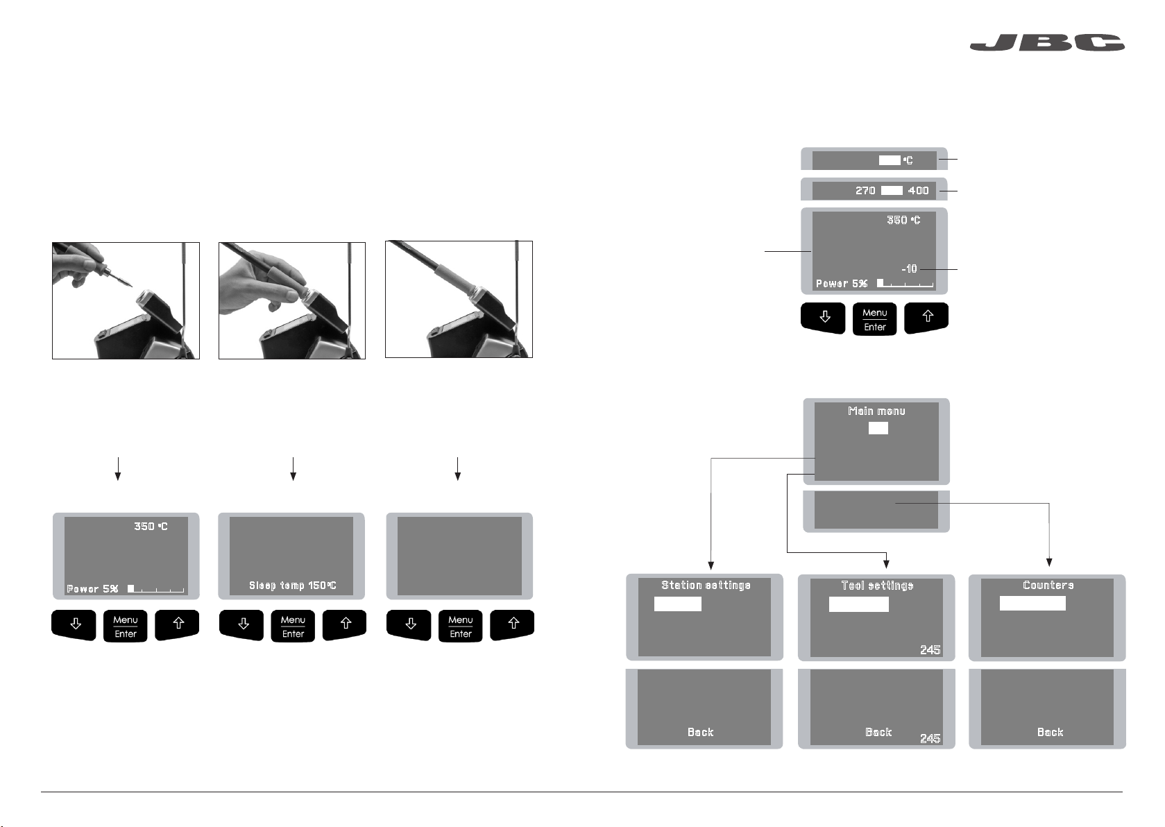
Operation
The JBC Exclusive Heating System
This revolutionary technology is able to recover tip temperature extremely quickly.
This allows the user to work at a lower temperature.
As a result, tip life increases up to 5.
1. Work
When the tool is lifted from the
stand the tip will heat up to the
selected temperature.
2. Sleep
When the tool is in the stand,
the temperature falls to the
preset sleep temperature.
3. Hibernation
Long time in
the stand
After longer periods of
inactivity, the power is cut off
and the tool cools down to
room temperature.
Control Process
Work Screen
The work screen provides
useful information of tool
status in real time.
Menu Screen
Original PIN: 0105
Fixed temp.
Levels ºC
Selected temp.
35 0 oC
27 0 3 50 40 0
35 0 oC
350
P o we r 5 %
Mai n me nu
Exit
1 Reset settings
Station settings
2
3
Tool settings
Displays a specific fixed temp.
Shown when you have
selected temp. levels. The
values must be adjusted
according to the work needs.
0
c
- 1 0
“Temp. Adjust” parameter.
It provides a more precise
adjustment between the
selected temp and the
actual one.
4 Counters
Program version
Selected temp
350
P o we r 5 %
· Change temperature
(from 90 to 450ºC)
· Select temperature levels
· Fix one temperature
35 0 oC
0
c
Sleep
0
c
350 350
S l ee p t em p 1 50oC
· Change Sleep temperature
· Set Sleep delay
(from 0 to 9 min or no Sleep)
Hibernation
0
c
To ol in the sta nd, no hea t
· Change Hibernation delay
(from 0 to 35 min)
Sta ti on s et ti ng s
1 Temp unit
2
Maximum temp 4000C
3
Minimum temp 2000C
4
Metronome ----
5 Help text OFF
6 Beep ON
7
Change PIN
Celsius
Bac k
5
Too l se tt in gs
1
Fix one temp -----
2
Temp levels set OFF
3
Sleep delay 0 min
Tool 245
4
Sleep temp 1500C
5
Hibernation delay 10 min
6
Temp adjust + O OC
Bac k
Tool 245
Cou nt er s
1
Plugged hours 0
2
Working hours 0
3
Sleep hours 0
4
Hibernation hours 0
5
No tool hours 0
6 Sleep cycles
0
Bac k
10 11
Page 7

Parameters
Be careful when using these parameters as they may reduce the tip life if not used properly. Please
follow the recommended guidelines:
www.jbctools.com
Station Settings
Parameter description
Temperature unit
Celsius (ºC) or Fahrenheit (ºF)
Maximum temperature
Set the maximum
temperature to work with.
Max. temp by default is 400°C
(750°F). This is considered
high enough to work with
most lead-free applications.
Minimum temperature
Set the minimum
temperature to work with.
Min. temp. by default is
200ºC (392ºF). This is considered to be a proper starting
point for leaded applications.
Metronome
This activates a beep sound.
Frequencies vary from 1 to 50
seconds.
Help text
Activate this parameter to
receive info from the system.
Beep
Enable/disable the beep
sound of the keypad.
Change pin
Change the default security
PIN number (0105).
Recommendations
N/a
The station temperature
range is 90-450ºC
(190-840ºF). Change the
temperature limits when
working with less common
applications such as low /
high melting point soldering (HMP) or plastics (e. g.
riveting).
Useful for setting a work rate
in repetitive jobs. The beep
lets you know the length of
time the tip must be in contact with the soldering joint.
N/a
N/a
The PIN must be entered
every time a parameter is
changed.
Warnings
In most cases,
working with temperatures
over 400°C (750°F) can
damage the PCB and its
components. Even in short
time periods of tip contact
with the soldering joint, the
flux may not work properly
and could seriously reduce
tip life.
If the solder joint requires
more power (e.g. multilayered or high dissipation
boards), JBC strongly
recommends using other
aids like preheaters.
N/a
N/a
N/a
N/a
Tool Settings
Parameter description
Fix one temperature
Fix a value within the
temperature range of the station (90-450ºC/190-840ºF).
Temperature levels set
Similar to “Fix one temp”
parameter. In this case, the
user can set up to 3 values for
different power requirements.
Sleep delay
Set the time that the tool will
remain at the selected temperature when in the stand before entering sleep mode. The
tip temperature will then drop
to the Sleep temperature.
Sleep temperature
This is the set temperature the
tip reaches when returned to
the stand.
Recommendations
Ideal for soldering more than
one component at a specific
temperature. The station will
reject any attempt to change
the temperature.
This allows a quick change
between 3 different temperatures. Set them according
to the allowed values for your
soldering applications.
Because our tools reach the
working temperature from the
deafult Sleep mode in only a
few seconds, this parameter
is preset to 0 min. Once the
tool is returned to the stand
the temperature will automatically drop to the sleep temperature, extending tip life and
avoiding oxidation. Retinning
the tip before placing the tool
in the stand will protect the tip
and extend its life.
The sleep temperatures
are set to achieve a balance between preventing
oxidation and reaching the
working temperature in a few
seconds.
Warnings
N/a
N/a
Setting these
parameters to higher
values will unnecessarily
accelerate oxidation
and shorten tip life
especially when working
with temperatures up to
450°C (840°F).
12 13
Page 8
Maintenance
www.jbctools.com
Tool Settings
Hibernation Delay
Set the time the tool will
remain at Sleep temperature
before entering the Hibernation mode. At this time,
the power supply is cut off
and the tip remains at room
temperature.
Temp Adjustment
It provides a more precise
adjustment between the
selected temperature and the
actual one.
Recommendations Parameter description Warnings
This function completely
protects the tip from oxidation during long periods of
inactivity while the tool is in
the stand.
Retinning the tip before placing the tool in the stand also
helps prevent oxidation and
extends the life of the tip.
Set values within ±50°C
(± 90°F) to achieve zero error.
JBC strongly recommends
the use of TID-A or TIA-A
Thermometers to obtain
precise readings.
Increasing the default
value will accelerate oxidation and shorten the tip
life.
When the user changes the cartridge type, the
parameter should be reset to
0°C/F or to the value needed
for this cartridge. E.g. If a
correction of +20°C (+36°F)
is set for the C245966 (thick
type) and then the user
changes the cartridge for a
C245030 (which is thinner)
without resetting, they would
be working at a temperature
of +20°C (+36°F) lower for
the C245030 which does
not need any temperature
adjustment.
Before carrying out maintenance, always allow the equipment to cool.
- Clean the station screen with a glass cleaner
or a damp cloth.
- Use a damp cloth to clean the casing and
the tool. Alcohol can only be used to clean
the metal parts.
- Periodically check that the metal parts of
the tool and stand are clean so that the
station can detect the tool status.
- Maintain tip surface clean and tinned prior
to storage in order to avoid tip oxidation.
Rusty and dirty surfaces reduce heat
transfer to the solder joint.
- Periodically check all cables and tubes.
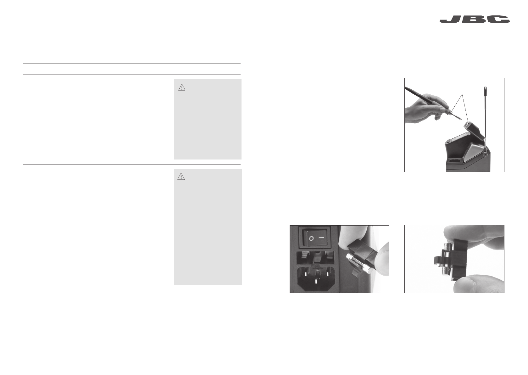
- Replace a blown fuse as follows:
1. Pull off the fuse holder and remove the
fuse. If necessary use a tool to lever it off.
2. Press the new fuse into the fuse holder
and replace it in the station.
Clean
periodically
- Replace any defective or damaged pieces. Use original JBC spare parts only.
- Repairs should only be performed by a JBC authorized technical service.
14 15
Page 9

www.jbctools.com
Safety
It is imperative to follow safety guidelines to prevent electric
shock, injury, fire or explosion.
- Do not use the units for any purpose other than soldering or rework. Incorrect use may cause fire.
- The power cord must be plugged into approved bases. Be sure that it is properly grounded
before use. When unplugging it, hold the plug, not the wire.
- Do not work on electrically live parts.
- The tool should be placed in the stand when not in use in order to activate the sleep mode.
The soldering tip, the metal part of the tool and the stand may still be hot even when the station is
turned off. Handle with care, including when adjusting the stand position.
- Do not leave the appliance unattended when it is on.
- Do not cover the ventilation grills. Heat can cause inflamable products to ignite.
- Use a “non residue” classified flux and avoid contact with skin or eyes to prevent irritation.
- Be careful with the fumes produced when soldering.
- Keep your workplace clean and tidy. Wear appropriate protection glasses and gloves when
working to avoid personal harm.
Specifications
CD-1BE 120V 50/60Hz. Input fuse: 2A. Output: 23,5V. Control Unit model: CD-1E
CD-2BE 230V 50/60Hz. Input fuse: 1A. Output: 23,5V. Control Unit model: CD-2E
CD-9BE 100V 50/60Hz. Input fuse: 2A. Output: 23,5V. Control Unit model: CD-9E
- Weight: 2.6 Kg (5.7 lb)
- Dimensions: 150 x 175 x 145 mm
- Output Peak Power CD-BE: 130W
- Temperature Range: 90-450°C (190°-840°F) (±5%)
- Idle Temp. Stability (still air): ±1.5 ºC / ±3 ºF
- Tip to ground resistance: <2 ohms
- Tip to ground voltage: <2mV RMS
- Ambient operating temp: 10-40 ºC / 50-104 ºF
- USB connector station-PC
Complies with CE standards
ESD protected housing “skin effect”
- Utmost care must be taken with liquid tin waste which can cause burns.
- This appliance can be used by children over the age of eight and also persons with reduced
physical, sensory or mental capabilities or lack of experience provided that they have been given
adequate supervision or instruction concerning use of the appliance and understand the hazards
involved. Children must not play with the appliance.
- Maintenance must not be carried out by children unless supervised.
16 17
Page 10

www.jbctools.com
Estación soldadora
Compact
Ref. CD-BE
18 19
Page 11
www.jbctools.com
Composición
Los siguientes artículos deben estar incluidos:
CD Control Unit
Unidad de Control CD ........................ 1 unidad
Ref. CD-1E (120V)
CD-2E (230V)
CD-9E (100V)
Power Cord
Cable de Red ......................................... 1 unidad
Ref. 0009417 (100V/120V)
0009401 (230V)
General Purpose Handle
Mango para aplicaciones generales ....... 1 ud
Ref. T245-A
Cartridges
Cartuchos .......................................... 2 unidades
Ref. C245903 (x1)
C245741 (x1)
Características
Cambio rápido
de cartucho
Pantalla de
control
Soporte Ajustable:
Gestión inteligente
del calor
Recogecable
Limpiador
de puntas
General Purpose Handle
Mango para aplicaciones generales
Ref. T245-A
Brass Wool
Lana de latón ........ 1 unidad
Ref. CL6210
Sponge
Esponja ................... 1 unidad
Ref. S0354
Manual .................... 1 unidad
Ref. 0017353
www.j bct ools .co m
Interruptor de red
Fusible
Entrada de Red
Compact Soldering Station
Ref. CD-BE
Conector USB-B
Conexión Equipotencial
20 21
Page 12
www.jbctools.com
Soporte Ajustable Recogecable
Ajuste el soporte de la herramienta para adaptarlo a su
posición de trabajo.
Coloque el cable en el recogedor para mantener ordenada su
área de trabajo.
(Ref. CC3702)
Limpiador de puntas
Elija la opción que se ajuste mejor a sus necesidades y mejore la transferencia térmica de la punta.
Splashguard Protector anti-salpicaduras
Ref. 0017576
Protege la estación de las salpicaduras
cuando se utiliza
la lana de latón.
Brass Wool
Lana de latón
Ref. CL6210
Método muy eficaz.
Deja una pequeña
capa de estaño
en la punta para
prevenir la oxidación
entre la limpieza y la
rehumectación.
Antisplash Membrane
Membrana protectora
Ref. 0017574
Protege el área de trabajo de salpicaduras en
el momento de limpiar la punta.
Antes de utilizar la lana
se recomienda eliminar el
exceso de estaño acumulado
en la punta con el limpiador.
Wiper Limpiador
Ref. CL0160
Receptáculo resistente a la temperatura
que permite que se pueda eliminar el
exceso de soldadura golpeando
suavemente o limpiando.
Si necesita extraer el protector anti-salpicaduras, siga los siguientes pasos:
1. Gire el pomo. 2. Retire el protector anti-salpicaduras.
Pomo
Otras opciones de limpieza (no incluidas):
Inox Wool
Lana inoxidable
Ref. CL6205
Proporciona una
limpieza superior de la
punta.
Metal Brush
Cepillo de metal
Ref. CL6220
Si se usa con cuidado,
proporciona una limpieza
más profunda.
Wiper Limpiador
Sponge Esponja
Ref. S0354
El método de limpieza menos
dañino. Mantenga la esponja
húmeda con agua destilada
cuando trabaje para evitar el
desgaste de la punta.
Golpeteo:
Sacuda ligeramente los
cartuchos para soltar el
exceso de estaño.
Limpieza:
Utilice las ranuras para
eliminar las partículas
adheridas a la punta.
22 23
Page 13

www.jbctools.com
Mangos compatibles
Para uso general
Funciona con la gama de cartuchos C245
General Purpose Handle
Mango para aplicaciones generales
Ref. T245-A
Blue Handle · Mango azul
Ref. T245-PA
Non-slip Handle · Mango antideslizante
Ref. T245-B
Soft Thermal Insulator Handle · Mango suave con aislamiento térmico
Ref. T245-C
Espuma suave (Ref. 0016057)
Color azul para diferenciarlo rápidamente
de otros soldadores
Antideslizante y de tacto suave
Espuma suave (Ref. 0016057)
Para uso de precisión
Funciona con la gama de cartuchos C210
Precision Purpose Handle · Mango para aplicaciones de precisión
Ref. T210-A
Blue Precision Handle · Mango azul de precisión
Ref. T210-PA
Color azul para diferenciarlo rápidamente
de otros soldadores
Para mayores exigencias
Importante: En una estación CD sólo funcionan si se utilizan con cartuchos C245.
Indicados en trabajos de soldadura intensivos que requieran una alta potencia térmica
continuada. Presentan un diámetro más grande e incorporan un tornillo para fijar el cartucho.
HD Purpose Handle HD Purpose Handle + 3m cable
Mango HD Mango HD con cable de 3m
Ref. T470-A Ref. T470-SA
Tri-lobed HD Handle · Mango HD trilobular
Cambie fácilmente la empuñadura de los mangos T245-A y T245-C usando los aplicadores
(Ref. 0016057 Se incluyen 4 unidades).
1. Inserte los aplicadores 2. Inserte el mango 3. Quite los aplicadores
aplicador
nueva
empuñadura
Introduzca los aplicadores en
la nueva empuñadura.
Inserte el conjunto en el mango
y empuje hasta que quede bien
situado.
Nota: Todos los modelos se suministran con un cable de 1,5 m.
Para extraer los aplicadores
agarre la empuñadura y tire
hacia arriba (con unos alicates si
es necesario).
Ref. T470-ZA
Para un mejor control manual de la herramienta.
Thermal Insulator HD Handle Thermal Insulator HD Handle + 3m cable
Mango HD con aislamiento térmico Mango HD con aislamiento térmico con cable de 3m
Ref. T470-FA Ref. T470-MA
Nota: Todos los modelos se suministran con un cable de 1,5 m excepto aquellos indicados con 3 m.
Espuma
24 25
Page 14

ø 1
ø 1,5
ø 3,5
www.jbctools.com
Cambio rápido de cartuchos
Ahorre tiempo y cambie cartuchos con seguridad sin desconectar la estación.
1. Retirar 2. Insertar 3. Fijar
C
B
Coloque el lápiz soldador
en las ranuras del extractor y tire hacia arriba para
retirar el cartucho.
*
Importante
Es imprescindible insertar los cartuchos hasta la marca para una conexión correcta.
Coloque el lápiz soldador
en la parte superior del
nuevo cartucho y empuje
hacia abajo ligeramente.
Utilice los agujeros fijadores
para ajustar el cartucho*:
A. Para los rectos C210.
B. Para los curvados C210.
C. Para cartuchos C245.
Conector USB
Descargue los últimos softwares y actualizaciones en nuestra web para mejorar su estación.
JBC Updater · Actualizador JBC
www.jbctools.com/software.html
Actualice el programa (software) a través de la conexión USB:
A
Cable USB AB
JBC Manager · Gestor JBC
www.jbctools.com/manager.html
Gestione y monitorice tantas estaciones como su ordenador permita utilizando el JBC Manager
(Gestor JBC). Puede exportar los datos a otros PCs.
JBC
Updater
Marca
Cartuchos compatibles
Las estaciones CD funcionan con cartuchos C245 y mangos T245/T470 o con cartuchos C210 y
mangos T210. Encuentre el modelo que mejor se adapte a sus necesidades en www.jbctools.com
Cable
USB AB
USB
Hub
Manager Settings
Configuración del gestor
Edite parámetros o gestione
un grupo de estaciones JBC
Redondo Cincel Redondo
curvado
A
B
Bisel Modelos especiales
JBC
Manager
al mismo tiempo.
Register Settings
Configuración de registro
Obtenga gráficos del proceso
de soldadura con datos de
temperatura y potencia en
tiempo real.
26 27
cualquier
estación JBC
Page 15

www.jbctools.com
Funcionamiento
El Exclusivo Sistema Calefactor de JBC
Esta tecnología revolucionaria es capaz de recuperar la temperatura extremadamente rápido.
Esto permite al usurio trabajar con temperaturas más bajas.
Y como resultado, la vida de la punta puede incrementarse hasta 5 veces.
1. Trabajo
Cuando se levanta la
herramienta del soporte, la
punta se calentará hasta la
temperatura seleccionada.
2. Sleep
Cuando la herramienta está
en el soporte, la temperatura
se reduce a la temperatura de
Sleep predefinida.
3. Hibernación
Largos
períodos en
el soporte
Tras largos períodos de
inactividad, se corta el
suministro de energía y
la punta se enfría hasta
temperatura ambiente.
Control del proceso
Pantalla de trabajo
Proporciona información
útil del estado de la
herramienta en tiempo real.
Pantalla de menú
PIN original: 0105
Fixed temp.
Levels ºC
Selected temp.
35 0 oC
27 0 3 50 40 0
35 0 oC
350
P o we r 5 %
Mai n me nu
Exit
1 Reset settings
Station settings
2
3
Tool settings
Se muestra cuando se fija una
temperatura específica.
Se muestra cuando se activan
los niveles de temperatura.
Los valores se deben ajustar
0
c
- 1 0
según necesidad.
Se muestra cuando se utiliza
“Temp. Adjust”, un ajuste más
preciso entre la temperatura
seleccionada y la real.
4 Counters
Program version
Selected temp
350
P o we r 5 %
· Cambie la temperatura
(de 90 a 450ºC)
· Seleccione niveles de
temperatura
· Fije una temperatura
35 0 oC
0
c
Sleep
0
c
350 350
S l ee p t em p 1 50oC
· Cambie la temp. de Sleep
· Retrase el tiempo de
entrada al modo Sleep
(de 0 a 9 min o no Sleep)
Hibernation
0
c
To ol in the sta nd, no hea t
· Retrase el tiempo de
entrada al modo Hibernación
(de 0 a 35 min)
- 1 0
Sta ti on s et ti ng s
1 Temp unit
2
Maximum temp 4000C
3
Minimum temp 2000C
4
Metronome ----
5 Help text OFF
6 Beep ON
7
Change PIN
Celsius
Bac k
5
Too l se tt in gs
1
Fix one temp -----
2
Temp levels set OFF
3
Sleep delay 0 min
Tool
4
Sleep temp 1500C
5
Hibernation delay 10 min
6
Temp adjust + O OC
Tool 245
245
Cou nt er s
1
Plugged hours 0
2
Working hours 0
3
Sleep hours 0
4
Hibernation hours 0
5
No tool hours 0
6 Sleep cycles
0
Bac kBac k
28 29
Page 16

Parámetros
Tenga en cuenta que un uso indebido de los parámetros puede reducir la vida de la punta. Por
favor, siga las siguientes indicaciones:
www.jbctools.com
Configuración de la estación (Station Settings)
Descripción del parámetro
Unidad de temperatura
Celsius (ºC) o Fahrenheit (ºF)
Temperatura máxima
Seleccione la temperatura
máxima de trabajo.
Configurado por defecto
a 400°C (750°F) ya que se
considera un valor suficiente
para trabajar con la mayoría
de aplicaciones sin plomo.
Temperatura mínima
Seleccione la temperatura
mínima de trabajo.
Configurado por defecto a
200ºC ya que se considera
un valor adecuado para empezar a soldar con la mayoría
de aplicaciones con plomo.
Metrónomo
Permite activar un sonido
beep para repetirlo entre
1 y 50 segundos.
Texto de ayuda
Actívelo para recibir información de la estación.
Recomendaciones
N/a
El rango de temperatura de
la estación es 90-450ºC
(190-840ºF). Modifique los
límites de temperatura cuando trabaje con aplicaciones
menos comunes como son
las soldaduras con bajos /
altos puntos de fusión o los
plásticos (p. ej. riveting).
Ideal para trabajos repetitivos
ya que marca el ritmo de
trabajo a seguir. El sonido establece el tiempo de contacto
de la punta con la soldadura.
N/a
Advertencias
En general, trabajar
con temperaturas por
encima de 400°C (750°F)
puede dañar el PCB y los
componentes. Incluso en
tiempos cortos de contacto de la punta con la
soldadura, el flux podría no
funcionar correctamente y
reducir la vida de la punta.
En este caso la soldadura
requiere más potencia (p.
ej. PCBs multicapa o de
gran disipación). JBC recomienda utilizar la ayuda
del precalentador.
N/a
N/a
Configuración de la Herramienta (Tool Settings)
Recomendaciones Descripción del parámetro Advertencias
Fijar una temperatura
Fije un valor dentro del rango
de temperatura de la estación
90-450ºC (190-840ºF).
Niveles de temperatura
Similar al parámetro “Fijar una
temperatura”. En este caso se
pueden configurar 3 valores
de temperatura.
Retraso de Sleep
Configure el tiempo que la
herramienta permanecerá a la
temperatura seleccionada en
el soporte antes de entrar en
el modo Sleep.
Tras agotarse el tiempo, la
temperatura de la punta caerá hasta el valor de Sleep.
Ideal para trabajos en los que
se deben soldar más de un
componente a una temperatura específica. La estación
queda protegida por PIN y
deniega cualquier intento de
cambio de temperatura.
Permite conmutar entre diferentes unidades de temperatura definidas por el usuario.
Puede configurar hasta 3
temperaturas en función de
cada aplicación.
Dado que nuestras herramientas pueden alcanzar la
temperatura de trabajo desde
la temperatura de Sleep en
pocos segundos, este parámetro viene preconfigurado a
0 min. Una vez la herramienta
se coloque en el soporte, la
temperatura de la punta cae
automáticamente al valor de
Sleep, hecho que alarga su
vida útil y reduce la oxidación.
Restañar la punta antes de
colocar la herramienta en el
soporte también ayudará a
proteger su recubrimiento y
garantizar su larga duración.
N/a
N/a
Configurar este
parámetro con valores
más altos acelerará
innecesariamente la
oxidación y acortará la
vida de la punta,
especialmente cuando se
trabaje con temperaturas
de hasta 450°C (840°F).
Beep
Active el sonido del teclado.
Cambie el PIN
Permite modificar el código
PIN de seguridad (0105).
N/a
La estación requiere entrar el
PIN cada vez que el usuario
entra en el menú para modificar cualquier parámetro.
N/a
N/a
Temperatura de Sleep
Es la temperatura que la
herramienta tendrá cuando
descanse en el soporte.
Las temperaturas de Sleep
están preconfiguradas para
conseguir un compromiso entre la prevención de oxidación
y la disposición para alcanzar
la temperatura de trabajo en
pocos segundos.
30 31
Page 17
Configuración de la Herramienta (Tool Settings)
www.jbctools.com
Mantenimiento
Antes de almacenar o de su mantenimiento, desconecte el equipo y déjelo enfriar.
Retraso de Hibernación
Configure el tiempo que la
herramienta permanecerá
en temperatura de Sleep
antes de entrar al modo de
Hibernación. Configurado por
defecto a 10 min.
Tras agotarse el tiempo, la
estación cortará el suministro de energía y la punta se
enfriará hasta temperatura
ambiente.
Ajuste de temperatura
Permite un ajuste más
preciso entre la temperatura
seleccionada en la estación
y la temperatura real en la
punta.
Recomendaciones Descripción del parámetro Advertencias
Esta función protege completamente la punta de la
oxidación durante largos
periodos de inactividad. Es
decir mientras la herramienta
permanezca en el soporte.
Restañar la punta antes de
colocar la herramienta en el
soporte también ayudará a
proteger su recubrimiento y
garantizar su larga duración.
El usuario puede ajustar valores dentro del intervalo ±50°C
(±90°F) hasta conseguir error
cero. JBC recomienda usar
los termómetros TID-A o
TIA-A para obtener lecturas
más fiables.
Configurar este
parámetro con valores
más altos que el valor de
fábrica acelerará
innecesariamente la
oxidación y acortará la
vida de la punta.
Cuando se cambie de
modelo de cartucho, se
debe resetear este parámetro a 0°C/F o ajustarlo
al cartucho a utilizar.
P. ej. Si se establece una
corrección de +20°C
(+36°F) para el modelo
C245966 (grueso) y el
usuario cambia el cartucho por un C245030 (más
fino) sin resetear, el usuario
estaría trabajando a 20°C
(+36°F) de temperatura
más baja cuando el modelo C245030 no necesita
ningún ajuste de temperatura.
- Use un paño húmedo para limpiar la pantalla
del equipo, la carcasa y la herramienta.
Solamente utilice alcohol para las
partes metálicas.
- Compruebe periódicamente que las partes
metálicas de la herramienta y el soporte
están limpias así la estación puede
detectar el estado de la herramienta y
activar los modos Sleep o Hibernation.
- Mantenga limpia y estañada la superfície
de la punta para evitar la oxidación. Las
superfícies sucias reducen la transferencia
térmica a la soldadura.
- Revise la conexión de cables y/o tubos.
- Cambie el fusible fundido de acuerdo a las siguientes instrucciones:
1. Retire el fusible tirando de la tapa negra.
Si fuera necesario, utilice una palanca.
2. Coloque el nuevo fusible en su sitio
presionando ligeramente.
Limpie
periódicamente
- Cambie cualquier pieza defectuosa o dañada. Utilice solamente recambios originales de JBC.
- Cualquier reparación sólo podrá ser realizado por un servicio técnico oficial JBC.
32 33
Page 18

www.jbctools.com
Seguridad
Es necesario cumplir estas normas de seguridad para prevenir cualquier
choque eléctrico, heridas, fuego o explosiones.
- No utilice el equipo para otros fines que no sea la soldadura o reparación. El uso incorrecto
puede causar fuego.
- El cable de red debe enchufarse en bases homologadas. Asegúrese de que está conectado a
tierra correctamente antes de su uso. Al desenchufarlo, tire del conector, no del cable.
- No trabaje con tensión.
- La herramienta debe permanecer en el soporte cuando no está en uso con el fin de activar el modo
de Sleep. El cartucho, la parte metálica de la herramienta y el soporte puede estar caliente incluso
cuando la estación está apagada. Manipule con cuidado, incluso cuando ajuste la posición del
soporte.
- No deje el aparato desatendido cuando esté en funcionamiento.
- No cubra las rejillas de ventilación. El calor puede causar que los productos inflamables se enciendan.
- Utilice un flux clasificado como “non residue” y evite el contacto con la piel y los ojos para evitar
que se irriten.
- Tenga cuidado con el humo producido al trabajar.
Especificaciones
CD-1BE 120V 50/60Hz. Fusible de entrada: 2A. Salida: 23,5V. Unidad de Control: CD-1E
CD-2BE 230V 50/60Hz. Fusible de entrada: 1A. Salida: 23,5V. Unidad de Control: CD-2E
CD-9BE 100V 50/60Hz. Fusible de entrada: 2A. Salida: 23,5V. Unidad de Control: CD-9E
- Peso: 2.6 Kg (5.7 lb)
- Dimensiones: 150 x 175 x 145 mm
- Potencia máxima CD-BE: 130W
- Rango de temperatura: 90-450 °C (190-840 °F) (±5%)
- Estabilidad de temperatura en reposo: ±1.5 ºC (±3 ºF)
- Resistencia punta a tierra: <2 ohms
- Tensión en punta: <2mV RMS
- Temperatura ambiente de trabajo: 10-40 ºC / 50-104 ºF
- Conector USB estación-PC
Cumple con las normativas CE.
Seguridad ESD
- Mantenga su lugar de trabajo limpio y ordenado. Use gafas y guantes de protección adecuados.
Así evitará cualquier daño.
- Tenga cuidado con los restos de estaño líquido. En contacto con la piel, puede causar quemaduras.
- Este aparato puede ser utilizado por personas a partir de 8 años y también por aquellas
personas con movilidad reducida o capacidades físicas, sensoriales o mentales limitadas o
con falta de experiencia y conocimientos siempre y cuando reciban supervisión o instrucciones
relativas al uso del aparato de una manera segura y entiendan los riesgos que implica. Los niños
no deben jugar con el aparato.
- Los niños no deberán realizar tareas de mantenimiento sin supervisión.
34 35
Page 19

www.jbctools.com
Lötstation Kompakt
Ref. CD-BE
36 37
Page 20
www.jbctools.com
Packliste
Die folgenden Artikel sollten enthalten sein:
CD Control Unit
CD Steuereinheit ................................. 1 Einheit
Ref. CD-1E (120V)
CD-2E (230V)
CD-9E (100V)
Power Cord
Netzkabel................................................ 1 Einheit
Ref. 0009417 (100V/120V)
0009401 (230V)
General Purpose Handle
Universal-Handstück ........................... 1 Einheit
Ref. T245-A
Cartridges
Kartuschen ....................................... 2 Einheiten
Ref. C245903 (x1)
C245741 (x1)
Merkmale
SpitzenSchnellwechsler
ProzessSteuerung
Verstellbare Ablage:
Intelligentes
Heizmanagement
Kabelausleger
Spitzenreinigungssystem
General Purpose Handle
Universal-Handstück
Ref. T245-A
Brass Wool
Messingwolle ......... 1 Einheit
Ref. CL6210
Sponge
Schwamm .............. 1 Einheit
Ref. S0354
Handbuch .............. 1 Einheit
Ref. 0017353
www.j bct ools .co m
Hauptschalter
Sicherung
Netzsteckdose
Compact Soldering Station
Ref. CD-BE
USB-B-Anschluss
Potenzialausgleichsbuchse
38 39
Page 21

www.jbctools.com
Verstellbare Ablage Kabelausleger
Stellen Sie die Werkzeugablage
passend auf Ihre Arbeitsposition ein.
Fixieren Sie das Kabel am Aufleger und stellen ihn so ein, um
Kabelsalat zu vermeiden.
Spitzenreinigungssystem
Wählen Sie die Option aus, die am besten Ihre Reinigungsbedürfnisse erfüllt.
Splashguard
Spritzschutz
Ref. 0017576
Verhindert Lötmittelspritzer beim Einsatz von
Messinggeflecht.
Brass Wool
Messingwolle
Ref. CL6210
Sehr wirksame
Reinigungsmethode.
Lässt eine dünne
Lotschicht auf der
Spitze, wodurch die
Oxidation
zwischen Reinigung
und Rückbenetzung
vermieden wird.
Wiper Ref. CL0160
Spitzenabstreifer
Ein temperaturbeständiger Behälter ermöglicht es dem Werker,
durch vorsichtiges Abklopfen oder Abstreifen überschüssiges Lot zu
entfernen.
(Ref. CC3702)
Antisplash Membrane
Schutzmembran
Ref. 0017574
Vermeidet Spritzer, um den Arbeitsbereich
sauber zu halten.
Falls die Spitze stark
verschmutzt sein sollte,
wird empfohlen, mit
dem Spitzenabstreifer
das überflüssige Zinn zu
entfernen.
Wenn Sie den Spritzschutz entfernen müssen, befolgen Sie folgende Schritte:
1. Entriegeln Sie den Spritzschutz.
Weitere Optionen für den Spritzschutz (nicht im Lieferumfang enthalten):
Inox Wool
Edelstahlwolle
Ref. CL6205
Sorgt für eine bessere
Reinigung an der Spitze.
Spitzenabstreifer
Abklopfen:
Sponge Schwamm
Ref. S0354
Die schonendste Reinigungsmethode. Halten Sie den
Schwamm bei der Arbeit mit
destilliertem Wasser feucht, um
Spitzenverschleiß zu vermeiden.
Klopfen Sie vorsichtig ab,
um überschüssiges Lot zu
entfernen.
2. Nehmen Sie ihn heraus.
Metal Brush
Metallbürste
Ref. CL6220
Bei sorgfältiger
Benutzung sorgt sie
für eine gründlichere
Reinigung.
Abstreifen:
Benutzen Sie die
Aussparungen, um noch
vorhandene Partikel
abzustreifen.
40 41
Page 22

www.jbctools.com
Kompatible Handstücke
Für allgemeine Anwendungen
C245 Kartuschensortiment
General Purpose Handle
Universal-Handstück
Ref. T245-A
Blue Handle · Universal-Handstück, blauer Griff
Ref. T245-PA
Non-slip Handle · Universal-Handstück, rutschfester Griff
Ref. T245-B
Soft Thermal Insulator Handle · Schaumstoffgriff mit Wärmeisolierung
Ref. T245-C
Softtouch-Griff und Wärmeisoliertes (Ref. 0016057)
Dies ermöglicht Ihnen, das bei Lötarbeiten mit
Bleilegierungen benutzte Handstück von dem bei
bleifreien Aufträgen benutzten zu unterscheiden.
Rutschfester und Softtouch-Griff
Softtouch-Griff und Wärmeisoliertes (Ref. 0016057)
Für Präzisionsanwendungen
C210 Kartuschensortiment
Precision Purpose Handle · Präzisions-Handstück
Ref. T210-A
Blue Precision Handle · Präzisions-Handstück, blauer Griff
Ref. T210-PA
Dies ermöglicht Ihnen, das bei Lötarbeiten mit
Bleilegierungen benutzte Handstück von dem bei
bleifreien Aufträgen benutzten zu unterscheiden.
Für größere Nachfrage
Wichtig
Handstücke für intensive Lötaufgaben, die ständig hohe Temperaturanforderungen stellen. Sie
bieten eine größere Griffstärke und eine Schraube, die die Kartusche fixiert.
HD Purpose Handle HD Purpose Handle + 3m cable
HD Handstück HD Handstück mit Kabel 3m
Ref. T470-A Ref. T470-SA
: Arbeiten Sie nur mit C245-Kartuschen, wenn sie an einer CD-Station benutzt werden.
Tri-lobed HD Handle · Dreilappiges Handstück
Ersetzen Sie problemlos die T245-A-Griffe und T245-C-Griffe mit den Gleitstreifen (Ref. 0016057 Mit
4 Griffen ausgeliefert)
1. Streifen einschieben
Streifen
neuer Griff
Stecken Sie die Gleitstreifen
in den neuen Griff.
2. Handstück einführen 3. Streifen herausziehen
Schieben Sie den Griff mit den
Streifen auf das Handstück.
Hinweis: Alle Modelle werden mit einem 1,5 m langen Kabel ausgeliefert
Um die Streifen zu entfernen,
halten Sie den Griff fest und
ziehen sie heraus.
Ref. T470-ZA
Für eine größere manuelle Werkzeugkontrolle.
Thermal Insulator HD Handle Thermal Insulator HD Handle + 3m cable
Wärmeisoliertes HD Handstück Wärmeisoliertes Handstück mit Kabel 3m
Ref. T470-FA Ref. T470-MA
Alle Modelle werden mit einem 1,5 m langen Kabel ausgeliefert außer diejenigen, bei denen 3 m spezifiziert ist.
Geschäumte
Hinweis:
42 43
Page 23

ø 1
ø 1,5
ø 3,5
www.jbctools.com
Spitzen-Schnellwechsler
Sparen Sie Zeit und wechseln Sie sicher Kartuschen, ohne die Station auszuschalten.
1. Entfernen 2. Einsetzen 3. Fixieren
C
B
Handstück im Abzieher
positionieren und Kartusche
entfernen.
Handstück auf der neuen
Kartusche positionieren,
leichten Druck nach unten
ausüben und Handstück
aus dem Abzieher nehmen.
Drücken Sie die Kartusche*
wie folgt in die Fixieröffnungen:
A. Für gerade C210.
B. Für abgeschrägte C210.
C. Für C245.
*Wichtig
Es ist wichtig, die Kartuschen für eine korrekte Verbindung genau bis zur Markierung einzustecken.
A
USB-Anschluss
Laden Sie die neueste Software von unserer Website herunter, um Ihre Lötstation zu verbessern.
JBC Updater
www.jbctools.com/software.html
Aktualisieren Sie die Stations-Software über USB-Verbindung:
Kabel USB AB
JBC Manager
www.jbctools.com/manager.html
Verwalten und überwachen Sie mit dem JBC Manager an einen PC angeschlossene Stationen:
JBC
Updater
Ausrichtung
Kompatible Kartuschen
Die CD-Stationen können sowohl die C245- als auch die C210-Kartuschen nur mit dem passenden
Handstück benutzen: T245/T470 oder T210. Finden Sie das passende Modell für Ihren Lötbedarf
unter www.jbctools.com
Cable
USB AB
USB
Hub
Manager Settings
Ändern Sie Einstellungen für
eine Gruppe von
JBC-Stationen gleichzeitig.
Register Settings
Erstellen Sie Grafiken des
Lötprozesses in Echtzeit mit
Leistungs- und Temperaturdaten.
Rund Meißel Rundgebogen Abgeschrägt
A
B
Spezialmodelle
JBC
Manager
44 45
jede JBC
Station
Page 24

www.jbctools.com
Betrieb
Das exklusive Heizsystem von JBC
Diese revolutionäre Technik ist dazu in der Lage, außerordentlich schnell die Spitzentemperatur zu
erreichen. Dies ermöglicht es dem Benutzer, mit einer niedrigeren Temperatur zu arbeiten.
Daraus ergibt sich eine fünfmal längere Spitzenstandzeit.
1. Arbeit
Nehmen Sie das Werkzeug
aus der Ablage und die
Werkzeugspitze wird auf
die gewählte Temperatur
aufgeheizt.
2. Sleep
Wenn sich das Werkzeug in
der Ablage befindet, wird die
Temperatur auf voreingestellte
Sleep-Temperatur abgesenkt.
3. Überwinterung
Lange Zeit in
die Ablage
Nach längeren Zeiträumen
der Untätigkeit wird die
Stromversorgung abgeschaltet
und das Werkzeug
kühlt auf Raumtemperatur ab.
Prozess-Steuerung
Arbeitsbildschirm
Der Arbeitsbildschirm
liefert in Echtzeit wertvolle
Informationen über den
Spitzenstatus.
Menübildschirm
Original-PIN: 0105
Fixed temp.
Levels ºC
Selected temp.
35 0 oC
27 0 3 50 40 0
35 0 oC
350
P o we r 5 %
Mai n me nu
Exit
1 Reset settings
Station settings
2
3
Tool settings
Zeigt eine spezifische
Fixtemperatur an.
Angezeigt, wenn Sie
Temperaturstufen ausgewählt
haben.
0
c
- 1 0
“Temp. Anpass” Parameter.
Sorgt für eine präzisere
Anpassung zwischen der
ausgewählten Temperatur
und der derzeitigen.
4 Counters
Program version
Selected temp
350
P o we r 5 %
· Temperatur ändern
(de 90 a 450ºC)
· Temperaturstufen wählen
· Temperatur eingestellt
35 0 oC
0
c
Sleep
0
c
350 350
S l ee p t em p 1 50oC
· Sleep-Temperatur ändern
· Sleepverzögerung einstellen
(von 0 bis 9 Min oder kein Sleep)
Hibernation
0
c
To ol in the sta nd, no hea t
· Überwinterungsverzögerung
ändern (von 0 bis 35 Min)
Sta ti on s et ti ng s
1 Temp unit
2
Maximum temp 4000C
3
Minimum temp 2000C
4
Metronome ----
5 Help text OFF
6 Beep ON
7
Change PIN
Celsius
Bac k
5
Too l se tt in gs
1
Fix one temp -----
2
Temp levels set OFF
3
Sleep delay 0 min
Tool
4
Sleep temp 1500C
5
Hibernation delay 10 min
6
Temp adjust + O OC
Tool 245
245
Cou nt er s
1
Plugged hours 0
2
Working hours 0
3
Sleep hours 0
4
Hibernation hours 0
5
No tool hours 0
6 Sleep cycles
0
Bac kBac k
46 47
Page 25

Parameter
Seien Sie bei der Benutzung dieser Parameter vorsichtig, da sie bei unsachgemäßer Anwendung
die Standzeit der Spitze verkürzen können. Bitte beachten Sie die empfohlenen Richtlinien:
www.jbctools.com
Stationseinstellungen
Parameterbeschreibung
Temperatureinheit
Celsius (ºC) oder Fahrenheit (ºF)
Maximaltemperatur
Legen Sie die Maximaltemperatur
fest, mit der gearbeitet werden
soll.
Standard-Max.temp beträgt 400
°C (750 °F). Dies wird als ausreichend für die Arbeit mit den
meisten bleifreien Anwendungen
angesehen.
Minimaltemperatur
Stellen Sie die
Minimaltemperatur ein mit der
gearbeitet werden soll.
Standard Min.temp. beträgt
200 ºC (392 ºF). Diese wird als
ein geeigneter Ausgangspunkt
für mit Blei arbeitende Anwendungen angesehen.
Metronom
Dies aktiviert einen Piepton,
der im Abstand von 1 bis 50
Sekunden wiederholt wird.
Hilfetext
Aktivieren Sie diesen Parameter,
um vom System Info zu erhalten.
Piepton
Aktivieren/deaktivieren des
Pieptons des Tastenfelds.
PIN ändern
Die Standard-Sicherheits-PINNummer (0105) ändern.
Empfehlungen
unzutreffend
Der Temperaturbereich
der Station liegt zwischen
90 - 450 ºC
(190-840 ºF). Ändern Sie die
Temperaturgrenzwerte, wenn
Sie mit ungebräuchlicheren
Anwendungen wie etwa unterem
/ oberen Schmelzpunkt (HMP)
Löten oder Kunststoffen (z.B.
riveting) arbeiten.
Nützlich für die Vorgabe einer
Arbeitsgeschwindigkeit bei sich
wiederholenden Arbeiten. Der
Piepton lässt Sie den Zeitraum
abschätzen, den die Spitze die
Lötstelle berühren muss.
unzutreffend
unzutreffend
Die PIN muss immer eingegeben werden, wenn ein
Parameter geändert wird.
Warnungen
In den meisten Fällen
kann die Arbeit bei Temperaturen von über 400 ºC
(750 ºF) die PCB und ihre
Komponenten schädigen.
Je kürzer die Zeiträume des
Kontakts der Spitze mit der
Lötstelle sind, umso weniger
kann das Flussmittel korrekt
arbeiten und ernsthaft die
Spitzenstandzeit verkürzen.
Wenn die Lötstelle höhere
Leistungsansprüche stellt
(z.B. Mehrschicht-Leiterplatten oder Platten mit hoher
Wärmeabfuhr), empfiehlt
JBC nachdrücklich andere
Hilfsmittel wie Vorheizgeräte
zu verwenden.
unzutreffend
unzutreffend
unzutreffend
unzutreffend
Werkzeug-Einstellungen
Parameterbeschreibung
Eine Temperatur festlegen
Einen Wert innerhalb des
Temperaturbereichs der
Station festlegen (90-450
ºC/190-840 ºF).
Temperaturstufen eingestellt
Ähnlich wie Parameter "Fix
one temp". In diesem Fall
kann der Nutzer bis zu 3
Werte für unterschiedlichen
Leistungsbedarf einstellen.
Ruheverzögerung
Stellt die Zeit ein, die das
in der Ablage befindliche
Werkzeug auf der eingestellten Temperatur bleiben wird,
bevor es in Ruhezustand umschaltet. Die Spitzentemperatur
wird dann auf die Ruhetemperatur.
Ruhetemperatur
Ist die eingestellte Temperatur,
die die Spitze beim Abstellen
des Werkzeugs in der Ablage
erreicht.
Empfehlungen
Ideal zum Löten von mehreren Bauteilen mit einer
bestimmten Temperatur. Die
Station wird jeden Versuch
der Temperaturänderung
abweisen.
Dies ermöglicht einen schnellen Wechsel zwischen 3
verschiedenen Temperaturen. Stellen Sie sie nach den
zulässigen Werten für Ihre
Lötanwendungen ein.
Damit unsere Werkzeuge aus
dem Standard-Ruhemodus
in nur wenigen Sekunden die
Arbeitstemperatur erreichen
können, ist dieser Parameter
auf 0 Min. voreingestellt. Sobald das Werkzeug wieder in
die Ablage gestellt wird, wird
die Temperatur automatisch
auf die Ruhetemperatur abgesenkt, wodurch die Standzeit
verlängert und Oxidation
vermieden wird. Neuverzinnen
der Spitze vor dem Abstellen
des Werkzeugs in der Ablage
wird die Abnutzung des Überzugs verhindern.
Die Ruhetemperaturen sind
so eingestellt, um einen Kompromiss zwischen Oxidationsvorbeugung und Bereitschaft
zum Erreichen der Arbeitstemperatur in wenigen Sekunden herzustellen.
Warnungen
unzutreffend
unzutreffend
Das Einstellen dieser
Parameter auf höhere
Werte, wird unnötig die
Oxidation beschleunigen
und die Spitzenstandzeit
verkürzen
vor allem wenn mit Temperaturen oberhalb von
450 ºC (840 ºF) gearbeitet
wird.
48 49
Page 26

Werkzeug-Einstellungen
Parameterbeschreibung
Standbyverzögerung
Stellt die Zeit ein, die das
Werkzeug die Ruhetemperatur hält, bevor es aus Standby
schaltet.
Nach diesem Zeitraum wird
die Stromversorgung abgeschaltet und die Spitze hält die
Umgebungstemperatur.
Temp Anpass
Sorgt für eine präzisere
Anpassung zwischen der
ausgewählten Temperatur
und der derzeitigen.
Empfehlungen
Diese Funktion verhindert
vollständig, dass die Spitze
während langen Zeiträumen
der Untätigkeit, in denen sich
das Werkzeug in der Ablage
befindet, rostet.
Erneutes Verzinnen der
Spitze vor dem Abstellen des
Werkzeugs in der Ablage hilft
ebenso, die Spitzenversiegelung vor Rost zu schützen
und die Spitzenstandzeit zu
verlängern.
Werte innerhalb ±50 °C
(± 90 °F) einstellen, um
Nullfehler zu erreichen. JBC
empfiehlt nachdrücklich die
Benutzung von TID-A oder
TIA-A-Thermometern, um
präzise Ableseergebnisse zu
erhalten.
Warnungen
Anheben des Werts
wird die Oxidation beschleunigen und die Spitzenstandzeit verkürzen.
Wenn der Nutzer
das Kartuschenmodell
wechselt, sollte dieser
Parameter auf 0 ºC/F oder
den von dieser Kartusche
benötigten Wert zurückgesetzt werden. z.B. Wenn
eine Korrektur von +20
°C (+36 °F) für C245966
(dickes Modell) eingestellt
ist und dann der Nutzer
die Kartusche durch eine
C245030 (die dünner ist)
ersetzt ohne zurückzusetzen, würde er mit einer
20 °C (+36 °F) niedrigeren
Temperatur arbeiten, wenn
C245030 keine Temperaturanpassung benötigt.
www.jbctools.com
Wartung
Vor der Durchführung von Wartungsarbeiten oder Einlagerung die Geräte immer erst auskühlen lassen.
- Reinigen Sie den Bildschirm der Station mit
einem Glasreiniger oder einem feuchten
Lappen.
- Benutzen Sie einen feuchten Lappen, um
das Gehäuse und das Werkzeug zu
reinigen. Alkohol darf nur zur Reinigung der
Metallteile benutzt werden.
- Regelmäßig überprüfen, dass die
metallischen Teile des Werkzeugs/der
Ablage sauber sind, damit die Station
erkennen kann, wenn das Werkzeug in der
Ablage steht.
- Halten Sie die Oberfläche der Spitze vor
der Aufbewahrung sauber und verzinnt, um
Spitzenoxidation zu vermeiden. Angerostete
und verschmutzte Oberflächen mindern den
Wärmedurchgang zur Lötstelle.
- Überprüfen Sie regelmäßig alle Kabel und Schlauchanschlüsse.
- Ersetzen Sie die Sicherung, wenn sie durchgebrannt ist, gemäß folgender Anweisungen:
1. Entfernen Sie die Sicherung, indem Sie an
der schwarzen Kappe ziehen. Falls
notwendig, benutzen Sie ein Werkzeug,
um sie herauszudrücken.
2. Drücken Sie die neue Sicherung in die
Halterung und setzen Sie sie erneut in die
Station ein.
Regelmäßig
reinigen
- Jedes defekte oder schadhafte Teil austauschen. Nur Original-Ersatzteile von JBC verwenden.
- Reparaturen dürfen nur von dem Vertragskundendienst von JBC durchgeführt werden.
50 51
Page 27

www.jbctools.com
Sicherheit
Die Sicherheits-Leitlinien müssen unbedingt eingehalten werden, um elektrischen
Schlag, Verletzung, Feuer oder Explosion zu vermeiden.
- Die Anlage für keinen anderen Zweck verwenden als zum Löten oder Entlöten. Unsachgemäße
Verwendung kann Feuer hervorrufen.
- Das Netzkabel muss in zugelassene Steckdosen eingesteckt werden. Vergewissern Sie sich vor
der Benutzung, dass sie korrekt geerdet ist. Beim Herausziehen, am Stecker ziehen, nicht am
Kabel.
- Nicht an aktiven Bauteilen arbeiten.
- Das Werkzeug sollte bei Nichtgebrauch in der Ablage abgestellt werden, um die Betriebsart
Sleep auszulösen. Die Lötspitze, der metallische Teil des Werkzeugs und die Ablage können
noch heiß sein, wenn die Station ausgeschaltet ist. Gehen Sie vorsichtig vor, sogar wenn Sie die
Standposition justieren.
- Das eingeschaltete Gerät niemals unbeaufsichtigt lassen.
- Die Kühlungsgitter nicht abdecken. Hitze kann entzündliche Stoffe entzünden, sogar wenn sie
sich außerhalb der Sichtweite befinden.
- Ein als “ohne Rückstände” eingestuftes Flussmittel verwenden und die Berührung mit Haut oder
Augen vermeiden, um Reizung zu vermeiden.
Technische Daten
CD-1BE 120V 50/60Hz. Eingangssicherung: 2A. Ausgang: 23,5V. Steuereinheit Modell: CD-1E
CD-2BE 230V 50/60Hz. Eingangssicherung: 1A. Ausgang: 23,5V. Steuereinheit Modell: CD-2E
CD-9BE 100V 50/60Hz. Eingangssicherung: 2A. Ausgang: 23,5V. Steuereinheit Modell: CD-9E
- Gesamtgewicht des Geräts: 2.6 Kg (5.7 lb)
- Abmessungen: 150 x 175 x 145 mm
- Spitzenausgangsleistung: CD-BE: 130W
- Temperaturauswahl: 90-450 °C (190-840 °F) (±5%)
- Idle Temp. Stabilität (noch Luft): ±1.5 ºC (±3 ºF)
- Spitze-Erde-Widerstand: <2 ohms
- Spitze-Erde-Spannung: <2mV RMS
- Umgebungstemperatur: 10-40 ºC / 50-104 ºF
- USB-Anschluss Station-PC
Erfüllt EG-Normen
ESD-gerechtes Gehäuse “skin effect”
- Sich vor dem beim Löten entstehenden Rauch in Acht nehmen.
- Ihren Arbeitsplatz sauber und aufgeräumt halten. Bei der Arbeit geeignete Schutzbrille und
Handschuhe tragen, um gesundheitliche Schäden zu vermeiden.
- Im Umgang mit flüssigen Zinnrückständen muss äußerste Sorgfalt walten.
- Dieses Gerät kann von Kindern über acht Jahren und auch Personen mit körperlicher, sinnlicher
oder geistiger Behinderung oder mangelnder Erfahrung benutzt werden, nachdem ihnen
angemessene Überwachung oder Einweisung hinsichtlich der Verwendung des Geräts und der
damit verbundenen Risiken gegeben worden ist. Kinder dürfen mit dem Gerät nicht spielen.
- Wartung darf nicht von Kindern durchgeführt werden, wenn sie hierbei nicht beaufsichtigt
werden.
52 53
Page 28

需包含以下部件:
www.jbctools.com
产品特性产品描述
CD 控制主机 ............................................1件
Ref.CD-1E(120V)
CD-2E(230V)
CD-9E(100V)
电源线.........................................................1件
Ref.0009417(100V/120V)
0009401(230V)
普通用途手柄 ...........................................1件
Ref.T245-A
烙铁头 .........................................................2件
Ref.C245903(x1)
C245741(x1)
集线器
可调式支架:
智能热管理
快捷烙铁头更换器
操作控制
焊嘴清洁系统
普通用途手柄
Ref.T245-A
铜丝球 ...........................1件
Ref.CL6210
海绵 ...............................1件
Ref.S0354
说明书 ...........................1件
Ref.0017353
www.j bct ools .co m
主开关
保险丝
电源插座
Compact Soldering Station
Ref. CD-BE
USB-B接口
电位连接
54 55
Page 29

可调式支架 集线器 (Ref.CC3702)
www.jbctools.com
调节工具支架,满足工作位
置需求。
将电线放置在集线器上,避免工作位置受到电线干扰。
焊嘴清洁系统
选择最适合您的焊接清洁需求的选择。
防溅罩
Ref.0017576
可防止在使用铜丝清洁球
的时候残锡的飞溅。
铜丝球
Ref.CL6210
有效清洁方法。在清洁
后到下次焊接前对焊
嘴加锡保养,以防焊嘴
氧化。
防溅层
Ref.0017574
防止溅锡确保工作环境的整洁。
如果需要拆下保护罩,请按照以下步骤进行:
1. 松开保护罩扣锁。 2. 撤走保护罩。
其他防溅罩选项(不包括):
不锈钢丝球
Ref.CL6205
为焊嘴提供更深层的
清洁
擦板
敲击
金属刷
Ref.CL6220
如果使用得当,
可提供更彻底的清洁。
擦拭
如果烙铁头非常脏,建议
先刮掉多余的锡。
擦板
Ref.CL0160
耐高温凹槽可以让操作者通过轻轻拍打
或擦拭去除多余的焊锡。
海绵
Ref.S0354
最温和的清洁方法。
工作时用蒸馏水润湿海绵避
免焊嘴磨损。
轻轻敲击除去多余的残锡。
使用槽口擦拭任何残留的锡粒。
56 57
Page 30

www.jbctools.com
兼容手柄
普通用途
与 C245烙铁头系列兼容
普通用途手柄
Ref. T245-A
蓝色普通用途手柄
Ref. T245-PA
防滑手柄
Ref. T245-B
柔软握柄隔热型
Ref. T245-C
柔软海绵(Ref.0016057)
蓝色手柄可快速与其他手柄区分开来
防滑柔软触感
柔软海绵(Ref.0016057)
用于精确操作
与 C210 烙铁头系列兼容
精确用途手柄
Ref.T210-A
蓝色精确手柄
Ref.T210-PA
蓝色手柄可快速与其他手柄区分开来
更高要求
重要:仅与 C245焊头兼容于 CD台。
高精度焊接工作需要持续的高导热。它们提供良好的隔热条件,其中还有一个螺丝固定住烙铁头
以防止打滑。
普通用途HD手柄 普通用途HD手柄,带3米电线
Ref.T470-A Ref.T470-SA
三叶型手柄
Ref.T470-ZA
使用滑动标签可轻松更换T245-A/T245-C握套(型号0016057共四个握套)。
1. 插入标签 2. 套上手柄 3. 移去标签
标签
新握套
将滑动标签插入新握套内。 顺着标签将握套套上手柄。 要移去标签,握住手柄并向
外拉。
注意:所有型号都配有1.5米电线。
更好地握持工具。
隔热HD手柄 隔热HD手柄,带3米电线
Ref.T470-FA Ref.T470-MA
海绵
注意:所有型号都配有1.5米电线,配有3米电线的型号除外。
58 59
Page 31

ø 1
ø 1,5
ø 3,5
www.jbctools.com
USB 接口快速烙铁头更换器
节省时间,安全更换烙铁头,主机无需断电。
1. 移除 2. 插入 3. 固定
C
B
将手柄放置在插拔座上,拔
出烙铁头。
*重要
切记尽量将烙铁头插入到标识处,以确保正确的连接。
标识
将手柄置在新烙铁头顶端,
轻轻下压。
使用孔洞来固定烙铁头*,操
作如下:
A. 直线型烙铁头C210.
B. 弯曲型烙铁头 C210.
C. C245.
自我们官网下载最新软件,确保您的焊台处于最佳状态。
JBC 更新程序 (JBC Updater)
www.jbctools.com/software.html
通过USB接口更新软件。
A
USBAB连接线
JBC
Updater
JBC 管理员 (JBC Manager)
www.jbctools.com/manager.html
通过该程序使用电脑管理和跟踪多台焊台。可将数据导出到其他电脑上。
任何JBC
焊台
兼容烙铁头
CD主机使用C245烙铁头及T245/T470手柄或C210烙铁头及T210手柄。找到最适合你的焊接
需求的款式,请登录www.jbctools.com
A
B
圆头 凿形 圆形弯曲 斜角 特殊型号
Cable
USB AB
USB
端口
JBC
Manager
管理员设置
同时更换一组JBC焊台设置
记录设置
创建实时焊接过程图表,
包括功率和温度数据
60 61
Page 32

www.jbctools.com
操作
JBC 专属加热系统
革命性技术,可以令烙铁头温度快速回升。
这意味着用户可以在较低温度下操作,并提高焊接质量。
之后,烙铁头温度在睡眠和休眠模式下降低,可令其寿命延长五倍。
1. 工作
当工具从支架下取下时,
烙铁头温 度会加热 到选 定温
度。
35 0 oC
0
c
当前温度
电源
P o we r 5 %
预设温度
Selected temp
350
2. 睡眠 (Sleep)
当工具放置在支架上时,
温度会下降到
预置睡眠温度。
睡眠
当前温度
Sleep
0
c
350 350
S l ee p t em p 1 50oC
3. 休眠 (Hibernation)
长时间放置
在支架上
长时间没有使用后,电源会切
断,工具会冷却到室温。
睡眠后工具
在支架上
不加热
休眠
当前温度
Hibernation
0
c
To ol in the sta nd, no hea t
- 1 0
流程控制
工作屏
工作屏提供工具
实时有用信息。
菜单屏
原始密码:0105
退出
重置设置
主机设置
工具设置
计数器
程序版本
计数器
插入小时数
工作小时数
睡眠小时数
电源
Mai n me nu
Exit
1 Reset settings
Station settings
2
3
Tool settings
4 Counters
Program version
5
Cou nt er s
1
Plugged hours 0
2
Working hours 0
3
Sleep hours 0
Fixed temp.
Levels ºC
Selected temp.
350
P o we r 5 %
35 0 oC
27 0 3 50 40 0
35 0 oC
0
c
- 1 0
1 Temp unit
2
3
4
5 Help text OFF
6 Beep ON
7
1
2
3
显示特定固定温度
显示已选温度等级
固定温度
温度修正
提供所选温度和实际温度之
间的更精确的修正。
Sta ti on s et ti ng s
Celsius
Maximum temp 4000C
Minimum temp 2000C
Metronome ----
Change PIN
Bac k
Bac k
Too l se tt in gs
Fix one temp -----
Temp levels set OFF
Sleep delay 0 min
Tool 245
主机设置
温度单位
最高温度
最低温度
节拍器
帮助文本
嘀音
更换密码
返回
工具设置
固定一个温度
温度等级设置
睡眠延迟
工具
•更改温度
(自90至450ºC)
•选择温度等级
•固定一个温度
•设置睡眠温度
•设置睡眠延迟
(从0到9分钟或永不睡眠)
•设置休眠延迟
(从0到35分钟或永不休眠)
休眠小时数
无工具小时数
睡眠周期小时数
返回
4
Hibernation hours 0
5
No tool hours 0
6 Sleep cycles
0
Bac k
4
Sleep temp 1500C
5
Hibernation delay 10 min
6
Temp adjust + O OC
Bac k
睡眠温度
休眠延迟
温度调节
返回
62 63
Page 33

参数
请注意如果这些参数使用不当可能会导致焊嘴寿命的减少。请遵循推荐的准则:
www.jbctools.com
主机设置
温度单位
摄氏度(ºC)或者华氏度(ºF)
最高温度
设定进行工作的最高温度。
默认的最高温度为400°C
(750°F)。对于大多数无铅应
用来说这已被视为足够高温。
最低温度
设定进行工作的最低温度。
默认的最低温度为200ºC
(392ºF).。对于有铅应用来说
这被视为适当的起始温度。
节奏提示
在每1-50秒重复的一种蜂鸣
声。
建议参数描述
不适用
主机的温度范围在90-450ºC
(190-840ºF)。更改温度限
制用于不常见的应用,如低/
高熔点锡焊(HMP)或者塑料
应用(比如铆合)。
可用来设定在重复作业时的
工作速率。蜂鸣声提醒您必须
开始焊接的时间段。
警告
在大多数情况下,工作
温度超过400°C(750°F)
会损坏电路板及其组件。
甚至于焊嘴与焊点更短时
间的接触,使助焊剂无法
发挥正常功效,严重降低
烙铁头寿命。如果焊点需
要更大功率(比如多层板
或者高散热板),JBC强烈
推荐配合使用其他辅助产
品如预热台。
不适用
工具设置
参数描述
固定一个温度
固定一个温度值范围在
(90-450ºC/190-840ºF)。
温度等级设置
类似于“固定一个温度”的参
数。在这种情况下,用户可以
根据不同的功率要求设置最
多3个温度值。
睡眠延时
设置工具在置放架上起并保
持所选温度到进入睡眠模式
的时间。焊嘴温度随即降到
睡眠温度(默认150ºC/302ºF
或者260ºC/500ºF只适用于
拆焊)。
建议
非常适合需要在特定温度下
焊接多个组件。主机将拒绝
任何更改温度的意图。
这允许在3个不同温度之间快
速切换。根据您的焊接应用
允许的温度值来设置。
因为我们的工具可以仅在2
秒内从默认睡眠模式升到工
作温度,此参数预设为0分
钟。一旦工具被回放到置放
架上,温度将自动降到睡眠
温度,延长焊嘴寿命并防止
氧化。工具在放置到置放架
上之前做加锡保养可防止涂
层的磨损。
警告
不适用
不适用
没必要将这些参数设
置过高,会导致焊嘴加速
氧化并缩短焊嘴寿命,特
别是在450°C(840°F)的
温度下作业。
帮助文本
激活此参数可以从系统中获
得的信息。
提示音
开启/禁用按键的提示音。
修改个人密码
修改默认的安全密码(0105)。
不适用
不适用
每次更改参数必须输入个人
密码。
不适用
不适用
不适用
睡眠温度
当工具在置放架时,焊嘴将达
到的设定温度。
在防氧化和几秒内快捷升温
到工作温度,睡眠温度的设
置实现了两者之间的一种折
中方案。
64 65
Page 34

维护
在维护或储存之前需确保设备已经冷却。
www.jbctools.com
焊嘴设置
休眠延时
设置工具从睡眠温度进入休
眠模式的时间。默认设置
为10分钟。这段时间之后,
电源被切断,焊嘴温度降至
室温。
温度修正
提供所选温度和实际温度之
间的更精确的修正。
建议参数描述 警告
此功能完全防止工具在置放
架上长时间不使用而产生的
氧化。
放置到置放架之前对工具
做加锡保养也有助于保护涂
层,防止焊嘴氧化,延长焊嘴
寿命。
设置数值在±50°C(±90°F)
以实现零失误。JBC强烈推荐
使用TID-A或TIA-A测温仪以
获得精确的读数。
增大默认值将加速焊
嘴的氧化和缩短其使用寿
命。
当用户更换烙铁头
类型,此参数须重设至
0°C/F或者适合该烙铁
头的温度值。比如,为
C245966(粗类型)设置的
修正值为+20°C(+36°F),
之后用户更换到C245030
(较细类型)而没有重设修
正值,在C245030不需要
调整温度的情况下,用户
实际上在低20°C(+36°F)
的温度下作业。
-用玻璃清洁剂或抹布清洁主机屏幕。
使用抹布清洁外壳和工具。
酒精只可用来清洁金属部件。
-定期检查工具金属件及支架,确保清洁,
确保主机可以保持探测到工具状态。
-储存前,保持烙铁头清洁并加锡保养以防
氧化。
生锈或航脏的表面会减少传递到焊点的热
量。
-定期检查电线和管子。
-按如下图示更换熔断保险丝:
1.推动黑色盖子取下保险丝。如有必要可使
用工具。
定期清洁
2. 将新的保险丝放入保险丝盒,并将其放入
工作台。
-更换任何受损的元件。仅使用JBC原装配件。
-修理必须由JBC专业技术服务人员进行。
66 67
Page 35

www.jbctools.com
安全
必须遵守安全准则,以防止电击,人身伤害,火灾或爆炸。
-不要使用本产品用于焊接或返修以外的任何目的。不正确使用可能造成火灾。
-电源线必须插入核准的电源。确保使用前妥善接地。拔掉电源时握住插头,而不是电线。
-请勿在带电部件上操作。
-该工具在不使用时应放置在支架上,以激活休眠模式。
烙铁头,金属部分和支架即使在焊台被切断电源时仍旧是热的。
小心轻放,包括调整支架位置时。
-设备开着时,切勿无人看管。
-请勿覆盖通风口。热量可引起易燃物品引燃。
-使用“无残渣”类锡丝,避免与皮肤或眼睛接触,以防刺激。
-小心焊接时产生的烟雾。
-保持工作场所干净整洁。操作时,为避免造成人身伤害,请穿戴适当的防护眼镜和手套。
-残锡液易引起灼伤,请小心处理。
技术规格
CD-1BE120V50/60Hz.输入保险丝:2A.输出:23,5V.主机款式:CD-1E
CD-2BE230V50/60Hz.输入保险丝:1A.输出:23,5V.主机款式:CD-2E
CD-9BE100V50/60Hz.输入保险丝:2A.输出:23,5V.主机款式:CD-9E
-重量:2.6Kg(5.7lb)
-尺寸:150x175x145mm
-最高输出功率CD-BE:130W
-温度范围:90-450°C(190°-840°F)(±5%)
- 空置温度稳定性(静止空气):±1.5ºC/±3ºF
-焊接接地电阻:<2ohms
- 焊接接地电压:<2mVRMS
- 工作室温:10-40ºC/50-104ºF
-USB连接焊台-PC
符合CE标准
防静电“趋肤效应”保护外壳
-本产品允许八岁以上儿童,肢体,感官或心智有残缺的人士,以及缺 乏经验的人士使用,
但必须提供必要的监护及指导,并且了解本产品可能涉及的危险。切勿让儿童把玩。
-没有监管,儿童不得对本产品进行维护。
68 69
Page 36

Exploded View · Despiece · Explosionszeichnung · 分解图
www.jbctools.com
70 71
Page 37

Warranty
JBC’s 2 year warranty covers
this equipment against all
manufacturing defects, including
the replacement of defective
parts and labour.
Warranty does not cover product
wear due to use or mis-use.
In order for the warranty to
be valid, equipment must be
returned, postage paid, to the
dealer where it was purchased.
保修
JBC的2年保修涵盖了该设备所有
的制造缺陷,
包括更换损坏的零件和人工。
保修不包括因使用或误用而产生的
产品损坏。
为了使保修有效,
设备邮资已付返回到购买时的经销
处返修。
Garantía
Esta garantía de 2 años cubre
este equipo contra cualquier
defecto de fabricación,
incluyendo la sustitución de partes
defectuosas y mano de obra.
La garantía no cubre el desgaste
del producto por uso o mal uso.
Para que esta garantía sea válida,
el equipo debe ser devuelto, a
portes pagados, al distribuidor
donde se compró.
Garantie
Die 2-Jahres-Garantie von JBC
ersteckt sich auf das Gerät bei
Herstellungsfehlern, einschließlich
Fehlern der Verarbeitung und
dem Ersatz defekter Teile und
deren Austausch.
Die Garantie gilt nicht für
Produktverschleiß durch normale
Nutzung oder durch falsche
Anwendung.
Damit die Garantie Gültigkeit
erlangt, muß das Gerät an den
Händler, bei dem es gekauft
wurde, zurückgesand weden
(Porto bezahlt).
This product should not be thrown in the garbage.
In accordance with the European directive 2012/19/EU, electronic equipment at the end of their life
must be collected and returned to an authorized recycling facility.
Este producto no debe desecharse en la basura.
De acuerdo a la directiva europea 2012/19/UE, los equipos electrónicos al final de su vida se
deberán recoger y trasladar a una planta de reciclaje autorizada.
Dieses Produkt sollte nicht mit dem Hausmüll entsorgt werden.
In Übereinstimmung mit der europäischen Richtlinie 2012/19/EU müssen elektronische Geräte am
Ende ihrer Lebensdauer eingesammelt und einem autorisierten Recyclingbetrieb zugeführt werden.
本产品不应被扔在垃圾筒内。
根据欧洲指令2012/19/EU,电子设备在其寿命结束后必须被收集并返回到授权回收工厂。
www.jbctools.com
0017353-0116
 Loading...