

Page 1
www.jbctools.com
Soldering Station
Ref. BT-A
Page 2
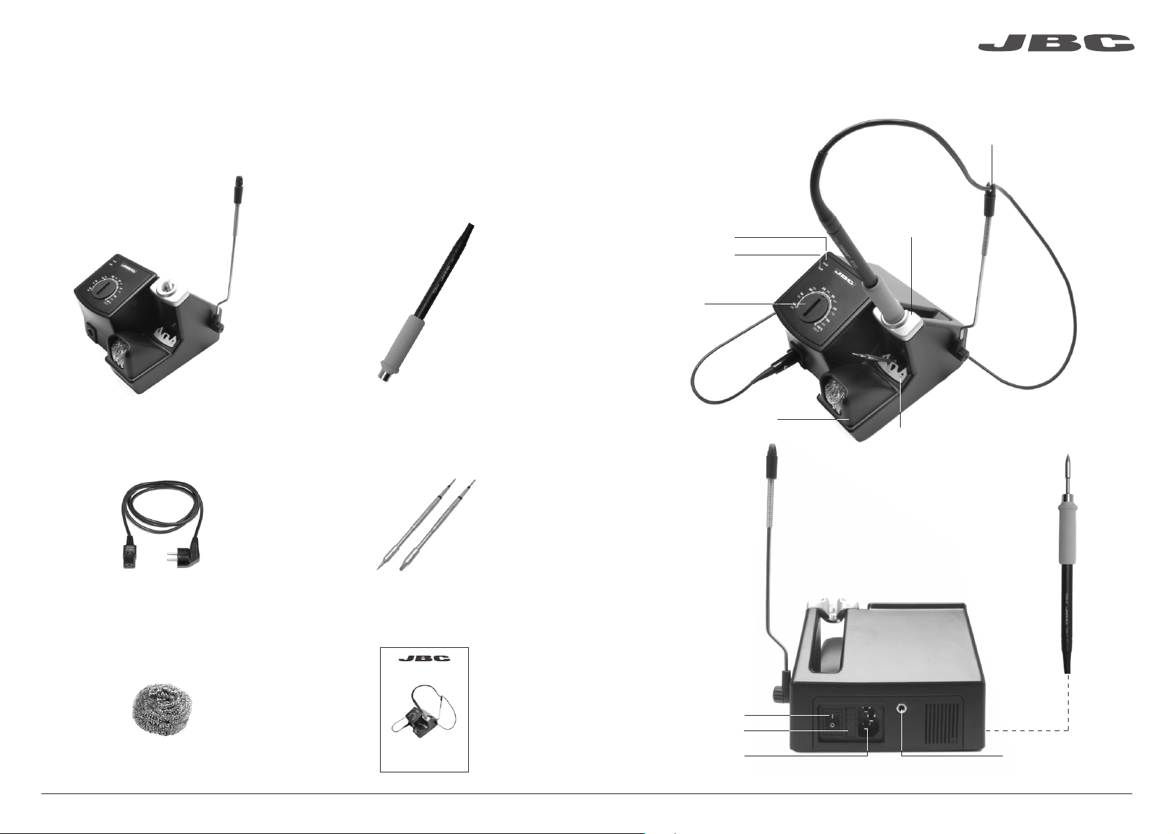
Packing List
The following items should be included:
www. jb ctools. co m
Features
Cable collector
Control Unit ............................................... 1 unit
Ref. BT-1A (120V)
BT-2A (230V)
BT-9A (100V)
Power Cord ................................................ 1 unit
Ref. 0009417 (100V/120V)
0009401 (230V)
General Purpose Handle ..................... 1 unit
Ref. T245-A
Cartridges ................................................. 2 units
Ref. C245906 (x1)
C245907 (x1)
Green LED
(IN USE)
Yellow LED
(SLEEP)
Dial
Tip Cleaning System
Stand
Quick Tip Changer
General Purpose Handle
Ref. T245-A
Brass Wool ................................................. 1 unit
Ref. CL6210
Manual ......................................................... 1 unit
Ref. 0008865
www.j bct ools .co m
Main switch
Fuse
Soldering Station
Ref. BT-A
Power Socket
Equipotential connection
2 3
Page 3
www. jb ctools. co m
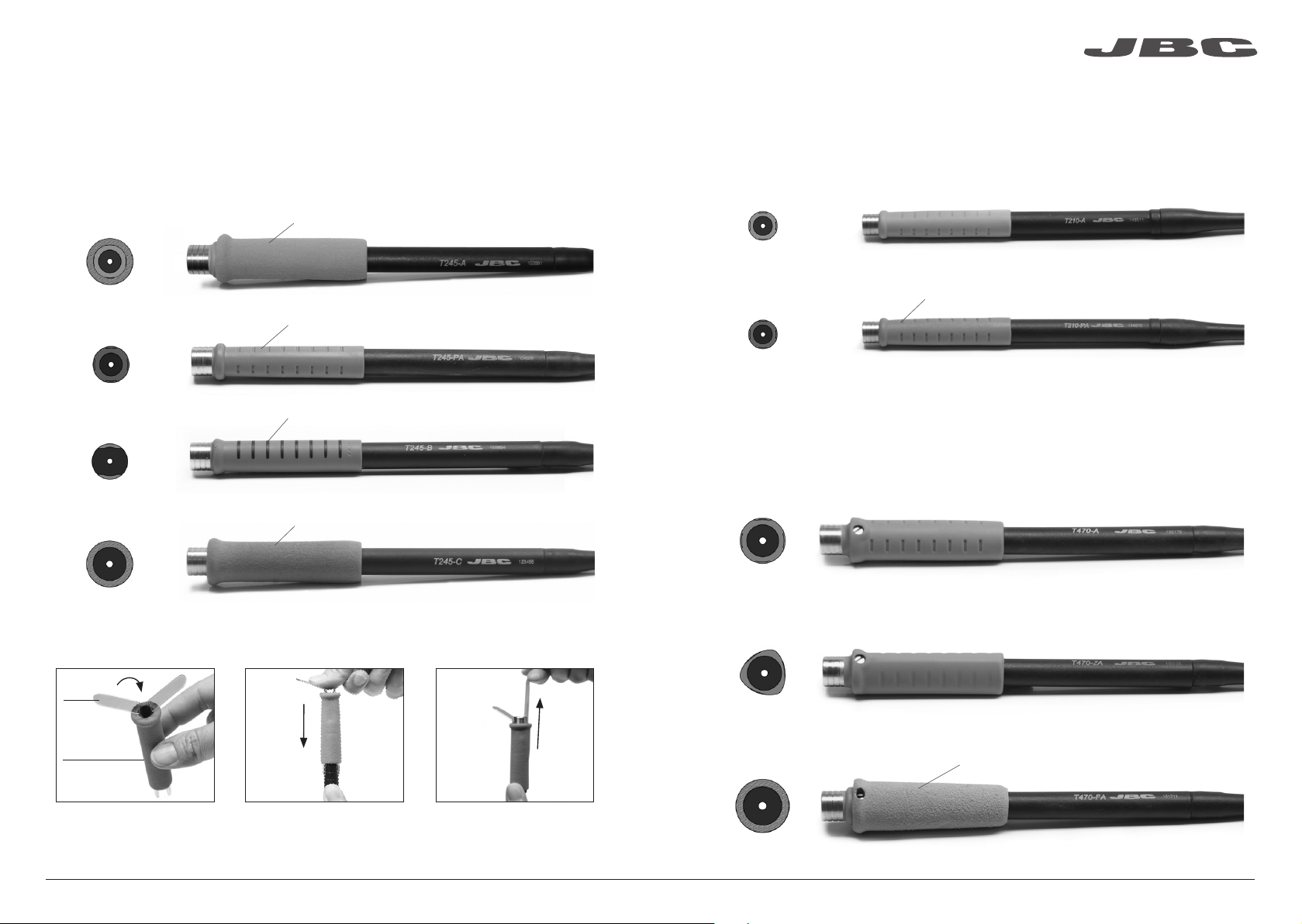
Compatible Handles
For general use
Works with C245 Cartridge range
General Purpose Handle
Ref. T245-A
Blue Handle
Ref. T245-PA
Non-slip Handle
Ref. T245-B
Soft Thermal Insulator Handle
Ref. T245-C
Soft foam (Ref. 0016057)
Blue grip to easily distinguish it from other handles
Non-slip soft touch
Soft foam (Ref. 0016057)
For precision use
Works with C210 Cartridge range
Precision Purpose Handle
Ref. T210-A
Blue Precision Handle
Ref. T210-PA
Blue grip to easily distinguish it from other handles
For greater demands
Important: Only work with C245 cartridges when used with a CD station.
For intensive soldering jobs requiring continued high thermal power. They feature good thermal
insulation and a screw which fixes the cartridge and prevents its rotation.
HD Purpose Handle HD Purpose Handle + 3m cable
Ref. T470-A Ref. T470-SA
Tri-lobed HD Handle
Easily replace the Grips for T245-A and T245-C using the slip-on tabs (Ref. 0016057 Supplied with
4 grips).
1. Inserting tabs 2. Inser ting handle
tabs
new grip
Put the slip-on tabs into the
new grip.
Slide the grip with the tabs
onto the handle.
Note: All models are supplied with a 1.5 m cable.
3. Removing tabs
To remove the tabs, hold the
grip and pull.
Ref. T470-ZA
For better handling of the tool.
Thermal Insulator HD Handle Thermal Insulator HD Handle + 3m cable
Ref. T470-FA Ref. T470-MA
Foam
Note: All models are supplied with a 1.5 m cable except those specified with 3 m.
4 5
Page 4

ø 1
ø 1,5
ø 3,5
Quick Tip Changer
www. jb ctools. co m
Operation
Save time and change cartridges safely without switching the station off.
1. Removing 2. Inserting 3. Fixing
B
Place the handpiece in the
extractor and pull to
remove the car tridge.
*Important
It is essential to insert the cartridges as far as the mark for a proper connection.
Mark
Place the handpiece on top
of the new cartridge and
press down slightly.
Use the holes for fixing the
cartridge* as follows:
A. For straight C210.
B. For curved C210.
C. For C245.
C
A
Compatible cartridges
The BT stations work with C245 cartridges and T245/T470 handpieces or C210 cartridges with T210
handpieces. Find the model that best suits your soldering needs in www.jbctools.com
B
Round Chisel Round
bent
Bevel
A
Special models
The LEDs indicate the station’s different working
modes.
1. Station wi thout a tool connected: The
green IN USE light flashes with the sequence
(- - -- --).
2. Tool out of the support: The green IN USE
light is permanently lit, indicating that the soldering
iron tip is at working temperature.
3. Tool in the support (sleep mode): The yellow
SLEEP light is permanently lit.
In order that the tool goes into sleep mode, the tool
must be in its support and the programmed sleep
temperature must be less than the temperature
on the dial or the prefixed temperature.
4. Station with previously fixed temperature.
(Only for users of the AC console).
Soldering iron out of support:
- If the dial is above the prefixed temperature,
the green IN USE light is lit the majority of the
time, switching off briefly at regular intervals
___
___
).
(
- If the dial is below the prefixed temperature,
the green IN USE light is off the majority of
the time, lighting up briefly at regular intervals
(- - -).
- If the dial is at the prefixed temperature, the
green light is permanently lit.
Errors
When the handpiece or the cartridge is in an
open circuit, the green IN USE light flashes with
the sequence (- - - - - -).
When the handpiece or the cartridge is in a short
circuit, the green IN USE light flashes with the
sequence (- - - - - - - - -).
If any of the above mentioned causes is corrected,
the station will start working automatically.
If the station is used continually in a overloaded
condition for a period of time, the system will
stop and both leds will flash simultaniusly. Switch
station off and on to reset and review the soldering
application.
Yellow LED
(SLEEP)
Dial
Green LED
(IN USE)
AC Console
The original parameters of control unit can be
modified using the AC console.
It is necessary to connect the console AC with
software revision 7.0 or later to the BT in order
to configure it (consult JBC for console software
updates).
Previous versions only allow for readin g of
counters and do not allow for modification of
parameters
Configuration possible:
- Fixing the working temperature.
- Selection of temperature units ºC or ºF.
- Modification of sleep temperatures and standby
times.
- Adjustment of temperature.
- Reset the parameters back to factory settings.
- Read-out data:
- Working hours.
- Sleep cycles and sleep hours.
- Cartridge and iron changes.
- Program version.
6 7
Page 5

Maintenance
www. jb ctools. co m
Safety
Before carrying out maintenance, always allow the equipment to cool.
- Clean the station screen with a glass cleaner
or a damp cloth.
- Use a damp cloth to clean the casing and
the tool. Alcohol can only be used to clean
the metal parts.
- Periodically check that the metal parts of
the tool and stand are clean so that the
station can detect the tool status.
- Maintain tip surface clean and tinned prior
to storage in order to avoid tip oxidation.
Rusty and dirty sur faces reduce heat
transfer to the solder joint.
- Periodically check all cables and tubes.
- Replace a blown fuse as follows:
1. Pull off the fuse holder and remove the
fuse. If necessary use a tool to lever it off.
2. Press the new fuse into the fuse holder
and replace it in the station.
Clean
periodically
It is imperative to follow safety guidelines to prevent electric
shock, injury, fire or explosion.
- Do not use the units for any purpose other than soldering or rework. Incorrect use may cause fire.
- The power cord must be plugged into approved bases. Be sure that it is properly grounded
before use. When unplugging it, hold the plug, not the wire.
- Do not work on electrically live parts.
- The tool should be placed in the stand when not in use in order to activate the sleep mode.
The soldering tip, the metal part of the tool and the stand may still be hot even when the station is
turned off. Handle with care, including when adjusting the stand position.
- Do not leave the appliance unattended when it is on.
- Do not cover the ventilation grills. Heat can cause inflamable products to ignite.
- Use a “non residue” classified flux and avoid contact with skin or eyes to prevent irritation.
- Be careful with the fumes produced when soldering.
- Keep your workplace clean and tidy. Wear appropriate protection glasses and gloves when
working to avoid personal harm.
- Utmost care must be taken with liquid tin waste which can cause burns.
- This appliance can be used by children over the age of eight and also persons with reduced
physical, sensory or mental capabilities or lack of experience provided that they have been given
adequate supervision or instruction concerning use of the appliance and understand the hazards
involved. Children must not play with the appliance.
- Maintenance must not be carried out by children unless supervised.
- Replace any defective or damaged pieces. Use original JBC spare parts only.
- Repairs should only be performed by a JBC authorized technical service.
8 9
Page 6

Exploded View
www. jb ctools. co m
10 11
Page 7

Specifications
BT-1A 120V 50/60Hz. Input fuse: 2A. Output: 24V
BT-2A 230V 50/60Hz. Input fuse: 1A. Output: 24V
BT-9A 100V 50/60Hz. Input fuse: 2A. Output: 24V
- Weight: 2.6 Kg (5.7 lb)
- Dimensions: 162 x 153 x 115 mm
- Power: 75W
- Temperature range: 100-450°C (200-850 ºF) (±5%)
Complies with CE standards
ESD protected housing “skin effect”
Warranty
JBC’s 2 year warranty covers this equipment against
all manu facturing defects, including the replacement of
defective parts and labour.
Warrant y does not cover product wear due to use or
mis-use.
In order for the warranty to be valid, equipment must
be returned, postage paid, to the dealer where it was
purchased.
This product should not be thrown in the garbage.
In accordance with the European directive 2012/19/EU, electronic equipment at the end of their life
must be collected and returned to an authorized recycling facility.
www.jbctools.com
0008865-1215
 Loading...