

Page 1

Index Page
English 1
Español 25
Français 49
Deutsch 73
Italiano 97
0780448-0
AM 6000
REWORK STATION
Instructions manual
CE Version
Page 2
ENGLISH
1
We appreciate the confidence you have placed in JBC in purchasing this station.
It is manufactured to the most stringent quality standards in order to give you the
best possible service. Before turning on your station, we recommend you to read
these instructions carefully.
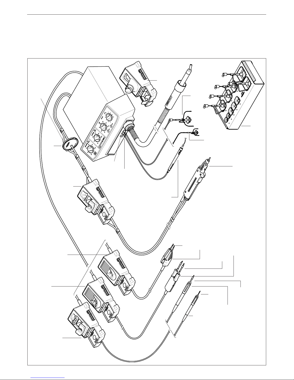
Extractor stand
Ref.0932845
Tripod 20
Ref.0932050
Tripod 40
Ref.0932250
Soldering iron stand
AD 8200
Ref.0268200
Desoldering iron
DR 5600
Ref.5600000
* Handpiece 2210
Ref.2210000
Cartridges 2245
Pick & Place
MP 2260
Ref.2260000
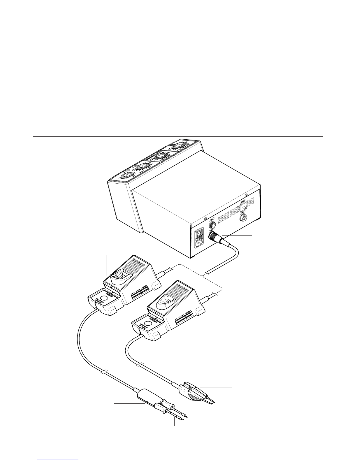
AM 6000
rework station
Pick & Place and extractors
vacuum selection
Heater stand JT 8700
Ref.0828700
Equipotential
terminal
* These elements are not
supplied with the station
Spare filters
Ref.0781046
* Hot tweezers stand
PA 8120
Ref.0748120
* Hot tweezers stand
PA 8110
Ref.0748110
Handpiece 2245
Ref.2245000
* Hot tweezers
PA 4200
Ref.4200000
* Cartridges for the hot tweezers PA 4200
* Micro hot tweezers
PA 1200
Ref.1200000
* Cartridges 1200
Desoldering iron stand
DR 8500
Ref.0788500
External desoldering air filter
Ref.0821830
Page 3

2
ENGLISH
SPECIFICATIONS
The AM 6000 is a rework station for through-hole and
SMT boards.
- AM 6000 230V Ref. 6000200
It contains 4 modules which cover the main rework
tasks:
- Hot air for desoldering any size of SMD
components.
The station uses the exclusive JBC system,
based on protectors-extractors and hot-air flow,
which makes desoldering clean and quick,
concentrating the heat on the IC, and protecting
the rest of the circuit at the same time.
A medium-sized SMD can be desoldered in less
than 20 seconds.
- Desoldering SMTs and cleaning of through-hole
components and pads by using the desoldering
iron DR 5600, which contains a self-contained
vacuum pump.
- Pick & Place MP 2260 pencil by suction to aid
components positioning.
- Soldering of all types of components, with the
swift response, power and temperature recovery
of the Advanced series. You can connect the
Advanced 2010, 2210, 2045 or 2245 handpieces
and the hot tweezers PA 1200 or PA 4200.
The station’s components
- Control Unit with 900 W heater
- Handpiece 2245 Ref. 2245000
with the cartridge 2245-003 Ref. 2245003
- Desoldering iron DR 5600 Ref. 5600000
with the tip 5600-003 Ref. 5600003
- Pick & Place MP 2260 Ref. 2260000
Accessories for the heater:
- Heater stand JT 8700 Ref. 0828700
- Extractor stand Ref. 0932845
- Set of 5 protectors (Fig. 1, page 128)
- Set of 5 extractors (Fig. 2, page 128)
-2 tripods for the protectors (Fig. 1, page 128)
- Set of 4 suction cups Ref. 0930110
-3 nozzles
In order to make the nozzles removal easier, the
stand has a special bushing.(Fig. 3, page 128).
- Suction tube with connectors Ref. 0932330
- Pedal with cable and connector Ref. 0964551
Accessories for the handpiece:
- Soldering iron stand AD 8200 Ref. 0268200
Accessories for the desoldering iron:
- Desoldering iron stand DR 8500 Ref. 0788500
- External desoldering air filter Ref. 0821830
- Spare filters Ref. 0781046
- Set of accessories Ref. 0780593
Accessories for the Pick & Place:
- Set of suction cups Pick & Place Ref. 0940163
- Set of straight needles Ref. 0901546
- Set of bent needles Ref. 0861660
- Instruction manual Ref. 0780448
The AM 6000 station has the following
complementary products:
- Handpiece 2010 Ref. 2010000
- Handpiece 2210 Ref. 2210000
- Handpiece 2045 Ref. 2045000
- Micro hot tweezers PA 1200 Ref. 1200000
- Hot tweezers PA 4200 Ref. 4200000
Page 4
ENGLISH
3
OPERATION
Description of controls
- PEDAL:
Hot air is produced when it is held down.
Releasing it the heater is disconnected,
though the turbine continues to operate until
the air temperature falls below 100°C.
- BUTTONS:
Activates or desactivates the hot-air flow. After a
function-time of two minutes the hot-air flow
switches automatically off.
The red light indicates, that the heating element
is functioning. A malfunction is indicated by the
pulsing of the red led.
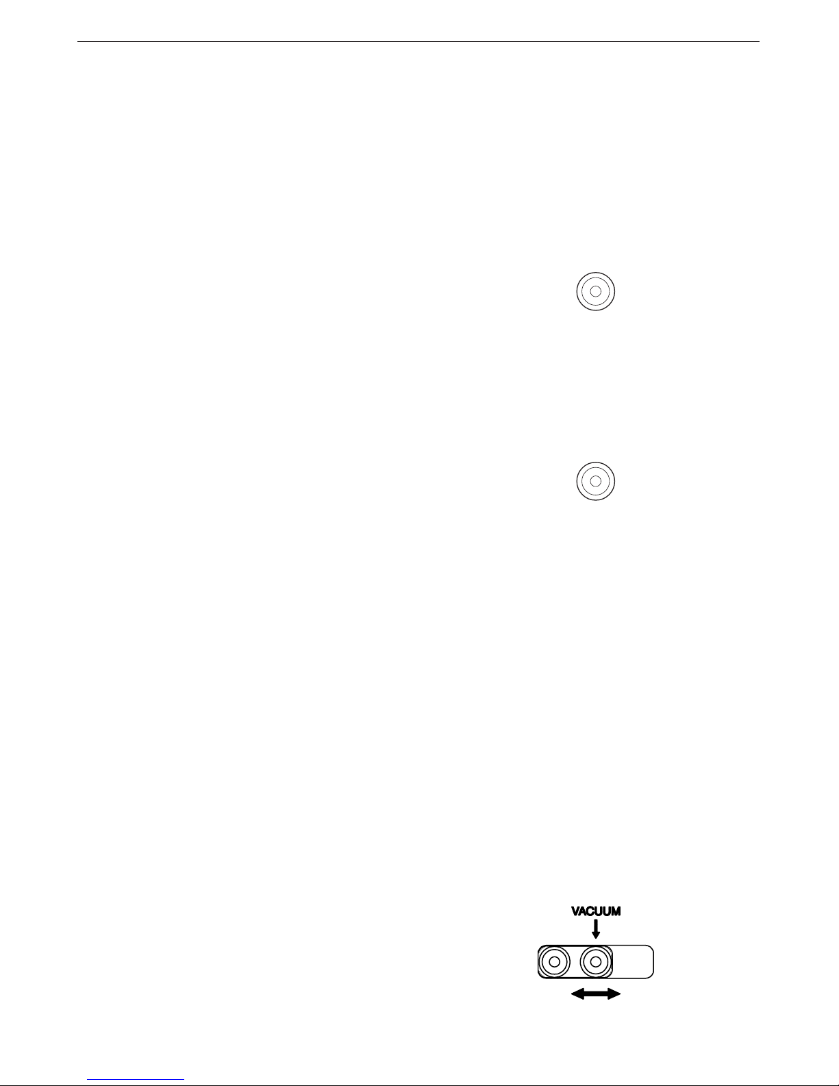
On/off switch for the self-contained suction pump.
The yellow light of the switch indicates that the
self-contained vacuum pump is activated.
- CONTROLS:
TEMPERATURE
Allows fixing the temperature of the heater
between 150 and 455°C. The selected
temperatures are reference values which may
change depending on the distance between
the heating element and the nozzle.
Allows fixing the temperature of the soldering
and desoldering iron between 100 and 371°C.
AIR FLOW
This enables the air flow to be set on a scale
from 1 (corresponding to the lowest setting
of 6 l/min) to 10 (corresponding to the highest
of 45 l/min).
- VACUUM SELECTOR:
Two vacuum inlets avalaible, being active
the one that coincides with the arrow.
HEAT
VACUUM
Control Unit technical specifications
- Maximum power soldering iron 50W
- Maximum power desoldering iron 75W
- Power heating unit 900W
- Temperature selection of the soldering part :
100 to 371°C (±5%)
- Temperature selection of the desoldering part:
100 to 371°C (±5%)
- Temperature selection hot air:
150 to 455°C (±5%)
- Air flow regulation: 6-45 l/min
- Self-contained vacuum pump for holding ICs
- Station's maximum power: 1150W
- ESD protected housing.
Typical surface resistance: 105-1011Ohms/square
- Complies with CE standards on electrical safety,
electromagnetic compatibility and antistatic
protection.
- Equipotential connector is earth connected to the
plug feed of the station.
- Weight of complete unit: 17.6 kg
- In the SOLD. connector you can only connect
handpieces 2010, 2210, 2045 and 2245 and the
hot tweezers PA 1200 and PA 4200.
- In the DESOLD. connector you can only connect
the desoldering iron DR 5600.
Safety measures
- Incorrect use of this tool may cause fire.
- Be cautious when using the tool in places
where inflamable products are stored.
- Heat can fire up inflamable products even
when they are not at sight.
- Do not use when the atmosphere is explosive.
- Place the tool back on its stand in order to let
it cool down before you store it.
Page 5

4
ENGLISH
- Use the pedal or the HEAT button to start the
self-contained hot-air pump, directing it with a
circular movement at the component terminals
and taking care to distribute the heat evenly.
- When the soldering flux turns liquid the extractor
will automatically lift the component.
B) Extractor:
- Select extractor size in function of the IC to be
desoldered. Use the VACUUM button to start
the pump.
DESOLDERING PROCEDURE WITH THE
HEATER
We would also recommend the use of the nozzles of
larger diameter, reserving the smallest one (diam. 4
mm) for desoldering small components such as
resistors, condensers and the like, bearing in mind
that with this small nozzle the concentration of heat
is greater and care must be taken to avoid burning
the printed circuit; we recommend keeping below a
temperature of 350 °C and air flow of 6.
Depending on the size of the integrated circuit to be
desoldered, you will have to use:
A) Protector + tripod.
B)Extractor.
C) Tripod.
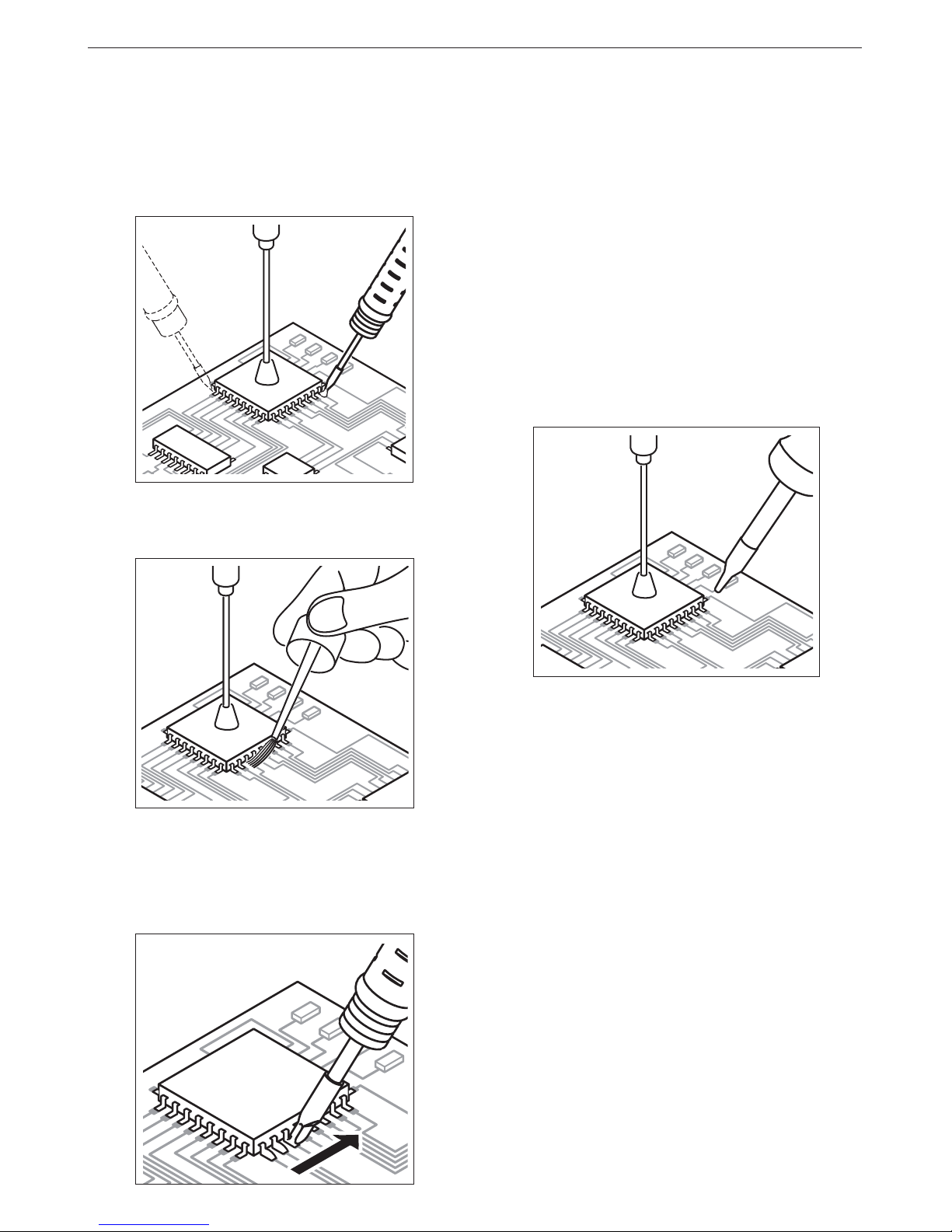
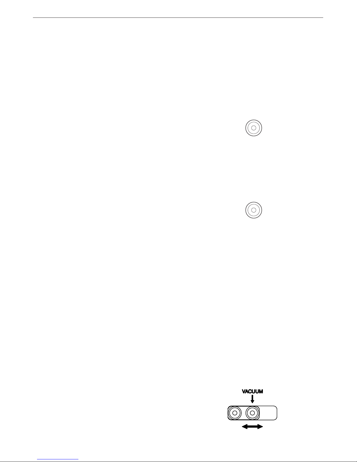
A) Protector + tripod:
- Select protector and tripod size in function of
the IC to be desoldered and place it over the
component.
- Use the VACUUM button to start the pump and
then fit the tripod. Press the sucker down until it
sticks onto the component.
Page 6

ENGLISH
5
There are different models of protectors and
extractors as accessories.
The measurements of all the extractors and
protectors are given on page 128 of instructions
manual.
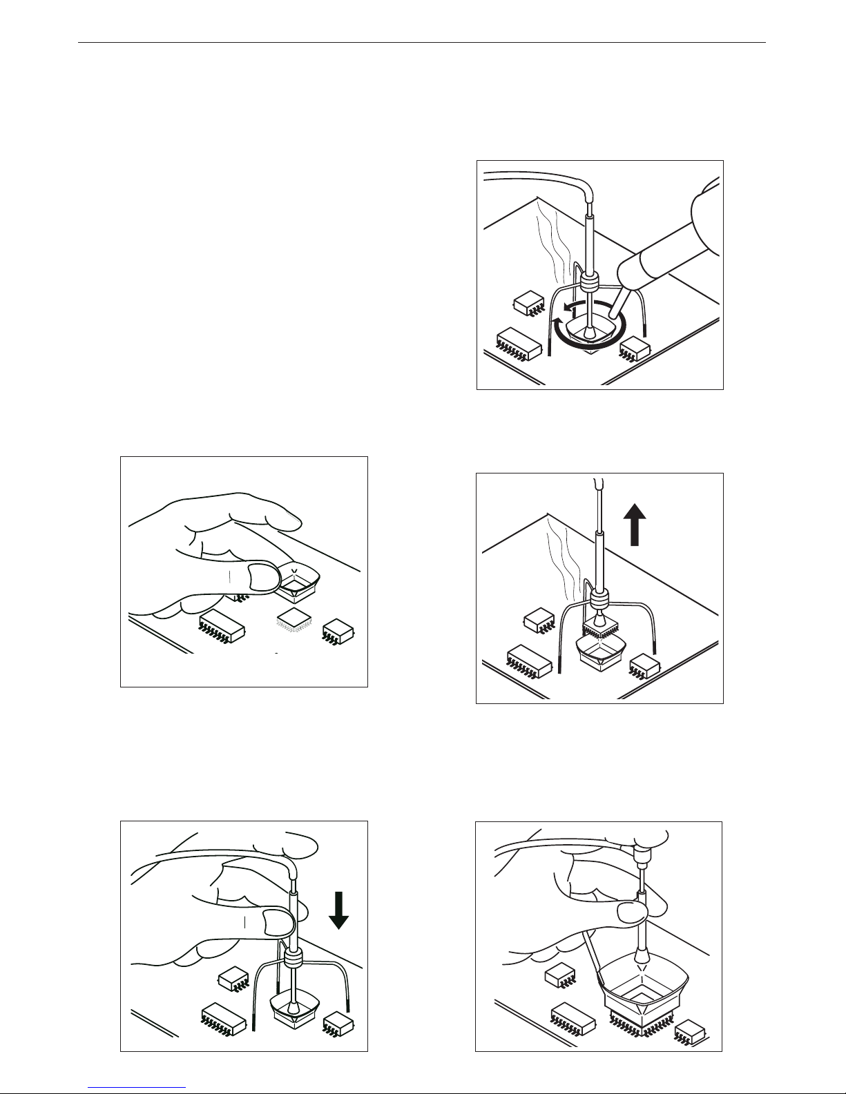
C) Tripod:
For small components for which an extractor
cannot be used, we recommend use of tripod 20
Ref. 0932050, as shown in the figure.
Use the tripod 40 Ref. 0932250 for larger integrated
circuits.
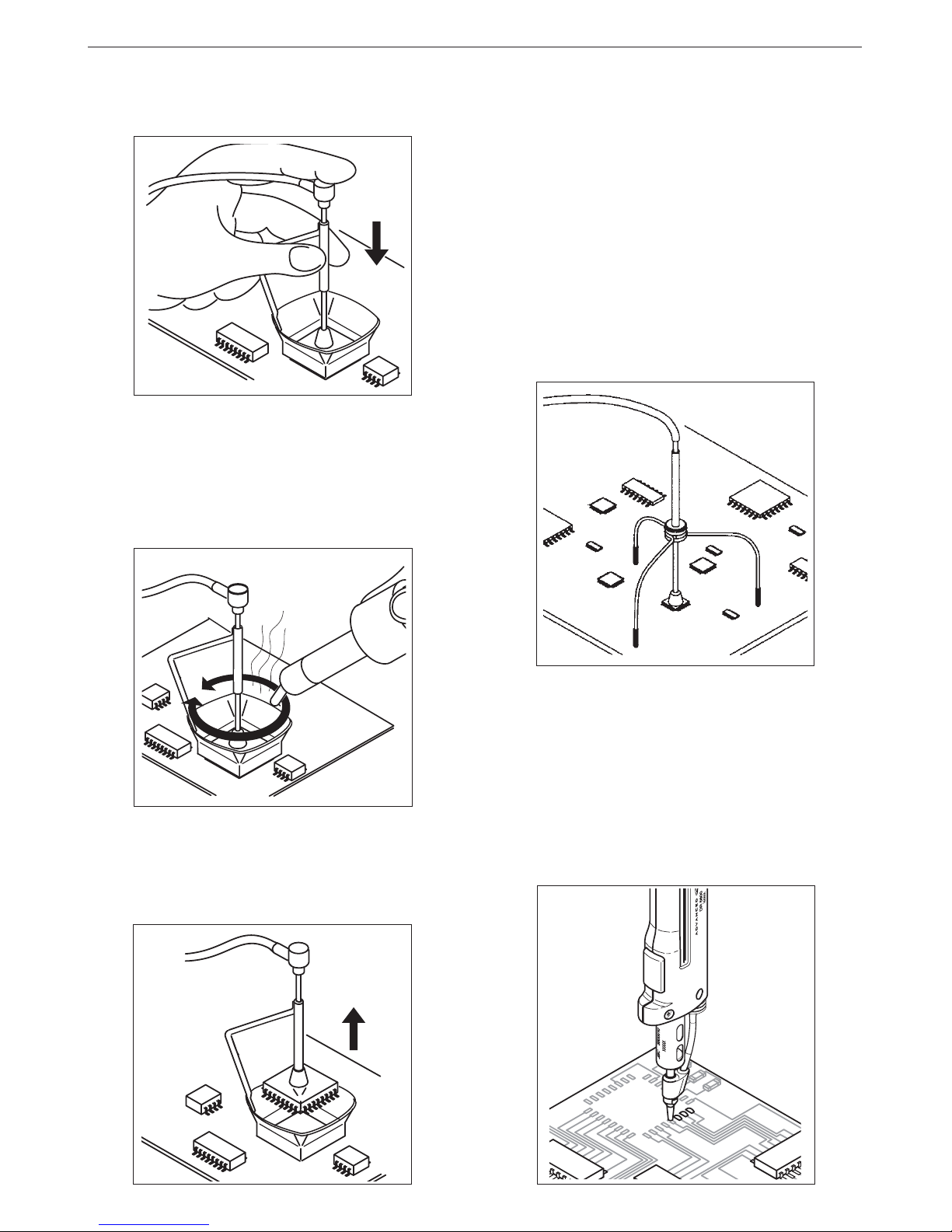
SOLDERING PROCEDURE
1 After desoldering the component, any solder
left on the printed circuit should be removed
with our desoldering iron DR 5600 ref. 5600000.
- Fit the extractor and press the sucker down until
it sticks onto the component.
- Use the pedal or the HEAT button to start the
self-contained hot-air pump, directing it with a
circular movement at the component terminals
and taking care to distribute the heat evenly.
- When the soldering flux turns liquid the extractor
will automatically lift the component.
Page 7
6
ENGLISH
Soldering Iron 2210 ref. 2210000 for great
precision tasks, like SMD solders, etc.
Soldering Iron 2245 ref. 2245000 for general
soldering tasks in professional electronics.
These soldering irons have a wide range of
cartridges with different models of tips. The
cartridge 2245-009 and 2245-010 are specially
designed for soldering SMD circuits of the
QFP and PLCC types.
Solder wire with a diameter of between 0.5 and
0.7 mm should be used.
6 Depending on the nature of the component to be
soldered, use soldering paste together with our
hot air station TE 5000, which gives very
accurate air-flow regulation, between 4 and 11
l/min.
2 Place the component or printed circuit with
the Pick & Place MP 2260 ref. 2260000.
3 When the component is correctly placed, solder
its pins.In the case of integrated circuits of the
Flat Pack type, first solder one pin of every IC
angle to fix it in place in the circuits.
4 Apply Flux FL 9582 ref. 0046565 in pads and
leads.
5 Solder the remaining pins. For this we
recommend to use our soldering irons of the
Advanced series, which are available in two
different models:
Page 8
ENGLISH
7
MAINTENANCE
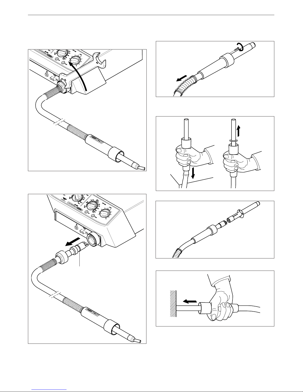
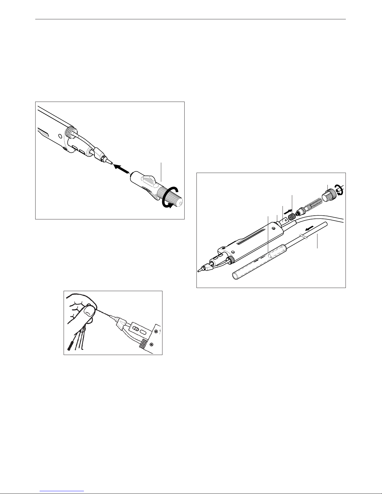
Exchanging the heater.
Use a wrench to unscrew the cover.
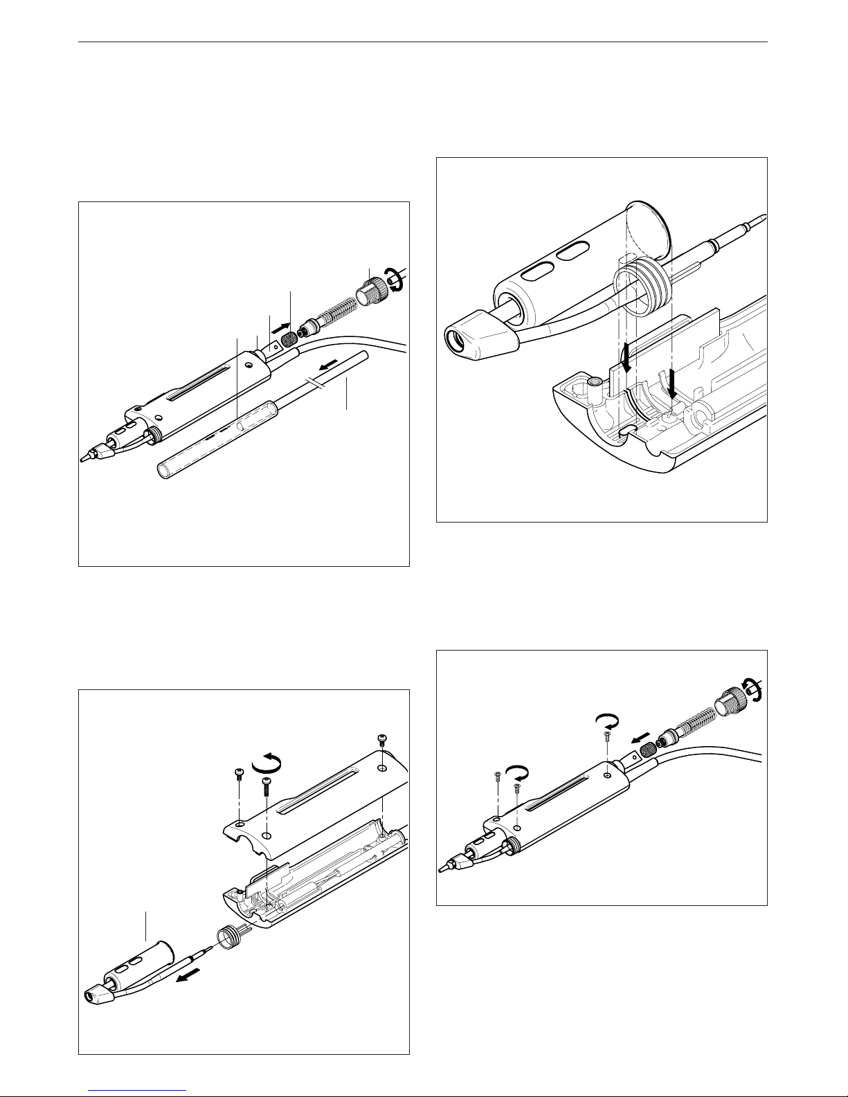
Exchanging the resistor from the heater.
1. Move back the spring. Untighten the screws.
Follow this process inverted to re-connect the heater.
Move back the spring and the cover. Pull the
connector from the socket to disconnect the heater
from the station.
2. To take out the resistor, press down the lower
part of the heater on a fixed surface.
4. Connect the new resistor, pushing it’s extreme.
5. Fix the screws tightly to avoid air-loss which
could reduce the resistor’s lifetime. Finally put
the spring back in it’s place.
3. Separate the resistor from the heater’s cable.
O-ring ø17 x ø1,8
Page 9
8
ENGLISH
OPERATING INCIDENTS
The suction cup does not adhere to the
component.
Deficient aspiration, Vacuum.
1 Verify if the suction cup is well placed and in
perfect condition.
Possible errors
In the case of malfunction, the control unit
interrupts the connection.
Following a list of the most common
malfunctions:
- Power failure.
Check for blown fuses.
- The temperature will not rise.
Possible causes:
· Heating element open.
· In case of a long low-power period.
- No reading from the thermocouple.
Possible cause: open thermocouple.
- Insufficient air flow which causes an excesive
rise of the heating temperature.
Before recuperating this type of error you must
wait until the temperature goes down.
Possible causes: leaking or blocked air conducts
or faulty self-contained air pump.
Filter
Ref. 0861800
2 Check the incoming air filter in the interior of
the station and replace it if dirty or obstructed.
- Faulty reading of the rotationsmeter of the selfcontained air pump.
Possible causes: air pump damaged or faulty
function of the optical sensor circuit.
To recuperate any of these errors actuate the
general switch at the back of the station, the
pedal should not be pushed at this moment.
Page 10
ENGLISH
9
DESOLDERING IRON DR 5600
The AM 6000 station includes the following:
- Desoldering iron DR 5600 ref. 5600000 with the
tip 5600-003 ref.5600003.
Power desoldering iron: 75W.
- Desoldering iron stand DR 8500 ref. 0788500.
- External desoldering air filter ref. 0821830.
- Set of accessories ref. 0780593 with tips for the
desoldering iron: 5600-003, 5600-004 and 5600-
005.
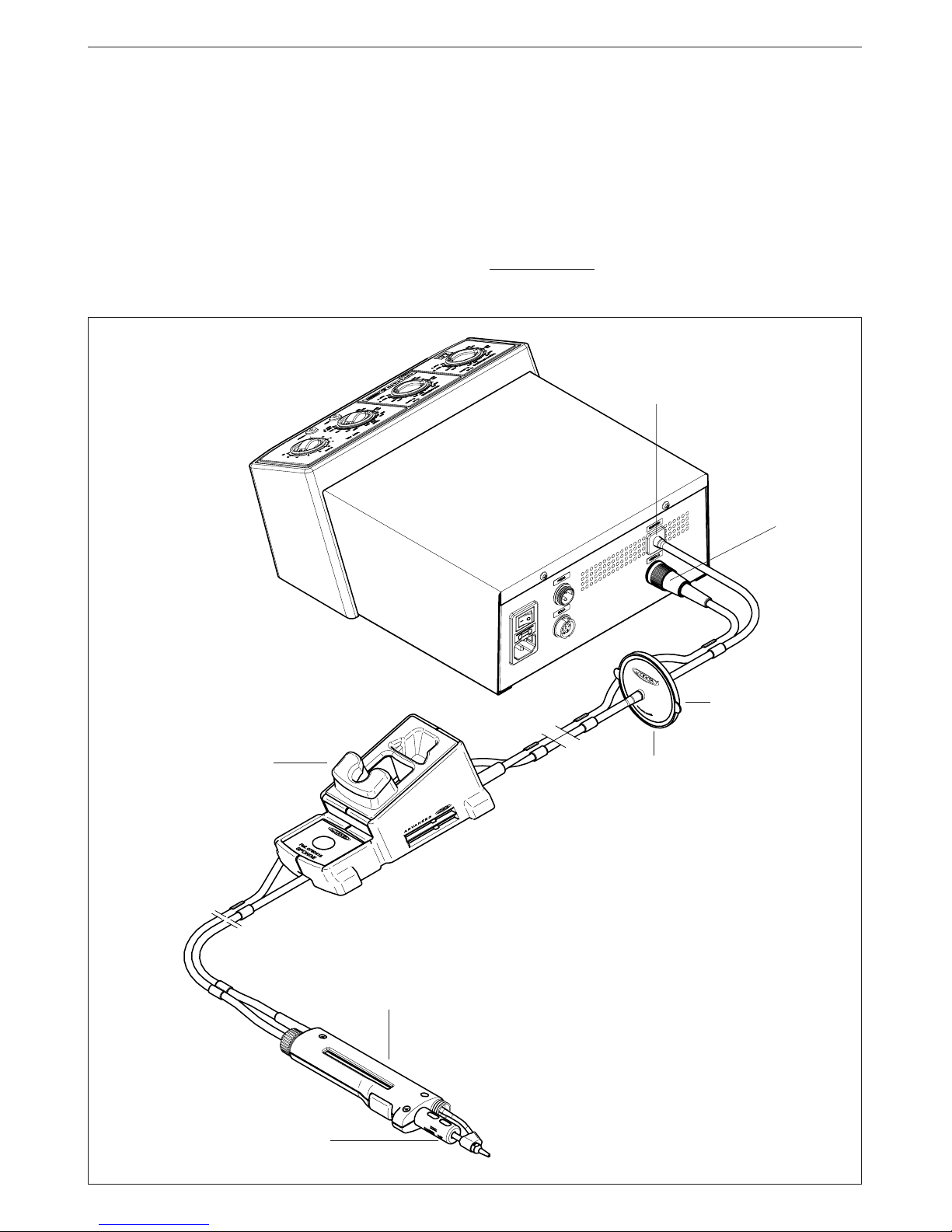
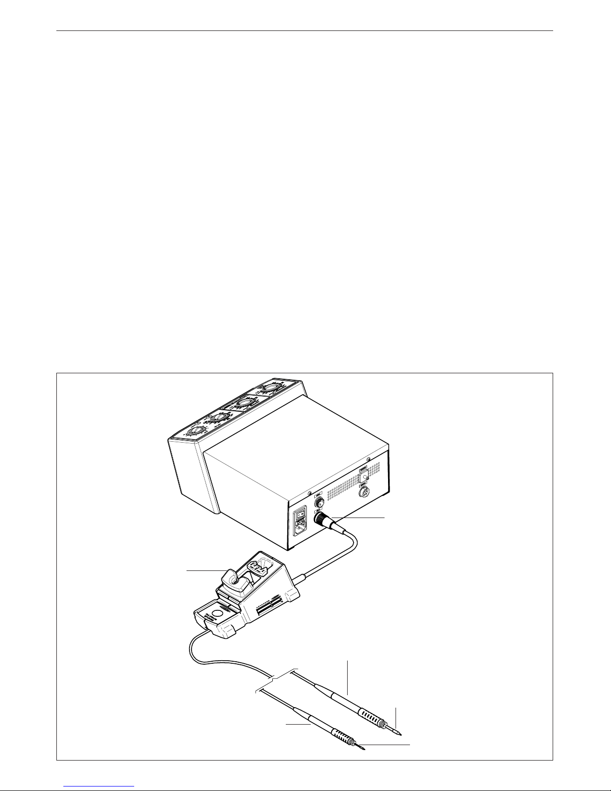
The desoldering iron is connected to the station
following the below procedure:
The cable connection of the desoldering iron is
connected to the plug in the desoldering iron stand
DR 8500 and the vacuum hose is connected to the
external desoldering air filter, which is connected to
the vacuum connection SUCTION of the station. The
cable connection of the desoldering iron stand is
plugged into the terminal DESOLD of the station.
Very important, it is essential to connect the mentioned
filter to prevent from damaging the vacuum pump.
Desoldering iron stand
DR 8500
Ref.0788500
Desoldering iron
DR 5600
Ref.5600000
Spare filters
Ref.0781046
Heating element
Ref.5600010
Vacuum inlet
SUCTION
Desoldering
connector
DESOLD
External desoldering air filter
Ref.0821830
Page 11
10
ENGLISH
OPERATION
LED lights
Red LED -ON- when lit, it indicates that the station is
plugged in the mains.
Green LED -READY- when lit, it indicates that the
system is ready and correctly set for working.
The green led light is on after a few seconds, is the
time needed to carry on the self-checking system.
The green light is pulsing when the desoldering iron
is in sleep mode.
If the green led is not lit, the reason why, will be one
of the following:
1. The desoldering iron is not plugged in.
2. The maximum available power has been
exceeded for too long - e.g. in a very thick
desoldering at the high repetition rates.
3. The desoldering heating element has a short
circuit or an open circuit.
4. Any other trouble preventing the system from
working properly.
The handpiece will reset itself automatically should
the cartridge short circuit or go open circuit.
Should the handpiece be subject to:
- An electrical surge or the cartridge has not been
fitted correctly.
Please turn the unit off and switch on again to reset.
When pressing the button of the desoldering iron
handle, one of the two leds in the area marked
SUCTION will light up:
Green light -SUCTION- indicates the correct
functioning of the desoldering iron.
Red light -SUCTION- indicates a blockade within
the vacuum circuit.
This can be caused by the following:
- The tip of the desoldering iron is blocked.
Sleep function
One of the Series Advanced features is that when
the desoldering iron is placed in the holder, the
temperature at the tip drops automatically to th e
sleep temperature. This function is only
possible because of the quick response time
which does not make the user realise the
temperature rise to reach the selected
temperature. Also by this, the oxidation of the
tinning of the tip is considerably reduced and
tip life is extended.
To indicate that the desoldering iron is in sleepmode, the green led starts pulsing. These
parameters can be modified using the Console
AC 2600 Ref. 2600000.
In order to take advantage of the above
mentioned feature and as a security measure,
it is necessary to place the desoldering iron
on stand when the iron is not being used.
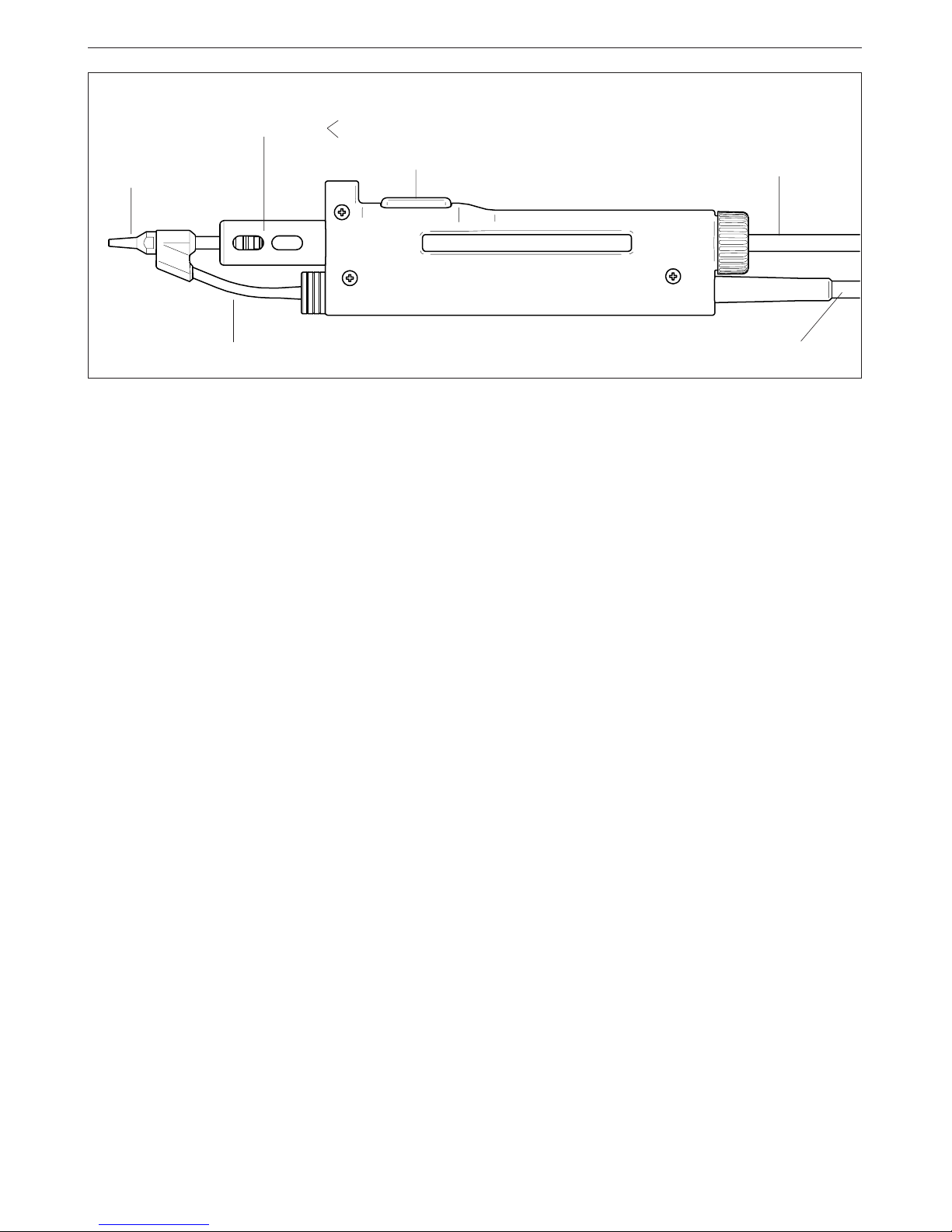
DR 5600 Ref.5600000
Desoldering tip
Heating element
Pushbutton vacuum pump
Vacuum hose
Desoldering iron cable
Solder tin deposit
Metal
Glass
- The solder tin deposit is full.
- The filter of the desoldering iron is dirty.
- The station’s external desoldering air filter is
dirty.
Only for users of AC 2600 console ref. 2600000.
If you lock the working temperature thanks to the
console, the green LED -READY- will remain on
while the dial is set at the locked temperature.
If the dial is not set at the locked temperature,
the green LED -READY- will be blinking. The
farther the dial will be set from the locked
temperature the slower the blinking pace will be.
Page 12
ENGLISH
11
RECOMMENDATIONS FOR USE
For soldering and desoldering
- Clean the contacts and the printed circuit to
be desoldered of dust or dirt.
- Preferably select a temperature below 350°C.
Excess temperature may cause the printed
circuit tracks to break loose.
- The tip must be well tinned for good heat
conduction. If it has been inoperative for any
length of time, it should be retinned.
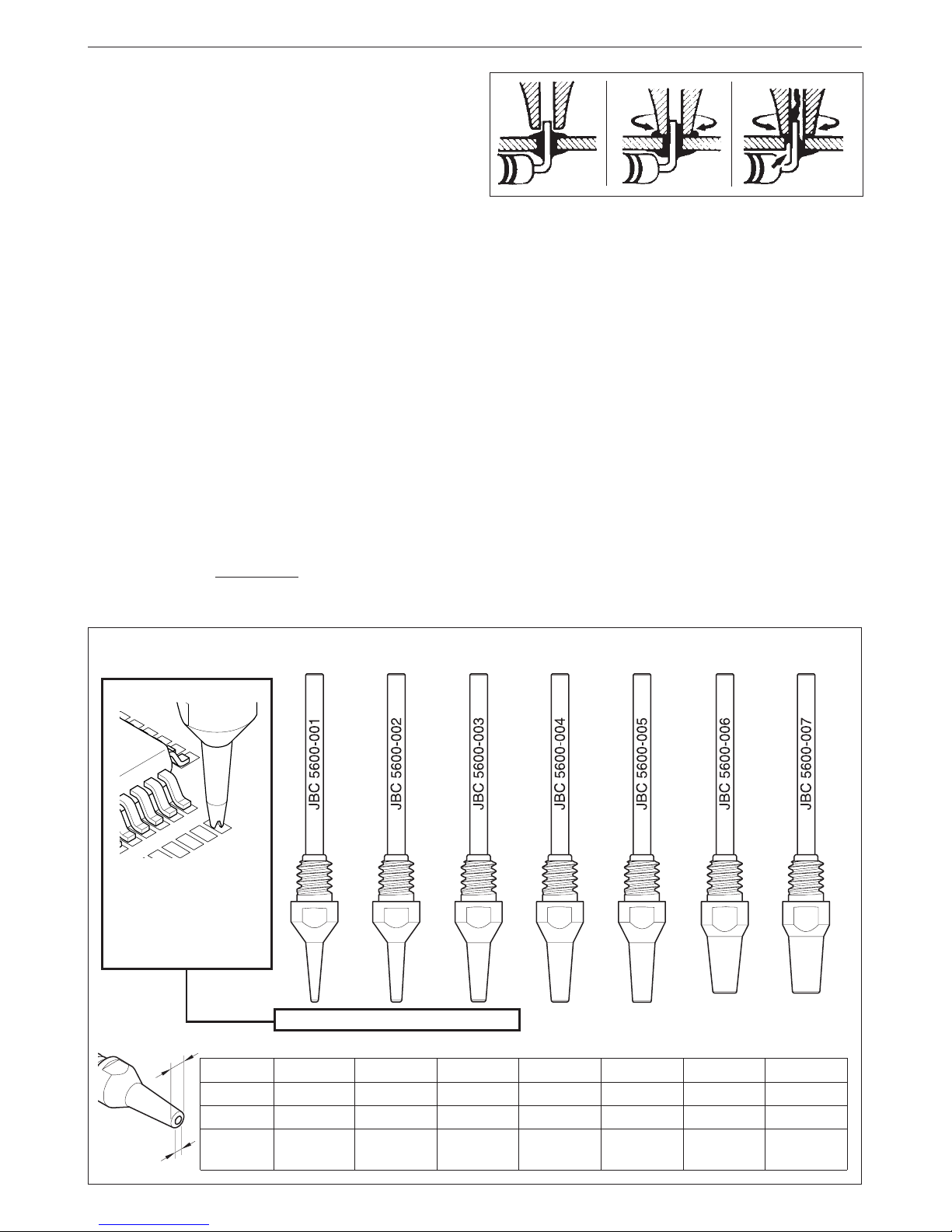
Desoldering process
Use the tip model with a larger diameter than the
pad to be desoldered, so as to achieve maximum
aspiration and thermal efficiency.
1 Apply the desoldering iron tip so that the
component terminal penetrates within its
orifice.
2 When the solder liquefies, start gently to rotate
the desoldering tip so that the component’s
terminal can be eased away from the sides.
3 Press then, not before, the vacuum pump
push-button just long enough to aspirate the
solder.
After pressing the desoldering key there is a
slight delay until the self-contained vacuum
pump stops, this is to make sure that the
vacuum circuit is completely empty.
If any solder remains are left on any terminal after
attempting to desolder it, resolder it with fresh
solder and repeat the desoldering operation.
1
2
3
DESOLDERING TIPS
These tips are
specially designed
to clean the pads.
Ref. 5600-001 5600-002 5600-003 5600-004 5600-005 5600-006 5600-007
5600
A ø (mm)
B ø (mm)
max. pin ø
(mm)
001 / 011
1.4
0.6
0.4
002 / 012
1.8
0.8
0.6
003 / 013
2.7
1
0.8
004
3.2
1.3
1.1
005
3.4
1.6
1.4
006
4.2
2
1.7
007
4.8
2.5
2.3
A ø
B ø
5600-012 5600-0135600-011
Page 13
12
ENGLISH
Change of desoldering tip
This operation should be done while the tip is hot,
at a minimum temperature of 250°C, so that any
tin left inside is in molten state.
- Unscrew the tip to be replaced, with the aid of
the spanner supplied.
- Fit the new tip, and tighten up with the spanner
to achieve a good air tightness.
To empty the solder tin deposit and change
the filter
For this, the lid needs to be unscrewed and first
the tin deposit and then its spiral must be removed
to clean the inner part of the deposit with a brush.
- The condition of the filter must be checked
and replaced if dirty or damaged.
- The deposit needs to be inserted with spiral
filter put into place. Then the whole must be
closed by screwing the lid shut.
Solder tin deposits
It can be chosen between two different deposit
types:
- Metal Ref. 0812630.
- Glass Ref. 0812620.
Lid
Brush
Ref. 0786640
Filter Ref.0780840
Deposit
Spiral
Ref. 0780550
Tip care
- The largest rod that fits in the tip hole should
periodically be passed through in order to
clean the intake tube.
- To clean the tips, use the sponge included
with the stand and check it is slightly moisted.
Only deionised water (car battery water)
should be used in order to wet the sponge.
If normal water was to be used, it is very likely
that the tip will become dirty due to the salts
dissolved within the water.
- Do not file the tips or use abrasive tools
which may damage the tip’s protective
surface coating and avoid knocking them
about.
- If the tip has been a long time without being
tinned, use a metal brush to remove any dirt
and oxid.
IMPORTANT: DO NOT press the pushbutton
vacuum pump while tinning the desoldering tip,
as the fumes given off by the flux would quickly
soil the ducts and filter of the air circuit.
Page 14
ENGLISH
13
- Place the new heating element. Check that
the right extremity of the upper part of the
heating element is inserted in the slot
located inside the body of the desoldering
iron (see drawing hereunder).
- Screw out the body of the desoldering
iron. Open up the body and remove the
heating element.
- Screw in the body of the desoldering iron.
Put the spiral and the filter back into the
deposit. Place the deposit inside the body
of the desoldering iron and screw in the
shut lid.
Lid
Brush
Ref. 0786640
Filter Ref. 0780840
Deposit
Spiral
Heating element
Ref. 5600010
Change of the heating element of the
desoldering iron (Ref. 5600010)
- To realize this operation, the lid needs to
be unscrewed and first the tin deposit and
then its spiral and filter must be removed
to clean the inner part of the deposit with
a brush.
Page 15
14
ENGLISH
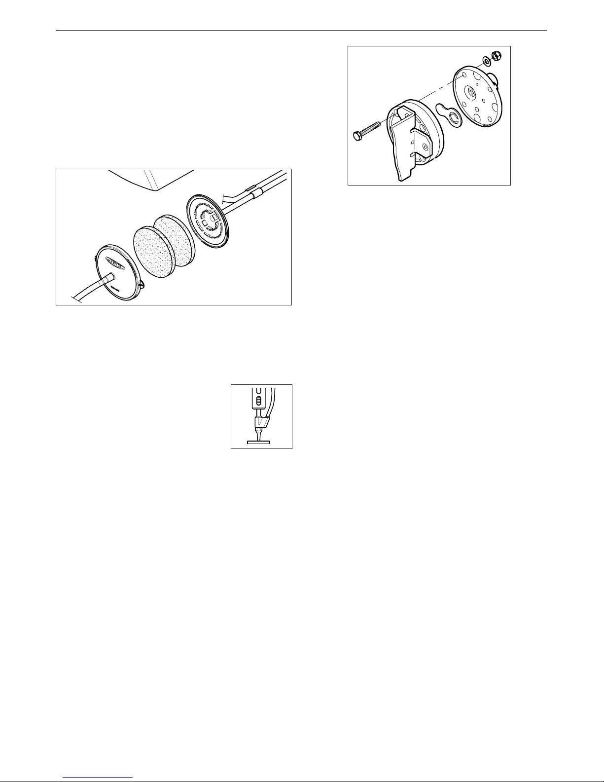
Cleaning the vacuum pump valve
Open the control unit as follow:
- Disconnect the control unit.
- Turn it upside down, remove the fixing
screws.
- Return the station to its normal position and
lift up the lid.
- Undo the four screws fastening the pump cover.
- Clean the valve with a cloth dampened in
alcohol. If it is too soiled, replace it with new
one. Ref. 0982970.
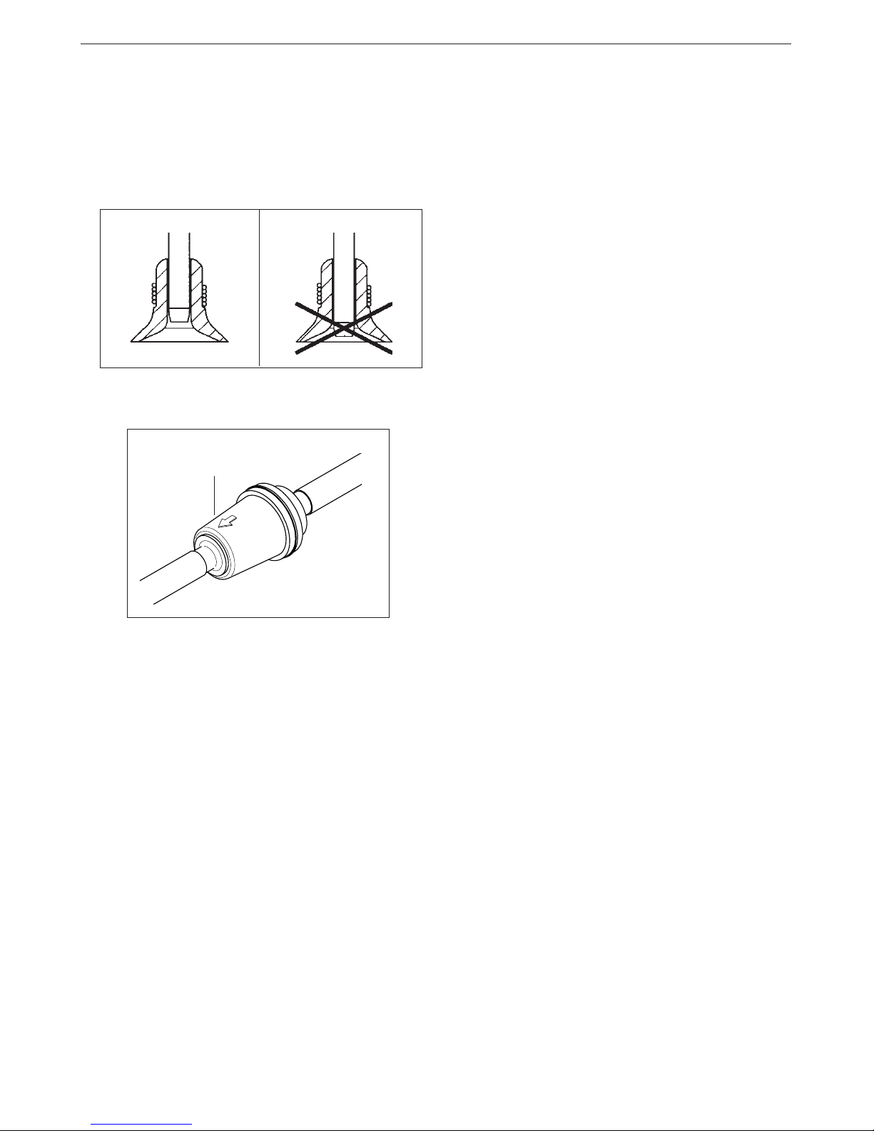
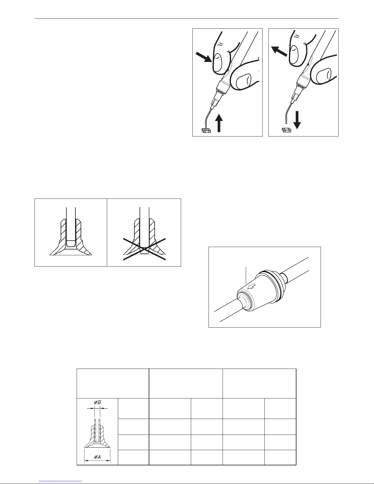
Detecting air leaks in the circuit
To detect air leaks in the circuit:
- Obstruct the tip inlet orifice
by pressing down on a
silicone disc, or bend the
tube connecting the
desoldering iron to the filter.
- Press the pushbutton vacuum pump.
If the red led lights up, there is no loss of
suction. Otherwise air gets into the system at
some point. This can occur at the desoldering
tip, or may be caused by the lid of the deposit,
lids of filters or because the air pump does not
function correctly due to dirty valves which
occurs when the air filter has not been used
correctly.
Changing the pump inlet filter
Verify the filter at the entrance of the pump, and
change it if dirty or obstructed, therefor:
Open the filter pulling the flap.
Take out the 2 cotton filters, throw away those
which are soiled and replace them with new
ones. Always use 2 filters.
Close the filter and check the airtightness.
Page 16
ENGLISH
15
PICK & PLACE PEN MP 2260
The pick & place pen MP 2260 ref. 2260000 for
the placing of SMD is also delivered with the AM
6000.
The pen is connected to the plug VACUUM of the
station. Please find the connection plan on page 1.
A set of straight and bent needles as well as a
set of different sized suction cups is delivered
with the station:
- Set of suction cups Ref. 0940163
- Set of straight needles Ref. 0901546
- Set of bent needles Ref. 0861660
The suction cups can be adjusted to the needles
in order to make the placement of SMD of different
sizes on boards easier.
These accessories allows the adjustment to weight
and size of any type of component.
Component pick-up (Fig. A)
Place the needle tip on the component and block
the control orifice with the first finger of the other
hand so that the component may be held to the
needle by suction.
Component placing (Fig. B)
Place the component in position on the printed
circuit. Remove your finger from the orifice
allowing air to enter whereby the component will
be released in the desired position.
Faults and remedies
We list below the most frequent faults and the
possible remedies which you yourself may be
able to apply. In any case, the JBC technical
assistance service will attend to you if required.
Insufficient suction
The tubes have to be checked for possible air
escapes and the correct connection of the tubes
to their terminals must be observed. Check the
incoming air filter in the interior of the station and
replace it if dirty or obstructed.
If in spite of this the suction is insufficient, the
self-contained vacuum pump should be checked.
Filter
Ref. 0861800
When you assemble the suction cup with the needle,
you should avoid the needle to stick out of the
lower part.
Fig. A
Fig. B
CUPS
Ref.: 0940163
STRAIGHT
NEEDLES
Ref.: 0901546
Ø A
mm
COLOR
2 x 4,3
BLACK
YELLOW2 x 7
PINK2 x 10
Ø B
mm
2 x 0,7
2 x 0,9
2 x 1,2
BENT
NEEDLES
Ref.: 0861660
COLOR
GREEN
YELLOW
PINK
Ø B
mm
2 x 0,8
2 x 0,9
2 x 1,2
Page 17
16
ENGLISH
ADVANCED HANDPIECES RANGE
All the Advanced soldering handpieces range can
be connected to the AM 6000 station.
The station AM 6000 includes the following products:
- Handpiece 2245 ref. 2245000 with the cartridge
2245-003 Ref. 2245003. Power: 50W. For general
soldering work.
- Soldering iron stand AD 8200 ref. 0268200.
- Set of accessories ref. 0780593 with cartridge
2245-007 Ref. 2245007. It can be chosen from a
wide range of different cartridges 2245 to adapt
perfectly to the needs of the job (pag. 126).
The following soldering handpieces can be
connected to the AM 6000 station:
- Handpiece 2010 ref. 2010000. Power: 20W. For
high precision work, SMD etc. Available
cartridges 2010: see page 127.
- Handpiece 2210 ref. 2210000. Power: 20W. For
high precision work, SMD etc. Available
cartridges 2210: see page 127.
- Handpiece 2045 ref. 2045000. Power: 50W. For
general soldering work. Available cartridges
2045: see page 126.
Two versions of soldering iron handpieces covered
with heat isolater are available:
- 2045 Thermo-isolated handpiece ref. 2045110.
- 2245 Thermo-isolated handpiece ref. 2245110.
These articles are not delivered with the station.
The handpieces and cartridges 2210 and 2245
comply with the MIL-SPEC-2000 referring to the
potential difference between the soldering tip and
ground connection, must be less than 2 mV.
For a soldering handpiece to work properly, the
following components are required: control unit,
soldering iron stand, one handpiece and one
cartridge.
The soldering iron is connected to the station in the
following way:
The cable connection of the soldering iron is
connected to the plug in the soldering iron stand
AD 8200 and the cable connection of the soldering
iron stand is plugged into the terminal SOLD of the
station. Please find the connection plan on figure.
Soldering iron stand
AD 8200
Ref.0268200
Handpiece 2010 Ref. 2010000
Handpiece 2210 Ref. 2210000
Handpiece 2045 Ref. 2045000
Handpiece 2245 Ref. 2245000
Cartridges 2045
Cartridges 2245
Cartridges 2010
Cartridges 2210
Soldering
connector
SOLD
Page 18
ENGLISH
17
Sleep function
One of the Series Advanced features is that when
the handpiece is placed in the holder, the
temperature at the tip drops automatically to the
sleep temperature. This function is only possible
because of the quick response time which does
not make the user realise the temperature rise to
reach the selected temperature. Also by this, the
oxidation of the tinning of the tip is considerably
reduced and tip life is extended.
To indicate that the soldering iron is in sleep-mode,
the green led starts pulsing. These parameters can
be modified using the Console AC 2600 Ref. 2600000.
In order to take advantage of the above
mentioned feature and as a security measure,
it is necessary to place the handpiece on stand
when the iron is not being used.
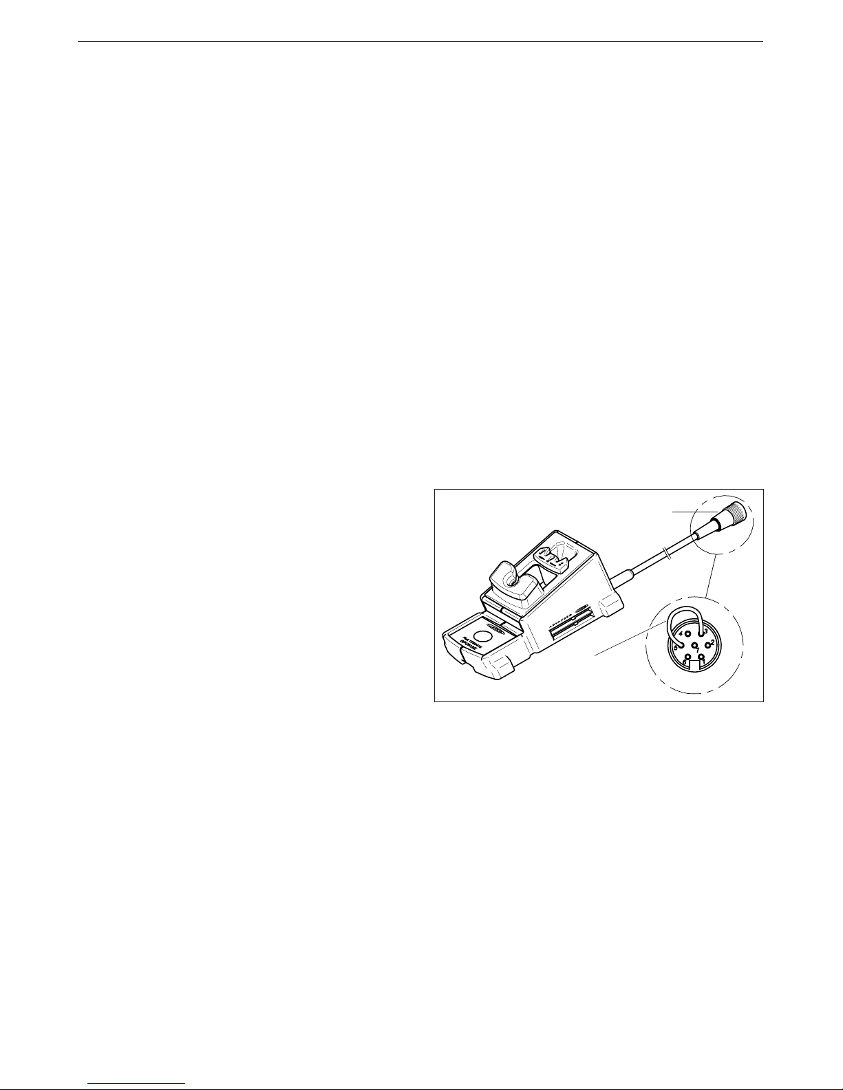
When connecting an old version solder stand, it may
happen that the sleep function does not work.
To resolve this problem, you should make a bridge
between pins number 3 and 5 from the aerial
connector of the cable of the stand, that plugs in
the station.
Aerial connector
Bridge between
pin number 3 & 5
OPERATION
LED lights
Red LED -ON- when lit, it indicates that the station is
plugged in the mains.
Green LED -READY- when lit, it indicates that the
system is ready and correctly set for working.
The green led light is on after a few seconds, is the
time needed to carry on the self-checking system.
The green light is pulsing when the soldering iron is
in sleep mode.
If the green led is not lit, the reason why, will be one
of the following:
1. The handpiece or the cartridge are not plugged
in.
2. The maximum available power has been
exceeded for too long - e.g. in a very thick
soldering at the high repetition rates.
3. The handpiece or cartridge has a short
circuit or an open circuit.
4. Any other trouble preventing the system from
working properly.
The green led goes off when the cartridge tip
touches the extractor and the station stops the
power supply.
The handpiece will reset itself automatically should
the cartridge short circuit or go open circuit.
Should the handpiece be subject to:
- An electrical surge or the cartridge has not been
fitted correctly.
Please turn the unit off and switch on again to
reset.
Only for users of AC 2600 console ref. 2600000.
If you lock the working temperature thanks to the
console, the green LED -READY- will remain on
while the dial is set at the locked temperature.
If the dial is not set at the locked temperature,
the green LED -READY- will be blinking. The
farther the dial will be set from the locked
temperature the slower the blinking pace will be.
Page 19
18
ENGLISH
Alignment
XX
XXXXX
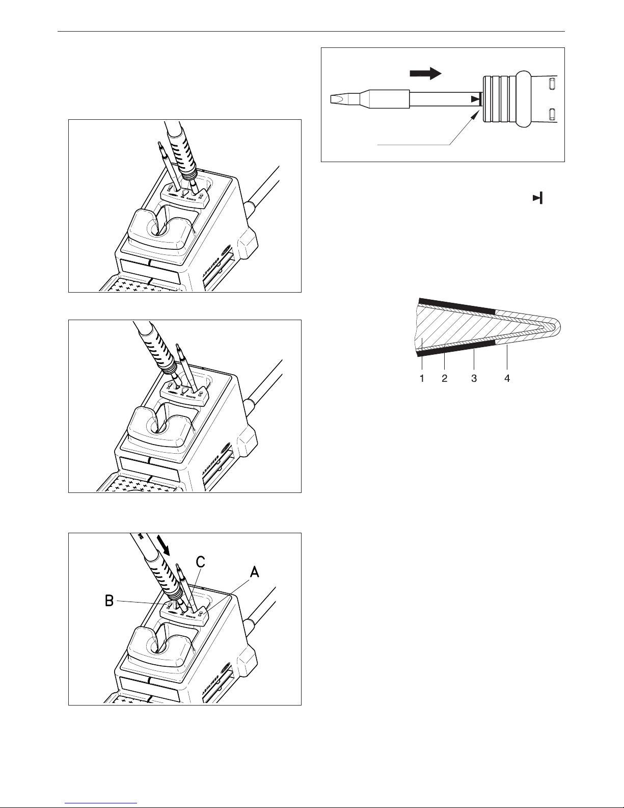
Important.
- It is essential to insert the cartridge till the end
for a good connection. Take the mark a s
reference.
Advanced series cartridge
Cartridge is made of the heating element which has the
heating system, temperature sensor and long life tip.
Long-life tip is basically made of:
1 Copper
2 Iron
3 Chromium
4 Tin plate
Long-life tip care
Except for the copper core, the rest of metals are
placed galvanically on layers relatively thin, so it
is necessary to avoid the reasons which can
cause its destruction.
To clean the tips, use the sponge included with
the stand and check it is slightly moisted.
Only deionised water (car battery water)
should be used in order to wet the sponge. If
normal water was to be used, it is very likely that
the tip will become dirty due to the salts dissolved
within the water.
To re-tin the soldering tips, we recommend using
the tip tinner/cleaner TT 9400 ref. 9400000.
2 - Place the handpiece on top of the new cartridge,
press it slightly down and remove the handpiece.
Changing the handpiece's cartridge
With the Advanced system, the cartridge can be
changed quickly, without turning off the station,
so you have two soldering irons in one. Here is
what to do to change the cartridge:
1 - Place the handpiece and remove the cartridge.
3 - Press the cartridge into the opening A, B or C:
A. For straight cartridges 2010 and 2210.
B. For curved cartridges 2010 and 2210.
C. For cartridges 2045 and 2245.
Page 20
ENGLISH
19
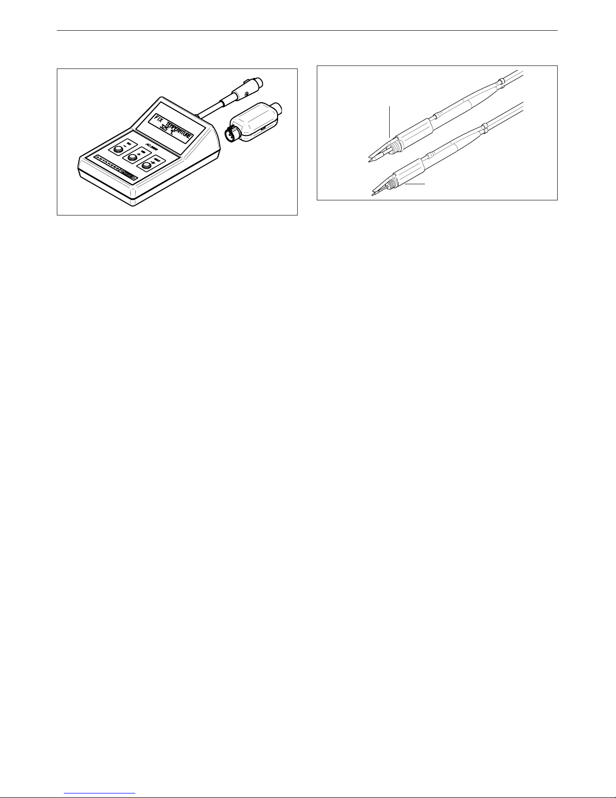
Console AC 2600
The console AC 2600 is designed for modifying the
original regulation program parameters of the following
Advanced control units:
- AD 2000 soldering station.
- AD 2200 soldering station.
- AD 4200 and AD 4300 dual soldering stations.
- AR 5500, AR 5800 (*) and DS 5300 (*) desoldering
stations.
- AM 6000 and AM 6500 (*) rework stations.
(*) These stations need a console whose
program version is 4.0 or higher.
Changes avalaible to perform:
- Fixing the the working temperature.
- Selection of temperature units in Celsius grades
-°C- or Fahrenheit -°F-.
- Modification of sleep temperatures and standby
times.
- Adjustment of temperature.
- Set the parameters back to the original parameters.
- Read-out data:
Working hours.
Sleep cycles and sleep hours.
Cartridge and iron changes.
Program version.
Fume extractor accessories
Specially designed for the Advanced Series
handpieces 2010/2210 and 2045/2245. Easily clips
onto the handpiece and can be quickly removed
for easy maintenance.
AC 2600
Ref. 2600000
For handpieces 2045/2245:
Standard Ref.0495000
+20mm longer Ref.0455002
For handpieces 2010/2210
Ref.0265000
Page 21
20
ENGLISH
HOT TWEEZERS
AM 6000 station allows to connect two different
models of tweezers, each one with its respective
range of cartridges and stand:
-Micro hot tweezers PA 1200 ref. 1200000.
- Hot tweezers PA 4200 ref. 4200000.
These articles are not delivered with the station.
For tweezers to work properly, the following
components are required: control unit, hot tweezers,
a stand and a set of cartridges corresponding to
the chosen tweezer.
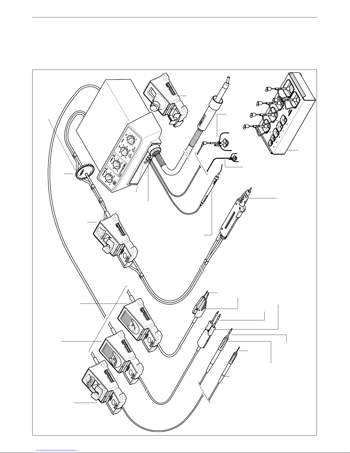
The tweezers are connected to the station in the
following way:
The cable connector of the tweezers is plugged
into the connector of the stand. The cable connector
of the stand is connected to the terminal of the
station. Please find the connection plan on figure.
Hot tweezers
PA 4200
Ref. 4200000
Cartridges for the hot
tweezers PA 4200
Stand PA 8120
Ref. 0748120
Cartridges 1200
Micro hot tweezers
PA 1200
Ref. 1200000
Stand PA 8110
Ref. 0748110
Soldering
connector
SOLD
Page 22

ENGLISH
21
OPERATION
LED lights
Red LED -ON- when lit, it indicates that the station is
plugged in the mains.
Green LED -READY- when lit, it indicates that the
system is ready and correctly set for working.
The green led light is on after a few seconds, is the
time needed to carry on the self-checking system.
The green light is pulsing when the hot tweezers are
in sleep mode.
If the green led is not lit, the reason why, will be one
of the following:
1. The hot tweezers or the cartridge are not
plugged in.
2. The maximum available power has been
exceeded for too long - e.g. in a very thick
soldering at the high repetition rates.
3. The hot tweezers or cartridge has a short circuit
or an open circuit.
4. Any other trouble preventing the system from
working properly.
The hot tweezers will reset itself automatically should
the cartridge short circuit or go open circuit.
Should the hot tweezers be subject to:
- An electrical surge or the cartridge has not been
fitted correctly.
Please turn the unit off and switch on again to reset.
Only for users of AC 2600 console ref. 2600000.
If you lock the working temperature thanks to the
console, the green LED -READY- will remain on
while the dial is set at the locked temperature.
If the dial is not set at the locked temperature,
the green LED -READY- will be blinking. The
farther the dial will be set from the locked
temperature the slower the blinking pace will be.
Sleep function
One of the Series Advanced features is that when
the hot tweezers are placed in the holder, the
temperature at the tip drops automatically to the
sleep temperature. This function is only possible
because of the quick response time which does
not make the user realise the temperature rise
to reach the selected temperature. Also by
this, the oxidation of the tinning of the tip is
considerably reduced and tip life is extended.
To indicate that the hot tweezers are in sleepmode, the green led starts pulsing. These
parameters can be modified using the Console
AC 2600 Ref. 2600000.
In order to take advantage of the above
mentioned feature and as a security measure,
it is necessary to place the hot tweezers on
stand when the iron is not being used.
Page 23
22
ENGLISH
Changing the cartridge
To extract the cartridge the screw needs to be
unfastened and the cartridge pulled out. Insert
the new cartridge and push it thoroughly. Then
check that both tips of the tweezers coincide
and screw it.
Important.
- It is essential to insert the cartridge till
the end for a good connection. Take the
mark as reference and check that both
parts of the tweezer coincide.
Alignment
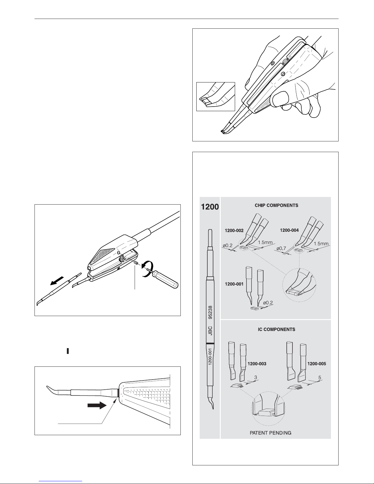
MICRO HOT TWEEZERS PA 1200
For micro hot tweezers to work properly, the
following components are required:
-Control unit.
-Micro hot tweezers PA 1200 ref. 1200000. For
general precision desoldering with SMD
components.
Power: 40W.
Effective power per cartridge fitted: 20W.
- Stand PA 8110 ref. 0748110.
-A set of cartridges (see range).
RANGE OF CARTRIDGES
PA 1200 has an individual temperature control
for each cartridge so it is supplied individually.
All the cartridges shown are actual size.
Screw
Ref. 0780841
Page 24
ENGLISH
23
JBC reserves the right to make technical changes without
prior notification.
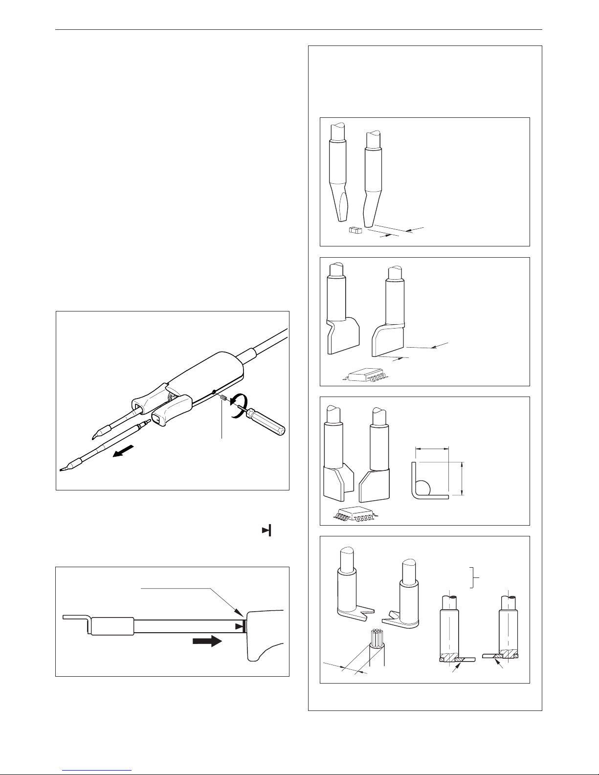
HOT TWEEZERS PA 4200
For hot tweezers to work properly, the following
components are required:
-Control unit.
-Hot tweezers PA 4200 ref. 4200000. For general
desoldering and soldering work in professional
electronics.
Power: 100W.
Effective power per cartridge fitted: 50W.
- Stand PA 8120 ref. 0748120.
-A set of cartridges (see range).
Changing the cartridge
To extract the cartridge the screw needs to be
unfastened and the cartridge pulled out. Insert
the new cartridge and push it thoroughly. Then
check that both tips of the tweezers coincide
and screw it.
Important.
- It is essential to insert the cartridge till the end
for a good connection. Take the mark as
reference and check that both parts of the
tweezer coincide.
Alignment
A
A
A
ØA
A
Ref. A mm
2245-271 1,5
2245-272 2,5
Chip components
Ref. A mm
2245-273 4,0
2245-274 6,0
2245-275 8,0
2245-276 10,0
2245-277 15,0
2245-278 20,0
Dual in line IC
Ref. A mm
2245-279 8,0
2245-280 11,0
QFP and PLCC
Ref. A mm
2245-281
2245-282
Cable stripper
RANGE OF CARTRIDGES
PA 4200 has an individual temperature contr ol
for each cartridge so it is supplied
individually.
2245-281
2245-282
3,5 max
PATENT PENDING
Screw
Ref. 0780841
Page 25
ESPAÑOL
25
Agradecemos la confianza depositada en JBC al adquirir esta estación. Ha sido
fabricada con las más estrictas normas de calidad para prestarle el mejor servicio.
Antes de poner en marcha el aparato, recomendamos leer con atención las
instrucciones que a continuación se detallan.
Soporte extractores
Ref.0932845
Tripode 20
Ref.0932050
Tripode 40
Ref.0932250
Soporte soldador
AD 8200
Ref.0268200
Desoldador DR 5600
Ref.5600000
* Lápiz 2210
Ref.2210000
* Cartuchos 2210
Cartuchos 2245
Pick & Place
MP 2260
Ref.2260000
Estación de reparación
multifunción AM 6000
Selector de aspiración del
Pick & Place y los extractores
Sop. calefactor JT 8700
Ref.0828700
Borne
equipotencial
* Estos elementos no se
suministran con la estación
Filtros de recambio
Ref.0781046
* Soporte pinza
PA 8120
Ref.0748120
* Soporte pinza
PA 8110
Ref.0748110
Lápiz 2245
Ref.2245000
* Pinza desoldadora
PA 4200
Ref.4200000
* Cartuchos para la pinza PA 4200
* Micro pinza desoldadora
PA 1200
Ref.1200000
* Cartuchos 1200
Soporte desoldador
DR 8500
Ref.0788500
Conjunto filtro aspiración
Ref.0821830
Page 26

ESPAÑOL
26
CARACTERISTICAS
La AM 6000 es una estación de reparación de
circuitos con componentes de inserción y SMD.
- AM 6000 230V Ref. 6000200
Está compuesta por 4 módulos que permiten
realizar las principales operaciones de reparación:
- Aire caliente para la desoldadura de
componentes SMD, de cualquier tamaño.
Utiliza el sistema exclusivo de JBC de
protectores-extractores y aire caliente pudiendo
realizar la desoldadura de una manera rápida y
limpia, concentrando el calor en el componente
a desoldar, protegiendo al mismo tiempo el
resto del circuito.
Se puede desoldar un integrado SMD de tamaño
medio en menos de 20 segundos.
- Desoldadura de componentes de inserción y
limpieza de pads en la desoldadura de SMT.
Para realizar esta función la estación dispone
del desoldador DR 5600, con bomba de
aspiración incorporada.
- Posicionador MP 2260 lápiz por aspiración
para la ayuda en la colocación de componentes.
- Soldadura de todo tipo de componentes, con
la rapidez de respuesta, potencia y recuperación
de temperatura de la serie Advanced. Puede
conectar los lápices Advanced 2010, 2210,
2045 o 2245 y las pinzas desoldadoras PA 1200
o PA 4200.
Composición de la estación
- Unidad de Control con calefactor 900 W
- Lápiz 2245 Ref. 2245000
con el cartucho 2245-003 Ref. 2245003
- Desoldador DR 5600 Ref. 5600000
con la punta 5600-003 Ref. 5600003
- Pick & Place MP 2260 Ref. 2260000
Accesorios para el calefactor:
- JT 8700 soporte calefactor Ref. 0828700
- Soporte extractores Ref. 0932845
- Conjunto de 5 protectores (Fig. 1, pág. 128)
- Conjunto de 5 extractores (Fig. 2, pág. 128)
-2 trípodes para los protectores (Fig. 1, pág. 128)
- Conjunto de ventosas JT Ref. 0930110
-3 Boquillas
Para facilitar la extracción de las boquillas el
soporte del calefactor dispone de un útil especial
(Fig. 3, pág. 128).
- Tubo aspiración con conectores Ref. 0932330
- Pedal con cable y conector Ref. 0964551
Accesorios para el lápiz:
- AD 8200 soporte soldador Ref. 0268200
Accesorios para el desoldador:
- DR 8500 soporte desoldador Ref. 0788500
- Conjunto filtro aspiración Ref. 0821830
- Filtros de recambio Ref. 0781046
- Conjunto de accesorios Ref. 0780593
Accesorios para el Pick & Place:
- Conjunto ventosas Pick & Place Ref. 0940163
- Conjunto agujas rectas Ref. 0901546
- Conjunto agujas dobladas Ref. 0861660
- Manual de instrucciones Ref. 0780448
La estación AM 6000 tiene los siguientes
accesorios, que no se incluyen con la estación:
- Lápiz 2010 Ref. 2010000
- Lápiz 2210 Ref. 2210000
- Lápiz 2045 Ref. 2045000
- Micro pinza desoldadora PA 1200 Ref. 1200000
- Pinza desoldadora PA 4200 Ref. 4200000
Page 27
ESPAÑOL
27
Datos técnicos de la Unidad de Control
- Potencia máxima soldador 50W.
- Potencia máxima desoldador 75W.
- Potencia calefactor 900W.
- Selección temperatura de soldadura:
100 a 371°C (±5%).
- Selección temperatura de desoldadura:
100 a 371°C (±5%).
- Selección temperatura del calefactor:
150 a 455°C (±5%).
- Regulación del caudal de aire de 6 a 45 l/min.
- Bomba de aspiración para la sujeción de los
CI.
- Potencia máxima de la estación: 1150W.
- Caja antiestática.
Resistencia típica superficial: 105-1011 Ohms/
cuadro.
- Cumple la normativa CE sobre seguridad
eléctrica, compatibilidad electromagnética y
protección antiestática.
- El borne equipotencial y la punta del soldador
están en conexión directa a la toma de tierra
de red.
- Peso del equipo completo: 17,6 kg.
- En el conector SOLD. sólo se pueden conectar
los lápices 2010, 2210, 2045 y 2245 y las pinzas
desoldadoras PA 1200 y PA 4200.
- En el conector DESOLD. sólo se puede conectar
el desoldador DR 5600.
FUNCIONAMIENTO
Descripción de los mandos
- PEDAL:
Activa la producción de aire caliente mientras
se mantiene accionado.
Cuando se deja de presionar, el sistema
desconecta el calefactor, pero la turbina
continua funcionando hasta que la temperatura
del aire es inferior a 100 °C.
- PULSADORES:
En cada pulsación, se activa o desactiva la
produción de aire caliente. Se para
automáticamente después de estar dos
minutos en marcha.
Cuando la luz roja del botón está encendida
indica que el calefactor está en marcha. Si
está parpadeando indica que hay un error.
A cada pulsación, se activa o desactiva la
bomba de aspiración.
Cuando la luz amarilla del botón está
encendida indica que la bomba de vacío está
en marcha.
- MANDOS:
TEMPERATURE
Permite seleccionar la temperatura entre
150 y 455°C para el calefactor. Las
temperaturas seleccionadas son valores de
referencia y su valor varía en función de la
distancia a la boquilla del calefactor.
Permite seleccionar la temperatura entre 100 y
371°C para las unidades de soldadura y
desoldadura.
AIR FLOW
Permite regular el caudal de aire en una escala
de 1 a 10, equivalente a un mínimo de 6 l/min,
y un máximo de 45 l/min.
- SELECTOR DE VACIO:
Dispone de dos tomas de aspiración, estando
activada la que coincida con la flecha.
HEAT
VACUUM
Medidas de seguridad
- El uso incorrecto de la herramienta puede ser
la causa de un incendio.
- Sea muy prudente cuando utilice la
herramienta en lugares donde hay materiales
inflamables.
- El calor puede producir la combustión de
materiales inflamables incluso cuando no
esten a la vista.
- No usar en la presencia de una atmósfera
explosiva.
- Coloque la herramienta en su soporte después
de usarla y dejela enfriar antes de
almacenarla.
Page 28
ESPAÑOL
28
PROCESO PARA DESOLDAR CON EL
CALEFACTOR
Recomendamos utilizar las boquillas de mayor
diámetro y reservar la mas pequeña (ø4mm) para
la desoldadura de pequeños componentes como
resistencias, condensadores, etc, téngase en
cuenta que con esta boquilla la concentración de
calor es mayor, por lo que para evitar quemar el
circuito impreso, aconsejamos no sobrepasar la
temperatura de 350 °C y el caudal de aire de 6.
Dependiendo del tamaño del circuito integrado a
desoldar, deberá utilizar:
A) Protector + trípode.
B)Extractor.
C) Trípode.
A) Protector + trípode:
- Seleccione el tamaño de protector y trípode en
función del IC a desoldar y colóquelo sobre el
componente.
- Ponga en marcha la bomba de aspiración
mediante el pulsador de VACUUM y coloque
el trípode. Presione la ventosa hasta que quede
adherida al componente.
- Mediante el pedal o el pulsador HEAT ponga
en marcha el generador de aire caliente,
dirigiéndolo con un movimiento circular a
los terminales del componente, procurando
repartir el calor de una forma homogénea.
- Cuando la soldadura pase al estado liquido, el
extractor levantará automáticamente el
componente.
B) Extractor:
- Seleccione el tamaño del extractor en función
del IC a desoldar. Ponga en marcha la bomba
de aspiración mediante el pulsador de
VACUUM.
Page 29
ESPAÑOL
29
- Coloque el extractor y presione la
ventosa hasta que quede adherida al
componente.
- Mediante el pedal o el pulsador HEAT ponga
en marcha el generador de aire caliente,
dirigiéndolo con un movimiento circular a los
terminales del componente, procurando repartir
el calor de una forma homogénea.
- Cuando la soldadura pase al estado liquido, el
extractor levantará automáticamente el
componente.
Existen como accesorio varios modelos de
protectores y extractores.
Las medidas de todos los protectores y
extractores se detallan en la página 128 del
manual.
C) Trípode:
Para los componentes pequeños y los que no se
puede utilizar extractor, recomendamos el uso
del trípode 20 Ref. 0932050 según la figura.
Use el trípode 40 Ref. 0932250 para integrados
de mayor tamaño.
PROCESO PARA SOLDAR
1 Una vez desoldado el componente, deberá
eliminar la soldadura que haya quedado en el
circuito impreso, usando nuestro desoldador
DR 5600 ref. 5600000.
Page 30

ESPAÑOL
30
2 Posicionar el componente o circuito integrado
con el Pick & Place MP 2260 ref. 2260000.
3 Una vez colocado el componente en su posición
correcta, suelde las patas. Si se trata de un
circuito integrado tipo "Flat Pack", suelde primero
una pata de cada ángulo del C I para fijarlo al
circuito.
4 Aplicar el Flux FL 9582 ref. 0046565 en los pads
y leads.
5Soldar las patas restantes. Para ello,
recomendamos utilizar nuestros soldadores
Advanced series, que disponen de
2 modelos de soldador:
Soldador 2210 ref. 2210000 para trabajos de
gran precisión, como soldadura SMD,etc.
Soldador 2245 ref. 2245000 para trabajos
generales de soldadura en electrónica
profesional.
Estos soldadores disponen de una amplia
gama de cartuchos con diferentes modelos de
puntas. Los cartuchos 2245-009 y 2245-010
están especialmente diseñados para soldar
circuitos SMD tipo QFP y PLCC.
Deberá utilizar hilo de estaño entre 0.5 - 0.7mm
de diámetro.
6 Dependiendo de las características del
componente utilice pasta de soldar y nuestra
estación de aire caliente TE 5000, que permite
una regulación muy fina del caudal de aire,
entre 4 y 11 l/min.
Page 31

ESPAÑOL
31
Cambio de la resistencia del calefactor.
1. Separe el muelle. Desenrosque los tornillos.
Siga el proceso inverso para volver a colocar el
calefactor.
Separe el muelle y la tapa. Estire del casquillo para
desconectar el calefactor de la estación.
2. Para sacar la resistencia, presione sobre una
superficie la parte inferior del mango.
MANTENIMIENTO
Cambio del calefactor.
Utilice una llave para desenroscar la tapa.
4. Coloque la nueva resistencia, presionando sobre
su extremo.
5. Enrosque los tornillos fuertemente para evitar
escapes de aire que pueden reducir la duración
de la resistencia. Por último ponga el muelle en
el extremo del mango.
3. Separe la resistencia del cable del calefactor.
Junta tórica ø17 x ø1,8
Page 32

ESPAÑOL
32
Filtro
Ref. 0861800
ANOMALIAS DE FUNCIONAMIENTO
La ventosa no queda adherida al componente.
Aspiración deficiente, Vacuum.
1 Compruebe que la ventosa este colocada
correctamente y en perfecto estado.
2 Compruebe el filtro de entrada de la bomba de
aspiración que hay en el interior de la estación
y cambielo si está sucio u obturado.
Posibles errores
El aparato se desconecta por completo cuando
aparece un error.
Esta es una lista de los errores más habituales:
- Falla la alimentación.
Compruebe si está fundido el fusible de
alimentación.
- La temperatura no aumenta.
Causas posibles:
· Resistencia calefactora abierta.
· Tensión de red baja, muy por debajo de la
nominal.
- No hay lectura del termopar.
Causas posibles: termopar abierto.
- Caudal de aire insuficiente, lo que ha provocado
una subida excesiva de la temperatura del
calefactor.
Antes de recuperar este tipo de error, deberá
esperar a que la temperatura descienda.
Causas posibles: conductos de aire rotos u
obstruidos o bomba de aire estropeada.
- Error en lecturas del cuenta vueltas de la bomba
de aire.
Causas posibles: bomba de aire estropeada o
funcionamiento defectuoso del circuito sensor
óptico.
Para recuperar cualquiera de los errores
anteriores es necesario accionar el interruptor
general situado en la parte posterior de la
estación; en este momento el pedal no puede
estar apretado.
Page 33

ESPAÑOL
33
DESOLDADOR DR 5600
La estación AM 6000 se suministra con:
- El desoldador DR 5600 ref. 5600000 con la punta
5600-003 ref. 5600003.
Potencia desoldador: 75W.
- El soporte desoldador DR 8500 ref. 0788500.
- El conjunto filtro aspiración ref. 0821830.
- El conjunto de accesorios ref. 0780593 que
incluye, las puntas del desoldador: 5600-003,
5600-004 y 5600-005.
El desoldador se conecta a la estación de la
siguiente forma:
El cable del desoldador se debe conectar al soporte
desoldador DR 8500 y el tubo de aspiración al
CONJUNTO FILTRO ASPIRACION y este a la toma
de aspiración SUCTION de la estación. El cable del
soporte desoldador se conecta al conector DESOLD
de la estación. Muy importante, es indispensable
intercalar el CONJUNTO FILTRO ASPIRACION de lo
contrario se inutilizará la bomba de aspiración.
Soporte desoldador
DR 8500
Ref.0788500
Desoldador DR 5600
Ref.5600000
Filtros de recambio
Ref.0781046
Cartucho desoldador
Ref.5600010
Toma de aspiración
SUCTION
Conector
desoldador
DESOLD
Conjunto filtro aspiración
Ref.0821830
Page 34

ESPAÑOL
34
FUNCIONAMIENTO
Luces de señalización
Luz roja -ON- encendida indica que la estación está
conectada a tensión de red.
Luz verde -READY- encendida indica que el
sistema está dispuesto y en correctas condiciones
de trabajo.
La luz verde se enciende después de unos pocos
segundos, que es el tiempo necesario para que se
realice el autochecking del sistema.
La luz verde parpadea cuando el desoldador está en
reposo.
Si la luz verde está apagada, será debido a alguno
de los siguientes motivos:
1. Que el desoldador no está conectado.
2. Que se ha superado la potencia máxima disponible
durante un tiempo excesivo, por ejemplo
desoldaduras muy gruesas y repetidas, etc.
3. Que la resistencia desoldadora está en
cortocircuito o circuito abierto.
4. Cualquier otra anomalía que haga funcionar
defectuosamente el sistema.
El reset de errores es automático cuando el desoldador
o el cartucho están en cortocircuito o circuito abierto.
El reset de errores no es automático ,se debe apagar
y volver a conectar la estación, cuando:
- Existe un error de exceso de aporte de energía.
Cuando se aprieta el pulsador del desoldador se
encenderá una de las dos luces que hay en SUCTION:
Luz verde -SUCTION- si se enciende esta luz
indica que el desoldador está dispuesto y en
correctas condiciones de trabajo.
Luz roja -SUCTION- si se enciende esta luz indica
que está obstruido el circuito de vacío.
Desoldador en reposo
Una de las cualidades de la serie Advanced,
es que cuando el desoldador se coloca en el
soporte, la temperatura baja automáticamente
hasta la temperatura de reposo. Esto es
posible, gracias a la rapidez de su respuesta
térmica, que permite pasar de la temperatura
de reposo a la de trabajo sin interrupción. Con
lo cual se consigue una gran reducción en la
oxidación del estañado y aumenta de una forma
muy importante la duración de la punta.
Para indicar que el desoldador está en reposo,
la luz verde de la unidad de control se pone a
parpadear. Estos parámetros se pueden
modificar con la Consola AC 2600 Ref.
2600000.
Para beneficiarse de la cualidad anterior y como
medida de seguridad, es necesario colocar el
desoldador en el soporte cuando no se utilice.
DR 5600 Ref.5600000
Punta desoldador
Cartucho
Pulsador aspiración
Tubo aspiración
Cable desoldador
Depósito estaño
Metal
Vidrio
Esto será debido a alguna de las siguientes
causas:
- La punta de desoldador está embozada.
- El depósito de estaño está lleno.
- El filtro del desoldador está sucio.
- El filtro de la toma de aspiración de la estación
está sucio.
Sólo para usuarios de la cónsola AC 2600 ref.
2600000.
Si se fija la temperatura con la consola, el led verde
READY sólo permanece encendido contínuamente
cuando el dial señalice la temperatura fijada.
Si el dial no está posicionado en la temperatura
fijada, el led verde READY parpadeará a una
velocidad más lenta cuanto más lejos de la
temperatura fijada se encuentre.
Page 35

ESPAÑOL
35
RECOMENDACIONES DE USO
Para soldar y desoldar
- Los componentes y el circuito deben estar
limpios y desengrasados.
- Con preferencia seleccione una temperatura
inferior a 350°C. El exceso de temperatura
puede provocar el desprendimiento de las
pistas del circuito impreso.
- La punta debe estar bien estañada para
conducir bien el calor. Si permanece mucho
tiempo en reposo, estáñela de nuevo.
Proceso para desoldar
Utilice un modelo de punta de mayor diámetro
interior que el pin a desoldar, con el fin de
conseguir el máximo de aspiración y de
transmisión térmica, asegurese de que la punta
está bien estañada.
1 Apoye la punta del desoldador, de forma
que el terminal del componente penetre dentro
del orificio de la punta.
2 Cuando la soldadura se licúe, imprima a la
punta del desoldador un movimiento de
rotación que permita desprender de los
laterales el terminal del componente.
3 Accione entonces, no antes, el pulsador de
la bomba de vacío el tiempo necesario para
succionar la soldadura.
1
2
3
Después de cada pulsación del botón del
desoldador hay un breve retardo hasta el paro
de la bomba de aspiración, con la finalidad de
asegurar que se vacía completamente el circuito
de aspiración.
Si algún terminal ha quedado con restos de
soldadura, después de intentar desoldarlo,
suéldelo nuevamente aportando estaño y repita
la operación de desoldar.
Ref. 5600-001 5600-002 5600-003 5600-004 5600-005 5600-006 5600-007
5600
A ø (mm)
B ø (mm)
max. pin ø
(mm)
001 / 011
1.4
0.6
0.4
002 / 012
1.8
0.8
0.6
003 / 013
2.7
1
0.8
004
3.2
1.3
1.1
005
3.4
1.6
1.4
006
4.2
2
1.7
007
4.8
2.5
2.3
A ø
B ø
5600-012 5600-0135600-011
PUNTAS DESOLDADOR
Estas puntas están
especialmente
deseñadas para la
limpieza de pads.
Page 36

ESPAÑOL
36
- Para la limpieza de las puntas utilice la
esponja del soporte, que debe estar húmeda
pero no empapada de agua.
Es necesario utilizar sólo agua
desionizada para humedecer la esponja.
Si utiliza agua normal es muy probable que
la punta se ensucie con las sales disueltas
que hay en el agua.
- No lime ni utilice herramientas abrasivas que
puedan destruir la capa de protección
superficial de la punta y evite los golpes.
- Si la punta ha estado mucho tiempo sin
ser estañada, utilice un cepillo metálico para
eliminar el óxido y la suciedad.
Cambio de la punta del desoldador
Esta operación debe realizarse en caliente a una
temperatura mínima de 250°C, para que los
residuos de estaño que hayan quedado en el
interior estén fundidos.
- Desenrosque la punta a sustituir, con la ayuda
de la llave que se suministra.
- Coloque la nueva punta. Apriete con la llave
para conseguir una buena estanqueidad.
Conservación de las puntas
- Periódicamente se debe pasar la baqueta del
diámetro mayor que permita en el interior de la
punta, para limpiar el conducto de aspiración.
Vaciado depósito del desoldador y cambio del
filtro
Para realizar esta operación debe desenroscar el
tapón y retirar el depósito, seguidamente
extraemos el filtro y la espiral y con una baqueta
limpiaremos el interior del depósito.
- Observe el estado del filtro y cámbielo si
estuviera sucio o degradado.
- Vuelva a poner el depósito con el filtro y la
espiral. Cierre el conjunto enroscando el
tapón.
Tipos de deposito de estaño
Se puede escoger entre dos tipos de depósitos:
- Metálico Ref. 0812630.
- Vidrio Ref. 0812620.
Ref. 0780550
Tapón depósito
Baqueta
Ref. 0786640
Filtro Ref.0780840
Depósito
Espiral
IMPORTANTE: NO hacer funcionar la bomba de
vacío durante la operación de estañado de la
punta del desoldador, ya que el humo que
desprende el flux ensuciará rápidamente los
conductos y el filtro de entrada de la bomba.
Page 37

ESPAÑOL
37
- Enrosque los tornillos de la tapa. Coloque
de nuevo la espiral y el filtro en el
depósito. Ponga el depósito dentro del
desoldador y finalmente enrosque el tapón
del depósito.
Cartucho
Ref. 5600010
Tapón depósito
Baqueta
Ref. 0786640
Filtro Ref.0780840
Depósito
Espiral
Cambio del cartucho del desoldador (Ref.
5600010)
- Para realizar está operación debe
desenroscar el tapón y retirar el depósito,
seguidamente extraiga el filtro y la espiral
y con una baqueta limpie el interior del
depósito.
- Desenrosque los tres tornillos de fijación
de la tapa del desoldador. Levante la tapa
y retire el cartucho.
- Coloque el nuevo cartucho. Compruebe
que el extremo del tubo se sitúa en la
ranura del mango (ver figura).
Page 38

ESPAÑOL
38
Limpieza de la válvula interna de la bomba de
vacío
Debe abrir la unidad de control, para ello:
- Desconecte la estación de la red eléctrica.
- Invierta la unidad, quite los tornillos
de fijación.
- Ponga la estación en posición normal y
levante la tapa superior.
- Desenrosque los cuatro tornillos que sujetan
la tapa de la bomba.
- Limpie la válvula con un paño mojado
en alcohol. Si estuviera excesivamente
impregnada, cámbiela por una nueva.
Ref. 0982970.
Detección de perdidas de aspiración.
Para detectar pérdidas de aspiración en el circuito:
- Obstruya el orificio de entrada
de la punta, presionando
sobre un disco de silicona, o
estrangule el tubo que va
del desoldador al filtro.
- Pulse el botón de puesta en marcha de la
bomba de vacío.
El indicador del led rojo de SUCTION deberá
encenderse, esto significa que no habrá perdida
de vacío. Si no es así, significa que hay una
entrada de aire por cualquiera de las juntas,
como pueden ser la punta del desoldador, el
tapón de cierre del depósito, los tapones del
filtro de entrada de la bomba, o bien la bomba no
aspira suficiente por estar sucia la válvula interna
motivado por haber trabajado sin el conjunto filtro
aspiración o sin filtros.
Cambio del filtro de entrada de la bomba
Compruebe el filtro de entrada de la bomba y
cambielo si está sucio u obturado, para ello:
- Abra el filtro tirando de las lengüetas.
- Extraiga los 2 filtros de algodón, deseche los
que estuvieran sucios y coloque unos nuevos
en su lugar. Use siempre 2 filtros.
Cierre el filtro y verifique que no hayan perdidas
de aspiración.
Page 39

ESPAÑOL
39
LAPIZ POSICIONADOR MP 2260
La estación AM 6000 se suministra con el lápiz
Pick & Place MP 2260 ref. 2260000 que es un
posicionador de componentes de montaje
superficial SMD.
El lápiz se debe conectar al conector de VACUUM
de la estación. Vea el gráfico de conexionado de
la estación en la pag. 25.
Se entrega un juego de agujas rectas, un juego
de agujas dobladas y un juego de ventosas de
diferentes diámetros:
- Juego de ventosas Ref. 0940163
- Juego de agujas rectas Ref. 0901546
- Juego de agujas dobladas Ref. 0861660
Las ventosas son adaptables a las agujas para
facilitar la colocación de componentes SMD de
distintos tamaños sobre circuitos impresos.
Estos accesorios le permitirán adaptarse al peso
y tamaño de cualquier componente.
Recoger un componente (Fig. A)
Coloque la punta de la aguja sobre el componente y
obture con el dedo el orificio del lápiz para que por
aspiración, el componente quede sujeto a la aguja.
Posicionar un componente (Fig. B)
Deposite el componente en su posición del circuito
impreso. Retire el dedo del orificio dejando libre
la entrada de aire con lo que el componente
quedará suelto y en la posición deseada.
Anomalías y solución
Le relacionamos las anomalías mas frecuentes y
su posible solución, que posiblemente podrá Vd.
mismo reparar. En cualquier caso, el servicio de
asistencia técnica JBC le atenderá en lo que
precise.
No hay suficiente aspiración
Verifique que no hay fugas y que todos los tubos
estén bien introducidos en sus alojamientos.
Compruebe el filtro de entrada de la bomba de
aspiración que hay en el interior de la estación y
cambielo si está sucio u obturado.
Si a pesar de ello la aspiración es insuficiente se
debe revisar la bomba de vacío.
Filtro
Ref. 0861800
Al montar la ventosa en la aguja, evitar que ésta
salga por la parte inferior.
Fig. A
Fig. B
VENTOSAS
Ref.: 0940163
AGUJAS
RECTAS
Ref.: 0901546
Ø A
mm
COLOR
2 x 4,3
NEGRO
AMARILLO
2 x 7
ROSA2 x 10
Ø B
mm
2 x 0,7
2 x 0,9
2 x 1,2
AGUJAS
DOBLADAS
Ref.: 0861660
COLOR
VERDE
AMARILLO
ROSA
Ø B
mm
2 x 0,8
2 x 0,9
2 x 1,2
Page 40

ESPAÑOL
40
LAPICES SOLDADORES ADVANCED
La estación AM 6000 permite conectar todos los
lápices soldadores de la gama Advanced.
La estación AM 6000 se suministra con:
- El lápiz 2245 ref. 2245000 con el cartucho 2245-
003 ref. 2245003. Potencia: 50W. Se utiliza en
trabajos de soldadura en electrónica general.
- El soporte soldador AD 8200 ref. 0268200.
- El conjunto de accesorios ref. 0780593 que
incluye, el cartucho 2245-007 Ref. 2245007. Existe
una amplia gama de cartuchos 2245 para que
pueda escoger el más adecuado al trabajo a
realizar (pag. 126).
La estación AM 6000 también permite conectar:
- El lápiz 2010 ref. 2010000. Potencia: 20W. Se
utiliza para trabajos de precisión, SMD, etc. Vea
la gama de cartuchos 2010 en la pag. 127.
- El lápiz 2210 ref. 2210000. Potencia: 20W. Se
utiliza para trabajos de precisión, SMD, etc. Vea
la gama de cartuchos 2210 en la pag. 127.
- El lápiz 2045 ref. 2045000. Potencia: 50W. Se
utiliza en trabajos de soldadura en electrónica
general. Vea la gama de cartuchos 2045 en la
pag. 126.
Existe una versión de los lápices 2045 y 2245 con
mangos cubiertos de un aislante térmico.
- Lápiz 2045 termo-aislado ref. 2045110.
- Lápiz 2245 termo-aislado ref. 2245110.
Estos productos están disponibles como un
accesorio, no se incluyen en la estación.
Los lápices y cartuchos 2210 y 2245 cumplen las
especificaciones MIL-SPEC-2000 en cuanto a
diferencia de potencial entre la punta del soldador
y la toma de tierra, que debe ser menor de 2mV.
Para tener el soldador operativo se necesita: la
unidad de control, el soporte soldador, un lápiz y
un cartucho.
El lápiz se conecta a la estación de la siguiente
forma:
El cable del lápiz se debe conectar al conector que
existe en el soporte soldador AD 8200 y el cable del
soporte soldador se conecta en el conector SOLD
de la estación. Vea el gráfico de conexionado en la
figura.
Soporte soldador
AD 8200
Ref.0268200
Lápiz 2010 Ref. 2010000
Lápiz 2210 Ref. 2210000
Lápiz 2045 Ref. 2045000
Lápiz 2245 Ref. 2245000
Cartuchos 2045
Cartuchos 2245
Cartuchos 2010
Cartuchos 2210
Conector
soldador
SOLD
Page 41

ESPAÑOL
41
Soldador en reposo
Una de las cualidades de la serie Advanced, es que
cuando el lápiz se coloca en el soporte, la temperatura
baja automáticamente hasta la temperatura de
reposo. Esto es posible, gracias a la rapidez de su
respuesta térmica, que permite pasar de la
temperatura de reposo a la de trabajo sin interrupción.
Con lo cual se consigue una gran reducción en la
oxidación del estañado y aumenta de una forma
muy importante la duración de la punta.
Para indicar que el soldador está en reposo, la luz
verde de la unidad de control se pone a parpadear.
Estos parámetros se pueden modificar con la
Consola AC 2600 Ref. 2600000.
Para beneficiarse de la cualidad anterior y como
medida de seguridad, es necesario colocar el
lápiz en el soporte cuando no se utilice.
Si se conecta un soporte para soldador que
corresponda a versiones anteriores, puede suceder
que no funcione la función reposo.
Para solucionarlo deberá hacer un puente entre los
terminales 3 y 5 del conector aereo del cable del
soporte que se conecta a la estación.
Conector aereo
Puente entre los
terminales 3 y 5
FUNCIONAMIENTO
Luces de señalización
Luz roja -ON- encendida indica que la estación está
conectada a tensión de red.
Luz verde -READY- encendida indica que el
sistema está dispuesto y en correctas condiciones
de trabajo.
La luz verde se enciende después de unos pocos
segundos, que es el tiempo necesario para que se
realice el autochecking del sistema.
La luz verde parpadea cuando el soldador está en
reposo.
Si la luz verde está apagada, será debido a alguno de
los siguientes motivos:
1. Que el lápiz con cartucho no está conectado.
2. Que se ha superado la potencia máxima disponible
durante un tiempo excesivo, por ejemplo
soldaduras muy gruesas y repetidas, etc.
3. Que el lápiz con cartucho está en cortocircuito
o circuito abierto.
4. Cualquier otra anomalía que haga funcionar
defectuosamente el sistema.
La luz verde se apaga y el soldador deja de ser
alimentado mientras esté en contacto con el
extractor de cartuchos. Esto sucede cuando el
soldador lleva tres segundos en contacto con el
extractor.
El reset de errores es automático cuando el lápiz o el
cartucho están en cortocircuito o circuito abierto.
El reset de errores no es automático, se debe apagar
y volver a conectar la estación, cuando:
- Existe un error de exceso de aporte de energía.
Sólo para usuarios de la cónsola AC 2600 ref.
2600000.
Si se fija la temperatura con la consola, el led verde
READY sólo permanece encendido contínuamente
cuando el dial señalice la temperatura fijada.
Si el dial no está posicionado en la temperatura
fijada, el led verde READY parpadeará a una
velocidad más lenta cuanto más lejos de la
temperatura fijada se encuentre.
Page 42

ESPAÑOL
42
Importante.
- Es indispensable introducir el cartucho hasta
el fondo, para conseguir una buena conexion.
Utilice la marca como referencia.
Alineación
XX
XXXXX
Cartuchos de la serie Advanced
El cartucho está compuesto por el elemento calefactor
que incorpora el sistema de calentamiento y el sensor
de la temperatura y también la punta de larga duración.
La punta de larga duración está compuesta
básicamente por:
1 Cobre
2 Hierro
3 Cromo
4 Estaño
Conservación de las puntas de larga duración
Salvo el núcleo que es de cobre el resto de
metales está depositado galvánicamente en
capas relativamente finas por lo cual es necesario
evitar las causas que puedan provocar su
destrucción.
Para la limpieza de las puntas utilice la esponja
del soporte, que debe estar húmeda pero no
empapada de agua.
Es necesario utilizar sólo agua desionizada
para humedecer la esponja. Si utiliza agua
normal es muy probable que la punta se ensucie
con las sales disueltas que hay en el agua.
Si la punta está muy oxidada recomendamos
utilizar la pasta restañadora de puntas TT 9400
ref. 9400000.
2 - Sitúe el lápiz sobre el cartucho a cambiar,
presione ligeramente y retírelo.
Cambio del cartucho del lápiz
El sistema Advanced permite el cambio rápido
del cartucho, sin parar la estación, con lo que
dispondrá de dos soldadores en uno. Para ello
siga el proceso que se indica a continuación.
1 - Coloque el lápiz y extraiga el cartucho.
3 - Presione a fondo el lápiz sobre el orificio A, B
o C:
A. Para cartuchos 2010 y 2210 rectos.
B. Para cartuchos 2010 y 2210 curvados.
C. Para cartuchos 2045 y 2245.
Page 43

ESPAÑOL
43
Consola AC 2600
La consola AC 2600 está diseñada para modificar
los parámetros originales del programa de regulación
de las siguienes estaciones de la gama Advanced:
- Estación soldadora AD 2000.
- Estación soldadora AD 2200.
- Estaciones soldadoras dual AD 4200 y AD 4300.
- Estaciones desoldadoras AR 5500, AR 5800 (*) y
DS 5300 (*).
- Estaciones de reparación multifunción AM 6000 y
AM 6500 (*).
(*) En estas estaciones es necesario disponer de
una consola con la versión de programa 4.0 o
superior.
Permite:
- Fijar la temperatura.
- Selección de las unidades de temperatura en
grados Celsius -°C- o Fahrenheit -°F-.
- Cambiar la temperatura y el tiempo de sleep.
- Ajustar la temperatura.
- Cambiar los parámetros de la estación a los
preseleccionados en fábrica.
- Leer los contadores de:
Horas de trabajo.
Ciclos y horas de sleep.
Cambios de cartucho.
Versión del programa.
AC 2600
Ref. 2600000
Accesorio aspira-humos
Para los lápices 2010/2210 y 2045/2245. Sujección
por sistema clip, se sustituyen con rapidez para
su mantenimiento.
Para los lápices 2045/2245:
Standard Ref.0495000
20mm más largo Ref.0455002
Para los lápices
2010/2210
Ref.0265000
Page 44

ESPAÑOL
44
PINZAS DESOLDADORAS
La estación AM 6000 permite conectar dos
modelos de pinza desoldadora, con sus
respectivas gamas de cartuchos y soporte:
-La micro pinza desoldadora PA 1200 ref.
1200000.
-La pinza desoldadora PA 4200 ref. 4200000.
Estos productos están disponibles como un
accesorio, no se incluyen en la estación.
Para tener una pinza desoldadora operativa se
necesita: la unidad de control, una pinza, el
soporte y un par de cartuchos correspondientes
a la pinza que se haya escogido.
La pinza se conecta a la estación de la siguiente
forma:
El cable de la pinza se debe conectar al conector
que existe en el soporte y el cable del soporte
pinza se conecta en el conector SOLD de la
estación. Vea el gráfico de conexionado en la
figura.
Pinza desoldadora
PA 4200
Ref. 4200000
Cartuchos para la pinza
PA 4200
Soporte pinza desoldadora
PA 8120
Ref. 0748120
Cartuchos 1200
Micro pinza desoldadora
PA 1200
Ref. 1200000
Soporte pinza desoldadora
PA 8110
Ref. 0748110
Conector
soldador
SOLD
Page 45

ESPAÑOL
45
FUNCIONAMIENTO
Luces de señalización
Luz roja -ON- encendida indica que la estación está
conectada a tensión de red.
Luz verde -READY- encendida indica que el
sistema está dispuesto y en correctas condiciones
de trabajo.
La luz verde se enciende después de unos pocos
segundos, que es el tiempo necesario para que se
realice el autochecking del sistema.
La luz verde parpadea cuando la pinza está en
reposo.
Si la luz verde está apagada, será debido a alguno de
los siguientes motivos:
1. Que la pinza desoldadora con cartucho no está
conectada.
2. Que se ha superado la potencia máxima disponible
durante un tiempo excesivo, por ejemplo
soldaduras muy gruesas y repetidas, etc.
3. Que la pinza desoldadora con cartucho está
en cortocircuito o circuito abierto.
4. Cualquier otra anomalía que haga funcionar
defectuosamente el sistema.
El reset de errores es automático cuando la pinza
desoldadora o el cartucho están en cortocircuito o
circuito abierto.
El reset de errores no es automático, se debe apagar
y volver a conectar la estación, cuando:
- Existe un error de exceso de aporte de energía.
Sólo para usuarios de la cónsola AC 2600 ref.
2600000.
Si se fija la temperatura con la consola, el led verde
READY sólo permanece encendido contínuamente
cuando el dial señalice la temperatura fijada.
Si el dial no está posicionado en la temperatura
fijada, el led verde READY parpadeará a una
velocidad más lenta cuanto más lejos de la
temperatura fijada se encuentre.
Pinza desoldadora en reposo
Una de las cualidades de la serie Advanced, es
que cuando la pinza desoldadora se coloca en el
soporte, la temperatura baja automáticamente hasta
la temperatura de reposo. Esto es posible, gracias
a la rapidez de su respuesta térmica, que permite
pasar de la temperatura de reposo a la de trabajo
sin interrupción. Con lo cual se consigue una gran
reducción en la oxidación del estañado y aumenta
de una forma muy importante la duración de la
punta.
Para indicar que la pinza desoldadora está en
reposo, la luz verde de la unidad de control se
pone a parpadear. Estos parámetros se pueden
modificar con la Consola AC 2600 Ref.
2600000.
Para beneficiarse de la cualidad anterior y como
medida de seguridad, es necesario colocar la
pinza desoldadora en el soporte cuando no se
utilice.
Page 46

ESPAÑOL
46
Cambio del cartucho
Afloje el tornillo de sujección y extraiga el
cartucho. Coloque el nuevo cartucho, presione
a fondo comprobando que coincidan las dos
puntas de la pinza. Apriete de nuevo el tornillo.
Importante.
- Es indispensable introducir el cartucho hasta
el fondo, para conseguir una buena conexión.
Utilice la marca como referencia y
compruebe que coincidan las puntas de la
pinza.
Alineación
MICRO PINZA DESOLDADORA PA 1200
Para tener la micro pinza operativa se necesita:
-La unidad de control.
-La micro pinza desoldadora PA 1200 ref.
1200000. Se utiliza para desoldaduras de
precisión con componentes SMD.
Potencia: 40W.
Potencia efectiva del cartucho: 20W.
- El soporte pinza PA 8110 ref. 0748110.
- Un par de cartuchos de la gama de cartuchos
para la micro pinza PA 1200.
GAMA DE CARTUCHOS
La pinza PA 1200 dispone de un control de
temperatura independiente para cada
cartucho, por ello se suministran
individualmente.
Todos los cartuchos son a tamaño real.
Tornillo
Ref. 0780841
Page 47

ESPAÑOL
47
PINZA DESOLDADORA PA 4200
Para tener la pinza operativa se necesita:
-La unidad de control.
-La pinza desoldadora PA 4200 ref. 4200000.
Se utiliza para trabajos generales de
desoldadura y soldadura en electrónica
profesional.
Potencia: 100W.
Potencia efectiva del cartucho: 50W.
- El soporte pinza PA 8120 ref. 0748120.
- Un par de cartuchos de la gama de cartuchos
para la pinza PA 4200.
Cambio del cartucho
Afloje el tornillo de sujección y extraiga el
cartucho. Coloque el nuevo cartucho, presione
a fondo comprobando que coincidan las dos
puntas de la pinza. Apriete de nuevo el tornillo.
Importante.
- Es indispensable introducir el cartucho hasta
el fondo, para conseguir una buena conexión.
Utilice la marca como referencia y
compruebe que coincidan las puntas de la
pinza.
Alineación
JBC se reserva el derecho de introducir modificaciones
sin previo aviso
A
A
A
ØA
A
Ref. A mm
2245-271 1,5
2245-272 2,5
Componentes chips
Ref. A mm
2245-273 4,0
2245-274 6,0
2245-275 8,0
2245-276 10,0
2245-277 15,0
2245-278 20,0
Dual in line IC
Ref. A mm
2245-279 8,0
2245-280 11,0
QFP y PLCC
Ref. A mm
2245-281
2245-282
Pela cables
GAMA DE CARTUCHOS
La pinza PA 4200 dispone de un control de
temperatura independiente para cada
cartucho, por ello se suministran
individualmente.
2245-281
2245-282
3,5 max
PATENT PENDING
Tornillo
Ref. 0780841
Page 48

FRANÇAIS
49
Nous vous remercions de la confiance déposée en JBC à travers l’acquisition de
cette station. Elle est fabriquée dans les plus strictes normes de qualité pour vous
rendre un meilleur service. Avant de mettre l’appareil en marche, nous vous
recommandons de lire attentivement les instructions détaillées ci-après.
Support extracteurs
Réf.0932845
Trépied 20
Réf.0932050
Trépied 40
Réf.0932250
Support fer à souder
AD 8200
Réf.0268200
Fer à dessouder DR 5600
Réf.5600000
* Crayon 2210
Réf.2210000
* Cartouches 2210
Cartouches 2245
Crayon
positionneur
MP 2260
Réf.2260000
Station de réparation
multifonction AM 6000
Sélecteur d’aspiration du crayon
pick & place et des extracteurs
Sop. calefactor JT 8700
Ref.0828700
Connecteur
équipotentiel
* Ces éléments ne sont pas
livrés avec la station
Filtres de rechange
Réf.0781046
* Support pince à
dessouder
PA 8120
Réf.0748120
* Support pince à
dessouder
PA 8110
Réf.0748110
Crayon 2245
Réf.2245000
* Pince à dessouder
PA 4200
Réf.4200000
* Cartouches pour la pince
à dessouder PA 4200
* Micropince à dessouder
PA 1200
Réf.1200000
* Cartouches 1200
Support du fer à
dessouder
DR 8500
Réf.0788500
Ensemble filtre aspiration
Réf.0821830
Page 49

FRANÇAIS
50
CARACTÉRISTIQUES
L' AM 6000 est une station destinée à la réparation
de composants CMS et d’insertion.
- AM 6000 230V Réf. 6000200
Elle se compose de 4 modules complémentaires
qui permettent de réaliser les principales
opérations de réparation:
- Air chaud pour le dessoudage de composants
CMS de toute taille.
L’utilisateur dispose du système exclusif JBC
d’extracteurs-protecteurs. En concentrant la
chaleur sur le composant à dessouder, ce
système permet un dessoudage rapide et propre
tout en protègeant le reste du circuit imprimé.
Le temps moyen pour réaliser l’opération de
dessoudage est de 20 secondes.
- Dessoudage de composants d’insertion et
nettoyage des pistes de composants CMS.
L’utilisateur nécessite pour opérer le fer à dessouder
DR 5600, relié à la pompe à vide de la station.
- Le crayon positionneur MP 2260 relié à la
pompe à vide facilite le positionnement des
composants.
- Soudage de tous types de composants aux
caractéristiques suivantes: montée en
température extrêmement rapide, récupération
de la température, propres au système
Advanced. La soudure peut être réalisée au
moyen des fers 2010, 2210, 2045 et 2245 et les
pinces à dessouder PA1200 ou PA 4200.
Composition de la station
- Unité de contrôle du corps chauffant 900 W
- Crayon 2245 Réf. 2245000
livré avec la cartouche 2245-003 Réf. 2245003
- Fer à dessouder DR 5600 Réf. 5600000
livré avec la panne 5600-003 Réf. 5600003
- Crayon positionneur MP 2260 Réf. 2260000
Accessoires du corps chauffant:
- JT 8700 support du corps chauffant Réf. 0828700
- Support des extracteurs-protecteursRéf. 0932845
- Ensemble de 5 protecteurs (Fig. 1, page 128)
- Ensemble de 5 extracteurs (Fig. 2, page 128)
-2 trépieds pour les protecteurs (Fig. 1, page 128)
- Ensemble de ventouses JT Réf. 0930110
-3 buses
Pour faciliter l’extraction des buses, le support
dispose d’un outil spécial (Fig. 3, page 128).
- Tuyau d’aspiration avec connecteurs Réf. 0932330
- Pédale avec câble et connecteur Réf. 0964551
Acessoire du fer à souder:
- AD 8200 support du fer à souder Réf. 0268200
Accessoires pour le fer à dessouder:
- DR 8500 support du fer à dessouder
Réf. 0788500
- Ensemble filtre aspiration Réf. 0821830
- Filtres de rechange Réf. 0781046
- Ensemble d’accessoires Réf. 0780593
Accessoires pour le crayon positionneur:
- Ensemble de ventouses Pick & Place
Réf. 0940163
- Ensemble d’embouts rectilignesRéf. 0901546
- Ensembles d’embouts courbés Réf. 0861660
- Manuel d’instructions Réf. 0780448
La station AM 6000 dispose en option des
accessoires suivants:
- Crayon 2010 Réf. 2010000
- Crayon 2210 Réf. 2210000
- Crayon 2045 Réf. 2045000
- Micropince à dessouder PA 1200 Réf. 1200000
- Pince à dessouder PA 4200 Réf. 4200000
Page 50

FRANÇAIS
51
Données techniques concernnat l’unité de
contrôle
- Puissance nominale du fer à souder 50W.
- Puissance nominale du fer à dessouder 75W.
- Puissance du corps chauffant 900W.
- Sélection de température de soudage:
100 - 371°C (±5%).
- Sélection de température de dessoudage:
100 - 371°C (±5%).
- Sélection de température du corps chauffant:
150 - 455°C (±5%).
- Regulation du débit d’air de 6 à 45 l/min.
- Pompe d'aspiration pour tenir les CI.
- Puissance nominale de la station: 1150W.
- Boîtier antistatique "skin effect".
Résistance typique superficielle: 105-1011 Ohms/
carré.
- Conforme aux normes CE portant sur la sécurité
électrique, la compatibilité électromagnétique
et la protection antistatique.
- La prise équipotentielle et la cartouche sont en
connexion directe avec la prise de terre secteur.
- Poids de l’équipement complet: 17,6 kg.
- Seuls les crayons 2010, 2210, 2045 et 2245 et les
pinces à dessouder PA 1200 et PA 4200 peuvent
être relié au connecteur SOLD.
- Seul le fer à dessouder DR 5600 peut être relié au
connecteur DESOLD .
Mesures de securite
- Une utilisation incorrecte de cet outil peut
provoquer un incendie.
- Soyez très prudent quand vous utilisez cet
outil là ou il y a des matériaux inflammables.
- La chaleur peut provoquer la combustion de
matériaux inflammables, y compris quand
ceux-ci ne sont pas visibles.
- Ne pas utiliser cet outil en présence d’une
atmosphère explosive.
- Placez l’outil sur son support afin de le laisser
refroidir avant de le ranger.
FONCTIONNEMENT
Description des commandes
- PÉDALE:
Quand on l’actionne, elle commande la
production de l’air chaud.
Quand on cesse de l’actionner, le système
déconnecte le corps chauffant, mais la turbine
demeure en fonctionnement tant que la
température est supérieure à 100 °C.
- BOUTONS:
À chaque pulsation, la production d'air chaud
s'active ou se désactive. Elle s'éteint
automatiquement après deux minutes de
fonctionnement.
Quand le voyant rouge est allumé, cela signifie
que le corps chauffant est en marche. S'il
clignote il s'agit d'un erreur.
A chaque pulsation, on active ou désactive la
pompe d'aspiration.
Quand le voyant jaune est allumé cela signifie
que la pompe d'aspiration est en marche.
- COMMANDES:
"TEMPERATURE"
Permet de sélectionner la température du corps
chauffant entre150 et 455°C. Les températures
sélectionnées sont des valeurs de référence
qui varient en fonction de la distance entre le
corps chauffant et l'embout.
Permet de sélectionner la température de
soudage et dessoudage entre 100 et 371°C.
"AIR FLOW"
Permet de régler le débit d’air en fonction d’une
échelle de 1 à 10, équivalente à un minimum de
6 l/min. et un maximum de 45 l/min.
- SÉLECTEUR D'ASPIRATION:
Deux prises d'aspiration sont prévues: on peut
les activer alternativement en les faisant
coïncider avec la flêche.
"HEAT"
"VACUUM"
Page 51

FRANÇAIS
52
PROCESSUS POUR DESSOUDER A
L'AIDE DU CORPS CHAUFFANT
Nous vous recommendons d’utiliser les buses de
plus grand diamètre et réserver la plus petite
(4 mm) pour le dessoudage de petits composants
tels que des résistances, condensateurs,etc.
Quand vous utiliserez la buse de 4mm, en raison
de la concentration de la chaleur, vous risquez
de brûler avec une certaine facilité le circuit
imprimé ou le composant, par conséquent, nous
vous recommendons de ne pas dépasser 6 pour
le débit d’air et 350 °C maximum pour la
température.
En fonction de la taille du circuit imprimé à
dessouder, vous devrez utiliser:
A) Protecteur + trépied.
B) Extracteur.
C) Trépied.
A) Protecteur + trépied:
- Sélectionnez la taille du protecteur et trépied en
fonction du CI à dessouder et placez-le sur le
composant.
- Mettre en route la pompe d’aspiration à travers le
bouton VACUUM et placez le trépied. Poussez la
ventouse jusqu’à ce qu’elle adhère au composant.
- Mettez en route le générateur d’air chaud à l'aide
de la pédale ou le bouton HEAT, en le dirigeant
avec un mouvement circulaire aux terminaux du
composant, en repartissant la chaleur d’une façon
homogène.
- Quand la soudure deviendra liquide, l’extracteur
soulèvera automatiquement le composant.
B) Extracteur:
- Sélectionnez la taille de l’extracteur en fonction
du CI à dessouder. Mettez en route la pompe
d’aspiration à travers le bouton VACUUM.
Page 52

FRANÇAIS
53
-Placez l’extracteur et poussez la ventouse
jusqu’à ce qu’elle adhère au composant.
- Mettez en route le générateur d’air chaud à l'aide
de la pédale ou le bouton HEAT, en le dirigeant
avec un mouvement circulaire aux terminaux du
composant, en repartissant la chaleur d’une façon
homogène.
- Quand la soudure devient liquide, l’extracteur
soulève automatiquement le composant.
Il existe en tant qu’accessoires divers modèles
de protecteurs et d’extracteurs.
Les mesures de tous les protecteurs et
extracteurs sont détaillées sur la page 128 du
manuel.
C) Trépied:
Pour les composants les plus petits et pour ceux
pour lesquels on ne peut pas utiliser l’extracteur,
nous vous recommandons l’usage du trépied 20
Réf. 0932050 selon schéma.
Utilisez le trépied 40 Réf. 0932250 pour des CI de
plus grande taille.
PROCESSUS POUR SOUDER
1 Après avoir dessoudé le composant, vous devrez
éliminer les traces de soudure qui restent sur le
circuit imprimé, en utilisant notre fer à
dessouder DR 5600 réf.5600000.
Page 53

FRANÇAIS
54
2 Positionner le composant ou le circuit intégré à
l'aide du crayon Pick & Place MP 2260 réf.
2260000.
3 Placez le composant dans la bonne position
et soudez les pattes. S’il s’agit d’un circuit
intégré type «Flat Pack», soudez tout
d’abord une patte de chaque angle du CI
afin de le fixer au circuit.
4 Appliquer du Flux FL 9582 réf. 0046565 sur les
pattes et leads.
5 Souder les pattes qui restent. Pour cela, nous
vous recommendons d’utiliser nos fer à souder
Advanced qui disposent de 2 modèles de fer
à souder:
Fer à souder 2210 réf. 2210000 pour des
travaux de grande précision, tels que soudage
CMS, etc.
Fer à souder 2245 réf. 2245000 pour des
travaux généraux de soudage en électronique
professionnelle.
Ces fers disposent d’une large gamme de
cartouches avec différentes géométries de
pannes. Les cartouches 2245-009 et 2245-010
sont spécialement conçues pour souder des
circuits CMS de type QFP et PLCC.
Vous devrez utiliser du fil d'étain entre 0,5 et 0,7 mm.
6 Dépendant des caractéristiques du composant,
utilisez de la pâte à souder et notre station à air
chaud TE 5000, qui permet de régler au minimum
le débit d’air (entre 4 et 11 litres/minute).
Page 54

FRANÇAIS
55
MAINTENANCE
Echange du corps chauffant.
Utilisez un clé pour desserrer l’embout du corps
chauffant.
Changement de la résistance cu corps chauffant.
1. Déplacez le ressort. Ôtez les trois vis.
Suivez la démarche contraire pour remettre en
place le corps chauffant.
Séparez le ressort et l’embout. Désolidarisez le
connecteur de la station.
2. Pour enlever la résistance, appuyez sur sur la
partie inférieur du manchon.
4. Placez la nouvelle résistance en pressionnant
sur son extrêmité.
5. Fixez bien les vis jusqu’au bout afin d’éviter
les fuites d’air qui peuvent conduire à dune
durée de vis réduite de la résistance.Enfin
replacez le ressort à sa position initiale, à
l’arrière du manchon.
3. Séparez la résistance du corps chauffant.
Joint ø17 x ø1,8
Page 55

FRANÇAIS
56
ANOMALIES DE FONCTIONNEMENT
La ventouse n'adhère pas au composant.
Aspiration defficiente, Vacuum.
1 Vérifiez que la ventouse soit placée
correctement et soit en parfait état.
Filtre
Réf. 0861800
2 Vérifiez le filtre d'entrée de la pompe
d'aspiration qu'il y a à l'intérieur de la station
et changez-le s'il est sale ou obstrué.
Erreurs possibles
L'appareil se déconnecte complètement. Vous
trouverez ci-dessous une liste des erreurs les
plus courantes:
- Panne d’alimentation.
Vérifiez l’état des fusibles.
- La température n’augmente pas.
Causes possibles:
· Résistance de chauffe ouverte.
· En cas de baisse de tension très en dessous
de la valeur nominale.
- Pas de lectures du thermo-couple.
Causes possibles: thermo-couple ouvert.
- Débit d’air insuffisant, ce qui a provoqué une
montée excessive de la température du corps
chauffant.
Avant de récupérer ce type d'erreur devrez
attendre que la température descende.
Causes possibles: conduits d'air cassés ou
obstrués, pompe à air chaud endommagée.
- Erreur dans les lectures du compte-tours de la
pompe à air.
Causes possibles: pompe à air chaud abîmée
ou fonctionnement déffectueux du capteur
optique.
Pour récupérer n'importe laquelle des erreurs
précédemment citées, appuyer sur l'interrupteur
général situé sur la partie postérieure de la
station. A ce moment-là, la pédale ne peut pas
être actionnée.
Page 56

FRANÇAIS
57
FER À DESSOUDER DR 5600
La station AM 6000 est livrée avec:
- Le fer à dessouder DR 5600 réf. 5600000 avec
la buse à dessouder 5600-003 réf. 5600003.
Puissance nominale: 75W.
- Le support du fer à dessouder DR 8500 réf. 0788500.
- L'ensemble filtre aspiration réf. 0821830.
- Le kit d’accessoires réf. 0780593 qui comprend
les buses à dessouder 5600-003, 5600-004 et
5600-005.
Support du fer à
dessouder
DR 8500
Réf.0788500
Fer à dessouder DR 5600
Réf.5600000
Ensemble filtre aspiration
Réf.0821830
Élément chauffant
Ref.5600010
Prise d'aspiration
SUCTION
Connecteur
fer à dessouder
DESOLD
Filtres de rechange
Réf.0781046
Le fer à dessouder se connecte à la station de la
façon suivante:
Le câble du fer à dessouder doit être connecté
au support dessoudeur DR8500 et le tube
d’aspiration à l’ENSEMBLE FILTRE ASPIRATION,
et ce dernier à la prise d’aspiration SUCTION de
la station. Le câble du support dessoudeur se
connecte au connecteur DESOLD de la station.
Très important, il est indispensable d’intercaler
l’ENSEMBLE FILTRE ASPIRATION sinon on rendra
inutilisable la pompe d’aspiration.
Page 57

FRANÇAIS
58
FONCTIONNEMENT
Voyants de signalisation
Voyant rouge -ON- allumé, il indique que le poste
est branché sur le secteur.
Voyant vert -READY- allumé, il indique que le
système est en état de fonctionner.
Le voyant vert s’allume au bout de quelques
secondes, correspondant au temps nécessaire
pour réaliser l'auto-vérification du système.
Le voyant vert clignote lorsque le fer à dessouder
se trouve en mode "sleep".
Si le voyant vert est éteint, cela peut être en raison
de l’un des motifs suivants:
1. Le fer à dessouder n'est pas connecté.
2. La puissance maximale disponible a été
dépassée pendant trop longtemps. Par
exemple des soudures très épaisses et
répétées.
3. La résistance de l'élément chauffant est en
court- circuit ou en circuit ouvert.
4. Toute autre anomalie qui rend défectueux le
système de fonctionnement.
Le reset erreur est automatique lorsque le fer à
dessouder ou la cartouche sont en court -circuit ou
en circuit ouvert.
Le reset erreur n’est pas automatique, vous devez
éteindre et connecter à nouveau la station lorsque:
- Il existe une erreur d’excès d’apport d’énergie.
Lorsque l'on appuie sur le bouton du fer à dessouder
un des deux voyants dédiés à la SUCTION s'allume:
Voyant vert -SUCTION- s'il s'allume, cela signifie
que le fer est prêt et que les conditions de bon
fonctionnement sont réunies.
Voyant rouge -SUCTION- s'il s'allume, cela signifie
que le circuit d'aspiration est obstrué.
Fer à dessouder au repos
La fonction "sleep" constitue une des principales
qualités de la série Advanced: lorsque le fer à
dessouder repose sur son support, la température
descend automatiquement a la température de
repos. Ceci est possible grâce a la rapidité de son
temps de réponse thermique, qui permet de passer
de la température de repos à la température de
travail quasi-instantanément. Ainsi donc, nous
obtenons une grande réduction de l’oxydation de
l’étain et ceci augmente de façon très importante la
durée de vie de la buse d'aspiration.
Le voyant vert clignote lorsque le fer à dessouder
se trouve en mode "sleep". Ces paramètres
peuvent être modifiés au moyen de la Console
AC 2600 Réf. 2600000.
Nous vous recommandons, au regard des
avantages décrits précédemment et à titre de
sécurité, de reposer le fer à dessouder sur son
support quand il n’est pas utilisé.
DR 5600 Réf.5600000
Buse d'aspiration
Élément chauffant
Bouton d'aspiration
Tube d'aspiration
Câble du fer à dessouder
Dépôt récupération étain
Métal
Verre
Ceci pour être à une des raisons suivantes:
- La buse est obstruée.
- Le dépôt est saturé.
- Le filtre en coton du fer à dessouder est sale.
- Le filtre en papier situé à l'entrée de la station
est sale.
A l’attention des utilisateurs de la console AC2600
réf. 2600000.
Lorsque la température est figée au moyen de la
console, le LED vert -READY- est allumé de façon
continue si le manomètre est positionné sur la
température figée.
Si le manomètre est positionné à un endroit différent,
le LED vert -READY- clignotera à un certain rythme,
de plus en plus lent quand le manomètre s’éloignera
de la température préalablement figée.
Page 58

FRANÇAIS
59
RECOMMANDATIONS D’UTILISATION
Pour souder et dessouder
- Les composants et le circuit imprimé doivent
être propres et dégraissés.
- De préférence choisir une température
inférieure à 350°C. L’excès de température
peut provoquer le décollement des pistes
du circuit imprimé.
- La panne doit être bien étamée pour bien
conduire la chaleur. Lorsqu’elle est restée
longtemps au repos, l’étamer à nouveau.
Procédé de dessoudure
Utiliser un modèle de panne de plus grand
diamètre que le pad à dessouder, dans le but
d’obtenir le maximum d’aspiration et de rendement
thermique, assurez-vous que la buse est bien
étamée.
1 Appuyer la panne du fer à dessouder, de
façon que l’extrémité du composant pénètre
dans l’orifice de la panne.
2 Lorsque la soudure se liquéfie, imprimer à la
buse d'aspiration un mouvement rotatoire
qui permet de détacher les extrémités de la
patte du composant.
3 Appuyer à ce moment-là, et non pas avant,
sur le bouton de commande de la pompe à
vide le temps nécessaire pour aspirer par
suction la soudure.
1
2
3
Aprés avoir appuyé sur le bouton du fer à
dessouder il y a un bref retard jusqu' à l'arrêt de
la pompe d'aspiration, dans le but de s'assurer
que le circuit d'aspiration soit complètement vide.
Si une patte du composant a conservé de l'étain
après que l’on a essayé de la dessouder, nous
vous recommandons de la souder à nouveau en
faisant un apport d'étain et de répéter l’opération
de dessoudage.
BUSES D'ASPIRATION
Réf. 5600-001 5600-002 5600-003 5600-004 5600-005 5600-006 5600-007
5600
A ø (mm)
B ø (mm)
max. pin ø
(mm)
001 / 011
1.4
0.6
0.4
002 / 012
1.8
0.8
0.6
003 / 013
2.7
1
0.8
004
3.2
1.3
1.1
005
3.4
1.6
1.4
006
4.2
2
1.7
007
4.8
2.5
2.3
A ø
B ø
5600-012 5600-0135600-011
Ces pannes ont été
spécialement
conçues pour le
nettoyage de pads.
Page 59

FRANÇAIS
60
- Pour le nettoyage des buses veuillez utiliser
l’éponge du support, qui doit être légèrement
humide.
Il est nécessaire d’utiliser de l’eau
deionisée pour humidifier l’éponge. Si vous
utilisez de l’eau courante, il est très probable
que la panne soit contaminée par les sels
dissous contenus dans l’eau.
- Ne limez ni n’utilisez aucun outil abrasif
qui pourrait détruire la couche de protection
superficielle de la panne et évitez les
chocs et accoups.
- Si la panne n'a pas été étamée depuis
longtemps, utiliser une brosse métalique pour
éliminer l’oxydation et les saletés.
Conservation des pannes
- Nettoyer périodiquement le circuit d’aspiration,
en introduisant la baguette de plus grand
diamètre dans l’orifice de l’embout.
Vidange réservoir du fer à dessouder et
remplacement du filtre
Pour réaliser cette opération vous devez devisser
le bouchon et retirer le dépôt, par la suite extraire
le filtre et la spirale et à l’aide d’une baguette
nettoyer l’intérieur du dépôt.
- Observez l’état du filtre et changez-le s’il est
sale ou dégradé.
- Replacez le dépôt avec le filtre et la spirale.
Fermez l’ensemble en vissant le bouchon.
Types de dépôt d’étain
Il est possible de choisir entre deux types de
dépôts:
- Métallique Réf. 0812630.
- Verre Réf. 0812620.
Changement de la buse du fer à dessouder
Cette opération doit être réalisée à chaud à une
température minimale de 250°C, pour que les
résidus d’étain qui seraient restés à l’intérieur
soient fondus.
- Dévissez la buse à remplacer, au moyen de la
clef qui est fournie.
- Placez la nouvelle buse, vissez avec la clef,
en obtenant ainsi une bonne étanchéité.
Bouchon dépôt
Baguette
Réf. 0786640
Filtre Réf. 0780840
Dépôt
Spirale
Ref. 0780550
IMPORTANT: NE PAS faire fonctionner la
pompe à vide pendant l’opération d’étamage
de la panne du fer à dessouder, étant donné
que la fumée qui dégage le flux, encrasserait
rapidement les conduits et le filtre du circuit
pneumatique.
Page 60

FRANÇAIS
61
Changement de l'élément chauffant du fer à
dessouder (Réf. 5600010)
- Pour réaliser cette opération, vous devez
devisser le bouchon et retirer le dépôt;
par la suite extraire le filtre et la spirale et
à l’aide d’une baguette nettoyer l’intérieure
du dépôt.
- Dévisser la partie supérieure du corps du
fer. L'ouvrir et retirer l'élément chauffant.
- Positionner le nouvel élément chauffant.
S'assurer que son extrêmité supérieure
droite est parfaitement inséré dans la
rainure situeé dans la partie inférieure du
corps du fer à dessouder (voire le schéma).
- Revisser la partie supérieure du corps du
fer. Remettre en place la spirale et le filtre
dans le dépôt, insérer ce dernier dans le
corps du fer et visser l'arrêtoir du dépôt.
Élément chauffant
Réf. 5600010
Bouchon dépôt
Baguette
Réf. 0786640
Filtre Réf. 0780840
Dépôt
Spirale
Page 61

FRANÇAIS
62
Nettoyage de la soupape de la pompe à vide
Pour cela vous devez ouvrir l’unité de contrôle:
- Débranchez la station du courant électrique.
- Renversez-la, ôtez la vis de fixation.
- Mettez la station en position normale et levez le
couvercle supérieur.
- Desserrer les quatre pieds fixant le couvercle
de la pompe.
- Nettoyez la soupape avec un chiffon imbibé
d’alcool. Si elle est excessivement imprégnée,
remplacez-la par une nouveau. Réf. 0982970.
Détection de perte d’aspiration.
Pour détecter quelque perte dans le circuit
aspirant:
- Obstruez l’orifice d’entrée de
la panne, en pressant sur un
disque de silicone, ou
courbez le tuyau qui va du
fer à dessouder au filtre.
- Pressez le bouton de mise en route de la
pompe à vide.
L’indicateur de la led rouge de SUCTION devra
s’allumer, ce qui signifie qu’il n’y aura pas de
perte de vide. Si ce n’est pas le cas, ce la
signifie qu’il y a une entrée d’air par l’un ou l’autre
des joints comme la panne du fer à dessouder, le
bouchon de fermeture du dépôt, le bouchon du
filtre d’entrée de la pompe, ou alors que la pompe
n’aspire pas suffisamment car les clapets sont
sales dû au fait d’avoir travaillé sans l’ensemble
filtre aspiration ou sans filtres.
Changement du filtre d'entrée de la pompe
Vérifiez le filtre d'entrée de la pompe et changezle s'il est sale ou obstrué, pour cela:
Ouvrir le filtre en tirant sur les languettes.
Extrayez les 2 filtres du coton, jetez ceux qui
sont sales et placez les nouveaux à leur place.
Utilisez toujours 2 filtres.
Fermez le filtre et vérifiez l'étanchéité.
Page 62

FRANÇAIS
63
CRAYON POSITIONNEUR MP 2260
La station AM 6000 est livrée avec un crayon
positionneur MP 2260 réf. 2260000 qui est un
positionneur de composants de montage en surface
CMS.
Le crayon doit être connecté au connecteur
VACUUM de la station. Voir le schéma de
connection de la station en page 49.
Sont légalement livrés un jeu d’aiguilles droites,
un jeu d’aiguilles coudées et un jeu de ventouses
de diamètres différents:
- Jeu de ventouses Réf. 0940163
- Jeu d’aiguilles droites Réf. 0901546
- Jeu d’aiguilles coudées Réf. 0861660
Ventouses adaptables aux aiguilles du
positionneur pour faciliter l'emplacement des
circuit CMS de toutes tailles.
Ces accessoires vous permettront de les adapter
au poids et à la taille de n'importe quel composant.
Pendre le composant (Fig. A)
Placer la pointe de l'aiguille sur le composant et
fermer avec le doigt l'orifice du crayon pour que, par
aspiration, le composant soit fixé à l'aiguille.
Placer le composant (Fig. B)
Déposer le composant à sa place sur le circuit
imprimé. Retirer le doigt de l'orifice pour laisser
passer l'air, ce qui fait que le composant est
libéré à sa place.
Anomalies et solutions
Voici la liste des anomalies les plus fréquentes et
leur solutions possibles, que vous pourrez
certainement réparer vous-même. En tout cas, le
service après-vente JBC vous assistera en toute
circonstance.
Manque d'aspiration
Vérifier qu'il n'y ait pas de fuites et que tous les
tubes soient bien emboîtés. Vérifiez le filtre
d'entrée de la pompe d'aspiration qu'il y a à
l'intérieur de la station et changez-le s'il est sale
ou obstrué.
Si malgré tout, l'aspiration reste trop faible, il faut
reviser la pompe à vide.
Filtre
Réf. 0861800
Lorsque vous monterez la ventouse sur l'aiguille,
vous devrez éviter que l'aiguille sorte de la partie
inférieure.
Fig. A
Fig. B
VENTOUSES
Réf.: 0940163
AIGUILLES
DROITES
Réf.: 0901546
Ø A
mm
COULEUR
2 x 4,3
NOIRE
JAUNE2 x 7
ROSE2 x 10
Ø B
mm
2 x 0,7
2 x 0,9
2 x 1,2
AIGUILLES
COUDÉES
Réf.: 0861660
COULEUR
VERT
JAUNE
ROSE
Ø B
mm
2 x 0,8
2 x 0,9
2 x 1,2
Page 63

FRANÇAIS
64
CRAYONS DE LA GAMME ADVANCED
Il est possible de connecter touts les crayons de la
gamme Advanced à la station AM 6000.
La station AM 6000 est livrée avec:
- Le crayon 2245 réf. 2245000 avec la cartouche
2245-003 réf. 2245003. Puissance: 50W. S’utilise
en travaux de soudage en électronique générale.
- Le support à souder AD 8200 réf. 0268200.
- L’ensemble d’accessoires réf. 0780593 qui inclue
la cartouche 2245-007 réf. 2245007. Il existe une
large gamme de cartouches 2245 afin que vous
puissiez choisir la plus appropriée au travail à
réaliser (pag. 126).
La station AM 6000 aussi permet de connecter:
- Le crayon 2010 réf. 2010000. Puissance: 20W.
S’utilise pour des travaux de précision, CMS etc.
Voir la gamme de cartouches 2010 en page 127.
- Le crayon 2210 réf. 2210000. Puissance: 20W.
S’utilise pour des travaux de précision, CMS, etc.
Voir la gamme de cartouches 2210 en page 127.
- Le crayon 2045 réf. 2045000. Puissance: 50W. S’utilise
en travaux de soudage en électronique générale.
Voir la gamme de cartouches 2045 en page 126.
Deux versions de crayons à souder recouverts de
matière isolante thermique sont disponibles:
- Crayon 2045 thermo-isolé réf. 2045110.
- Crayon 2245 thermo-isolé réf. 2245110.
Ces produits sont disponibles en tant
qu’accessoires et ne sont pas livrés avec la station.
Les crayons et cartouches 2210 et 2245 sont
conformes à la norme MIL-SPEC-2000 en ce qui
concerne le différentiel de puissance entre
l’extrémité de la cartouche et la prise de terre, soit
inférieure à 2mV.
Pour avoir un fer à souder opérationnel, vous avez
besoin de l’unité de contrôle, du support, d’un
crayon et d’une cartouche.
Le crayon se connecte à la station de la façon
suivante:
Le câble du crayon doit être connecté au connecteur
se trouvant sur le support à souder AD 8200 et le
câble du support à souder doit être connecté au
connecteur SOLD de la station. Voir schéma de
connection de la station en la figure.
Support fer à souder
AD 8200
Réf.0268200
Crayon 2010 Réf. 2010000
Crayon 2210 Réf. 2210000
Crayon 2045 Réf. 2045000
Crayon 2245 Réf. 2245000
Cartouches 2045
Cartouches 2245
Cartouches 2010
Cartouches 2210
Connecteur
fer à souder
SOLD
Page 64

FRANÇAIS
65
Fer à souder au repos
La fonction "sleep" constitue une des principales
qualités de la série Advanced: lorsque le crayon
repose sur son support, la température descend
automatiquement a la température de repos. Ceci
est possible grâce à la rapidité de son temps de
réponse thermique, qui permet de passer de la
température de repos à la température de travail
quasi-instantanément. Ainsi nous obtenons une
grande réduction de l’oxydation de l’étain et ceci
augmente de façon très importante la durée de
vie de la panne.
Le voyant vert clignote lorsque le fer à dessouder
se trouve en mode "sleep". Ces paramètres peuvent
être modifiés au moyen de la Console AC 2600
Réf. 2600000.
Nous vous recommandons, au regard des
avantages décrits précédemment et à titre de
sécurité, de reposer le fer sur son support quand
il n’est pas utilisé.
Si on connecte un support appartenant à l'ancienne
version, il se peut que la fonction repos ne marche
pas.
Pour apporter une solution il faudra réaliser un pont
entre les terminaux 3 et 5 du connecteur aérien du
cable du support qui se connecte à la centrale.
Connecteur aérien
Pont entre les
terminaux 3 et 5
FONCTIONNEMENT
Voyants de signalisation
Voyant rouge -ON- allumé, il indique que le poste
est branché au secteur.
Voyant vert -READY- allumé, il indique que le
système est en état de fonctionner.
Le voyant vert s’allume au bout de quelques
secondes, correspondant au temps nécessaire
pour réaliser l'auto-vérification du système.
Le voyant vert clignote lorsque le fer à souder se
trouve en mode "sleep".
Si le voyant vert est éteint, cela peut être en raison
de l’un des motifs suivants:
1. Crayon et cartouche ne sont pas connectés.
2. La puissance maximale disponible a été
dépassée pendant trop longtemps. Par
exemple soudures très épaisses et répétées.
3. Le crayon avec la cartouche insérée est en
court-circuit ou en circuit ouvert.
4. Toute autre anomalie qui rend defectueux le
système de fonctionnement.
Le voyant vert s'éteint et le crayon à souder
cesse d'être alimenté lorsqu'il est en contact
avec l'extracteur de cartouches. Ceci se produit
lorsque le fer à souder reste plus de trois secondes
connecté à l’extracteur.
Le reset erreur est automatique lorsque le crayon
ou la cartouche sont en court-circuit ou en circuit
ouvert.
Le reset erreur n’est pas automatique, vous devez
éteindre et connecter à nouveau la station lorsque:
- Il existe une erreur d’excès d’apport d’energie.
A l’attention des utilisateurs de la console AC2600
réf. 2600000.
Lorsque la température est figée au moyen de la
console, le LED vert -READY- est allumé de façon
continue si le manomètre est positionné sur la
température figée.
Si le manomètre est positionné à un endroit différent,
le LED vert -READY- clignotera à un certain rythme,
de plus en plus lent quand le manomètre s’éloignera
de la température préalablement figée.
Page 65

FRANÇAIS
66
Alignement
XX
XXXXX
Important.
- Il est indispensable de bien introduire la
cartouche jusqu'au fond pour obtenir une bonne
connexion. Utilisez la marque comme
référence.
Conseils d'utilisation des cartouches
La cartouche se compose d’un élément chauffant,
d'un thermocouple et d'une panne de longue
dureé. Les métaux qui composent la panne de
longue durée sont les suivants:
1 Cuivre
2 Fer
4 Chrome
5 Etain
Conservation des pannes de longue durée
A part le noyau composé de cuivre, les autre
métaux sont galvanisés en couches relativement
fines, d'oú la nécessité de ne pas provoquer leur
destruction.
Pour le nettoyage des pannes veuillez utiliser
l’éponge du support, qui doit être légèrement
humide.
Il est nécessaire d’utiliser de l’eau deionisée
pour humidifier l’éponge. Si vous utilisez de
l’eau courante, il est très probable que la panne
soit contaminée par les sels dissous contenus
dans l’eau.
Si la panne est très oxydée nous recommandons
d’utiliser de la pâte à étamer TT 9400 réf. 9400000.
2 - Placer le crayon au-dessus de la cartouche
à remplacer, la faire entrer avec précaution
jusqu’au fond et la retirer de l’extracteur.
Changement de cartouche
Le système Advanced permet un changement rapide
de cartouche sans interrompre le travail ni mettre la
station hors tension, ceci vous procure le confort de
deux fers en un. Pour ce faire, procéder comme suit:
1 - Positionner le crayon et extraire la cartouche.
3 - Utiliser les orifices A, B ou C comme buttoirs.
A. Pour les cartouches 2010 et 2210 rectilignes.
B. Pour les cartouches 2010 et 2210 courbés.
C. Pour les cartouches 2045 et 2245.
Page 66

FRANÇAIS
67
Console AC 2600
Le console AC 2600 est conçue dans le but de
modifier les paramètres originels du programme
de régulation des unités de contrôle suivantes:
-Station à souder AD 2000 (fabrication
postérieure à mars 1999).
- Station à souder AD 2200.
- Station à souder dual AD 4200 et AD 4300.
- Stations soudage/dessoudage AR 5500, AR 5800
(*) et DS 5300 (*).
- Stations multifonction AM 6000 et AM 6500 (*).
(*) Ces stations nécessitent une console avec la
version 4.0 ou supérieure du programme.
Elle permet de:
- Fixer la température de travail.
- Selection des unités de température en degrés
Celsius -°C- ou Fahrenheit -°F-.
- Changer la température et le délai d’entrée en
mode "sleep".
- Ajuster la température.
- Changer les paramètres de la station
précédemment calibrés lors de la fabrication.
- Lire les compteurs suivants:
Nombre d’heures de fonctionnement.
Nombre de cycle et durée du mode sleep.
Nombre de changement de cartouches.
Version du programme.
Accessoire pour aspiration de fumee
Adaptables aux crayons 2010/2210 et 2045/2245.
Maintien par un système de clips qui se detachent
avec rapidité pour leur entretien.
AC 2600
Réf. 2600000
Pour les crayons 2045/2245:
Standard Ref.0495000
+20mm longueur Réf.0455002
Pour les crayons
2010/2210
Réf.0265000
Page 67

FRANÇAIS
68
PINCES À DESSOUDER
La station AM 6000 permet de connecter deux
modèles de pinces à dessouder, avec leurs
gammes respectives de cartouches et supports:
-La micro pince à dessouder PA 1200 réf.
1200000.
-La pince à dessouder PA 4200 réf. 4200000.
Ces produits sont disponibles en tant
qu’accessoires et ne sont pas livrés avec la
station.
Pour qu'une pince à dessouder soit opérationnelle,
nécessite une unité de contrôle, una pince, un
support pince et une paire de cartouches
correspondant à la pince choisie.
La pince se connecte à la station de la manière
suivante:
Le câble de la pince doit être connectè au
connecteur existant sur le support pince et le
câble du support pince doit être connecté au
connecteur de la station. Voir schéma de connection
de la station en la figure.
Pince à dessouder
PA 4200
Réf. 4200000
Cartouches pour la pince
à dessouder PA 4200
Support pince à dessouder
PA 8120
Réf. 0748120
Cartouches 1200
Micro pince à dessouder
PA 1200
Réf. 1200000
Support pince à dessouder
PA 8110
Réf. 0748110
Connecteur
fer à souder
SOLD
Page 68

FRANÇAIS
69
FONCTIONNEMENT
Voyants de signalisation
Voyant rouge -ON- allumé, il indique que le poste
est branché au secteur.
Voyant vert -READY- allumé, il indique que le
système est en état de fonctionner.
Le voyant vert s’allume au bout de quelques
secondes, correspondant au temps nécessaire
pour réaliser l'auto-vérification du système.
Le voyant vert clignote lorsque le pince à dessouder
se trouve en mode "sleep".
Si le voyant vert est éteint, cela peut être en raison
de l’un des motifs suivants:
1. Le pince à dessouder avec la cartouche insérée
ne sont pas correctement connectées.
2. La puissance maximale disponible a été
dépassée pendant trop longtemps. Par
exemple lors de soudures très épaisses et
répétées.
3. Le pince à dessouder avec la cartouche
cartouche insérée est en court circuit ou en
circuit ouvert.
4. Toute autre anomalie qui rend defectueux le
système de fonctionnement.
Le reset erreur est automatique lorsque la pince à
dessouder ou la cartouche sont en court-circuit ou
en circuit ouvert.
Le reset erreur n’est pas automatique, vous devez
éteindre et connecter à nouveau la station lorsque:
- Il existe une erreur d’excès d’apport d’energie.
A l’attention des utilisateurs de la console AC2600
réf. 2600000.
Lorsque la température est figée au moyen de la
console, le LED vert -READY- est allumé de façon
continue si le manomètre est positionné sur la
température figée.
Si le manomètre est positionné à un endroit différent,
le LED vert -READY- clignotera à un certain rythme,
de plus en plus lent quand le manomètre s’éloignera
de la température préalablement figée.
Pince à dessouder au repos
La fonction "sleep" constitue une des principales
qualités de la série Advanced: lorsque la pince à
dessouder repose sur son support, la température
descend automatiquement a la température de
repos. Ceci est possible grâce à la rapidité de
son temps de récupération thermique, qui permet
de passer de la température de repos à celle de
travail de façon quasi-instantanée. Ainsi nous
obtenons une grande réduction de l’oxydation de
l’étain et ceci augmente de considérablement la
durée de vie de la cartouche.
Le voyant vert clignote lorsque la pince à
dessouder se trouve en mode "sleep". Ces
paramètres peuvent être modifiés au moyen
de la Console AC 2600 Réf. 2600000.
Nous vous recommandons, au regard des
avantages décrits précédemment et à titre de
sécurité, de reposer la pince à dessouder sur
son support quand elle n’est pas utilisée.
Page 69

FRANÇAIS
70
GAMME DE CARTOUCHES
La micro pince à dessouder PA 1200 dispose
d'un contrôle de température indépendent
pour chaque cartouche, c'est pourquoi ces
dernières sont livrées individuellement.
Toutes les cartouches sont de grandeur nature.
Changement de cartouche
Dessérer la vis de maintien et extraire la cartouche.
Mettre en place la nouvelle cartouche appuyer à
fond, en vous assurant que les deux pointes de
la pince coincides. Resserer à nouveaux la vis.
Important.
- Il est indispensable de bien introduire la
cartouche jusqu'au fond pour obtenir une bonne
connexion. Utilisez la marque comme
référence en vous assurant que les deux
pointes de la pince coincides.
Alignement
MICRO PINCE À DESSOUDER PA 1200
Pour que la micro pince soit opérationnelle
nécessite:
-L'unité de contrôle.
-La micro pince à dessouder PA 1200 réf.
1200000. Pour dessoudage de précision avec
des composants CMS.
Puissance: 40W.
Puissance effective de la cartouche: 20W.
-Le support pince PA 8110 réf. 0748110.
-Une paire de cartouches de la gamme de
cartouches pour la micro pince à dessouder PA
1200.
Vis
Réf. 0780841
Page 70

FRANÇAIS
71
PINCE À DESSOUDER PA 4200
Pour que la pince à dessouder soit opérationnelle
nécessite:
-L'unité de contrôle.
-La pince à dessouder PA 4200 réf. 4200000.
S’utilise pour des travaux généraux de
dessoudage et de soudage en électronique
professionnelle.
Puissance: 100W.
Puissance effective de la cartouche: 50W.
-Le support pince PA 8120 réf. 0748120.
-Une paire de cartouches de la gama de
cartuchos para la pinza desoldadora PA 4200.
Changement de cartouche
Dessérer la vis de maintien et extraire la cartouche.
Mettre en place la nouvelle cartouche appuyer à
fond, en vous assurant que les deux pointes de
la pince coincides. Resserer à nouveaux la vis.
Important.
- Il est indispensable de bien introduire la
cartouche jusqu'au fond pour obtenir une bonne
connexion. Utilisez la marque comme
référence en vous assurant que les deux
pointes de la pince coincides.
Alignement
JBC se réserve le droit d'apporter des modifications
techniques à ses appareils sans préavis
A
A
A
ØA
A
Réf. A mm
2245-271 1,5
2245-272 2,5
Composants chips
Réf. A mm
2245-273 4,0
2245-274 6,0
2245-275 8,0
2245-276 10,0
2245-277 15,0
2245-278 20,0
Pour CI Dual in
line
Réf. A mm
2245-279 8,0
2245-280 11,0
Pour QFP et PLCC
Réf. A mm
2245-281
2245-282
Dénudeur de câbles
GAMME DE CARTOUCHES
La pince à dessouder PA 4200 dispose d'un
contrôle de température indépendent pour
chaque cartouche, c'est pourquoi ces dernières
sont livrées individuellement.
2245-281
2245-282
3,5 max
PATENT PENDING
Vis
Réf. 0780841
Page 71

DEUTSCH
73
Wir danken Ihnen für das JBC mit dem Kauf dieser Station erwiesene Vertrauen. Bei
ihrer Fertigung wurden die strengsten Qualitätsmaßstäbe zugrunde gelegt, so dass
Sie optimale Lötergebnisse erwarten dürfen. Vor Inbetriebnahme des Geräts lesen
Sie bitte die vorliegende Betriebsanleitung aufmerksam durch.
Halterung für Abzieher
Ref.0932845
Stativ 20
Ref.0932050
Stativ 40
Ref.0932250
Lötkolbenständer
AD 8200
Ref.0268200
Entlötkolben DR 5600
Ref.5600000
* Handstück 2210
Ref.2210000
* Kartuschen 2210
Kartuschen 2245
Pick & Place
MP 2260
Ref.2260000
AM 6000
Multifunktions-
Reparaturstation
Saugwählschalter für
Pick & Place und Abzieher
Halterung
für Heizung
JT 8700
Ref.0828700
Potentialausgleichsbuchse
* Diese Elemente werden nicht
mit der Station geliefert
Ersatzfilter
Ref.0781046
* Entlötpinzettenständer
PA 8120
Ref.0748120
* Entlötpinzettenständer
PA 8110
Ref.0748110
Handstück 2245
Ref.2245000
* Entlötpinzette
PA 4200
Ref.4200000
* Kartuschen für die
Entlötpinzette PA 4200
* Mikroentlötpinzette
PA 1200
Ref.1200000
* Kartuschen 1200
Entlötkolbenständer
DR 8500
Ref.0788500
Saugfiltereinheit
Ref.0821830
Page 72

DEUTSCH
74
TECHNISCHE MERKMALE
Die AM 6000 ist eine Reparaturstation für
Insertionselemente und SMT-Boards.
- AM 6000 230V Ref. 6000200
Sie besteht aus 4 Modulen, mit denen alle bei der
Bearbeitung von Leiterplatten anfallenden
Aufgaben erledigt werden können:
- Heißluft zum Entlöten von SMD-Bauteilen
sämtlicher Größen.
Arbeitet mit dem auf der Grundlage von
Schutzvorrichtungen-Abziehern und Heißluft
basierenden exklusiven JBC-System, womit das
Entlöten schnell und sauber ausgeführt werden
kann, die Hitze auf dem zu entlötenden Bauteil
gebündelt wird und somit gleichzeitig die
anderen Bereiche der Platine geschützt werden.
Zum Entlöten eines mittelgroßen integrierten
SMD werden weniger als 20 Sekunden benötigt.
- Entlöten von Insertionselementen und Reinigung
von Pads beim Entlöten von SMTs. Hierzu verfügt
die Station über den Entlötkolben DR 5600, der mit
einer unabhängigen Absaugpumpe geliefert wird.
- Positionierung MP 2260 mit einemVakuumstift
zur einfacheren Platzierung von Komponenten.
- Löten aller Art von Bauteilen mit der für die
Advanced-Serie charakteristischen Reaktionsschnelligkeit, Leistung und kurzen Anheizzeit.
Es können die Lötkolben Advanced 2010, 2210,
2045 oder 2245 sowie die Entlötpinzetten PA1200
oder PA 4200 angeschlossen werden.
Aufbau der Station
- Steuereinheit mit 900-W-Heizung
- Handstück 2245 Ref. 2245000
mit der Kartusche 2245-003 Ref. 2245003
- Entlötkolben DR 5600 Ref. 5600000
mit der Spitze 5600-003 Ref. 5600003
- Pick & Place MP 2260 Ref. 2260000
Zubehör für die Heizung:
- Halterung für Heizung JT 8700 Ref. 0828700
- Halterung für Abzieher Ref. 0932845
- Satz von 5 Schutzvorrichtungen (Abb. 1, Seite 128 )
- Satz von 5 Abzieher (Abb. 2, Seite 128)
-2 Stative für die Schutzvorrichtungen
(Abb. 1, Seite 128)
- Satz von 4 Saugnapfen Ref. 0930110
-3 Düsen
Um die Düsen des Heizelements einfacher zu
wechseln, hat der Heizständer eine
Abziehvorrichtung (Abb. 3, Seite 128).
- Ansaugrohr mit Anschlußstücken Ref. 0932330
- Pedal mit Kabel und Anschlußstück Ref. 0964551
Zubehör für Lötkolben:
- Lötkolbenständer AD 8200 Ref. 0268200
Zubehör für Entlötkolben:
- Entlötkolbenständer DR 8500 Ref. 0788500
- Saugfiltereinheit Ref. 0821830
- Ersatzfilter Ref. 0781046
- Zubehörsatz Ref. 0780593
Zubehör für Pick & Place:
- Saugnapfsatz Pick & Place Ref. 0940163
- Satz gerader Nadeln Ref. 0901546
- Satz gebogener Nadeln Ref. 0861660
- Bedienungsanleitung Ref. 0780448
Die Station AM 6000 verfügt über folgendes
Zubehör:
- Handstück 2010 Ref. 2010000
- Handstück 2210 Ref. 2210000
- Handstück 2045 Ref. 2045000
- Mikroentlötpinzette PA 1200 Ref. 1200000
- Entlötpinzette PA 4200 Ref. 4200000
Page 73

DEUTSCH
75
Technische Daten der Steuereinheit
- Höchstleistung Lötkolben 50 W.
- Höchstleistung Entlötkolben 75 W.
- Leistung Heizelement 900 W.
- Temperaturwahl des Lötkolbens:
100 bis 371°C (±5%).
- Temperaturwahl des Entlötkolbens:
100 bis 371°C (±5%).
- Temperaturwahl der Heißluft:
150 bis 455°C (±5%).
- Regelung des Luftstroms von 6 bis 45 l/min.
- Vakuum-Pumpe zum Ansaugen der ICs.
- Maximale Leistung der Station: 1150 W.
-Astatisches Gehäuse.
Typischer Oberflächenwiderstand:
105-1011 Ohm/Quadrat.
- Erfüllt die EG-Sicherheitsvorschriften über
elektrische Sicherheit, elektromagnetische
Kompatibilität und antistatischen Schutz.
- Die Equipotentialausgleichsbuchse ist mit der
Erdung des Netzsteckers verbunden.
- Gewicht der kompletten Anlage: 17,6 kg.
- An die SOLD-Buchse der Station dürfen nur die
Lötkolben 2010, 2210, 2045 und 2245 sowie die
Entlötpinzetten PA1200 oder PA 4200
angeschlossen werden.
- An die DESOLD-Buchse der Station darf nur der
Entlötkolben DR 5600 angeschlossen werden.
Sicherheitsvorkehrungen
- Der unsachgemäße Gebrauch des Werkzeugs
kann einen Brand verursachen.
- Seien Sie daher äußerst vorsichtig, wenn Sie
das Werkzeug an Orten einsetzen, an denen
entzündliche Materialien vorhanden sind.
- Die Hitze kann die Verbrennung entzündlicher
Materialien auslösen, selbst wenn diese nicht
sichtbar sind.
- Nicht bei Vorhandensein einer explosiven
Atmosphäre verwenden.
- Nach dem Gebrauch das Werkzeug in seinem
Ständer abstellen und abkühlen lassen, bevor
es aufbewahrt wird.
BEDIENUNG
Beschreibung der Bedienelemente
- PEDAL:
Bei Betätigung dieses Pedals schaltet sich die
Heißlufterzeugung ein.
Wird das Pedal nicht mehr gedrückt, schaltet
das System die Heizung ab, während das
Gebläse weiterarbeitet, bis die Lufttemperatur
unter 100 °C gesunken ist.
- TASTEN:
Hat die gleiche Funktion wie das Pedal. Durch
Betätigung dieser Taste wird die Heißluft aktiviert
oder desaktiviert. Nach zweiminütiger Funktionszeit
schaltet sich die Heißluft automatisch ab.
Das rote Licht zeigt an, dass das Heizelement
in Funktion ist. Blinken des roten Lichts zeigt
eine Fehlfunktion an.
Bei Betätigung dieser Taste schaltet sich die
Ansaugpumpe ein bzw. aus.
Das gelbe Licht des Tasters zeigt an, dass die
Vakuumpumpe in Funktion ist.
- WAHLSCHALTER:
TEMPERATURE
Erlaubt die Temperatureinstellung des
Heizelements zwischen 150 und 455 °C.
Die gewählten Temperaturen sind Richtwerte
und ihr tatsächlicher Wert schwankt je nach
dem Abstand zwischen Düse und Heizelement.
Erlaubt die Temperatureinstellung des Löt- und
des Entlötkolbens zwischen 100 und 371°C.
AIR FLOW
Erlaubt die Einstellung des Luftstroms in einem
Bereich von 1 bis 10, was dem Bereich
zwischen dem Minimum von 6 l/min und dem
Maximum von 45 l/min entspricht.
- WÄHLSCHALTER VAKUUM:
Verfügt über zwei Sauganschlüsse, wobei der
mit dem Pfeil übereinstimmende aktiviert ist.
HEAT
VACUUM
Page 74

DEUTSCH
76
ENTLÖTPROZESS MIT DER HEIZUNG
Es empfiehlt sich, in der Regel die Düsen mit
einem größeren Durchmesser zu verwenden und
die kleinste Düse (Ø 4 mm) für Entlötarbeiten an
besonders kleinen Bauteilen, wie Widerständen,
Kondensatoren usw., vorzusehen. Beachten Sie
bitte, dass bei dieser Düse die Hitze stärker
konzentriert wird, weshalb es ratsam ist, eine
Arbeitstemperatur von maximal 350 °C und den
Luftstromregler auf 6 zu wählen.
Je nach Größe des zu entlötenden IC ist eine
Schutzvorrichtung mit Stativ bzw. ein Abzieher
zu verwenden:
A) Schutzvorrichtung + Stativ.
B)Abzieher.
C) Stativ.
A) Schutzvorrichtungen + Stativ:
- Die Größe der Schutzvorrichtung und Stativ
gemäß den Abmessungen des zu entlötenden
IC wählen und auf das Bauteil aufsetzen.
-Die Saugpumpe durch Betätigung der
VACUUM-Taste zuschalten und das Stativ
aufsetzen. Den Saugnapf andrücken, bis das
Bauteil gehalten wird.
- Die Heißluftzufuhr mittels Fußschalter oder
HEAT-Taste in Betrieb nehmen und den
Luftstrom mit kreisförmigen Bewegungen auf
die Kontakte des Bauteils richten; die Hitze
dabei so gleichmäßig wie möglich verteilen.
- Wenn der Lötkontakt schmilzt, hebt der
Abzieher das Bauteil automatisch ab.
B) Abzieher:
-Die Größe des Abziehers gemäß den
Abmessungen des zu entlötenden IC wählen.
Die Saugpumpe durch Betätigung der
VACUUM-Taste zuschalten.
Page 75

DEUTSCH
77
-Abzieher aufsetzen und den Saugnapf
andrücken, bis das Bauteil gehalten wird.
- Die Heißluftzufuhr mittels Fußschalter oder
HEAT-Taste in Betrieb nehmen und den
Luftstrom mit kreisförmigen Bewegungen auf
die Kontakte des Bauteils richten; die Hitze
dabei so gleichmäßig wie möglich verteilen.
- Wenn der Lötkontakt schmilzt, hebt der
Abzieher das Bauteil automatisch ab.
Als Zubehör sind verschiedene Schutzvorrichtungen
und Abzieher verfügbar.
Die Abmessungen aller Schutzvorrichtungen und
Abzieher sind auf Seite 128 des Handbuchs
wiedergegeben.
C) Stativ:
Für kleine Bauteile bzw. Bauteile, bei denen kein
Abzieher eingesetzt werden kann, empfehlen wir
die Verwendung von Stativ 20 (Art.-Nr. 0932050;
siehe Abbildung).
Für größere Bauteile benutzen Sie das Stativ Modell
40 (Art.-Nr. 0932250).
LÖTPROZESS
1 Nach Entlöten des Bauteils sind sämtliche
eventuell auf der Leiterplatte verbliebene
Lötreste, mit unserem Entlötkolben DR 5600
Ref.5600000 .
Page 76

DEUTSCH
78
2 Mit dem Pick & Place MP 2260 Ref. 2260000
das Bauelement in die gewünschte Stellung
bringen.
3 Nachdem das Bauelement in der richtigen
Stellung ist, verlöten Sie die Pins. Handelt es
sich um einen integrierten Schaltkreis des Typs
"Flat Pack“, verlöten Sie zunächst jeweils einen
Pin an den Ecken des IC, um ihn auf der
Leiterplatte zu fixieren.
4 Auf die Pins bringen Sie unser Flussmittel
FL 9582 ref. 0046565.
5 Verlöten der übrigen Pins. Hierfür empfehlen
wir die Benutzung unserer Lötkolben der
Advanced Serie, die über zwei verschiedene
Modelle verfügt:
Lötkolben 2210 Ref. 2210000 für
Präzisionsarbeiten wie SMD-Löten, etc.
Lötkolben 2245 Ref. 2245000 für allgemeine
Arbeiten in der professionellen Elektronik.
Für die Lötkolben steht eine breite Auswahl
von Kartuschen mit unterschiedlichen Spitzen
zur Verfügung. Die Kartuschen 2245-009 und
2245-010 sind speziell für das Löten von SMD
Typ QFP und PLCC entworfen.
Verwenden Sie bitte Lötzinn mit einem
Drahtdurchmesser von 0,5 - 0,7 mm.
6 Ja nach Art des zu verlötenden Bauteils kann
auch Lötpaste und unsere Heißluftstation TE
5000 verwendet werden, die eine
Feinabstimmung des Luftstrahls von 4 bis 11
l/min erlaubt.
Page 77

DEUTSCH
79
WARTUNG
Austausch des Heizelements.
Benutzen Sie einen Schlüssel, um die Abdeckung
loszuschrauben.
Um das Heizelement wieder einzusetzen, gehen
Sie in umgekehrter Reihenfolge vor.
Trennen Sie die Feder und die Abdeckung. Ziehen
Sie an der Buchse, um das Heizelement der Station
herauszuziehen.
Austausch der Heizelementresistenz.
1. Entfernen Sie die Feder. Lösen Sie die Schrauben.
2. Um die Resistenz auszubauen, drücken Sie
den unteren Griffbereich auf eine Oberfläche.
3. Trennen Sie die Resistenz von dem Kabel des
Heizelements.
4. Setzen Sie die neue Resistenz ein, wobei Sie
auf ihr Ende Druck ausüben.
5. Ziehen Sie die Schrauben fest an, um Luftaustritt
zu vermeiden, der die Lebensdauer der
Resistenz verkürzen kann. Zuletzt setzen Sie
die Feder am Ende des Griffs wieder ein.
O-ring ø17 x ø1,8
Page 78

DEUTSCH
80
FUNKTIONSSTÖRUNGEN
Der Saugnapf saugt sich nicht fest. Mangelhafte
Saugung, Vakuum.
1 Kontrollieren Sie ob der Saugnapf richtig
angebracht ist und sich in gutem Zustand befindet.
Mögliche Fehler
Tritt ein Fehler auf, unterbricht die Steuereinheit
die Verbindung.
Nachfolgend eine Auflistung der häufigsten
Fehler:
- Stromversorgung unterbrochen.
Überprüfen Sie, ob die Sicherung der
Spannungsversorgung durchgebrannt ist.
- Temperatur steigt nicht an.
Mögliche Ursachen:
· Heizwiderstand offen.
· Niedrige Netzspannung, deutlich unter der
Nominalspannung.
- Keine Messung am Temperaturfühler.
Mögliche Ursache: Temperaturfühler offen.
- Unzureichender Luftstrom, was zu einer starken
Erhöhung der Heiztemperatur führt.
Bevor Sie die Funktion wieder herstellen, sollten
Sie warten bis sich die Heiztemperatur wieder
gesenkt hat.
Mögliche Ursachen: Luftleitungen beschädigt
oder verstopft, oder Fehler im Gebläse.
2 Überprüfen Sie den im Inneren der Station
vorhandenen Lufteingangsfilter der
Vakuumpumpe und ersetzen Sie ihn, falls er
verschmutzt oder verstopft ist.
Filter
Ref. 0861800
- Lesefehler des Drehzahlmessers der Luftpumpe.
Mögliche Ursachen: Luftpumpe defekt oder
fehlerhafte Funktion des Schaltkreises des
optischen Sensors.
Um die Funktion wieder herzustellen, betätigen
Sie den Schalter an der Rückseite der Station,
bitte betätigen Sie das Pedal in diesem Moment
nicht.
Page 79

DEUTSCH
81
ENTLÖTKOLBEN DR 5600
Die Station AM 6000 wird folgendermaßen
geliefert:
- Entlötkolben DR 5600 Ref. 5600000 mit der
Spitze 5600-003 Ref. 5600003.
Leistung Entlötkolben: 75 W.
- Entlötkolbenständer DR 8500 Ref. 0788500.
- Saugfiltereinheit Ref. 0821830.
- Zubehörsatz Ref. 0780593 mit Spitzen für den
Entlötkolben: 5600-003, 5600-004 und 5600-005.
Der Entlötkolben wird folgendermaßen an die Station
angeschlossen:
Das Anschlusskabel des Entlötkolbens wird in die
Buchse des Entlötkolbenständer DR 8500 eingesteckt
und der Vakuumschlauch in die Saugfiltereinheit,
welche ihrerseits an den Vakuumanschluss SUCTION
der Station angeschlossen wird. Das Anschlusskabel
des Entlötkolbenständers wird an den Anschluss
DESOLD der Station angeschlossen. Sehr wichtig:
Es ist unbedingt erforderlich die Saugfiltereinheit
zwischenzuschalten, da ansonsten die
Vakuumpumpe beschädigt wird.
Entlötkolbenständer
DR 8500
Ref.0788500
Entlötkolben DR 5600
Ref.5600000
Ersatzfilter
Ref.0781046
Kartusche
Ref.5600010
Sauganschluss
SUCTION
Buchse
Entlötkolben
DESOLD
Saugfiltereinheit
Ref.0821830
Page 80

DEUTSCH
82
FUNKTIONSWEISE
Leuchtdioden
Rote LED -ON- zeigt, dass die Station mit der
Netzspannung verbunden ist.
Grüne LED -READY- zeigt an, dass das System
bereit ist und sich in arbeitsfähigem Zustand
befindet.
Die Verzögerung beim Zuschalten der grünen LED
ist durch die Selbstüberprüfung bedingt.
Die grüne Diode blinkt, wenn sich der Entlötkolben
im Ruhezustand befindet.
Ist die grüne LED erloschen, kann dies an einem
der folgenden Gründe liegen:
1. Das Entlötkolben ist nicht angeschlossen.
2. Während eines längeren Zeitraums wurde die
maximale Leistung überschritten, bspw. durch
das wiederholte Löten sehr großer Lötstellen mit
hoher Wärmeableitung.
3. Am Handstück oder an der Kartusche liegt ein
Kurzschluss vor, oder der Schaltkreis ist offen.
4. Es liegt eine andere Störung vor, die ein
korrektes Funktionieren des Systems
verhindert.
Der Fehlerreset erfolgt selbsttätig, wenn an dem
Entlötkolben oder der Kartusche ein Kurzschluss
vorliegt oder der Schaltkreis unterbrochen ist.
Der Fehlerreset erfolgt nicht selbsttätig, wenn:
- Ein Fehler durch Spannungsüberschuss
entstanden ist.
In diesem Fall ist die Station aus- und wieder
einzuschalten.
Wird der Druckschalter des Entlötkolbens betätigt,
leuchtet eine der beiden im Bereich SUCTION
vorhandenen Leds auf:
Grünes Licht -SUCTION- zeigt die korrekte
Arbeitsbereitschaft des Entlötkolbens an.
Standby-Funktion
Befindet sich der Entlötkolben im
Entlötkolbenständer wird die Temperatur an der
Entlötspitze automatisch auf StandbyTemperatur abgesenkt. Das direkte thermische
Ansprechen macht es möglich, ohne
Unterbrechung von der Standby-Temperatur zur
Arbeitstemperatur zu wechseln. Durch die
reduzierte Standby-Temperatur wird eine
Reduzierung der Oxidation der Verzinnung der
Spitze und somit eine längere Lebenszeit der
Spitze erreicht.
Um anzuzeigen, dass sich der Entlötkolben im
Ruhezustand befindet, blinkt die grüne Diode.
Diese Parameter können mit der Konsole AC
2600 Ref. 2600000 geändert werden.
Um diesen Vorteil zu nutzen sowie aus
Sicherheitsgründen ist es erforderlich, den
Entlötkolben bei Nichtbenutzung im Halter
abzulegen.
DR 5600 Ref.5600000
Entlötspitze
Kartusche
Druckknopf Ansaugbetätigung
Vakuumschlauch
Entlötkolbenkabel
Lötzinndepot
Metall
Glas
Rotes Licht -SUCTION- zeigt eine Verstopfung des
Absaugkreislaufs an.
Dies kann auf folgende Gründe zurückzuführen sein:
- Die Spitze des Entlötkolbens ist verstopft.
- Das Lotzinndepot ist voll.
- Der Filter des Entlötkolbens ist verschmutzt.
- Der Luftansaugfilter der Station ist verschmutzt.
Nur für Benutzer der Konsole AC 2600 Ref. 2600000.
Wenn die Temperatur mit der Konsole eingestellt wird,
leuchtet das LED READY nur solange ständig auf, wie
auf der Anzeige die eingestellte Temperatur erscheint.
Wenn die Anzeige nicht auf der eingestellten
Temperatur steht, blinkt das LED READY um so
langsamer, je stärker diese von der eingestellten
Temperatur abweicht.
Page 81

DEUTSCH
83
EMPFEHLUNGEN FÜR DEN GEBRAUCH
Zum Löten und Entlöten
- Komponenten und Leiterplatte müssen sauber
und entfettet sein.
- Möglichst immer mit Temperaturen unter
350°C arbeiten. Höhere Temperaturen können
ein Ablösen der Leitungsbahnen zur Folge
haben.
- Damit die Spitze gut die Wärme leitet, muss
sie gut verzinnt sein. Wenn sie lange nicht
benutzt wurde, ist sie erneut zu verzinnen.
Entlötverfahren
Um eine optimale Saug- und Wärmeleistung zu
gewährleisten, sollte der Durchmesser der
Entlötspitze stets größer als das zu bearbeitende
Pad sein und sichergestellt werden, dass die
Spitze gut verzinnt ist.
1 Entlötkolben so aufsetzen, dass der Pin des
jeweiligen Bauelements in die Kolbenöffnung
hineinragt.
2 Sobald sich das Lot verflüssigt, den
Entlötkolben drehen bzw. hin- und
herbewegen, so dass sich der Pad des
Bauelements von den Seiten lösen lässt.
3 Erst dann den Druckschalter der
Vakuumpumpe solange betätigen, bis das
vorhandene Lötzinn abgesaugt ist.
1
2
3
Nach jeder Betätigung des Betriebsknopfes des
Entlötkolbens tritt eine kurze Verzögerung bis
zum Abschalten der Saugpumpe auf, durch die
die vollständige Entleerung der Saugleitungen
sichergestellt wird.
Verbleiben an einem Pin nach dem Entlöten
Zinnrückstände, ist dieser durch neue Zinnzufuhr
wieder zu verlöten und erst danach ein zweites
Mal zu entlöten.
Ref. 5600-001 5600-002 5600-003 5600-004 5600-005 5600-006 5600-007
5600
A ø (mm)
B ø (mm)
max. Pins
ø (mm)
001 / 011
1.4
0.6
0.4
002 / 012
1.8
0.8
0.6
003 / 013
2.7
1
0.8
004
3.2
1.3
1.1
005
3.4
1.6
1.4
006
4.2
2
1.7
007
4.8
2.5
2.3
A ø
B ø
5600-012 5600-0135600-011
ENTLÖTSPITZEN
Diese Spitzen sind
speziell für die
Reinigung von
Pads entworfen
worden.
Page 82

DEUTSCH
84
- Zur Reinigung der Spitzen ist der im
Kolbenständer vorgesehenen Schwamm zu
benutzen, der leicht mit Wasser angefeuchtet
sein sollte.
Es ist erforderlich zum Befeuchten des
Schwamms nur entionisiertes Wasser zu
verwenden. Wenn normales Wasser benutzt
wird, ist es sehr wahrscheinlich, dass die
Spitze durch die im Wasser gelösten Salze
verschmutzt wird.
- Keine Feilen oder sonstige die Schutzschicht
der Spitze beeinträchtigende Werkzeuge
verwenden und vor Schlägen schützen.
Behandlung der Spitzen
- Die Saugleitung ist in regelmäßigen Abständen mit Hilfe des für die jeweilige Spitze
dicksten Reinigungsstäbchens von etwaigen
Rückständen zu befreien.
Wechsel der Entlötspitze
Beim Entlötkolben muß der Spitzenwechsel bei
einer Temperatur von mindestens 250 °C erfolgen,
damit sich die Zinnrückstände im Inneren des
Kolbens nicht verfestigen.
- Spitze mit dem mitgelieferten Schlüssel
herausschrauben.
- Neue Spitze einsetzen und mit dem Schlüssel
anziehen, bis die Entlötspitze hermetisch schließt.
Ausleeren des Lötzinndepots und Filterwechsel
Hierzu muss der Verschluss geöffnet und das
Depot herausgezogen werden. Erst den Filter,
dann die Spirale entfernen und das Innere des
Depots mit einem Reinigungsstock reinigen.
- Den Zustand des Filters überprüfen und durch
einen neuen ersetzen, wenn er verschmutzt
oder beschädigt ist.
- Das Depot mit Spirale und Filter wieder
einführen. Das Ganze durch Festschrauben
des Verschlusses schliessen.
Lötzinndepotarten
Es sind zwei verschiedene Arten von
Lötzinndepots lieferbar:
- Metall Ref. 0812630.
- Glas Ref. 0812620.
Depotverschluss
Reinigungsstock
Ref. 0786640
Filter Ref.0780840
Lötzinndepot
Spirale
Ref. 0780550
- Ist die Spitze längere Zeit nicht verzinnt
worden, beseitigen Sie mit einer Metallbürste
das Oxid und den Schmutz.
WICHTIG: Beim Verzinnen der Entlötspitze darf
die Vakuumpumpe NICHT in Betrieb sein; der
vom Flux freigesetzte Rauch würde sonst die
Leitungen und den Filter des Pneumatikkreises
zu schnell verschmutzen.
Page 83

DEUTSCH
85
Kartuschenwechsel des Entlötkolbens (Ref.
5600010)
- Um diese Operation durchzuführen, muss
zunächst der Verschluss herausgeschraubt
und das Depot herausgenommen werden.
Anschließend entfernen wir den Filter und die
Spirale und reinigen mit einem
Reinigungsstock das Innere des Depots.
- Schrauben Sie die drei
Befestigungsschrauben der Abdeckung des
Entlötkolbens los. Heben Sie die Abdeckung
an und entnehmen Sie die Kartusche.
- Legen Sie die neue Kartusche ein. Überprüfen
Sie, dass das Kartuschenrohr in der
Griffaussparung liegt (siehe Abbildung).
- Ziehen Sie die Schrauben der Abdeckung
an. Setzen Sie die Spirale und den Filter
erneut auf das Depot. Setzen Sie das Depot
in den Entlötkolben ein und abschließend
schrauben Sie den Depotverschluss ein.
Kartusche
Ref. 5600010
Depotverschluss
Reinigungsstock
Ref. 0786640
Filter Ref. 0780840
Lötzinndepot
Spirale
Page 84

DEUTSCH
86
Reinigung des internen Saugpumpenventils
Zum Öffnen der Steuereinheit, müssen Sie:
- Den Netzstecker der Station abziehen.
- Gerät umdrehen, Befestigungsschrauben lösen.
- Steuereinheit wieder in normale Position bringen
und oberen Gehäuseteil abheben.
- Die vier Schrauben des Pumpendeckels
herausschrauben.
- Ventil mit einem in Alkohol getränkten Lappen
reinigen. Bei übermäßiger Verschmutzung
austauschen. Ref. 0982970.
Bestimmung von Ansaugverlusten.
Für Bestimmung des Dichtigkeitsverlust im
Saugkreis:
- Saugöffnung der Spitze mit
einer Silikonscheibe
abdichten bzw. Saugleitung
zwischen Entlötkolben und
Filter abknicken.
- Vakuumpumpe über den entsprechenden
Schalter in Betrieb nehmen.
Wenn kein Ansaugverlust vorhanden ist, muss die
rote Led SUCTION aufleuchten. Sollte dies nicht der
Fall sein, tritt an irgendeiner Dichtung Luft ein. Dies
kann an der Entlötspitze, dem Depotverschluss und
den Filterdeckeln am Pumpeneingang auftreten. Es
ist auch möglich, dass die Pumpe nicht ausreichend
ansaugt, da das interne Ventil durch das Arbeiten
ohne die Saugfiltereinheit oder ohne Filter
verschmutzt worden ist.
Auswechseln des Pumpenfilters
Kontrollieren Sie die Filter beim Eingang der
Pumpe, und wechseln Sie diese bei
Verschmutzung oder Verstopfung aus. Dafür:
Öffnen Sie den Filter an den dafür vorgesehenen
Flügeln.
Die 2 Baumwollenfilter herausnehmen. Sind
diese unbrauchbar geworden, durch neue
ersetzen. Stets 2 Filter verwenden.
Verschliessen Sie den Filter und überprüfen Sie,
dass er hermetisch verschlossen ist.
Page 85

DEUTSCH
87
PICK & PLACE STIFT MP 2260
Im Lieferumfang der AM 6000 ist der Pick & Place
Stift MP 2260 Ref. 2260000 zur Positionierung von
SMD enthalten.
Der Stift wird an den Anschluss VACUUM der
Station angeschlossen. Siehe auch
Anschlusszeichnung der Station auf Seite 73.
Es wird ein Satz gerader Nadeln, ein Satz
gebogener Nadeln und ein Satz Saugnäpfe mit
unterschiedlichen Durchmessern ausgeliefert:
- Saugnapfsatz Ref. 0940163
- Satz gerader Nadeln Ref. 0901546
- Satz gebogener Nadeln Ref. 0861660
Die Saugnäpfe können an die Nadeln angepasst
werden um die Plazierung von SMD verschiedener
Grössen auf Platinen zu erleichtern.
Dieses Zubehör erlaubt die Anpassung an Gewicht
und Grösse jeglichen Bauteils.
Bei Befestigung des Saugnapfes auf der Nadel ist
zu beachten, dass die Nadel genau in der Spitze
des Napfes sitzt.
Aufnahme des Bauteils (Abb. A)
Nadelspitze auf das Bauteil aufsetzen und mit dem
Zeigefinger der anderen Hand die Öffnung der
Saugsteuerung abdecken, so dass das Bauteil über
die Nadel angesaugt wird.
Plazierung des Bauteils (Abb. B)
Bauteil in die entsprechende Lage auf der
Leiterplatte bringen. Saugwirkung durch Freigabe
der Öffnung an der Saugsteuerung unterbrechen,
wodurch das Bauteil sich löst und in der
gewünschten Position zu liegen kommt.
Störungen und deren Behebung
Nachstehend sollen die häufigsten Störungen und
deren mögliche Behebung aufgezeigt werden.
Falls Sie diese nicht selbst vornehmen können,
steht Ihnen der JBC-Kundendienst jederzeit gerne
zur Verfügung.
Ungenügende Saugleistung
Die Schläuche sind auf undichte Stellen zu
überprüfen und es ist nachzusehen, ob alle
Schläuche korrekt an ihren Anschlüssen befestigt
sind. Überprüfen Sie den Lufteingangsfilter der
Vakuumpumpe im Innern der Station und ersetzen
Sie ihn im Falle der Verschmutzung oder
Verstopfung.
Hält die ungenügende Saugleistung an, ist die
Vakuumpumpe zu überprüfen.
Filter
Ref. 0861800
Abb. A
Abb. B
SAUGNAPFE
Ref.: 0940163
GERADE
NADELN
Ref.: 0901546
Ø A
mm
FARBE
2 x 4,3
SCHWARZ
GELB2 x 7
ROSE2 x 10
Ø B
mm
2 x 0,7
2 x 0,9
2 x 1,2
GEBOGENE
NADELN
Ref.: 0861660
FARBE
GRÜNE
GELB
ROSE
Ø B
mm
2 x 0,8
2 x 0,9
2 x 1,2
Page 86

DEUTSCH
88
HANDSTÜCKE DER SERIES ADVANCED
An die Station AM 6000 können alle Lötkolben der
Series Advanced angeschlossen werden.
Die Station AM 6000 wird mit folgendem Zubehör
geliefert:
- Handstück 2245 Ref. 2245000 mit Kartusche
2245-003 Ref. 2245003. Leistung: 50 W. Zum
Einsatz für allgemeine Lötarbeiten.
- Lötkolbenhalter AD 8200 Ref. 0268200.
- Zubehörsatz Ref. 0780593 mit Kartusche 2245-007
Ref. 2245007. Es kann zur Anpassung an die
jeweiligen Aufgaben aus einer Vielzahl verschiedener
Kartuschen 2245 gewählt werden (seite 126).
Es kann an die Station AM 6000 angeschlossen
werden:
- Handstück 2010 Ref. 2010000. Leistung: 20 W.
Zum Einsatz für Präzisionsarbeiten, SMD usw.
Verfügbare Kartuschen 2010 siehe S. 127.
- Handstück 2210 Ref. 2210000. Leistung: 20 W.
Zum Einsatz für Präzisionsarbeiten, SMD usw.
Verfügbare Kartuschen 2210 siehe S. 127.
- Handstück 2045 Ref. 2045000. Leistung: 50 W.
Zum Einsatz für allgemeine Lötarbeiten.
Verfügbare Kartuschen 2045 siehe S. 126.
Es existiert eine Version von den Handstücke 2045
und 2245 mit einem thermisch Isolierten Handgriff.
- Thermisch-Isoliertes Handstück 2045 ref. 2045110.
- Thermisch-Isoliertes Handstück 2245 ref. 2245110.
Diese Artikel sind zusätzlich erhältlich und sind
nicht im Lieferumfang der Station enthalten.
Die Handstücke und Kartuschen 2210 und 2245
erfüllen die Spezifikationen des MIL-SPEC-2000
bezüglich des Spannungsunterschieds zwischen
Lötspitze und Erdung, der geringer als 2mV sein
muss.
Um eine arbeitsfähige Lötstation zu haben, wird
folgendes benötigt: Kontrolleinheit,
Lötkolbenständer, ein Handstück und eine
Kartusche.
Der Lötkolben wird folgendermassen an die Station
angeschlossen:
Das Anschlusskabel des Handstücks wird in die
Buchse im Lötkolbenhalter AD 8200, und das
Anschlusskabel des Lötkolbenhalters an den
Anschluss SOLD der Station angeschlossen. Siehe
die Anschluss-Skizze auf der Abbildung.
Handstück 2010 Ref. 2010000
Handstück 2210 Ref. 2210000
Handstück 2045 Ref. 2045000
Handstück 2245 Ref. 2245000
Kartuschen 2045
Kartuschen 2245
Kartuschen 2010
Kartuschen 2210
Buchse
Lötkolben
SOLD
Lötkolbenständer
AD 8200
Ref.0268200
Page 87

DEUTSCH
89
Standby-Funktion
Befindet sich das Handstück im Lötkolbenständer,
wird die Temperatur an der Lötspitze automatisch
auf Standby-Temperatur abgesenkt. Das direkte
thermische Ansprechen macht es möglich, ohne
Unterbrechung von der Standby-Temperatur zur
Arbeitstemperatur zu wechseln. Durch die reduzierte
Standby-Temperatur wird eine Reduzierung der
Oxidation der Verzinnung der Spitze und somit
eine längere Lebenszeit der Spitze erreicht.
Um anzuzeigen, dass sich der Lötkolben im
Ruhezustand befindet, pulsiert die grüne Diode.
Diese Parameter können mit der Konsole AC
2600 Ref. 2600000 geändert werden.
Um diesen Vorteil zu nutzen sowie aus
Sicherheitsgründen ist es erforderlich, den
Lötkolben bei Nichtbenutzung im Halter abzulegen.
Wenn eine ältere Version eines Lötkolbenständers
angeschlossen wird, kann die Standby-Funktion
möglicherweise nicht funktionieren.
Um dieses Problem zu beseitigen, überbrücken Sie
die Buchsen 3 und 5 des Steckers des
Ständerkabels, das an der Station angeschlossen
ist.
Steckanschluss
Buchsen 3 und 5
überbrückt
FUNKTIONSWEISE
Leuchtdioden
Rote LED -ON- zeigt, dass die Station an das Netz
angeschlossen ist.
Grüne LED -READY- zeigt an, dass das System
bereit ist und sich in arbeitsfähigem Zustand befindet.
Die Verzögerung beim Zuschalten der grünen LED
ist durch die Selbstüberprüfung bedingt.
Die grüne Diode blinkt, wenn sich der Lötkolben im
Ruhezustand befindet.
Ist die grüne LED erloschen, kann dies an einem der
folgenden Gründe liegen:
1. Das Handstück mit Kartusche ist nicht
angeschlossen.
2. Während eines längeren Zeitraums wurde die
maximale Leistung überschritten, bspw. durch
das wiederholte Löten sehr großer Lötstellen mit
hoher Wärmeableitung.
3. Am Handstück oder an der Kartusche liegt ein
Kurzschluss vor, oder der Schaltkreis ist offen.
4. Es liegt eine andere Störung vor , die ein korrektes
Funktionieren des Systems verhindert.
Die grüne LED erlischt und die Stromzufuhr zum
Lötkolben wird unterbrochen, wenn Kontakt
zwischen Kartusche und Abziehvorrichtung
besteht. Dies geschieht, wenn der Lötkolben die
Abziehvorrichtung drei Sekunden lang berührt.
Der Fehlerreset erfolgt selbsttätig, wenn an dem
Handstück oder der Kartusche ein Kurzschluss
vorliegt oder der Schaltkreis unterbrochen ist.
Der Fehlerreset erfolgt nicht selbsttätig, wenn:
- Ein Fehler durch Spannungsüberschuss
entstanden ist.
In diesem Fall ist die Station aus- und wieder
einzuschalten.
Nur für Benutzer der Konsole AC 2600 Ref. 2600000.
Wenn die Temperatur mit der Konsole eingestellt
wird, leuchtet das LED READY nur solange ständig
auf, wie auf der Anzeige die eingestellte Temperatur
erscheint.
Wenn die Anzeige nicht auf der eingestellten
Temperatur steht, blinkt das LED READY um so
langsamer, je stärker diese von der eingestellten
Temperatur abweicht.
Page 88

DEUTSCH
90
Ausrichtung
XX
XXXXX
Wichtig.
- Für eine gute Verbindung ist es
ausschlaggebend, die Kartusche bis zum
Anschlag einzustecken. Orientieren Sie sich
dabei an der Markierung.
Kartuschen der Serie Advanced
Die Kartusche besteht aus dem Heizelement,
welches das Heizsystem und den
Temperatursensor enthält, sowie der long-life Spitze.
Die long-life Spitze ist grundsätzlich aus folgenden
Elementen zusammengesetzt:
1 Kupfer
2 Eisen
3 Chrom
4 Zinn
Behandlung der long-life-Spitzen
Abgesehen vom Kupferkern sind die Metalle
galvanisch in einer dünnen Schicht aufgebracht,
weshalb Beschädigungen vermieden werden
müssen.
Zur Reinigung der Spitzen ist der im Kolbenständer
vorgesehenen Schwamm zu benutzen, der leicht
mit Wasser angefeuchtet sein sollte.
Es ist erforderlich zum Befeuchten des
Schwamms nur entionisiertes Wasser zu
verwenden. Wenn normales Wasser benutzt wird,
ist es sehr wahrscheinlich, dass die Spitze durch
die im Wasser gelösten Salze verschmutzt wird.
Wenn die Spitze sehr stark oxidiert ist, empfehlen
wir die Spitzenverzinnpaste TT 9400 Ref. 9400000.
2 - Stecken Sie den Lötkolben auf die Kartusche,
die Sie einsetzen wollen, üben Sie leichten
Druck aus und ziehen Sie ihn dann heraus.
1 - Setzen Sie den Lötkolben ab und ziehen Sie
die Kartusche ab.
3 - Drücken Sie den Lötkolben bis zum Anschlag
in die Öffnungen A, B oder C.
A. Für gerade Kartuschen 2010 und 2210.
B. Für gebogene Kartuschen 2010 und 2210.
C. Für Kartuschen 2045 und 2245.
Auswechseln der Kartusche
Das System Advanced erlaubt ein schnelles und
problemloses Auswechseln der Kartuschen bei
eingeschalteter Station, so dass Sie praktisch
zwei Lötkolben in einem haben. Dabei ist
folgendermaßen vorzugehen:
Page 89

DEUTSCH
91
Konsole AC 2600
Die Konsole AC 2600 wurde dazu entwickelt, um die
Ausgangsparameter des Steuerprogramms der
folgenden Advanced-Stationen zu verändern:
- Lötstation AD 2000.
- Lötstation AD 2200.
- Dual-Lötstation AD 4200 und AD 4300.
- Entlötstation AR 5500, AR 5800 (*) und DS 5300 (*).
- Multifunktions-Reparaturstation AM 6000 und AM
6500 (*).
(*) Bei diesen Stationen ist es erforderlich, über
eine Konsole mit der Programmversion 4.0 oder
höher zu verfügen.
Ermöglicht:
-Temperatur festlegen.
- Auswahl der Temperatureinheiten in Grad Celsius
-°C- oder Fahrenheit -°F-.
-Temperatur und Zeit für Stand-By ändern.
-Temperatur justieren.
- Werksseitige Ausgangsparameter wieder
aufrufen.
- Ablesen des Zählerstands der:
Arbeitsstunden.
Ruhezyklen und Ruhestunden.
Kartuschenwechsel.
Programmversion.
Zubehör Lötdampfabsauger
Passend für die Handstücke 2010/2210 und 2045/
2245. Sind dank eines Clip-Systems leicht
aufzustecken und zur Wartung schnell austauschbar.
AC 2600
Ref. 2600000
Für die Handstücke 2045/2245:
Standard Ref.0495000
+20mm länger Ref.0455002
Für die Handstücke
2010/2210
Ref.0265000
Page 90

DEUTSCH
92
ENTLÖTPINZETTEN
An die Station AM 6000 mit ihren dazugehörigen
Kartuschen und Ständern angeschlossen werden:
- Die Mikroentlötpinzette PA 1200 Ref. 1200000.
- Entlötpinzette PA 4200 Ref. 4200000.
Diese Artikel sind zusätzlich erhältlich und sind
nicht im Lieferumfang der Station enthalten.
Um mit der Entlötpinzette arbeiten zu können,
benötigt man: eine Steuereinheit, eine
Entlötpinzette, einen Ständer und einige
Kartuschen für die ausgewählte Entlötpinzette.
Die Pinzette wird folgendermaßen an die Station
angeschlossen:
Das Anschlusskabel der Pinzette wird in die Buchse
im Entlötpinzettenständer angeschlossen. Das
Anschlusskabel des Entlötpinzettenständer wird
an den Anschluss der Station angeschlossen.
Siehe die Anschluss-Skizze auf der Abbildung.
Entlötpinzette
PA 4200
Ref. 4200000
Kartuschen für die
Entlötpinzette PA 4200
Entlötpinzettenständer
PA 8120
Ref. 0748120
Kartuschen 1200
Mikroentlötpinzette
PA 1200
Ref. 1200000
Entlötpinzettenständer
PA 8110
Ref. 0748110
Buchse
Lötkolben
SOLD
Page 91

DEUTSCH
93
FUNKTIONSWEISE
Leuchtdioden
Rote LED -ON- zeigt, dass die Station mit der
Netzspannung verbunden ist.
Grüne LED -READY- zeigt an, dass das System
bereit ist und sich in arbeitsfähigem Zustand
befindet.
Die Verzögerung beim Zuschalten der grünen LED
ist durch die Selbstüberprüfung bedingt.
Die grüne Diode blinkt, wenn sich die Entlötpinzette
im Ruhezustand befindet.
Ist das grüne LED erloschen, kann dies an einem der
folgenden Gründe liegen:
1. Das Entlötpinzette mit Kartusche ist nicht
angeschlossen.
2. Während eines längeren Zeitraums wurde die
maximale Leistung überschritten, bspw. durch
das wiederholte Löten sehr großer Lötstellen mit
hoher Wärmeableitung.
3. An der Entlötpinzette oder an der Kartusche
liegt ein Kurzschluss vor, oder der Schaltkreis
ist offen.
4. Es liegt eine andere Störung vor , die ein korrektes
Funktionieren des Systems verhindert.
Der Fehlerreset erfolgt selbsttätig, wenn an der
Entlötpinzette oder der Kartusche ein Kurzschluss
vorliegt oder der Schaltkreis unterbrochen ist.
Der Fehlerreset erfolgt nicht selbsttätig, wenn:
- Ein Fehler durch Spannungsüberschuss
entstanden ist.
In diesem Fall ist die Station aus- und wieder
einzuschalten.
Nur für Benutzer der Konsole AC 2600 Ref. 2600000.
Wenn die Temperatur mit der Konsole eingestellt
wird, leuchtet das LED READY nur solange ständig
auf, wie auf der Anzeige die eingestellte Temperatur
erscheint.
Wenn die Anzeige nicht auf der eingestellten
Temperatur steht, blinkt das LED READY um so
langsamer, je stärker diese von der eingestellten
Temperatur abweicht.
Standby-Funktion
Befindet sich die Entlötpinzette im
Entlötpinzettenständer, wird die Temperatur an
der Entlötspitze automatisch auf StandbyTemperatur abgesenkt. Das direkte thermische
Ansprechen macht es möglich, ohne
Unterbrechung von der Standby-Temperatur zur
Arbeitstemperatur zu wechseln. Durch die
reduzierte Standby-Temperatur wird eine
Reduzierung der Oxidation der Verzinnung der
Spitze und somit eine längere Lebenszeit der
Spitze erreicht.
Um anzuzeigen, dass sich die Entlötpinzette im
Ruhezustand befindet, blinkt die grüne Diode.
Diese Parameter können mit der Konsole AC
2600 Ref. 2600000 geändert werden.
Um diesen Vorteil zu nutzen sowie aus
Sicherheitsgründen ist es erforderlich, die
Entlötpinzette bei Nichtbenutzung im Halter
abzulegen.
Page 92

DEUTSCH
94
Kartuschenwechsel
Lösen Sie die Feststellschraube und ziehen Sie
die Kartusche heraus. Setzen Sie die neue
Kartusche ein, drücken Sie sie bis zum Anschlag
an, wobei Sie darauf achten, dass die beiden
Pinzettenspitzen übereinstimmen. Dann ziehen
Sie die Schraube wieder an.
Wichtig.
- Für eine gute Verbindung ist es
ausschlaggebend, die Kartusche bis zum
Anschlag einzustecken. Orientieren Sie sich
dabei an der Markierung und achten Sie
darauf, dass die Pinzettenspitzen
übereinstimmen.
Ausrichtung
MIKROENTLÖTPINZETTE PA 1200
Um mit der Mikroentlötpinzette arbeiten zu
können, benötigt man:
- Steuereinheit.
- Die Mikroentlötpinzette PA 1200 Ref. 1200000.
Zum hochpräzisen Entlöten von SMDKomponenten.
Leistung: 40W.
Reale Kartuschenleistung: 20W.
- Entlötpinzettenständer PA 8110 Ref. 0748110.
- Einige Kartuschen aus dem Kartuschenangebot
für die Mikroentlötpinzette PA 1200.
KARTUSCHENANGEBOT
Die Mikroentlötpinzette PA 1200 verfügt über
eine unabhängige Temperaturregelung für jede
Kartusche, deshalb werden sie einzeln
ausgeliefert.
Alle Kartuschen sind in Originalgröße
abgebildet.
Schraube
Ref. 0780841
Page 93

DEUTSCH
95
JBC behält sich das Recht vor, technische oder konstruktive
Änderungen ohne vorherige Ankündigung vorzunehmen
ENTLÖTPINZETTE PA 4200
Um eine arbeitsfähige Entlötpinzette zu haben,
wird folgendes benötigt:
- Steuereinheit.
- Entlötpinzette PA 4200 Ref. 4200000. Für
allgemeine Löt- und Entlötarbeiten in der
professionellen Elektronik.
Leistung: 100 W.
Reale Kartuschenleistung: 50 W.
- Entlötpinzettenständer PA 8120 Ref. 0748120.
- Einige Kartuschen aus dem Kartuschenangebot
für die Entlötpinzette PA 4200.
Kartuschenwechsel
Lösen Sie die Feststellschraube und ziehen Sie
die Kartusche heraus. Setzen Sie die neue
Kartusche ein, drücken Sie sie bis zum Anschlag
an, wobei Sie darauf achten, dass die beiden
Pinzettenspitzen übereinstimmen. Dann ziehen
Sie die Schraube wieder an.
Wichtig.
- Für eine gute Verbindung ist es
ausschlaggebend, die Kartusche bis zum
Anschlag einzustecken. Orientieren Sie sich
dabei an der Markierung und achten Sie
darauf, dass die Pinzettenspitzen
übereinstimmen.
Ausrichtung
A
A
A
ØA
A
Ref. A mm
2245-271 1,5
2245-272 2,5
Chip-Bauteile
Ref. A mm
2245-273 4,0
2245-274 6,0
2245-275 8,0
2245-276 10,0
2245-277 15,0
2245-278 20,0
Für Lineare,
Duale IC
Ref. A mm
2245-279 8,0
2245-280 11,0
Für QFP und PLCC
Ref. A mm
2245-281
2245-282
Kabelabisolierer
KARTUSCHENANGEBOT
Die Kartuschen PA 4200 werden für die Pinzette
paarweise geliefert. Um eine genaue T emperatur
zu erhalten, müssen zwei verschiedene
Kartuschenmodelle kombiniert werden.
2245-281
2245-282
3,5 max
PATENT PENDING
Schraube
Ref. 0780841
Page 94

ITALIANO
97
La ringraziamo per la fiducia che ha riposto nella JBC con l’acquisto di questa
stazione. Essa è stata fabbricata secondo le più rigide norme di qualità, per offrirLe
il servizio migliore. Prima di accendere l’apparecchio, Le consigliamo di leggere
attentamente le istruzioni che seguono.
Supporto per estrattori
Rif.0932845
Treppiede 20
Rif.0932050
Treppiede 40
Rif.0932250
Supporto saldatore
AD 8200
Rif.0268200
Dissaldatore DR 5600
Rif.5600000
* Stilo 2210
Rif.2210000
* Cartucce 2210
Cartucce 2245
Pick & Place
MP 2260
Rif.2260000
Stazione di riparazione
multifunzione AM 6000
Selettore di aspirazione del
Pick & Place e li estrattori
Supporto per
riscaldatore
JT 8700
Rif.0828700
Connettore
equipotenziale
* Questi elementi non sono in
dotazione con la stazione
Filtri di ricambio
Rif.0781046
* Supporto pinza
dissaldante
PA 8120
Rif.0748120
* Supporto pinza
dissaldante
PA 8110
Rif.0748110
Stilo 2245
Rif.2245000
* Pinza dissaldante
PA 4200
Rif.4200000
* Micro pinza dissaldante
PA 1200
Rif.1200000
* Cartucce 1200
Supporto dissaldatore
DR 8500
Rif.0788500
Gruppo filtro aspirazione
Rif.0821830
Page 95

ITALIANO
98
CARATTERISTICHE
La AM 6000 è una stazione di riparazione di circuiti
con componenti ad inserzione e SMD.
- AM 6000 230V Rif. 6000200
É composta da 4 moduli che consentono realizzare
le principali operazioni di riparazione:
- Aria calda per la dissaldatura di componenti
SMD, di qualsiasi dimensione.
Utilizza il sistema esclusivo JBC di protettori-
estrattori ed aria calda realizzando la
dissaldatura in modo rapido e pulito,
concentrando il calore sul componente da
dessaldare, prottegendo allo stesso tempo il
resto del circuito.
Si puó dissaldare un integrato SMD di medie
dimensioni in meno di 20 secondi.
- Dissaldatura di componenti ad inserzione e
pulizia dei pads nella dissaldatura di SMT. Per
realizare questa funzione la stazione dispone
del dissaldatore DR 5600, con pompa di
aspirazione incorporata.
- Posizionatore MP 2260 stilo con aspirazione
per collocare componenti.
- Saldatura di tutti i tipi di componenti, con
velocità di risposta, potenza e recupero della
temperatura della serie Advanced. Si puó
collegare uno stilo Advanced 2010, 2210, 2045
o 2245 e le pinze dissaldanti PA 1200 o PA 4200.
Composizione della stazione
- Unità di Controllo con riscaldatore da 900 W
- Stilo 2245 Rif. 2245000
con la cartuccia 2245-003 Rif. 2245003
- Dissaldatore DR 5600 Rif. 5600000
con la punta 5600-003 Rif. 5600003
- Pick & Place MP 2260 Rif. 2260000
Accessori per il riscaldatore:
- JT 8700 supporto riscaldatore Rif. 0828700
- Supporto estrattori Rif. 0932845
- Complesso di 5 prottetori (Fig. 1, pag. 128)
- Complesso di 5 estrattori (Fig. 2, pag. 128)
-2 treppiedi per il prottetori (Fig. 1, pag. 128)
- Complesso di ventose JT Rif. 0930110
-3 beccuci
Gli ugelli si estraggono dal riscaldatore
mediante la boccola speciale del supporto (Fig.
3, pag. 128).
- Tubo aspirazione con connettori Rif. 0932330
- Pedale con cavo e connettore Rif. 0964551
Accessori per lo stilo:
- AD 8200 supporto saldatore Rif. 0268200
Accessori per il dissaldatore:
- DR 8500 supporto dissaldatore Rif. 0788500
- Gruppo filtro aspirazione Rif. 0821830
- Filtri di ricambio Rif. 0781046
- Kit accessori Rif. 0780593
Accessori per il Pick & Place:
- Complesso ventose Pick & Place Rif. 0940163
- Complesso aghi retti Rif. 0901546
- Complesso aghi piegati Rif. 0861660
- Manuale di istruzioni Rif. 0780448
La stazione AM 6000 accoglie i seguenti accessori,
che non sono in dotazione con la stazione:
- Stilo 2010 Rif. 2010000
- Stilo 2210 Rif. 2210000
- Stilo 2045 Rif. 2045000
- Micro pinza dissaldante PA 1200 Rif. 1200000
- Pinza dissaldante PA 4200 Rif. 4200000
Page 96

ITALIANO
99
Dati tecnici dell'Unità di Controllo
- Potenza massima saldatore 50W.
- Potenza massima dissaldatore 75W.
- Potenza riscaldatore 900W.
- Selezione della temperatura di saldatura:
100 a 371°C (±5%).
- Selezione della temperatura di dissaldatura:
100 a 371°C (±5%).
- Selezione della temperatura del riscaldatore:
150 a 455°C (±5%).
- Regolazione della portata d’aria da 6 a 45 l/min.
- Pompa di aspirazione per trattenere i CI.
- Potenza massima della stazione: 1150W.
- Unità di controllo antistatica.
Resistenza tipica superficiale: 105-1011 Ohms/
quadro.
- Assolve la normativa CE riguardante la sicurezza
elettrica, compatibilita' elettromagnetica e
protezione antistatica.
- Il connettore equipotenziale è collegato alla
presa di terra della spina.
- Peso dell’apparecchio completo: 17,6 kg.
- Nel connettore SOLD. si possono collegare solo gli
stili 2010, 2210, 2045 e 2245 e le pinze dissaldanti
PA 1200 o PA 4200.
- Nel connettore DESOLD. si può collegare solo il
dissaldatore DR 5600.
Precauzioni di sicurezza:
-L’ uso non corretto degli utensili possono
essere la causa di un incendio.
- E’ necessario essere molto prudenti quando
si utilizzano gli utensili in un luogo dove esiste
materiale infiammabile.
- Il calore può produrre la combustione di
materiale infiammabile anche quando non è
visibile.
- Non usare in presenza di atmosfera esplosiva.
- Collocare l’utensile nel suo supporto dopo l’ uso
e lasciarlo raffreddare prima di immagazzinarlo.
FUNZIONAMENTO
Descrizione dei comandi
- PEDALE:
Attiva la produzione di aria calda mentre si
mantiene premuto.
Quando si rilascia, il sistema disconnette il
riscaldatore, ma la turbina continua a
funzionare finché la temperatura dell’aria sará
inferiore a 100 °C.
- PULSANTI:
A ogni pressione, si attiva o disattiva la
produzione di aria calda. Si spegne
automaticamente dopo due minuti di
funzionamento.
Quando la luce rossa dell'interruttore è accesa,
indica che il riscaldatore è in funzione. Se
lampeggia indica che c'è una anomalia.
Ogni volta che si preme, si attiva o si disattiva
la pompa di aspirazione.
Quando la luce gialla dell'interruttore è accesa,
indica che la pompa a vuoto è in funzione.
- COMANDI:
TEMPERATURE
Permette di selezionare la temperatura tra 150
e 455 °C per il riscaldatore. Le temperature
selezionate sono valori di riferimento e il valore
varia in funzione della distanza dell'ugello del
riscaldatore.
Permette di selezionare la temperatura tra 100
e 371°C per le unità saldanti e dissaldanti.
AIR FLOW
Permette di regolare la portata dell’aria su una
scala da 1 a 10, equivalente ad un minimo di
6 l/min e ad un massimo di 45 l/min.
- SELETTORE DEL VUOTO:
Dispone di due prese di aspirazione, quella
attiva è indicata dalla freccia.
HEAT
VACUUM
Page 97

ITALIANO
100
PROCEDIMENTO PER DISSALDARE
CON IL RISCALDATORE
Consigliamo di utilizzare gli ugelli di maggior
diametro e di riservare i più piccoli (Ø 4 mm) per
la dissaldatura di piccoli componenti, come
resistenze, condensatori, ecc. Si tenga presente
che con questo ugello la concentrazione di calore
è maggiore per cui, per evitare di bruciare il
circuito stampato, consigliamo di non oltrepassare
la temperatura di 350 °C ed il flusso d’aria di 6.
Secondo le dimensioni del circuito stampato da
dissaldare, si dovrà utilizzare:
A) Protettore piu treppiede.
B)Estrattore.
C) Treppiede.
A) Protettore + treppiede:
- Selezionare il protettore e treppiede delle
dimensioni adeguate al C.I. da dissaldare e
collocarlo sul componente.
- Avviare la pompa d’aspirazione mediante il
pulsante del VACUUM e collocare il treppiede.
Premere la ventosa finché rimanga aderita al
componente.
- Mediante il pedale o il pulsante HEAT avviare il
generatore d’aria calda, dirigendolo con un
movimento circolare sui terminali del
componente, cercando di ripartire il calore in
modo omogeneo.
- Quando la saldatura passa allo stato liquido,
l’estrattore solleverà automaticamente il
componente.
B) Estrattore:
- Selezionare l’estrattore delle dimensioni
adeguate al C.I. da dissaldare. Avviare la
pompa d’aspirazione mediante il pulsante
VACUUM.
Page 98

ITALIANO
101
- Collocare l’estrattore e premere la ventosa finché
rimanga aderita al componente.
- Mediante il pedale o il pulsante HEAT avviare il
generatore d’aria calda, dirigendolo con un
movimento circolare sui terminali del
componente, cercando di ripartire il calore in
modo omogeneo.
- Quando la saldatura passa allo stato liquido,
l’estrattore solleverà automaticamente il
componente.
Come optional sono disponibili diversi modeli
di protettori i estrattori.
Le dimensioni di tutti protettori i estrattori sono
riportate nella pagina 128 del manuale.
C) Treppiede:
Per i componenti piccoli, in cui non è possibile
utilizzare l’estrattore, consigliamo l’uso del
treppiede 20 (Rif. 0932050) come illustrato nella
figura.
Utilizzare il treppiede 40 Rif. 0932250 per integrati
di maggiore dimensioni.
PROCEDIMENTO PER SALDARE
1 Una volta dissaldato il componente, si dovranno
eliminare i residui di saldatura rimasti sul
circuito stampato. A tal fine, raccomandiamo
il nostro dissaldatore DR 5600 rif.5600000.
Page 99

ITALIANO
102
2Posizionare e centrare il componente o
circuito integrato con il Pick & Place MP 2260
rif. 2260000.
3 Una volta collocato il componente nella
posizione corretta, saldare i piedini. Se si tratta
di un circuito integrato tipo Flat Pack, saldare
dapprima un piedino di ogni angolo del CI per
fissarlo al circuito.
4 Applicare il Flux FL 9582 rif. 0046565 su piedini
e piazzole.
5 Saldare i piedini rimanenti. Per fare questo,
raccomandiamo utilizzare le nostre stazioni
saldanti Advanced che dispongono di 2 diversi
modelli di stilo:
Stilo 2210 rif. 2210000 per lavori di grande
precisione, come saldature SMD, etc.
Stilo 2245 rif. 2245000 per lavori generali di
saldatura en elettronica professionale.
Questi stili dispongono di un’ampia gamma di
cartucce con diversi modelli di punte. Le
cartucce 2245-009 e 2245-010 sono
particolarmente progettate per saldare circuiti
SMD tipo QFP e PLCC.
Utilizzare stagno di 0,5 - 0,7 mm di diametro.
6 Secondo le caratteristiche del componente
utilizzare pasta saldante e nostra stazione ad
aria calda TE 5000, che consente una
regolazione della quantità dell'aria molto bassa
entro 4 e 11 l/min.
Page 100

ITALIANO
103
MANUTENZIONE
Cambio del riscaldatore.
Utilizzare una chiave per svitare la ghiera.
Cambio della resistenza del riscaldatore.
1. Sfilare la molla. Svitare le viti.
Seguire il processo inverso per collegare il
riscaldatore.
Sfilare la molla e la ghiera. Estrarre il riscaldatore
per scollegarlo dalla stazione.
2. Per sfilare la resistenza fare pressione sopra
una superficie con la perte inferiore del manico.
4. Inserire la nuova resistenza premendo.
5. Avvitare bene le viti per evitare fughe d’aria
che possono ridurre la durata della resistenza.
Per ultino inserire la molla alla fine del manico.
3. Separare la resistenza del cavo del riscaldatore.
Guarnizione ø17 x ø1,8
 Loading...