

Page 1
www.jbctools.com
English
Auto-Feed Soldering station
Ref. AL-A
Page 2

ww w.jb ct oo ls. co m
2 3
www.jbc too ls.c om
Packing List
The followin g items should be i ncluded:
Metal Br ush .................... 1 unit
Ref. CL6217
Auto-Fee d Iron ............. 1 unit
Ref. AL250-B
Stand ............................... 1 unit
Ref. AL-SD
Power Cord .................... 1 unit
Ref. 0009417 (100V/120V)
0009401 (230V )
Sponge ........................... 1 unit
Ref. S0354
Manual ............................ 1 unit
Ref. 0016966
Solder Reel Stand ....... 1 unit
Ref. 008745
Auto-Fee d Soldering
station ............................. 1 unit
Ref. AL-1A (120V)
AL-2A (230V)
AL-9A (100V)
Tip Cleaner .................... 1 unit
Ref. CL9885
Allen Key 2,5mm .......... 1 unit
Ref. 0780493
Auto-Feed Soldering station
Ref. AL-A
Features
Stand
Ref. AL-SD
Power
Socket
Equipotential
connection
Pedal connection
(optional)
Auto-feed Iron
Ref. AL250-B
Fuse
Main switch
Page 3
ww w.jb ct oo ls. co m
4 5
4
4
3
2
1
4
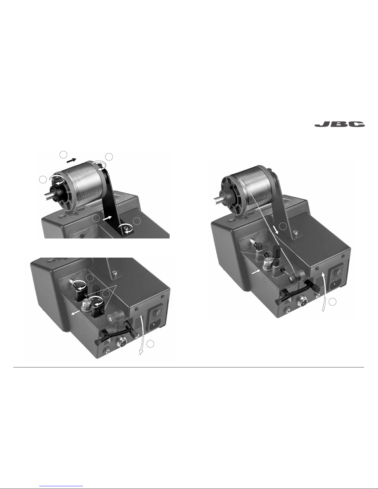
1. Open dragging mechanism
2. Place the guide set and
tighten the screws
Guide Set
3. Take the solder wire from the reel until the guide tube start
4. Close the dragging mechanism
Guide Tube
Start
3
1
2
2
Reel Stand Assembly
Adjusting System Assembly
Page 4
+
LOADING
SOLDER WIRE
+
-
ww w.jb ct oo ls. co m
6 7
A
B
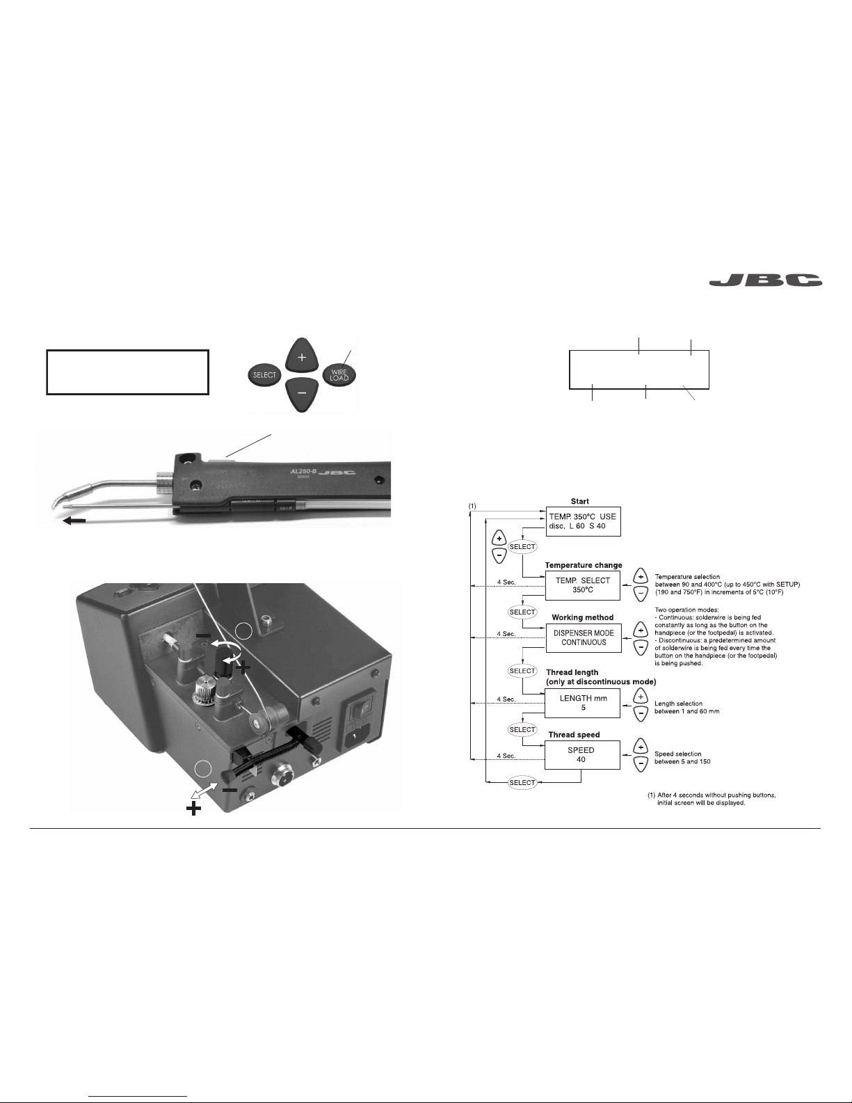
5. Connect the handpiece to the station and switch it on. With the handpiece out of the stand, press
the WIRE LOAD key till the solder leaves by the end of the guide tube.
Fast wire
dragging
Solder wire dragging button
A. Adjust the dragging strength
to allow the forwarding of the
solder wire and to avoid stall
and or clogging situations when
any cause arises
B. Tighten the dragging
mechanism
Clutch Regulation
Control Screen
There are 4 tool status:
USE (Use). The tool is ready to work.
STD (Stand). The tool is placed in the stand but still not in the sleep mode.
SLP (Sleep). The tool is in the sleep mode in the stand, its temperature has dropped till the sleep temperature.
OL. The power circuit is overheated. The power is temporarily not supplied.
TEMP. 230ºC USE
disc. L 10 S 11
Tool temperature
Tool status
Length of
wire
Speed
Working method
Page 5

ww w.jb ct oo ls. co m
8 9
CONTINUE ON NEXT PAGE
Parameters Modification of the Tool and the Station
To enter into this mode, you must hold the SELECT key for 3 seconds.
Page 6

ww w.jb ct oo ls. co m
10 11
Page 7

1
3
4
2
ø 0,4
ø 0,6
1,8x0,8
ø 0,8
4,8x1,5
1,2x0,7
3,2x1,5
ø 2,2
2,2 x 1
1,2x0,7
2,2x1
4,8x1,5
ø 2,2
ø 3,8
2,2x1
ø 1,7
ø 1
ww w.jb ct oo ls. co m
8-10 mm
12 13
1. Loosen the cartridge screw to release it.
Place the new cartridge in the Auto-feed iron.
Alignment
Guide tube
Ref . 0002401 - Ø 0,9 - 1,1 mm
Changing cartridge
For a safe cartridge change, unplug the tool or turn the station off before following these guidelines:
2. Align the tip of the cartridge with the
solder Guide tube.
Important: It is essential to insert the
cartridge till the end for a good connection.
Use the mark as reference. Tighten the
cartridge screw.
3. You must leave a gap of 8-10 mm
between the tip and the end of the Guide
tube.
4. Loosen the guide screw.
Adjust the Guide tube and tighten
the screw.
Adjustable Stand
Adjust the tool holder angle to suit your work position. The AL250-B Auto-feed Iron works with C250 cartridge range. Find the model that best suits your
soldering needs in www.jbctools.com
Compatible Cartridges
C250-420 C250-401
C250-405
C250-402
C250-406
C250-403
C250-412C250-404 C250-418
C250-409 C250-410
C250-413C250-407 C250-408 C250-411 C250-414 C250-415
Note: All the cartridges shown are actual size.
Page 8

ww w.jb ct oo ls. co m
14 15
Accessories
Fume Extr actor
Ref. F4468
Suppor t
Ref. AL-IA
Optional Guide set
Ref. 0002399 - Ø 0.4 - 0. 5 mm
0002402 - Ø 0.6 - 0.8 mm
0002843 - Ø 1.1 - 1.5 mm
0013915 - Ø 1.6 - 1.8 mm
Driver Ge ar
Ref. 0002863
*Only included in the Ø 1.1 - 1.5 / Ø 1.6 - 1.8
Guide set for a correct draggi ng of the solder
wire.
Improve thermal transfer by cle aning the tip after each solder j oint.
Tip Cleaner
Brass Wool
Ref. CL6210
Splashg uard
Non-slip b ase
Sponge
Ref. S0354
Wiper
Ref. CL0236
Very effe ctive cleaning m ethod.
It leaves a small l ayer of
solder on the t ip to
prevent oxidati on
between c leaning
and rewetting.
It prevents splashing of
solder par ticles whe n using
the brass wool.
No need to hold the bas e
while cleaning tips.
The least har mful cleaning m ethod.
Keep the sponge d amp with
distilled wate r when working to
avoid tip wear.
A temperature resistant receptacle lets the
operator rem ove excess solder by ge ntly
tapping or wiping.
Tapping: Wiping:
Tap gently to remove
excess solde r.
Use the slots to
remove remain ing
particl es.
Optional
Inox Wool
Ref. CL6205
Metal Br ush
Ref. CL6220
Tip-Tinner
Ref. TT-A
Sand
Ref. CL6211
Page 9

ww w.jb ct oo ls. co m
16 17
Safety
- Do not use the uni ts for any purpose other than solde ring or rework. Inc orrect use may c ause fire.
- The power cord must be plugged into approved bases. Be sure that it is properly grounded
before use. When unplugging it, hol d the plug, not the wire.
- Do not work on ele ctrically li ve parts.
- The tool should be placed in the s tand when not in us e in order to activate the sleep mode.
The soldering ti p, the metal part of the to ol and the stand may s till be hot even when th e station is
turned off. Handle w ith care, includ ing when adjus ting the stand position.
- Do not leave the ap pliance unat tended when it i s on.
- Do not cover the ven tilation grills. H eat can cause i nflamable products to ignite.
- Use a “non resid ue” classifi ed flux and avoid c ontact with skin or eyes to prevent irritation.
- Be careful with the fumes prod uced when sol dering.
- Keep your work place clean a nd tidy. Wear appropria te protective glasse s and gloves whe n
working to avoid perso nal harm.
- Utmost care mu st be taken with liq uid tin waste which c an cause burn s.
- This appli ance can be use d by children over the a ge of eight and als o persons with re duced
physical, sensor y or mental ca pabilities or lack of experie nce provided that they have been give n
adequate super vision or instr uction conce rning use of the ap pliance and un derstand the h azards
involved. Children mu st not play with the ap pliance.
- Maintenanc e must not be carr ied out by childr en unless sup ervised.
It is imperative to follow safe ty guideli nes to prevent ele ctric
shock, inj ury, fire or expl osion.
Before carr ying out mai ntenance, always al low the equipme nt to cool.
- Clean the station screen with a g lass cleane r
or a damp cloth.
Clean
periodically
- Use a damp cloth to cl ean the casing a nd
the tool. Alcoh ol can only be use d to clean
the metal par ts.
- Periodica lly check that th e metal parts of
the tool and stan d are clean so that th e
station can de tect the tool status.
- Maintain tip s urface cle an and tinned pr ior
to storage in order to avoi d tip oxidation.
Rusty and dirty sur faces reduce h eat
transfer to the so lder joint.
- Periodica lly check all c ables and tubes.
Maintenance
1. Pull off the fuse holder and remove th e
fuse. If nece ssary use a too l to lever it off.
2. Press the new fuse into the fuse ho lder
and replace i t in the station.
- Replace a bl own fuse as follows:
- Replace any d efective or dama ged pieces. Us e original JBC s pare parts on ly.
- Repairs sh ould only be performed by a JBC a uthorized techn ical serv ice.
Page 10

ww w.jb ct oo ls. co m
18 19
Exploded View
Page 11

0016966-0915
www.jbctools.com
AL-1A 120V 50/60Hz. Input fuse: 2A. Output: 23.5V
AL-2A 230V 50/60Hz. Input fuse: 1A. Output: 23.5V
AL-9A 100V 50/60Hz. Input fuse: 2A. Output: 23.5V
- Total weight: 5.8 kg (12.9 lb)
- Dimensions: 195 x 200 x 240 mm
- Output Peak Power: 130W
- Temperature range: 90 - 450°C (190 - 840°F) (±5%)
- Complies with CE standards on electrical safety, electromagnetic compatibility
and ESD protected housing “skin effect”
- RoHS compliant
- Equipotential connector and the tool tip are connected to station mains ground supply
for ESD protection
- Diameter of solder wire: 0.4 - 1.8 mm / 0.02 - 0.07 in
Complies with CE standards
ESD protected housing “skin effect”
Warranty
JBC’s 2 year warranty covers this equipment
against all manufacturing defects, including the
replacement of defective parts and labour.
Warranty does not cover product wear due to use
or mis-use.
In order for the warranty to be valid, equipment
must be returned, postage paid, to the dealer
where it was purchased.
This product should not be thrown in the garbage.
In accordance with the European directive 2002/96/EC, electronic equipment at the end of their life
must be collected and returned to an authorized recycling facility.
Specifications
 Loading...