

Page 1

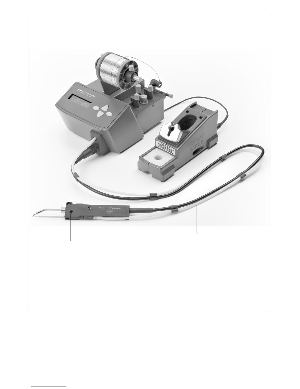
AL 2500
GUIDE SETS FOR
Index Page
English 1
Español 3
Deutsch 5
Reference Guide
Page 2

Page 3
Guide tube screw
Tornillo de sujección del tubo guía
Befestigungsschraube des Führungsschlauch
Guide set
Conjunto guía
Zuleitungsgarnituren
Page 4

Page 5

6
Cartridge and
electric connection
screw
WARNING: It is esential
to tighten this screw for
the tool to function.
Guide tube screw
5
Guide tube
8 - 10 mm
Alignment
4
1
ENGLISH
For a proper installation, please proceed as follow:
1. Place the control in the position showed in the
graphic in order to open the dragging mechanism.
2. Loosen the solder reel guide screws of the
control unit.
3. Place the tubes and guides set in the control
unit. Note: with the 0,4 - 0,5 ø guide set is necessary
to extract the wire of protection.Tighten the screws.
Guide sets
There are 4 guide sets, for the following solder
thread diameters:
- 0,4 - 0,5 ø Ref. 0002399
- 0,6 - 0,8 ø Ref. 0002402
- 0,9 - 1 ø Ref. 0002401
- 1,1 - 1,5 ø Ref. 0002843
Each set is supplied with 2 thread guides, the
leading tube and the exit guide in the iron.
4. Place the solder feed handpiece.
¡Warning!
As a safety measure and in order to avoid burns,
when the cartridge is manipulated you must switch
off the station or disconnect the solder feed
handpiece. Take into account that it only takes a
few seconds to reach the working temperature.
5. Place the guide tube for the solder threat in the
solder feed handpiece. You must leave a distance
between 8-10mm from the tip of the cartridge and
the end of the guide tube end. Tighten the screw of
the guide tube.
6. Point the tip of the cartridge to the solder guide
tube exit. Tighten the cartridge screws.
Important.
- It is essential to insert the cartridge till the
end for a good connection. Take the mark
as reference.
3
3
1
1
2
2
Page 6

2
ENGLISH
7. Take the solder thread from the solder reel until
the guide tube start.
Place the control in the indicated position in order
to close the dragging mechanism.
Dragging system's wheel replacement
If you uses solder threat diammeter within1,1 and
1,5 you must use guide set ø1,1-ø1,5 Ref.
0002843.
This accessory is supplied with a wheel for the
dragging system Ref. 0002863. The wheel must
replace the one that is supplied with the station,
eventhough when only threat diammeter 1,5mm
are will be used.
In order to replace it, you only need to move to the
right side the opening command of the dragging
system and separate the wheel from its place at
the same time. Place the new wheel and put the
command at its initial position.
7
7
Thread dragging
button
Fast dragging thread
Connect the handpiece to the station and switch it
on. Press the WIRE LOAD key (Fast dragging
thread) till the solder leaves by the end of the guide
tube. Display will show the message "LOADING
SOLDER WIRE".
Ref. 0002863
Page 7

Tornillo de sujección del tubo guía
5
Tubo guía
8 - 10 mm
3
ESPAÑOL
Conjuntos guía
Existen 4 conjuntos guía + tubo, para los
siguientes diámetros de hilo de soldadura:
- 0,4 - 0,5 ø Ref. 0002399
- 0,6 - 0,8 ø Ref. 0002402
- 0,9 - 1 ø Ref. 0002401
- 1,1 - 1,5 ø Ref. 0002843
Cada conjunto se compone de 2 guías hilos, el tubo
de conducción y la guía de salida en el soldador.
Para su instalación siga los pasos que se indican
a continuación:
1. Ponga el mando en la posición señalada en el
gráfico para que se abra el mecanismo de arrastre.
2. Afloje los tornillos de sujección de las guías
del hilo de estaño de la unidad de control.
3. Coloque el juego de tubos y guías en la unidad de
control. Nota: con el conjunto guia de 0,4 - 0,5 ø es
necesario extraer el hilo de protección que hay en
su interior. Apriete los tornillos de sujección.
5. Coloque el tubo guía para el hilo de estaño en
el lápiz alimentador. Deje una separación de
unos 8 a 10mm entre el extremo de la punta del
cartucho y el final del tubo guía. Apriete el
tornillo de sujección del tubo guía.
Importante.
- Es indispensable introducir el cartucho hasta
el fondo, para conseguir una buena conexion.
Utilice la marca como referencia.
3
3
1
1
2
2
Alineación
4
4. Coloque el cartucho en el lápiz alimentador.
¡Atención!
Como medida de seguridad y para evitar
quemaduras, cuando manipule el cartucho debe
apagar la estación o desconectar el lápiz
alimentador de la estación. Tenga en cuenta que
en tan sólo unos segundos el cartucho alcanza la
temperatura de trabajo.
6
Tornillo de sujección
y conexión eléctrica
del cartucho
ATENCION: para que el
soldador funcione es
indispensable apretar
este tornillo.
6. Oriente la punta del cartucho hacia la salida
del tubo guía de estaño. Apriete el tornillo de
sujección del cartucho.
Page 8

4
ESPAÑOL
7. Pase el hilo de estaño desde la bobina hasta
el inicio de los tubos de guía.
Ponga el mando en la posición indicada para
que se cierre el mecanismo de arrastre.
Cambio del piñon del sistema de arrastre
Si utiliza hilo de estaño con diámetro entre 1,1 y
1,5 debe usar el conjunto guía ø1,1-ø1,5 Ref.
0002843.
Este accesorio se suministra con un piñon para
el sistema de arrastre Ref. 0002863. El piñon
debe sustituir al que se incluye de origen en la
estación, aunque sólamente cuando se utilice
hilo de diámetro de 1,5mm.
Para cambiarlo basta con desplazar hacia la
derecha el mando de apertura del sistema de
arrastre y al mismo tiempo quitar el piñon de su
alojamiento. Se coloca el nuevo piñon y por
último se vuelve a dejar el mando en su posición
inicial.
Ref. 0002863
7
7
Pulsador avance
hilo estaño
Avance rápido del hilo
Conecte el lápiz a la estación y pongala en
marcha. Pulse en el botón WIRE LOAD (avance
rápido del hilo) hasta que salga estaño por el
extremo del tubo guía. En el display se muestra
el mensaje "CARGANDO HILO SOLDADURA".
Page 9

6
Befestigungsschraube
und elektrischer
Anschluss der
Kartusche
VORSICHT: Diese Schraube
muss unbedingt angezogen
werden, sonst kann der
Lötkolben nicht
funktionieren.
5
DEUTSCH
Zuleitungsgarnituren
Es gibt 4 Zuleitungsgarnituren + Schlauch für
Lötdraht mit den folgenden Durchmessern:
- 0,4 - 0,5 ø Ref. 0002399
- 0,6 - 0,8 ø Ref. 0002402
- 0,9 - 1 ø Ref. 0002401
- 1,1 - 1,5 ø Ref. 0002843
Jede Garnitur besteht aus 2 Drahtführungen, dem
Führungsschlauch und der Ausgangsführung am
Lötkolben.
Befolgen Sie bei ihrem Einbau die anschließend
genannten Arbeitsschritte:
1. Bringen Sie den Regler in die auf der Abbildung
gezeigte Stellung, damit sich der
Vorschubmechanismus öffnet.
2. Lockern Sie die Befestigungsschrauben der
Zinndrahtführungen an der Steuereinheit.
3. Bringen Sie die Führungsschlauch-Garnitur an
der Steuereinheit an. Anmerkung: bei der
Zuleitungsgarnitur 0,4 - 0,5 ø muss zunächst der in
ihrem Inneren vorhandene Schutzdraht
herausgezogen werden. Ziehen Sie die
Befestigungsschrauben fest.
Wichtig.
- Für eine gute Verbindung ist es
ausschlaggebend, die Kartusche bis zum
Anschlag einzustecken. Orientieren Sie sich
dabei an der Markierung.
6. Richten Sie die Kartuschenspitze auf das Ende
des Zinnführungsschlauch aus. Ziehen Sie die
Befestigunsschraube der Kartusche an.
3
3
1
1
2
2
Befestigungsschraube des Führungsschlauch
5
Führungsschlauch
8 - 10 mm
5. Stecken Sie den Führungsschlauch für den
Zinndraht in das Zuführungs-Handstück. Lassen Sie
dabei einen Abstand von etwa 8 bis 10 mm zwischen
dem Ende der Kartuschenspitze und dem Ende des
Führungsschlauch. Ziehen Sie die
Befestigungsschraube des Führungsschlauch fest.
Ausrichtung
4
4. Bauen Sie die Kartusche in das Zuführungs-
Handstück ein.
Vorsicht!
Als Vorsichtsmaßnahme und um Verbrennungen zu
vermeiden, müssen Sie die Station abschalten oder
das Zuführungs-Handstück aus der Station abziehen,
wenn Sie Arbeiten an der Kartusche ausführen.
Denken Sie daran, dass die Kartusche in nur wenigen
Sekunden die Arbeitstemperatur erreicht.
Page 10

6
DEUTSCH
7. Führen Sie den Zinndraht von der Spule bis zum
Beginn der Führungsschläuche.
Bringen Sie den Regler in die angegebene
Stellung, damit sich der Vorschubmechanismus
verriegelt.
Zahnradwechsel des Vorschubsystems
Wenn Sie Zinndraht mit einem Durchmesser
zwischen 1,1 und 1,5 verwenden, müssen Sie die
Führungsgarnitur ø1,1-ø1,5 Ref. 0002843
benutzen.
Dieser Zubehörartikel wird mit einem Zahnrad für
das Vorschubsystem Ref. 0002863 ausgeliefert.
Das Zahnrad muss das werksmäßig in die Station
eingebaute ersetzen, allerdings nur dann, wenn
Draht mit dem Durchmesser 1,5 verwendet wird.
Um es auszuwechseln, muss man nur den
Öffnungsregler des Vorschubsystems nach rechts
bewegen und gleichzeitig das Zahnrad aus seinem
Gehäuse nehmen. Man setzt das neue Zahnrad
ein und zuletzt bringt man den Regler wieder in
seine Ausgangsstellung.
7
7
Ref. 0002863
Taste Zinndrahtvorschub
Schneller Drahtvorschub
Schließen Sie das Handstück an die Station an und
schalten Sie diese ein. Betätigen Sie die Taste
WIRE LOAD (schneller Drahtvorschub) solange,
bis Zinn am Ende des Führungsschlauch
herauskommt. Auf dem Display wird die Meldung
"LOADING SOLDER WIRE" angezeigt.
 Loading...