

Page 1
AL250
SOLDERING IRON
www.jbctools.com
Page 2
2
AL250 / SOLDERING IRON
AL250-B
SOLDERING IRON
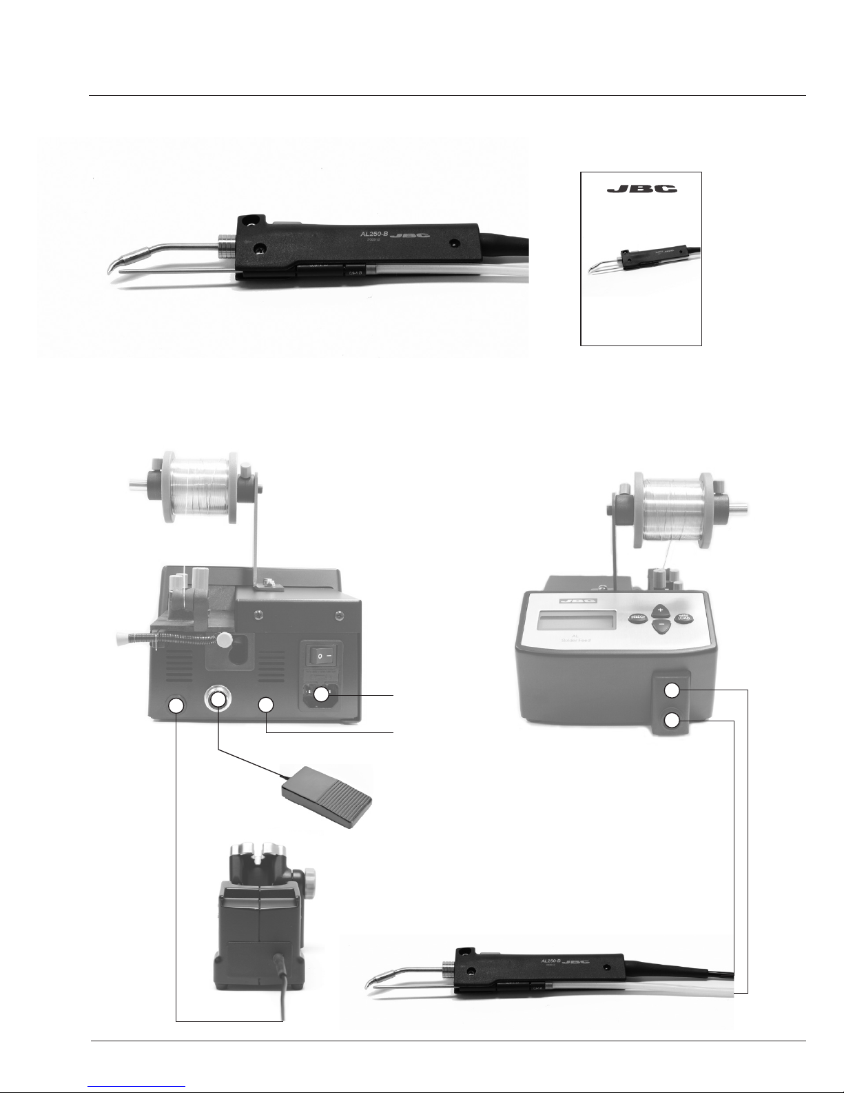
INSTALLATION
AL250-B
SOLDERING IRON
MANUAL
AL-2A / AL-1A
AL-9A / AL-2AA
SOLDER FEED
STATION
AL-SD
STAND
Power cord
socket
Equipotential
connection
0964551
Pedal
(optional)
AL250
SOLDERING IRON
www .jbc tool s.c om
Page 3

3
CHANGING THE HANDPIECE’S CARTRIDGE
ACCESSORIES AL-IA
HANDS-FREE SOLDERING
ARM AND FUME
EXTRACTOR
F4468
FUME EXTRACTOR
- Loosen the cartridge screw (1) to release the cartridge.
- Place the cartridge in the solder feed handle.
Important: It is essential to insert the cartridge till the end for a good connection.
Use the mark as reference.
- Align the tip of the cartridge with the solder guide tube (2). Tighten the cartridge screw (1).
- You must leave a gap of 8-10 mm between cartridge tip and the end of the guide tube (4). Loosen the
guide screw (3). Adjust the guide tube and tighten screw (3).
Cartridge screw
Guide tube screw
Alignment
1
4
3
2
8-10 mm
Page 4

WARRANTY
JBC’s 2 years warranty guarantees this equipment against all manufacturing defects, covering the replacement of defective parts and
all necessary labour.
Warranty does not cover product wear due to use or mis-use.
In order for the warranty to be valid, equipment must be returned,
postage paid, to the dealer where it was purchased enclosing this
fully filled in, sheet.
www.jbctools.com
SERIAL Nº
STAMP OF DEALER
DATE OF PURCHASE
0012317-0213
This product should not be
thrown in the garbage.
All the cartridges shown are
actual size.
Consult our wide range of
cartridges with more than
300 references in
www.jbctools.com
For special cartridges
contact with our distributor.
C250 CARTRIDGE RANGE
ø 0,6
1,8x0,8
ø 0,8
4,8x1,5
1,2x0,7
3,2x1,5
ø 2,2
2,2 x 1
1,2x0,7
2,2x1
4,8x1,5
ø 2,2
ø 3,8
2,2x1
ø 1,7
ø 1
C250-401
C250-405C250-402 C250-406C250-403 C250-412
C250-404
C250-418C250-409 C250-410
C250-413C250-407 C250-408 C250-411
C250-414 C250-415
 Loading...