

Page 1
SOLDER FEED STATION
Index
Page
English 1
Español 8
Deutsch 15
Reference Guide
AL
Page 2

Page 3
1
ENGLISH
We appreciate the trust you have placed in JBC in purchasing this station.
It is manufactured to the strictest quality standards in order to give you the best possible
service. Before turning on your station, we recommend you read these instructions
carefully.
Technical specifications
- AL 230V control unit Ref. AL-2A
Input: 230V 50Hz. Output: 24V
- AL 120V control unit Ref. AL-1A
Input: 120V 60Hz. Output: 24V
- AL 100V control unit Ref. AL-9A
Input: 100V 60Hz. Output: 24V
- Power: 60W.
- ESD protected housing.
Typical surface resistance: 105-1011Ohms/square.
Solder feed station
AL 230V Ref.AL-2A
AL 120V Ref.AL-1A
AL 100V Ref.AL-9A
Solder feed stand AL
Ref. AL-SA
Solder feed handpiece
Ref. AL-A
Cartridge
Control unit
Guide set for solder thread 0,9 - 1 ø
Ref. 0002401
- Complies with CE standards on electrical safety,
electromagnetic compatibility and antistatic
protection.
- Equipotential connector and the tool tip are connected to station mains ground supply for ESD
protection.
- RoHS compliant.
- Total weight of unit: 6,1 Kgs (13,5lbs).
This product should not be thrown in the
garbage.
Page 4
ENGLISH
2
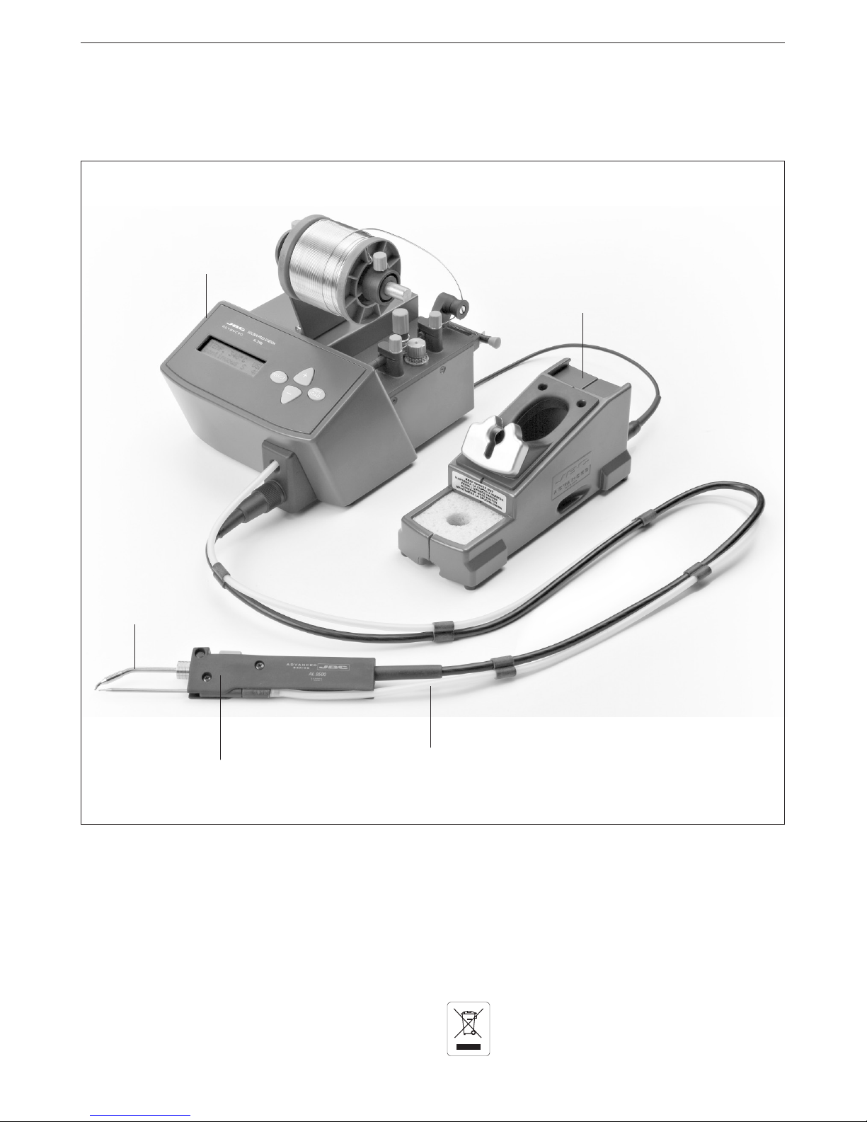
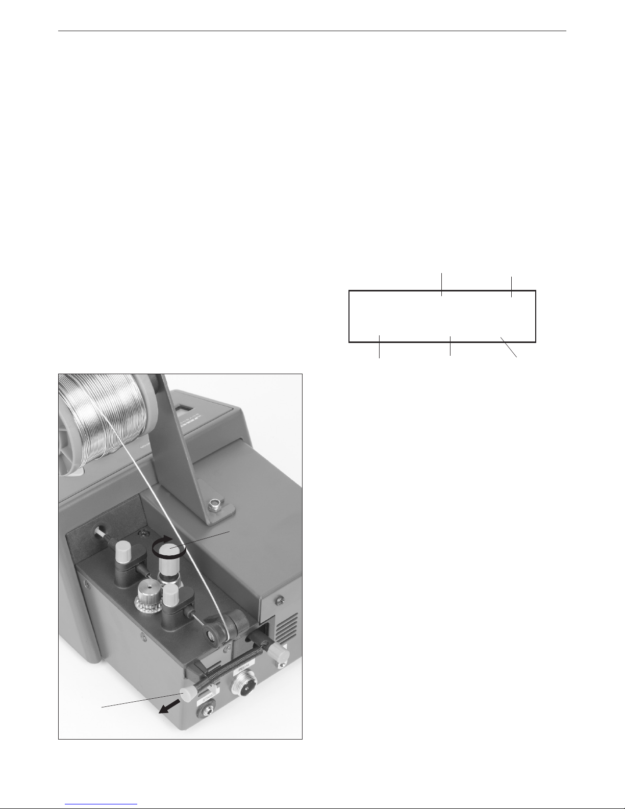
Stand connector
Pedal connector or
external command
Equipotential
connector
Solder thread guide tube
Dragging to adjust the solder
thread strength
Command to release the pressure of the wheels of the solder
dragging mechanism
Pressure regulation of
the spring tightening
control
AL Solder feed station
- AL 230V Ref. AL-2A
- AL 120V Ref. AL-1A
- AL 100V Ref. AL-9A
This station allows you to keep the hand that would
normally hold the solder wire free. If you plan to
use accessories such as pedal switch and stand
arm, then both hands will remain free. This system
is also designed to work as an automatic solder
feed station.
The system includes:
- Control unit.
- Solder feed handpiece Ref. AL-A
with the 250-403 cartridge Ref. C250403
- AL solder feed stand Ref. AL-SA
RECOMMENDATIONS FOR USE
For soldering
- Preferably select a temperature below 350°C
(662ºF). Excess temperature reduce tip life.
- The tip must be well tinned for good heat
conduction.
Safety measures
- Place the tool back on its stand in order to let it
cool down before you store it.
- Guide set for solder thread 0,9 - 1 øRef. 0002401
- Connection cable to mains.
- Transport packaging.
Page 5
3
ENGLISH
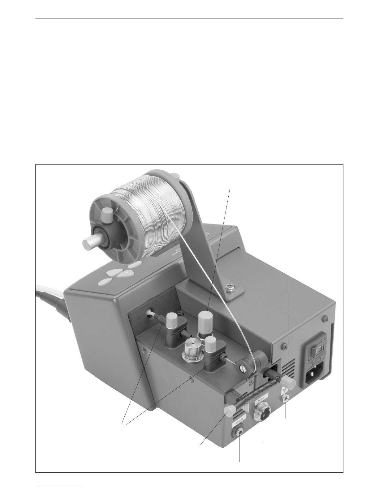
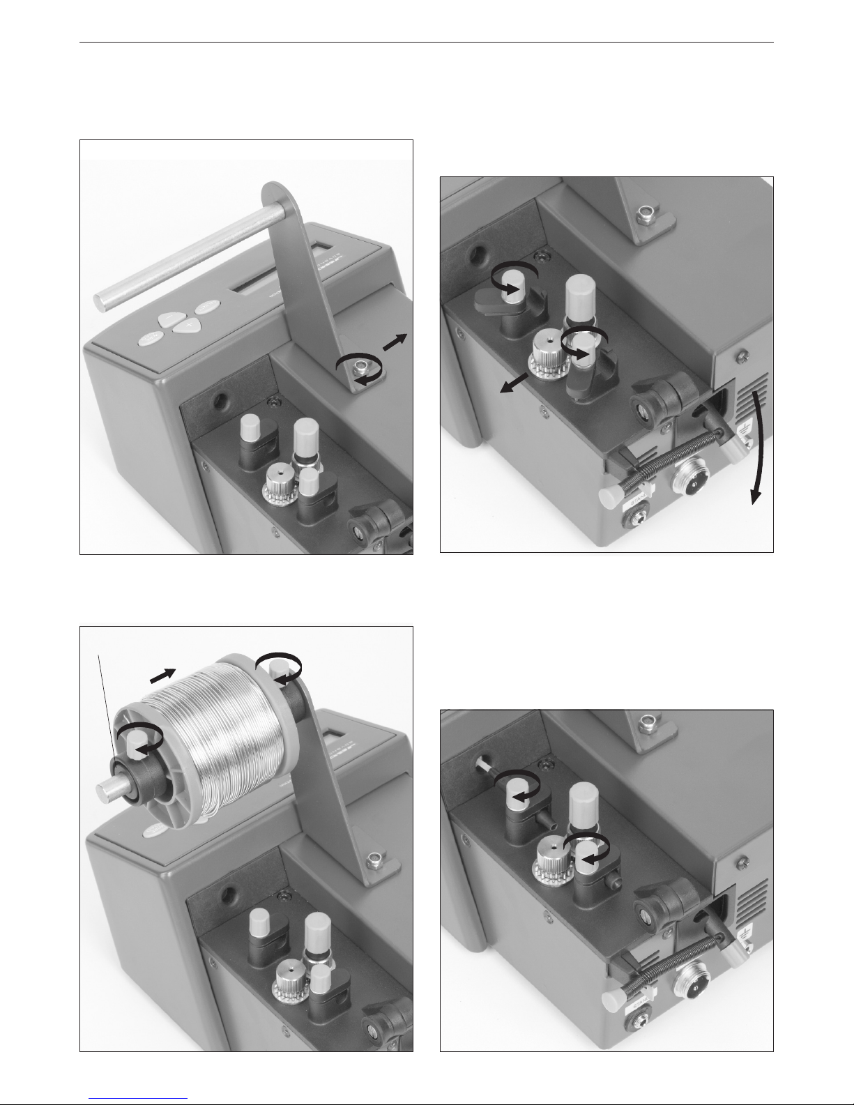
For a proper installation, please proceed as follow:
1. Place the control in the position showed in the
graphic in order to open the dragging mechanism.
2. Loosen the solder reel guide screws of the control
unit.
OPERATION
Place the solder reel in the stand and set the 2
screws.
Place the toolholder metal base and the solder reel
(maximum weight 1kg). Press the 2 screws.
1
1
2
2
3. Place the tubes and guides set in the control unit.
Tighten the screws.
3
3
Toolholder metalbase
The guide set for the solder thread supplied with
the control unit is specially designed for solder reels
diammeter of 0,9 to 1 mm.
If you wish to use other solder reel sizes, you
can order other 3 guide sets as accessory (see
accessories).
Page 6

5
Guide tube screw
Guide tube
8 - 10 mm
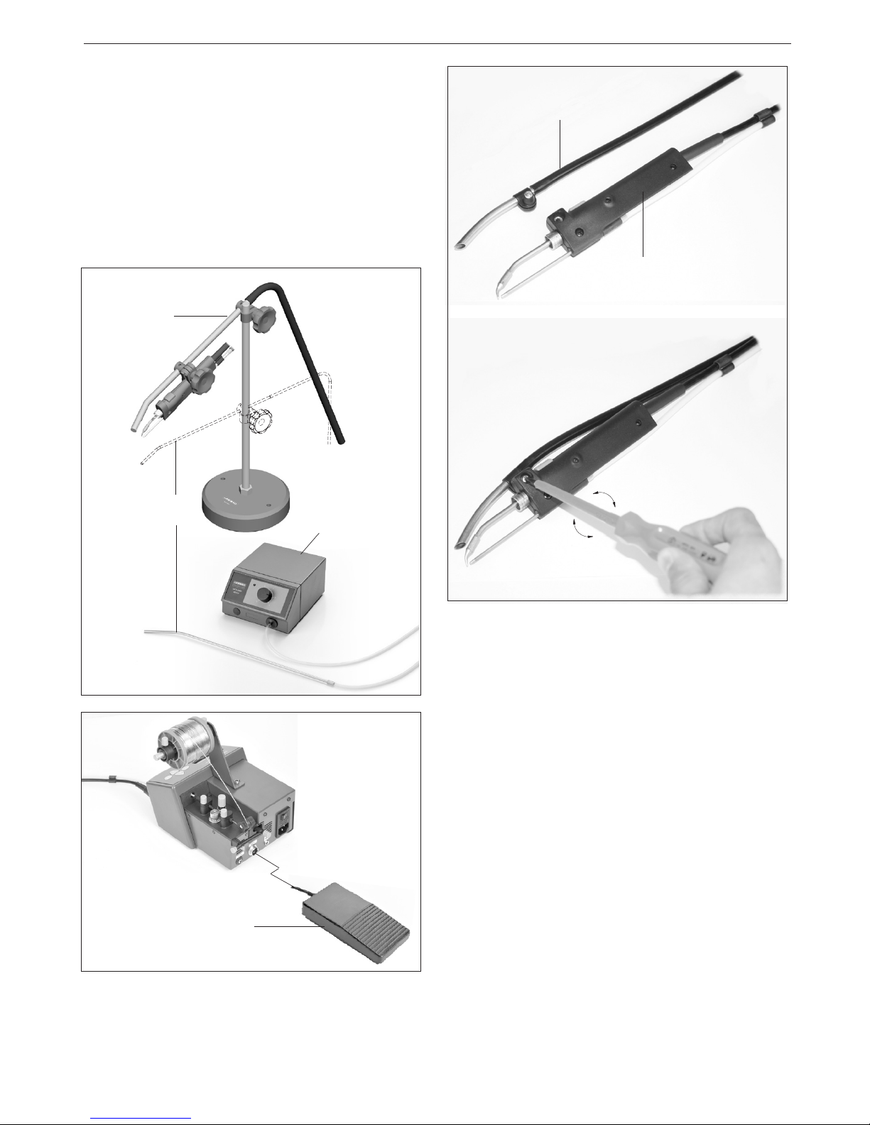
4. Place the solder feed handpiece.
¡Warning!
As a safety measure and in order to avoid burns,
when the cartridge is manipulated you must switch off
the station or disconnect the solder feed handpiece.
Take into account that it only takes a few seconds to
reach the working temperature.
4
ENGLISH
7. Take the solder thread from the solder reel until
the guide tube start.
Place the control in the indicated position in order
to close the dragging mechanism.
5. Place the guide tube for the solder threat in the
solder feed handpiece. You must leave a distance
between 8-10mm from the tip of the cartridge and
the end of the guide tube end. Tighten the screw of
the guide tube.
6. Point the tip of the cartridge to the solder guide
tube exit. Tighten the cartridge screws.
7
7
Connect the handpiece to the station and switch
it on. Press the WIRE LOAD key (Fast dragging
thread) till the solder leaves by the end of the guide
tube. Display will show the message "LOADING
SOLDER WIRE".
Thread dragging
button
Important.
- It is essential to insert the cartridge till the
end for a good connection. Take the mark
as reference.
Fast dragging thread
Alignment
6
C a r t r i d g e a n d
electric connection
screw
4
WARNING: It is esential
to tighten this screw for
the tool to function.
Page 7
ENGLISH
5
CLUTCH REGULATION
The dragging mechanism of the station has one
clutch A.
Its function is to allow the forwarding of the solder
threat when the station is working properly but also
avoid stall and or clugging situations when any
cause arises.
The dragging strengh must be adjusted with the
command A. If we rotate it the dragging strengh
is increased.
A
B
With command B the dragging system is tauten.
The more gap, the more strenght will be obtained.
The station is ready to work.
In order to make a solder joint you only need to
press over the thread dragging button in the handle.
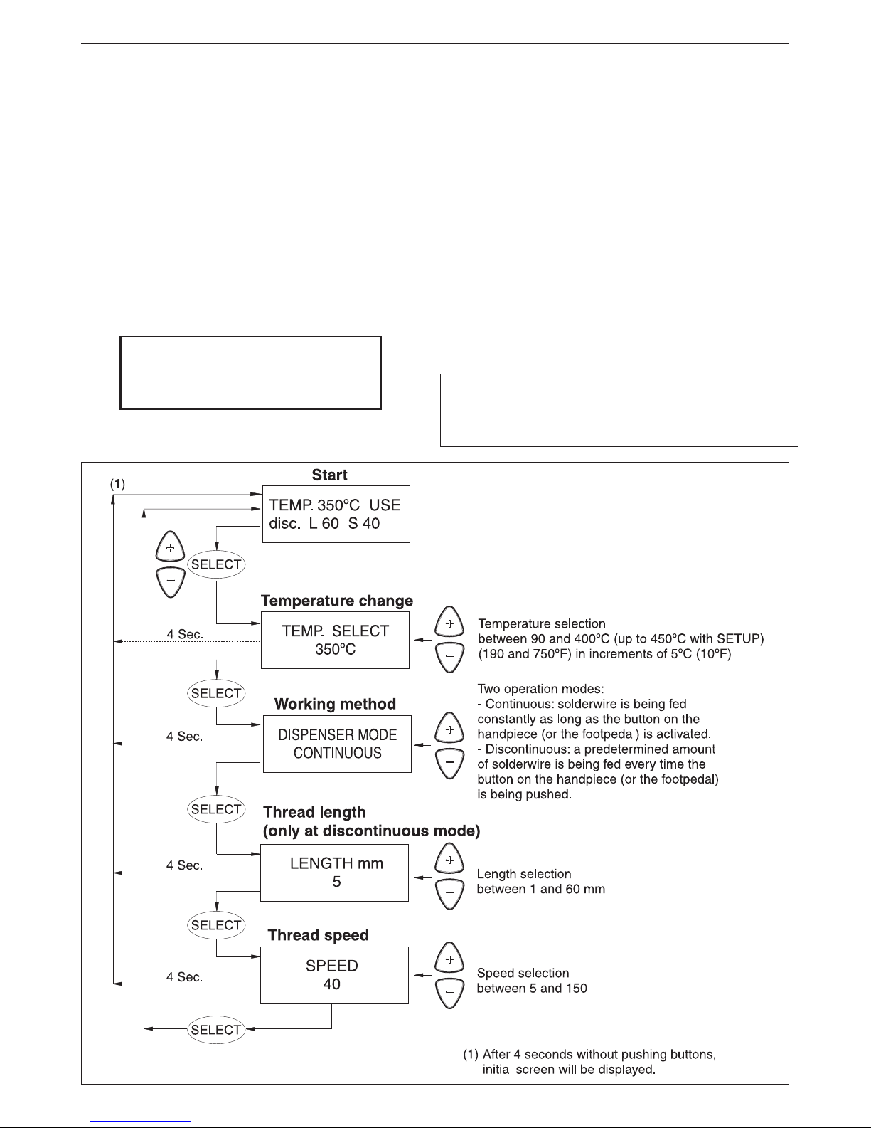
The programm of the station will allow you to modify
all the working parameters. You can display the
parameters with the SELECT key and modify them
with + and - keys.
PROGRAMMING
The system allow us to modify and adjust the following
working parameters directly:
- Temperature between 90 and 400ºC (up to 450ºC
with SETUP).
- Working mode.
- Length thread.
- Speed advance thread.
In order to modify the initial installation parameters
and have access to the counters, you must hold the
SELECT key for 3 seconds.
You will find the operation diagrams are on the
following pages.
STATION DISPLAY
There are 4 tool status:
USE (Use). The tool is ready to work.
STD (Stand). The tool is placed in the stand but still
not in the sleep mode.
SLP (Sleep). The tool is in the sleep mode in the
stand, its temperature has dropped till the sleep
temperature.
OL. The power circuit is overheated. The power is
temporarily not supplied.
TEMP. 230ºC USE
disc. L 10 S 11
Tool temperature
Tool status
Length thread
Speed
Working method
ERROR MESSAGES
No cartridge/tool
Either no tool is connected with the correct cartridge
or the heating element of the cartridge is open.
Wrong tool
The tool which is connected is not valid.
Shortcircuit
The cartridge is in shortcircuit
System stopped by overload (100ºC / 210ºF)
The station has reached a dangerous temperature
and the station stops.
WARNING MESSAGES
Overload (85ºC /185ºF)
When the temperature of the station is close to its
maximum limit, a warning appears for 2 seconds
each 8 seconds as long the station is not cooled
down. The station does not stop.
Page 8
ENGLISH
6
SLEEP FUNCTION
Tool in sleep mode
As son as the soldering iron is left on the stand,
the tip's temperature automatically drops to the
sleep temperature. This is possible because of its
extremely fast thermal response, which allows to
reach the working temperature from the sleep one
without interruption. The oxidation rates on the tin
coating of the tip are drastically reduced, which
increases the tip's lifespan from 2 to 3 times.
To indicate that the tool is in sleep-mode, the display
will show the text SLP.
TEMP. 230ºC SLP
disc. L 10 S 11
HIBERNATION MODE
It is only a "Sleep" second what makes the station
to be in hibernation status, that is to say, the station
keeps runnning but without heating their tools.
It is an state of minimum consumption, but when
it detects that we are using a tool, it turns out
operatively again.
The timing of the hiberation mode is independent
from the sleep mode. It activates by default after
30 minutes.
The hibernation function parameters can be
modified.
In order to take full advantage of the sleep
function and as a security measure, it is
necessary to place the tool in the stand when it
is not being used.
If you would like to change the SLEEP and
HIBERNATION parameters, as any other function,
see page 22.
The sleep function parameters can be modified
using the station program.
Page 9
7
ENGLISH
Accessories
There are other 3 guide sets, apart from the one
supplied with the equipment, for the following solder
thread diameters:
- 0,4 - 0,5 ø Ref. 0002399
- 0,6 - 0,8 ø Ref. 0002402
- 1,1 - 1,5 ø Ref. 0002843
Each set is supplied with 2 thread guides, the leading tube and the exit guide in the iron.
Hands free soldering
stand AL
Ref. AL-IA
The pedal can be plugged to the connector placed
at the rear of the station. Pedal is an option.
Foot switch has the same function as button on the
handle used to feed solder.
Accessory blower
AL
Ref.0003293
Solder feed handpiece
Ref: AL-A
Fume extractor accessory
AL-A Ref: 0004468
You must screw the parts by
the subjection bridle to join the
solder feed handpiece.
You will find all the information about control unit AL
in our web site:
http://www.jbctools.com
JBC reserves the right to make technical changes without prior
notification.
Pedal
Ref. 0964551
AB Air blower
Ref.AB-2A (230V)
Ref.AB-1A (120V)
Page 10

Agradecemos la confianza depositada en JBC al adquirir esta estación. Ha sido
fabricada con las más estrictas normas de calidad para prestarle el mejor servicio.
Antes de poner en marcha el aparato, recomendamos leer con atención las
instrucciones que a continuación se detallan.
8
ESPAÑOL
Datos técnicos
- Unidad de control AL 230V Ref. AL-2A
Entrada: 230V 50Hz. Salida: 24V
- Unidad de control AL 120V Ref. AL-1A
Entrada: 120V 60Hz. Salida: 24V
- Unidad de control AL 100V Ref. AL-9A
Entrada: 100V 60Hz. Salida: 24V
- Potencia: 60W.
- Caja antiestática.
Resistencia típica superficial: 105-1011 Ohms/
cuadro.
Alimentador de estaño
AL 230V Ref.AL-2A
AL 120V Ref.AL-1A
AL 100V Ref.AL-9A
Soporte soldador AL
Ref. AL-SA
Lápiz alimentador estaño
Ref. AL-A
Cartucho
Unidad de control
Conjunto guía para hilo 0,9 - 1 ø
Ref. 0002401
- Cumple la normativa CE sobre seguridad
eléctrica, compatibilidad electromagnética y
protección antiestática.
- El borne equipotencial y la punta del soldador
están en conexión directa a la toma de tierra de
red para protección ESD.
- Cumple la normativa RoHS.
- Peso unidad completa: 6,1 Kgs.
Este producto no debe ser tirado a la basura.
Page 11

ESPAÑOL
9
RECOMENDACIONES DE USO
Para soldar
- Con preferencia seleccione una temperatura
inferior a 350°C. El exceso de temperatura
reduce la vida de la punta.
- La punta debe estar bien estañada para
conducir bien el calor.
Medidas de seguridad
- Coloque la herramienta en su soporte después
de usarla y dejela enfriar antes de almacenarla.
Alimentador de estaño AL
- AL 230V Ref. AL-2A
- AL 120V Ref. AL-1A
- AL 100V Ref. AL-9A
Esta estación permite disponer de la mano que
estaría ocupada con el hilo de soldadura. Si utiliza
accesorios como el pedal y el brazo soporte Ref.
AL-IA permite disponer de las dos manos libres. Se
puede utilizar también como estación en un sistema
automático de soldadura.
Relación de componentes que se entregan:
- Unidad de control.
- Lápiz alimentador de estaño Ref. AL-A
con el cartucho 250-403 Ref. C250403
- AL soporte soldador Ref. AL-SA
- Conjunto guía + tubo
para hilo 0,9 - 1 ø Ref. 0002401
- Cable de conexión a red.
- Envase de transporte.
Conector soporte
Conector pedal o
comando externo
Conector
equipotencial
Guías del hilo
Embrague para el ajuste de la fuerza
de arrastre del hilo
Mando para liberar la presión
de las ruedas de arrastre sobre
el hilo
Regulación presión del
muelle tensor
Page 12

10
ESPAÑOL
Para su instalación siga los pasos que se indican
a continuación:
1. Ponga el mando en la posición señalada en el
gráfico para que se abra el mecanismo de arrastre.
2. Afloje los tornillos de sujección de las guías del
hilo de estaño de la unidad de control.
FUNCIONAMIENTO
Ponga el soporte para la bobina y apriete las 2
tuercas.
Ponga los casquillos portacarrete y la bobina (peso
máximo 1kg). Apriete los 2 tornillos.
1
1
2
2
3. Coloque el juego de tubos y guías en la unidad
de control. Apriete los tornillos de sujección.
3
3
Toolholder metalbase
El juego de tubos y guías que se suministra, es para
hilo de 0,9 a 1mm de diámetro.
Para otros diámetros de hilo ver accesorios.
Page 13

11
ESPAÑOL
5
Tornillo de sujección del tubo guía
Tubo guía
8 - 10 mm
4. Coloque el cartucho en el lápiz alimentador.
¡Atención!
Como medida de seguridad y para evitar quemaduras,
cuando manipule el cartucho debe apagar la estación
o desconectar el lápiz alimentador de la estación.
Tenga en cuenta que en tan sólo unos segundos el
cartucho alcanza la temperatura de trabajo.
7. Pase el hilo de estaño desde la bobina hasta el
inicio de los tubos de guía.
Ponga el mando en la posición indicada para que
se cierre el mecanismo de arrastre.
5. Coloque el tubo guía para el hilo de estaño en el
lápiz alimentador. Deje una separación de unos 8 a
10mm entre el extremo de la punta del cartucho y
el final del tubo guía. Apriete el tornillo de sujección
del tubo guía.
6. Oriente la punta del cartucho hacia la salida del
tubo guía de estaño. Apriete el tornillo de sujección
del cartucho.
7
7
Conecte el lápiz a la estación y pongala en marcha.
Pulse en el botón WIRE LOAD (avance rápido del hilo)
hasta que salga estaño por el extremo del tubo guía.
En el display se muestra el mensaje "CARGANDO
HILO SOLDADURA".
Pulsador avance
hilo estaño
Importante.
- Es indispensable introducir el cartucho hasta
el fondo, para conseguir una buena conexion.
Utilice la marca como referencia.
Avance rápido del hilo
Alineación
6
Tornillo de sujección
y conexión eléctrica
del cartucho
4
ATENCION: para que el
soldador funcione es
indispensable apretar
este tornillo.
Page 14

ESPAÑOL
12
REGULACIÓN DEL EMBRAGUE
El mecanismo de arrastre de la estación dispone
de un embrague A.
Su función es la de permitir el avance del hilo de
estaño cuando la estación funciona correctamente
pero además impide que se formen atascos de
estaño cuando haya alguna causa que impida el
avance del hilo de estaño.
La fuerza de arrastre se debe ajustar con el mando
A. Si giramos en sentido horario aumenta la fuerza
de arrastre.
Con el mando B se tensa el sistema de arrastre.
Cuanto más separado esté, más fuerza se hará.
La estación ya está lista para trabajar.
Para realizar una soldadura sólo debe pulsar sobre
el botón de aportación de estaño del mango.
El programa de la estación le permitirá modificar
todos los parámetros de trabajo. Podrá visulizar
los parámetros con la tecla SELECT y modificarlos
con las teclas + y -.
PROGRAMACIÓN
El sistema permite modificar y ajustar directamente
los siguientes parámetros de trabajo:
- La temperatura entre 90 y 400ºC (hasta 450ºC
con SETUP).
- El modo de trabajo.
- La longitud del hilo.
- La velocidad de avance del hilo.
Para modificar los parámetros de instalación inicial
y tener acceso a los contadores se debe mantener
pulsada durante 3 segundos la tecla SELECT.
En las páginas siguientes tiene los diagramas de
funcionamiento del programa.
DISPLAY DE LA ESTACION
Hay 4 estados de la herramienta:
USE (Use). La herramienta está preparada para
trabajar.
STD (Stand). La herramienta está colocada en el
soporte pero aún no ha entrado en modo "Sleep".
SLP (Sleep). La herramienta está en el soporte y
en modo "Sleep", su temperatura ha bajado hasta
la temperatura de sleep.
OL. Sobrecalentamiento del circuito de poténcia, se
detiene la potencia momentáneamente.
TEMP. 230ºC USE
disc. L 10 S 11
Temperatura
de la herramienta
Estado
herramienta
Longitud hilo VelocidadModo de trabajo
A
B
MENSAJES DE ERROR
No hay cartucho o herramienta (No cartridge/
tool)
No hay herramienta conectada con cartucho
correcto, o el cartucho está abierto.
Herramienta incorrecta (Wrong tool)
La herramienta conectada no es válida.
Cortocircuito (Shortcircuit)
El cartucho está cortocircuitado.
Enfriando (System stopped by overload)(100ºC)
La estación se encuentra a una temperatura
peligrosa y se detiene para enfriarse.
MENSAJES DE WARNING
Sobrecarga (Overload) (85ºC)
Aviso de la temperatura de la estación que está
acercándose al límite máximo, aparece durante 2
segundos en intervalos de 8 segundos mientras
la estación no se haya enfriado. La estación, NO
se detiene.
Page 15

ESPAÑOL
13
SISTEMA SLEEP
Herramienta en reposo
Una de las cualidades de la serie JBC, es que
cuando una herramienta se coloca en el soporte,
la temperatura baja automáticamente hasta la
temperatura de reposo (sleep). Esto es posible,
gracias a la rapidez de su respuesta térmica, que
permite pasar de la temperatura de reposo a la
de trabajo sin interrupción. Con lo cual se evita la
oxidación del estañado de la punta y aumenta de
2 a 3 veces la vida de la punta.
Para indicar que la herramienta está en reposo, en
el display aparece el texto SLP.
TEMP. 230ºC SLP
disc. L 10 S 11
Modo HIBERNACIÓN
Es un segundo Sleep que hace que la estación
entre en hibernación, es decir, la estación sigue
funcionando pero sin calentar sus herramientas.
Es un estado de mínimo consumo, pero que cuando
detecta que se ha cogido una herramienta, vuelve
a estar operativa.
La temporización del modo hibernación es
independiente del modo Sleep, por defecto, se
activa a los 30 minutos.
Los parámetros de la función hibernación son
modificables.
Para beneficiarse del sistema sleep y como
medida de seguridad, es necesario colocar la
herramienta en el soporte cuando no se utilice.
Si desea cambiar los parámetros de SLEEP e
HIBERNACIÓN, así como cualquier otra función,
vea página 22.
Los parámetros de la función sleep se pueden
modificar con el programa de la estación.
Page 16

14
ESPAÑOL
A la estación se le puede conectar el pedal en
el conector que existe en la parte posterior de la
estación.
Cuando se presiona sobre el pedal, equivale a
pulsar el boton de avance del hilo que hay en el
mango del lápiz.
Accesorios
Existen 3 conjuntos guía + tubo, además del que
se suministra con el equipo, para los siguientes
diámetros de hilo de soldadura:
- 0,4 - 0,5 ø Ref. 0002399
- 0,6 - 0,8 ø Ref. 0002402
- 1,1 - 1,5 ø Ref. 0002843
Cada conjunto se compone de 2 guías hilos, el tubo de
conducción y la guía de salida en el soldador.
Lápiz alimentador estaño
Ref: AL-A
Accesorio aspira-humos
AL-A Ref: 0004468
Para unir el lápiz alimentador
de estaño atornillar las piezas
con la brida de sujeción.
Encontrará toda la información sobre la unidad de
control AL en nuestra web:
http://www.jbctools.com
JBC se reserva el derecho de introducir modificaciones sin
previo aviso
Brazo soporte
soldador AL
Ref. AL-IA
Accesorio
soplador AL
Ref. 0003293
Pedal
Ref. 0964551
AB Air blower
Ref.AB-2A (230V)
Ref.AB-1A (120V)
Page 17

Wir danken Ihnen für das JBC mit dem Kauf dieser Station erwiesene Vertrauen. Bei
ihrer Fertigung wurden die strengsten Qualitätsmaßstäbe zugrunde gelegt, so dass
Sie optimale Lötergebnisse erwarten dürfen. Vor Inbetriebnahme des Geräts lesen
Sie bitte die vorliegende Betriebsanleitung aufmerksam durch.
15
DEUTSCH
Lötstation mit Zinnzuführung
AL 230V Ref.AL-2A
AL 120V Ref.AL-1A
AL 100V Ref.AL-9A
Lötkolbenständer AL
Ref. AL-SA
Zinnzuführungs-Handstück
Ref. AL-A
Kartusche
Steuereinheit
Zuleitungsgarnitur für Draht 0,9 - 1 ø
Réf. 0002401
- Er füllt die EG-Sicherheitsvorschriften über
elektrische Sicherheit, elektromagnetische
Kompatibilität und antistatischen Schutz.
- Die Equipotentialausgleichsbuchse und die
Lötspitze sind zum Schutz gegen elektrostatische
Entladungen mit der Erdung des Netzsteckers
verbunden.
- Erfüllt die RoHS-Vorschriften.
- Gewicht der kompletten Anlage: 6,1 kg
Dieses Produkt darf nicht mit dem Hausmüll
entsorgt werden.
Technische Daten
- Steuereinheit AL 230V Ref. AL-2A
Eingangsspannung: 230V 50 Hz
Ausgangsspannung: 24V
- Steuereinheit AL 120V Ref. AL-1A
Eingangsspannung: 120V 60Hz
Ausgangsspannung: 24V
- Steuereinheit AL 100V Ref. AL-9A
Eingangsspannung: 100V 60Hz
Ausgangsspannung: 24V
- Leistung: 60W
- Astatisches Gehäuse.
Typischer Oberflächenwiderstand: 105-1011
Ohm/Quadrat
Page 18

16
DEUTSCH
Lötstation mit Zinnzuführung AL
- AL 230V Ref. AL-2A
- AL 120V Ref. AL-1A
Diese Station ermöglicht es, über die andere Hand
zu verfügen, die eigentlich den Löhtdraht hält. Wenn
man ein Pedal und einen verstellbaren Haltearm für
den Lötkolben Ref. AL-IA einsetzt, hat man sogar
beide Hände frei. Sie kann auch als Station innerhalb
eines automatischen Lötsystems betrieben werden.
Aufstellung der zum Lieferumfang gehörenden
Komponenten:
- Steuereinheit
- Zinnzuführungs-Handstück Ref. AL-A
mit der Kartusche 250-403 Ref. C250403
- AL Lötkolbenständer Ref. AL-SA
EMPFEHLUNGEN FÜR DEN GEBRAUCH
Zum Löten und Entlöten
- Möglichst immer mit Temperaturen unter 350°
C arbei ten. Zu hohe Temperaturen verkürzen
die Standzeit der Lötspitze.
- Damit die Spitze gut die Wärme leitet, muss
sie gut verzinnt sein.
Sicherheitsvorkehrungen
- Nach dem Gebrauch das Werkzeug in seinem
Ständer abstellen und abkühlen lassen, bevor
es aufbewahrt wird.
Ständeranschluss
Anschluss für Pedal oder
externe Steuerung
Equipotentialausg l e i c h s buch se
Führungsschläuche des
Zinndrahts
Kupplung für die Einstellung der
Vorschubkraft des Drahts
Regler zur Entriegelung der
Drahtvorschubkraft
Regulierung des Drucks
der Spannfeder
- Garnitur einer Führungseinheit
für Zinndraht 0,9 - 1 ø Ref. 0002401
- Kaltgerätestecker
- Transportverpackung
Page 19

17
DEUTSCH
Befolgen Sie bei ihrem Einbau die anschließend
genannten Arbeitsschritte:
1. Bringe n Sie den Regler in die auf der
Abbildung gezeigte Stellung, damit sich der
Vorschubmechanismus öffnet.
2. Lockern Sie die Befestigungsschrauben der
Zinndrahtführungen an der Steuereinheit.
FUNKTIONSWEISE
Setzen Sie den Spulenhalter ein und ziehen Sie die
2 Muttern fest.
Setzen Sie die Drahthaspelmuffen und die Spule ein
(Höchstgewicht 1 kg). Ziehen Sie die 2 Schrauben
fest.
3. Bringen Sie die Führungsschlauch-Garnitur
an d er Ste ue rein heit an. Z iehen Sie d ie
Befestigungsschrauben fest.
Die zum Lieferumfang gehörende Garnitur der
Schläuche und Zuführungen eignet sich für Draht
mit einem Durchmesser von 0,9 bis 1 mm.
Für andere Drahtdurchmesser siehe Zubehör auf
der vorherigen Seite.
1
1
2
2
3
3
Toolholder metalbase
Page 20

18
DEUTSCH
5
Befestigungsschraube des Führungsschlauch
Führungsschlauch
8 - 10 mm
4. Bauen Sie die Kartusche in das Zuführungs-
Handstück ein.
Vorsicht!
Als Vorsichtsmaßnahme und um Verbrennungen zu
vermeiden, müssen Sie die Station abschalten oder das
Zuführungs-Handstück aus der Station abziehen, wenn
Sie Arbeiten an der Kartusche ausführen. Denken Sie
daran, dass die Kartusche in nur wenigen Sekunden
die Arbeitstemperatur erreicht.
7. Führen Sie den Zinndraht von der Spule bis zum
Beginn der Führungsschläuche.
Bringen Sie den Regler in die angegebene Stellung,
damit sich der Vorschubmechanismus verriegelt.
5. Stecken Sie den Führungsschlauch für den
Zinndraht in das Zuführungs-Handstück. Lassen
Sie dabei einen Abstand von etwa 8 bis 10 mm
zwischen dem Ende der Kartuschenspitze und
dem Ende des Führungsschlauch. Ziehen Sie die
Befestigungsschraube des Führungsschlauch fest.
6. Richten Sie die Kartuschenspitze auf das Ende
des Zinnführungsschlauch aus. Ziehen Sie die
Befestigunsschraube der Kartusche an.
7
7
Schließen Sie das Handstück an die Station an und
schalten Sie diese ein. Betätigen Sie die Taste WIRE
LOAD (schneller Drahtvorschub) solange, bis Zinn
am Ende des Führungsschlauch herauskommt. Auf
dem Display wird die Meldung "LOADING SOLDER
WIRE" angezeigt.
Taste Zinndrahtvorschub
Wichtig.
- F ür ei ne gu t e Ve rb in d un g i st es
ausschlaggebend, die Kartusche bis zum
Anschlag einzustecken. Orientieren Sie sich
dabei an der Markierung.
Schneller Drahtvorschub
Ausrichtung
6
Befestigungsschraube und
elektrischer Anschluss der
Kartusche
4
V O R S I C H T : D i e s e
Schraube muss unbedingt
angezogen werden, sonst
kann der Lötkolben nicht
funktionieren.
Page 21

DEUTSCH
19
ABSTIMMUNG DER KUPPLUNG
Der Vorschubmechanismus der Station verfügt über
eine Kupplung A.
Ihre Aufgabe ist es, bei reibungslosem Stationsbetrieb
den Zinndrahtvorschub zu gewährleisten, doch
zudem verhindert sie, dass sich Zinnstaus bilden,
wenn der Zinndrahtvorschub aus irgendeinem
Grund beeinträchtigt wird.
Die Vorschubkraft muss mit dem Regler A reguliert
werden. Wenn wir ihn im Uhrzeigersinn drehen, nimmt
die Vorschubkraft zu.
Mit dem Regler B wird das Vorschubsystem gespannt. Je weiter er entfernt ist, umso stärkere Kraft
übt es aus.
Jetzt ist die Station schon einsatzbereit.
Um eine Lötung vorzunehmen, müssen Sie nur die
Taste Zinnzufuhr am Griff betätigen.
Das Programm der Station erlaubt Ihnen, alle
Arbeitsparameter zu ändern. Sie können die
Parameter mit der Taste SELECT anzeigen und mit
den Tasten + und - ändern.
PROGRAMMIERUNG
Das System erlaubt, direkt die folgenden
Arbeitsparameter zu ändern und einzustellen:
- die Temperatur zwischen 90 und 400ºC (bis
450ºC mit SETUP)
- die Betriebsart
- die Drahtlänge
- die Vorschubgeschwindigkeit des Drahts
Um die ursprünglichen Installationsparameter zu
ändern und Zugriff auf die Zähler zu erlangen, die
Taste SELECT 3 Sekunden lang gedrückt halten.
Auf den folge nden Sei ten sehen Sie die
Ablaufdiagramme des Programms.
ANZEIGE DER STATION
Es gibt 4 Werkzeugzustände:
USE (Use). Das Werkzeug ist betriebsbereit.
STD (Stand). Das Werkzeug steht im Ständer,
befindet sich allerdings noch nicht in der Betriebsart
"Sleep".
SLP (Sleep). Das Werkzeug steht im Ständer und
befindet sich in der Betriebsart "Sleep". Seine
Temperatur ist auf die Sleep-Temperatur abgesenkt
worden.
OL. Überhitzung des Hochstromkreises, der
Hochstrom wird zeitweise gestoppt.
TEMP. 230ºC USE
disc. L 10 S 11
Werkzeugtemperatur
Werkzeugzustand
Drahtlänge
Geschwindigkeit
Betriebsart
A
B
FEHLERMELDUNGEN
Kein Werkzeug vorhanden oder Werkzeug
geöffnet (No cartridge/tool)
Es gibt kein mit korrekter Kartusche angeschlossenes
Werkzeug oder die Kartusche ist geöffnet.
Falsches Werkzeug (Wrong tool)
Das angeschlossene Werkzeug ist nicht gültig.
Kurzschluss (Shortcircuit)
In der Kartusche liegt ein Kurzschluss vor.
Abkühlung (System stopped by overload)(100ºC)
Die Station hat eine gefährliche Temperatur erreicht
und hält an, um abzukühlen.
WARNMELDUNGEN
Überhitzung (Overload) (85ºC)
Warnung zur Stationstemperatur, die sich der
Obergrenze annähert. Erscheint 2 Sekunden lang in
Intervallen von 8 Sekunden, solange sich die Station
nicht abgekühlt hat. Die Station hält NICHT an.
Page 22

DEUTSCH
20
Betriebsart Hibernation
Ist eine zweite Stufe der Sleep-Funktion, die dafür
sorgt, dass die Station in eine Art Winterschlaf fällt,
d.h. die Station bleibt weiterhin in Betrieb, heizt
allerdings nicht die Werkzeuge auf. Dies ist ein
Zustand mit äußerst geringem Verbrauch, aber
sobald das Werkzeug in die Hand genommen wird,
ist es erneut einsatzbereit.
Die zeitliche Umschaltung in die Betriebsart
Hib er nat i on ist von der Be triebs art S le ep
unabhängig. Standardmäßig wird sie nach 30
Minuten aktiviert.
Die Parameter der Funktion Hibernation können
geändert werden.
Um das Sleep-System auszunutzen, ist es
erforderlich, das Werkzeug bei Nichtbenutzung
im Ständer abzulegen.
TEMP. 230ºC SLP
disc. L 10 S 11
SLEEP-SYSTEM
Werkzeuge in Standby-Funktion
Eine der Stärken der JBC-Serie liegt darin, dass
die Temperatur automatisch auf die StandbyTemperatur abgesenkt wird, wenn ein Werkzeug
im Ständer abgestellt wird. Das direkte thermische
Ansprechen macht es möglich, ohne Unterbrechung
von der Standby-Temperatur zur Arbeitstemperatur
zu wechseln. Dadurch wird die Oxidierung der
Spitze vermieden und die Lebensdauer der Spitze
um das 2- bis 3 fache verlängert.
Um anzuzeigen, dass sich das Werkzeug im
Standby befindet, erscheint im Display der Text SLP.
Wenn Sie die Parameter für SLEEP und
HIBERNATION sowie irgendeine andere Funktion
ändern möchten, Sehen Sie auf Seite 22.
Die Parameter der Sleep-Funktion lassen sich mit
dem Programm der Station ändern.
Page 23

21
DEUTSCH
Zubehör
Neben der zum Lieferumfang des Geräts gehörenden
Zuleitungsgarnitur gibt es 3 Zuleitungsgarnituren
+ Schlauch für Lötdraht mit den folgenden
Durchmessern:
- 0,4 - 0,5 ø Ref. 0002399
- 0,6 - 0,8 ø Ref. 0002402
- 1,1 - 1,5 ø Ref. 0002843
Jede Garnitur besteht aus 2 Drahtführungen, dem
Führungsschlauch und der Ausgangsführung am
Lötkolben.
Haltearm Lötstation
AL
Ref. AL-IA
An die Station kann das Pedal Ref. 0964551 durch
den auf der Rückseite der Station befindlichen Stecker
angeschlossen werden. Nicht im Lieferumfang
enthalten.
Wenn man das Pedal betätigt, entspricht dies dem
Drücken der Taste Drahtvorschub am Griff des
Handstücks.
Gebläsezubehör
AL
Ref. 0003293
Zinnzuführungs-Handstück
Ref: AL-A
Rauch-Zangenzubehör
AL-A Ref: 0004468
S i e m üs s e n d i e Te i l e
vo m U nt erwer fu ng sza um
schrauben, um das handstück
zu verbinden.
Pedal
Ref. 0964551
Gebläse AB
Ref. AB-2A (230V)
Ref. AB-1A (120V)
Unter dem Web: http://www.jbctools.com finden Sie
die vollständige Information über die Steuereinheit AL.
JBC behält sich das Recht vor, technische oder konstruktive
Änderungen ohne vorherige Ankündigung vorzunehmen
Page 24

22
Page 25

23
Page 26

Page 27

WARRANTY ENGLISH
The JBC 2 years warranty, guarantees
this equipment against all manufacturing
defects, covering the replacement of
defective parts and all necessary labour.
Warranty does not cover product wear
due to use or mis-use.
In order for the warranty to be valid,
equipment must be returned, postage
paid, to the dealer where it was
purchased enclosing this, fully filled
in, sheet.
GARANTIA ESPAÑOL
JBC garantiza este aparato durante 2
años, contra todo defecto de fabricación,
cubriendo la reparación con sustitución
de las piezas defectuosas e incluyendo
la mano de obra necesaria.
Quedan excluidas de esta garantía las
averías provocadas por mal uso del
aparato y desgaste por uso.
Es indispensable para acogerse a
esta garantía el envio del aparato
al distribuidor donde se adquirió, a
portes pagados, adjuntando esta hoja
debidamente cumplimentada.
GARANTIE FRANÇAIS
JBC garantit cet appareil 2 ans
contre tout défaut de fabrication.
Cela comprend la réparation, le
remplacement des pièces défectueuses
et la main d'oeuvre nécessaire.
La garantie ne couvre pas l’usure liée
à l’utilisation et à la mauvaise utilisation
du matériel.
Pour bénéficier de cette garantie il
est indispensable d'envoyer l'appareil
chez le distributeur où il a été acquis,
en ports payés, en joignant cette fiche
dûment remplie.
✂
Page 28

0008879-0210
GARANTIE DEUTSCH
Für das vorliegende Gerät übernimmt
JBC eine Garantie von 2 Jahren, für
alle Fabrikationsfehler. Diese Garantie
schliesst die Reparatur bzw. den
Ersatz der defekten Teile sowie die
entsprechenden Arbeitskosten ein.
Au s ges c hl o s se n vo n die s er
Gar an t ie lei stu ng s ind d ur c h
u n sach g e m ä s s e n Geb r a u c h
hervorgerufene Betriebsstörungen
und normale Gebrauchsabnützungen.
Zur Inanspruchnahme dieser Garantie
muss das Gerät portofrei an den
Vertriebshändler geschickt werden,
bei dem es gekauft wurde. Fügen Sie
dieses vollständig ausgefüllte Blatt bei.
GARANZIA ITALIANO
La JBC garantisce quest'apparato 2
anni contro ogni difetto di fabbricazione,
e copre la riparazione e la sostituzione
dei pezzi difettosi, includendo la mano
d'opera necessaria.
Sono escluse da questa garanzia
le avarie provocate da cattivo uso
dell'apparato e logorio da utilizzo.
Per usufruire di questa garanzia, è
indispensabile inviare, in porto franco,
l'apparato al distributore presso il quale
è stato acquistato, unitamente a questo
foglio debitamente compilato.
DATE OF PURCHASE
FECHA DE COMPRA
DATE D'ACHAT
KAUFDATUM
DATA DI ACQUISTO
STAMP OF DEALER
SELLO DEL DISTRIBUIDOR
CACHET DU DISTRIBUTEUR
STEMPEL DES HÄNDLERS
TIMBRO DEL DISTRIBUTORE
SERIAL Nº
MANUFACTURED BY
JBC Industrias, S.A.
Ramón y Cajal, 3 - 08750 MOLINS DE REI
BARCELONA - SPAIN
Tel.: +34 93 325 32 00 - Fax: +34 93 680 49 70
http://www.jbctools.com e-mail:info@jbctools.com
 Loading...