

Page 1

Index Page
English 1
Español 11
Français 21
Deutsch 31
Italiano 41
AD 4200
DUAL SOLDERING STATION
CE Version
Page 2
ENGLISH
1
We appreciate the confidence you have placed in JBC in purchasing this station.
It is manufactured to the most stringent quality standards in order to give you the
best possible service. Before turning on your station, we recommend you to read
these instructions carefully.
You have pursached a Advanced AD 4200 Control Unit.
In order to complete the soldering station you should choose the suitable handpiece or desoldering
tweezers, the stand and the cartridges for the task to do. The Control Unit is only for handpieces 2010,
2210, 2045, 2245 and the hot tweezers PA 1200 or PA 4200 and corresponding cartridges.
Control Unit
AD 4200 EU Ref. 4200200
AD 4200 UK Ref. 4200201
* Hot tweezers stand
PA 8420
Ref. 0748420
* Hot tweezers
PA 4200
Ref. 4200000
* These elements are not
supplied with the control
unit
* Cartridges for the hot
tweezers PA 4200
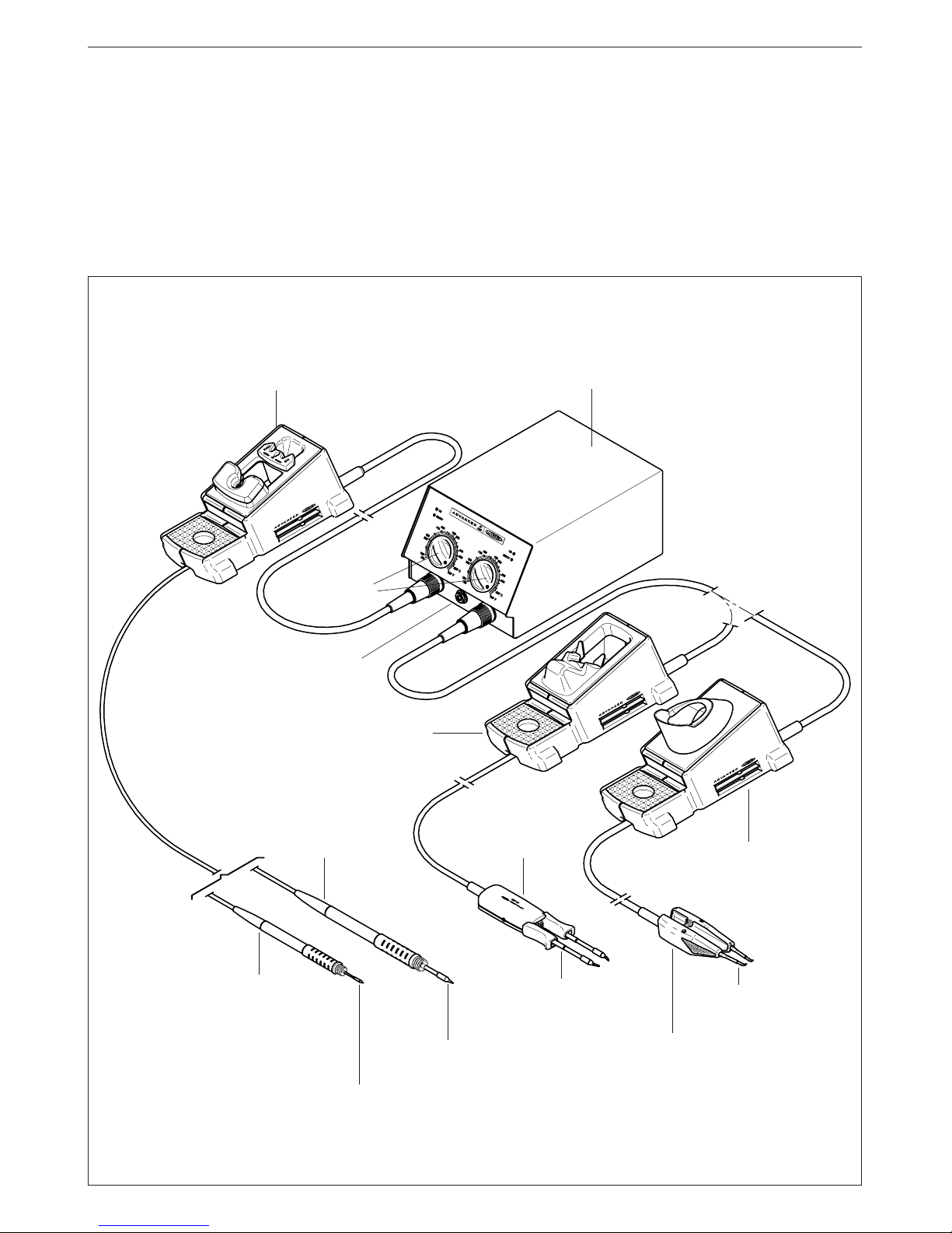
Temperature
selector
Equipotential
terminal
Dual soldering station
* Soldering iron stand
AD 8200
Ref. 0268200
* Handpiece 2010
Ref. 2010000
* Handpiece 2210
Ref. 2210000
* Handpiece 2045
Ref. 2045000
* Handpiece 2245
Ref. 2245000
* Cartridges 2010
* Cartridges 2210
* Cartridges 2045
* Cartridges 2245
* Micro hot tweezers
PA 1200
Ref. 1200000
* Cartridges 1200
* Hot tweezers stand
PA 8100
Ref. 0748100
Page 3

ENGLISH
2
Structure of Advanced soldering stations
system
The Advanced series has basic modules giving
you full flexibility for choosing what you need for
the work in hand, the modules being supplied
separately.
Dual control unit
- AD 4200 EU Ref. 4200200
- AD 4200 UK Ref. 4200201
Model AD 4200 can be used with two tools
simultaneous, either handpieces or desoldering
tweezers. Can be used with either combination of
2010, 2210, 2045 and 2245 handpieces and the hot
tweezers PA 1200 or PA4200.
Handpieces
- 2010 Ref. 2010000
Power: 20W. For high precision work, SMD, etc.
- 2210 Ref. 2210000
Power: 20W. For high precision work, SMD, etc.
- 2045 Ref. 2045000
Power: 50W. For general soldering work.
- 2245 Ref. 2245000
Power: 50W. For general soldering work.
Hot tweezers
- PA 1200 Ref. 1200000
For general precision desoldering with SMD
components.
Power: 40W .
Effective power per cartridge fitted: 20W.
- PA 4200 Ref. 4200000
For general desoldering and soldering work in
professional electronics.
Power: 100W .
Effective power per cartridge fitted: 50W.
Cartridges
- Range of cartridges 2010 (for the 2010 handpiece).
- Range of cartridges 2210 (for the 2210 handpiece).
- Range of cartridges 2045 (for the 2045 handpiece).
- Range of cartridges 2245 (for the 2245 handpiece).
- Range of cartridges for micro hot tweezers PA 1200.
- Range of cartridges for hot tweezers PA 4200.
Stands
- Soldering iron stand AD 8200 Ref. 0268200
- PA 8420 Ref. 0748420
Stand for the hot tweezers PA 4200.
- PA 8100 Ref. 0748100
Stand for the hot tweezers PA 1200 and PA 4200.
For a dual soldering station work properly is
necessary: the dual control unit, a handpiece or the
hot tweezers, and the corresponding stand and
cartridge.
Dual control unit AD 4200
The station is supplied with:
- Control unit.
- Connection cable to mains.
- Instructions manual.
- Transport packaging.
Technical specifications
- Temperature selection from 100 to 371°C (±5%).
- Power: 135W.
- Safety transformer, mains separator and double
isolation, with integrated fuse of temperature
protection.
- Input: 230V 50Hz. Output: 24V.
- Electrical protection Class I.
- Total weight of unit: 5Kg.
- ESD protected housing.
Typical surface resistance: 105-1011Ohms/
square.
- Complies with CE standards on electrical safety,
electromagnetic compatibility and antistatic
protection.
- Equipotential connector is earth connected to the
plug feed of the station.
RECOMMENDATIONS FOR USE
For soldering and desoldering
- Clean the contacts and the printed circuit to
be desoldered of dust or dirt.
- Preferably select a temperature below 350°C.
Excess temperature may cause the printed
circuit tracks to break loose.
- The tip must be well tinned for good heat
conduction. If it has been inoperative for any
length of time, it should be retinned.
Page 4

ENGLISH
3
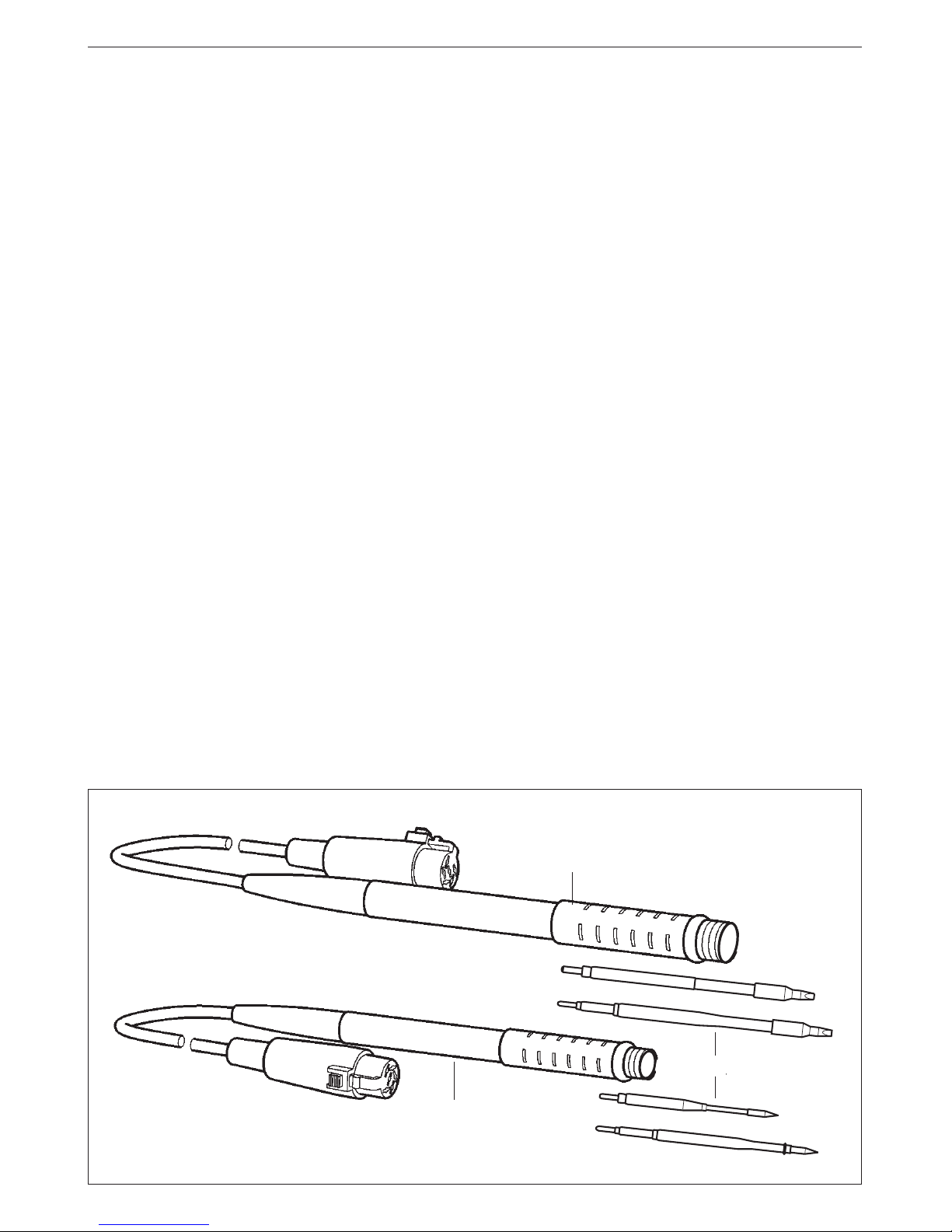
HANDPIECES 2010, 2210, 2045 AND 2245
The following soldering handpieces can be
connected to the AD 4200 station:
- Handpiece 2010 ref. 2010000. Power: 20W. For
high precision work, SMD etc. Available
cartridges 2010: see page 55.
- Handpiece 2210 ref. 2210000. Power: 20W. For
high precision work, SMD etc. Available
cartridges 2210: see page 55.
- Handpiece 2045 ref. 2045000. Power: 50W. For
general soldering work. Available cartridges
2045: see page 54.
- Handpiece 2245 ref. 2245000. Power: 50W. For
general soldering work. Available cartridges
2245: see page 54.
The handpieces and cartridges 2210 and 2245
comply with the MIL-SPEC-2000 referring to the
potential difference between the soldering tip and
ground connection, must be less than 2 mV.
For a soldering handpiece to work properly, the
following components are required: the control
unit, soldering iron stand, one handpiece and one
cartridge.
The soldering iron is connected to the station in the
following way:
The cable connection of the soldering iron is
connected to the plug in the soldering iron stand
AD 8200 and the cable connection of the soldering
iron stand is plugged into the terminal of the
station. Please find the connection plan on page 1.
Handpiece 2045 Ref. 2045000
Handpiece 2245 Ref. 2245000
Handpiece 2010 Ref. 2010000
Handpiece 2210 Ref. 2210000
Cartridges
OPERATION
LED lights
Red LED -ON- when lit, it indicates that the station is
plugged in the mains.
Green LED -READY- when lit, it indicates that the
system is ready and correctly set for working.
The green led light is on after a few seconds, is the
time needed to carry on the self-checking system.
The green light is pulsing when the soldering iron is
in sleep mode.
If the green led is not lit, the reason why, will be one
of the following:
1. The handpiece or the cartridge are not plugged
in.
2. The maximum available power has been
exceeded for too long - e.g. in a very thick
soldering at the high repetition rates.
3. The handpiece or cartridge has a short
circuit or an open circuit.
4. Any other trouble preventing the system from
working properly.
The green led goes off when the cartridge tip
touches the extractor and the station stops the
power supply.
The handpiece will reset itself automatically should
the cartridge short circuit or go open circuit.
Should the handpiece be subject to:
- An electrical surge or the cartridge has not been
fitted correctly.
Please turn the unit off and switch on again to
reset.
Page 5
ENGLISH
4
Sleep function
One of the Series Advanced features is that when
the handpiece is placed in the holder, the
temperature at the tip drops automatically to the
sleep temperature. This function is only possible
because of the quick response time which does
not make the user realise the temperature rise to
reach the selected temperature. Also by this, the
oxidation of the tinning of the tip is considerably
reduced and tip life is extended.
To indicate that the soldering iron is in sleep-mode,
the green led starts pulsing. These parameters can
be modified using the Console AC 2600 Ref. 2600000.
In order to take advantage of the above
mentioned feature and as a security measure,
it is necessary to place the handpiece on stand
when the iron is not being used.
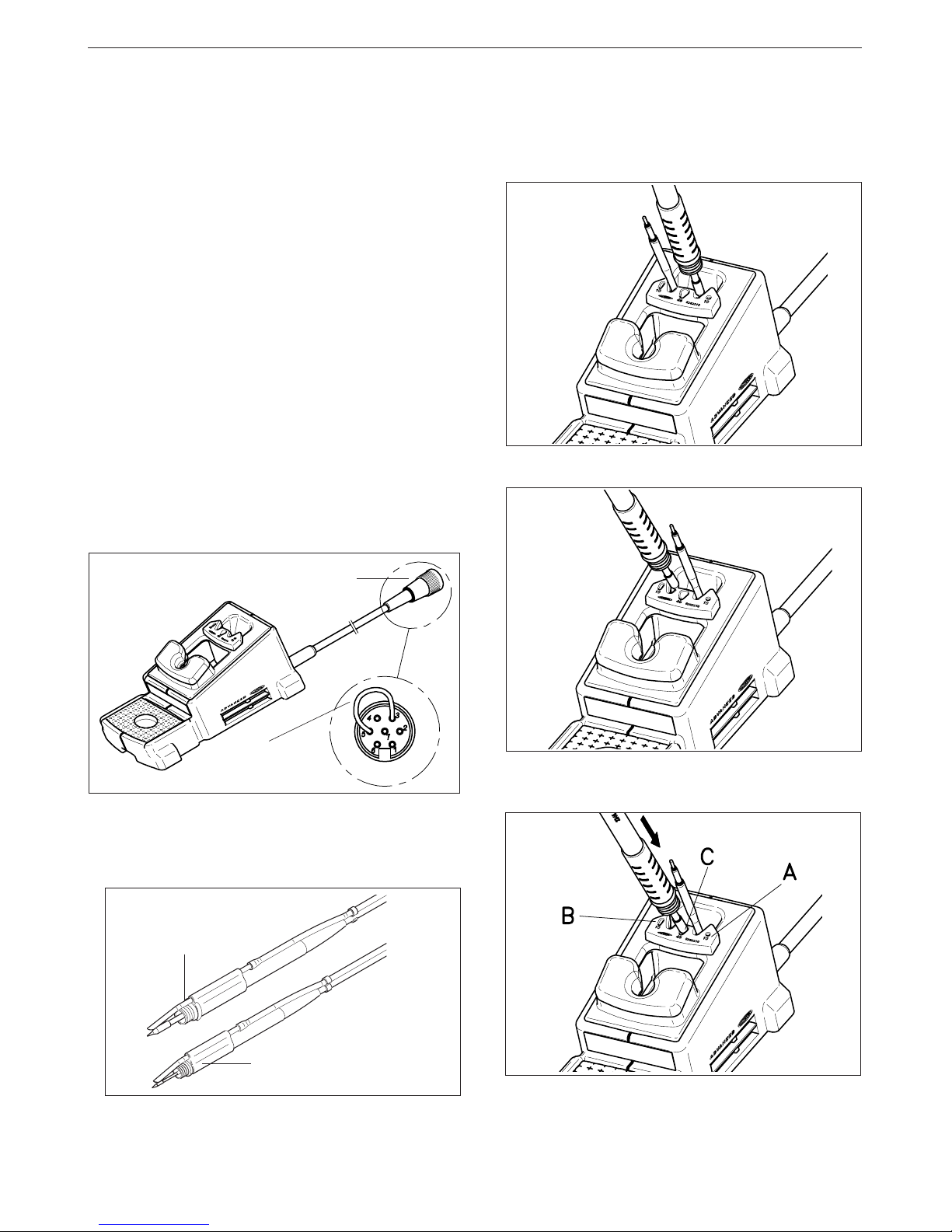
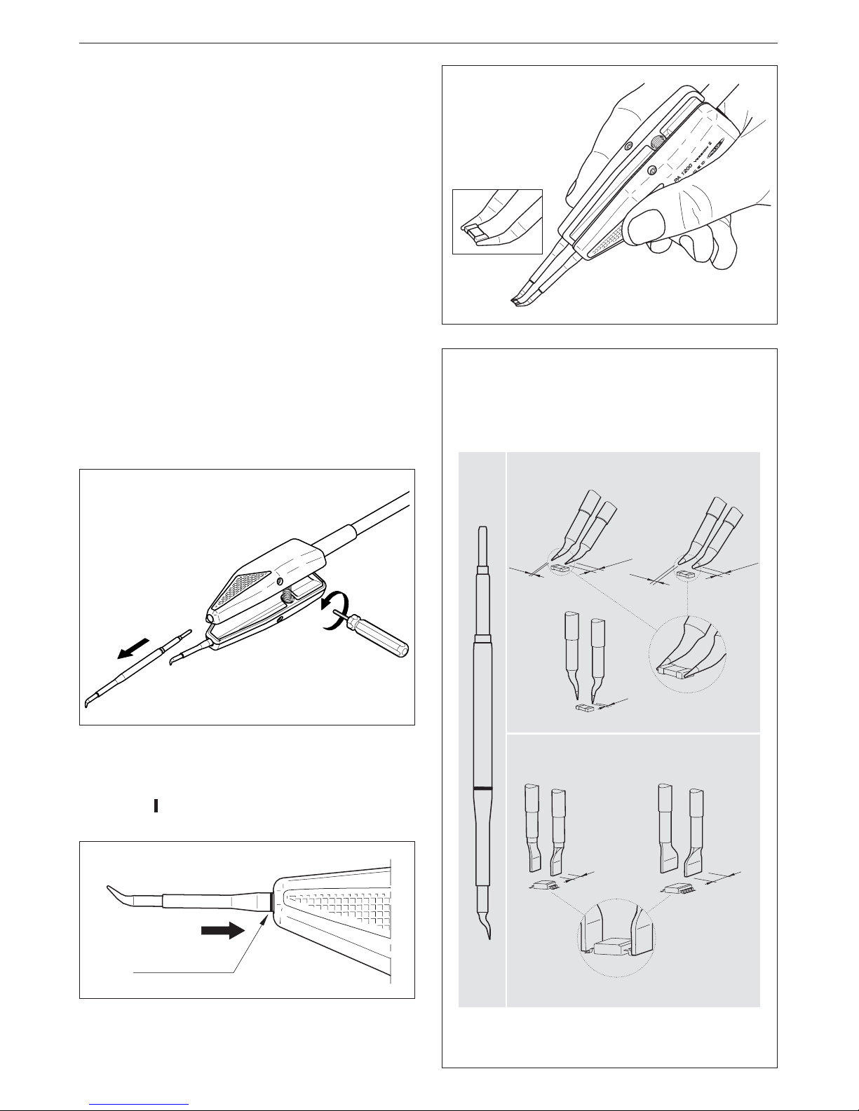
2 - Place the handpiece on top of the new cartridge,
press it slightly down and remove the handpiece.
Changing the handpiece's cartridge
With the Advanced system, the cartridge can be
changed quickly, without turning off the station,
so you have two soldering irons in one. Here is
what to do to change the cartridge:
1 - Place the handpiece and remove the cartridge.
Fume extractor accessories
Specially designed for the Advanced Series
handpieces 2010/2210 and 2045/2245. Easily clips
onto the handpiece and can be quickly removed
for easy maintenance.
For handpieces
2045/2245
0495000
For handpieces
2010/2210
0265000
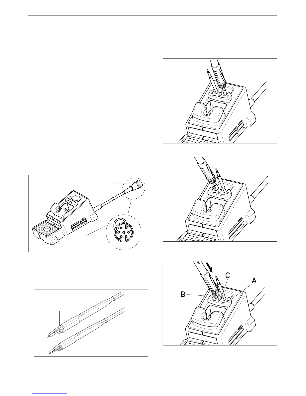
3 - Press the cartridge into the opening A, B or C:
A. For straight cartridges 2010 and 2210.
B. For curved cartridges 2010 and 2210.
C. For cartridges 2045 and 2245.
When connecting an old version solder stand, it may
happen that the sleep function does not work.
To resolve this problem, you should make a bridge
between pins number 3 and 5 from the aerial
connector of the cable of the stand, that plugs in
the station.
Aerial connector
Bridge between
pin number 3 & 5
Page 6
ENGLISH
5
Alignment
XX
XXXXX
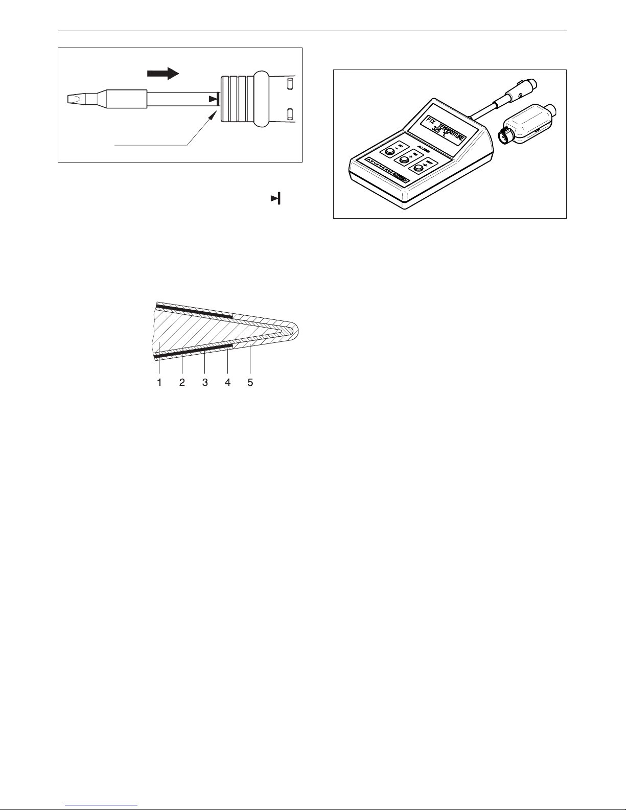
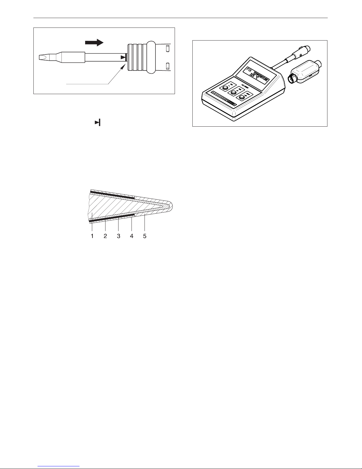
Important.
- It is essential to insert the cartridge till the end
for a good connection. Take the mark a s
reference.
AC 2600
Ref. 2600000
Console AC 2600
The console AC 2600 is designed for modifying the
original regulation program parameters of the following
Advanced control units:
- AD 2000 soldering station.
- AD 2200 soldering station.
- AD 4200 dual soldering station.
- AR 5500 desoldering station.
- AM 6000 rework station.
Changes avalaible to perform:
- Fixing the the working temperature.
- Selection of temperature units in Celsius grades
-°C- or Fahrenheit -°F-.
- Modification of sleep temperatures and standby
times.
- Adjustment of temperature.
- Set the parameters back to the original parameters.
- Read-out data:
Working hours.
Sleep cycles and sleep hours.
Cartridge and iron changes.
Program version.
Advanced series cartridge
Cartridge is made of the heating element which has the
heating system, temperature sensor and long life tip.
Long-life tip is basically made of:
1 Copper
2 Iron
3 Nikel
4 Chromium
5 Tin plate
Long-life tip care
Except the copper core, the rest of metals are placed
galvanically on layers relatively thin, so it is necessary
to avoid the reasons which can cause its destruction.
To clean the tips, use the sponge included with
the stand and check it is lightely moisted.
To re-tin the soldering tips, we recommend using
the tip tinner/cleaner TT 9400 ref. 9400000.
Page 7
ENGLISH
6
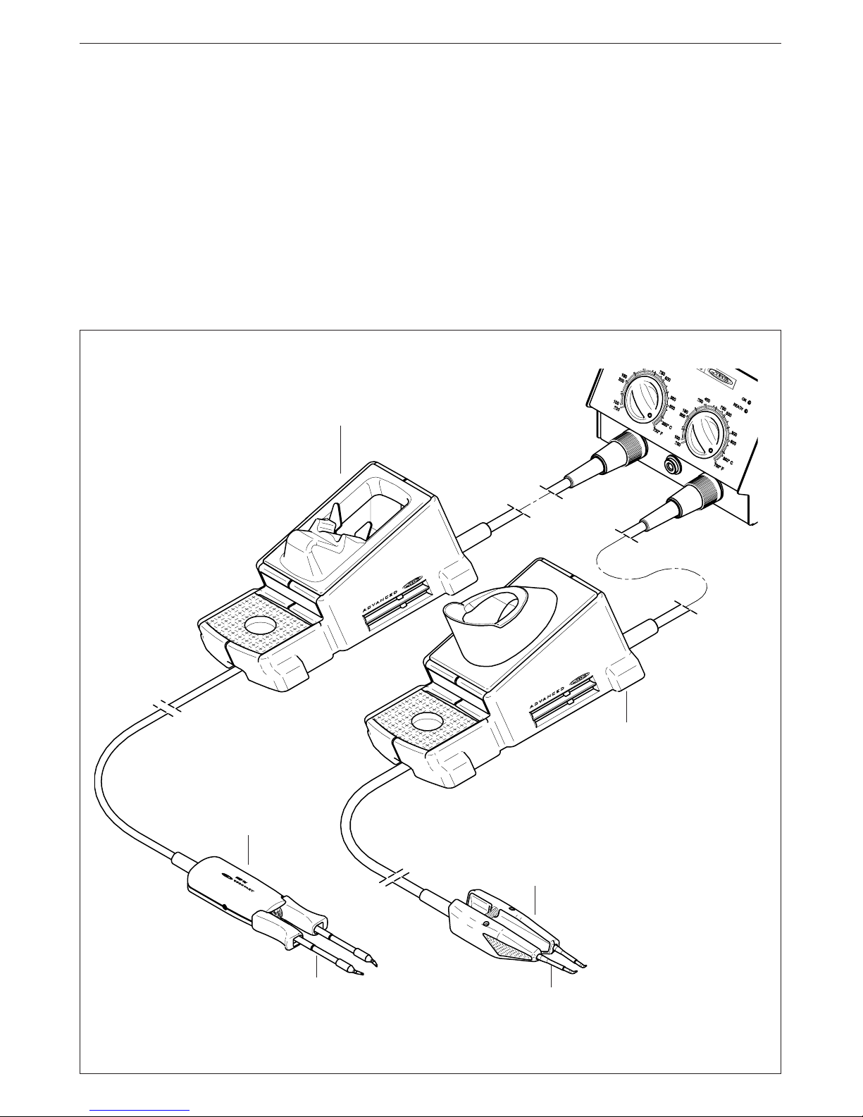
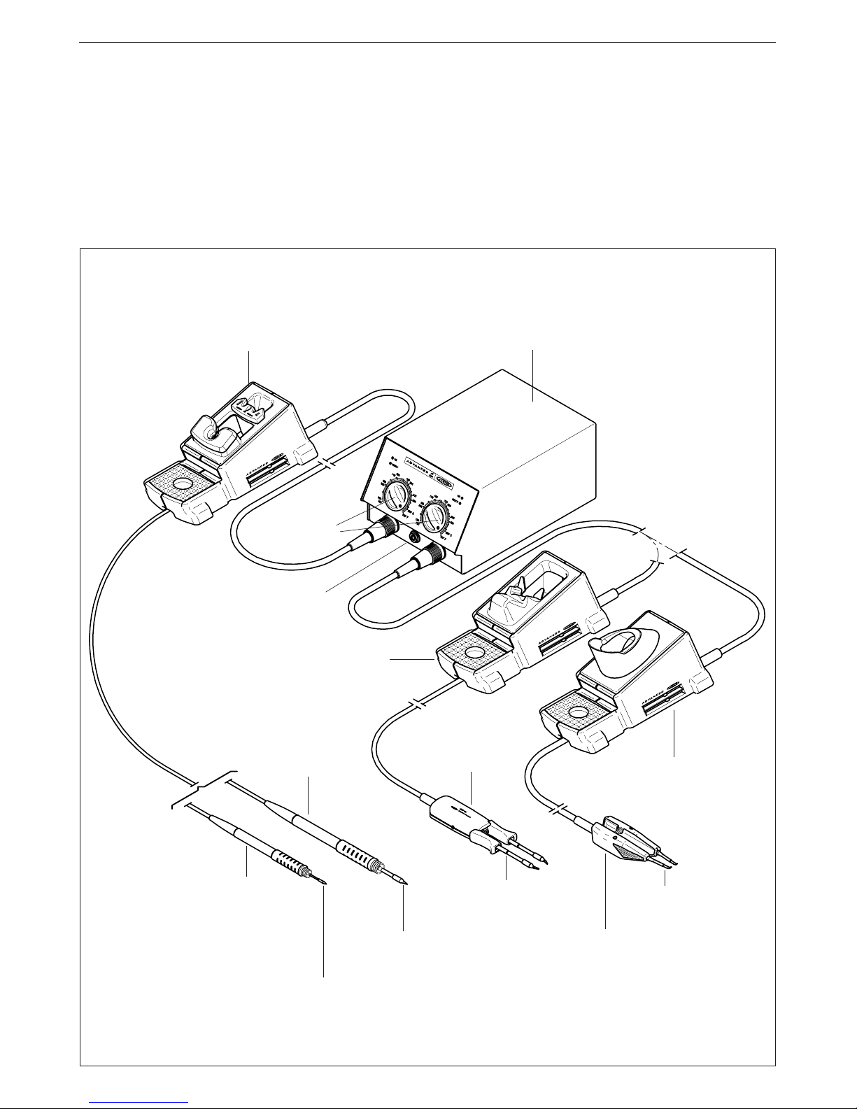
HOT TWEEZERS
AD 4200 station allows to connect two different
models of tweezers, each one with its respective
range of cartridges and stand:
-Micro hot tweezers PA 1200 ref. 1200000.
- Hot tweezers PA 4200 ref. 4200000.
For tweezers to work properly, the following
components are required: control unit, hot tweezers,
a stand and a set of cartridges corresponding to
the chosen tweezer.
Hot tweezers
PA 4200
Ref. 4200000
Cartridges for the hot
tweezers PA 4200
Stand PA 8420
Ref. 0748420
The tweezers are connected to the station in the
following way:
The cable connector of the tweezers is plugged
into the connector of the stand. The cable connector
of the stand is connected to the terminal of the
station. Please find the connection plan on figure.
Cartridges 1200
Micro hot tweezers
PA 1200
Ref. 1200000
Stand PA 8100
Ref. 0748100
(This stand is either for tweezers
PA 1200 and PA 4200)
Page 8

ENGLISH
7
OPERATION
LED lights
Red LED -ON- when lit, it indicates that the station is
plugged in the mains.
Green LED -READY- when lit, it indicates that the
system is ready and correctly set for working.
The green led light is on after a few seconds, is the
time needed to carry on the self-checking system.
The green light is pulsing when the hot tweezers are
in sleep mode.
If the green led is not lit, the reason why, will be one
of the following:
1. The hot tweezers or the cartridge are not
plugged in.
2. The maximum available power has been
exceeded for too long - e.g. in a very thick
soldering at the high repetition rates.
3. The hot tweezers or cartridge has a short circuit
or an open circuit.
4. Any other trouble preventing the system from
working properly.
The hot tweezers will reset itself automatically should
the cartridge short circuit or go open circuit.
Should the hot tweezers be subject to:
- An electrical surge or the cartridge has not been
fitted correctly.
Please turn the unit off and switch on again to reset.
Sleep function
One of the Series Advanced features is that when
the hot tweezers are placed in the holder, the
temperature at the tip drops automatically to the
sleep temperature. This function is only possible
because of the quick response time which does
not make the user realise the temperature rise
to reach the selected temperature. Also by
this, the oxidation of the tinning of the tip is
considerably reduced and tip life is extended.
To indicate that the hot tweezers are in sleepmode, the green led starts pulsing. These
parameters can be modified using the Console
AC 2600 Ref. 2600000.
In order to take advantage of the above
mentioned feature and as a security measure,
it is necessary to place the hot tweezers on
stand when the iron is not being used.
Page 9
ENGLISH
8
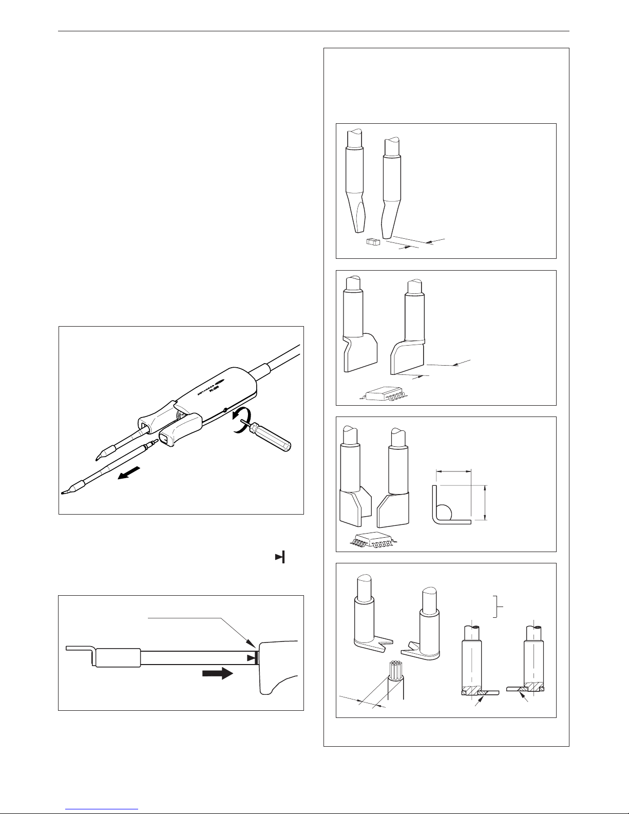
Changing the cartridge
To extract the cartridge the screw needs to be
unfastened and the cartridge pulled out. Insert
the new cartridge and push it thoroughly. Then
check that both tips of the tweezers coincide
and screw it.
Important.
- It is essential to insert the cartridge till
the end for a good connection. Take the
mark as reference and check that both
parts of the tweezer coincide.
Alignment
MICRO HOT TWEEZERS PA 1200
For micro hot tweezers to work properly, the
following components are required:
-Control unit.
-Micro hot tweezers PA 1200 ref. 1200000. For
general precision desoldering with SMD
components.
Power: 40W.
Effective power per cartridge fitted: 20W.
- Stand PA 8100 ref. 0748100.
-A set of cartridges (see range).
RANGE OF CARTRIDGES
PA 1200 has an individual temperature control
for each cartridge so it is supplied individually.
1200
JBC
1200-001
95238
1200-005
5
1200-003
3
1200-001
ø0.2
CHIP COMPONENTS
IC COMPONENTS
1200-002
ø0.2
1.5mm
1200-004
ø0.7
1.5mm
PATENT PENDING
All the cartridges shown are actual size.
Page 10
ENGLISH
9
JBC reserves the right to make technical changes without
prior notification.
HOT TWEEZERS PA 4200
For hot tweezers to work properly, the following
components are required:
-Control unit.
- Hot tweezers PA 4200 ref. 4200000. For general
desoldering and soldering work in professional
electronics.
Power: 100W.
Effective power per cartridge fitted: 50W.
- Stand PA 8420 ref. 0748420 or stand PA 8100
ref. 0748100.
-A set of cartridges (see range).
A
A
A
ØA
A
Ref. A mm
2245-271 1,5
2245-272 2,5
Chip components
Ref. A mm
2245-273 4,0
2245-274 6,0
2245-275 8,0
2245-276 10,0
2245-277 15,0
2245-278 20,0
Dual in line IC
Ref. A mm
2245-279 8,0
2245-280 11,0
QFP and PLCC
Ref. A mm
2245-281
2245-282
Cable stripper
RANGE OF CARTRIDGES
PA 4200 has an individual temperature control
for each cartridge so it is supplied
individually.
2245-281
2245-282
3,5 max
Changing the cartridge
To extract the cartridge the screw needs to be
unfastened and the cartridge pulled out. Insert
the new cartridge and push it thoroughly. Then
check that both tips of the tweezers coincide
and screw it.
Important.
- It is essential to insert the cartridge till the end
for a good connection. Take the mark as
reference and check that both parts of the
tweezer coincide.
Alignment
PATENT PENDING
Page 11
ESPAÑOL
11
Agradecemos la confianza depositada en JBC al adquirir esta estación. Ha sido
fabricada con las más estrictas normas de calidad para prestarle el mejor servicio.
Antes de poner en marcha el aparato, recomendamos leer con atención las
instrucciones que a continuación se detallan.
Usted ha adquirido una Unidad de Control Advanced AD 4200.
Para que la estación soldadora esté completa debe elegir el lápiz o la pinza desoldadora, el soporte y los
cartuchos adecuados al trabajo a realizar. La Unidad de Control es válida sólo para los lápices 2010,
2210, 2045, 2245 y las pinzas desoldadoras PA 1200 o PA 4200 con sus respectivos cartuchos.
Unidad de control
AD 4200 EU Ref. 4200200
AD 4200 UK Ref. 4200201
* Soporte pinza desoldadora
PA 8420
Ref. 0748420
* Pinza desoldadora
PA 4200
Ref. 4200000
* Estos elementos no se
suministran con la unidad
de control
* Cartuchos para
la pinza PA 4200
Selección
temperatura
Borne
equipotencial
Estación soldadora dual
* Soporte soldador
AD 8200
Ref. 0268200
* Lápiz 2010
Ref. 2010000
* Lápiz 2210
Ref. 2210000
* Lápiz 2045
Ref. 2045000
* Lápiz 2245
Ref. 2245000
* Cartuchos 2010
* Cartuchos 2210
* Cartuchos 2045
* Cartuchos 2245
* Micro pinza desoldadora
PA 1200
Ref. 1200000
* Cartuchos 1200
* Soporte pinza desoldadora
PA 8100
Ref. 0748100
Page 12

ESPAÑOL
12
Estructura de la estación soldadora dual
Advanced
Para disponer de la máxima flexibilidad y adaptarse
al trabajo a realizar, está dividida en módulos
básicos, que se suministran por separado.
Unidad de control dual
- AD 4200 EU Ref. 4200200
- AD 4200 UK Ref. 4200201
En esta unidad se pueden conectar
simultáneamente dos herramientas, ya sean lápices
soldadores o pinzas desoldadoras. Las
herramientas que se pueden conectar son: los
lápices soldadores 2010, 2210, 2045 y 2245 y las
pinzas desoldadoras PA 1200 o PA 4200.
Lápices soldadores
- 2010 Ref. 2010000
Potencia: 20W. Para trabajos de precisión, SMD,
etc.
- 2210 Ref. 2210000
Potencia: 20W. Para trabajos de precisión, SMD,
etc.
- 2045 Ref. 2045000
Potencia: 50W. Soldadura en electrónica general.
- 2245 Ref. 2245000
Potencia: 50W. Soldadura en electrónica general.
Pinzas desoldadoras
- PA 1200 Ref. 1200000
Para desoldaduras de precisión con componentes
SMD.
Potencia: 40W .
Potencia efectiva del cartucho: 20W.
- PA 4200 Ref. 4200000
Se utiliza para trabajos generales de desoldadura
y soldadura en electrónica profesional.
Potencia: 100W .
Potencia efectiva del cartucho: 50W.
Cartuchos
- Gama de cartuchos 2010 (para el lápiz 2010).
- Gama de cartuchos 2210 (para el lápiz 2210).
- Gama de cartuchos 2045 (para el lápiz 2045).
- Gama de cartuchos 2245 (para el lápiz 2245).
- Gama de cartuchos para la pinza desoldadora
PA 1200.
- Gama de cartuchos para la pinza desoldadora
PA 4200.
Soportes
- AD 8200 soporte soldador Ref. 0268200
- PA 8420 Ref. 0748420
soporte para la pinza PA 4200.
- PA 8100 Ref. 0748100
soporte para las pinzas PA 1200 y PA 4200.
Unidad de control doble AD 4200
Se sumistra compuesta por:
- Unidad de control.
- Cable de conexión a red.
- Manual de instrucciones.
- Envase de transporte.
Datos técnicos
- Selección de la temperatura entre 100 y 371°C
(±5%).
- Potencia: 135W.
- Transformador de seguridad, separador de red
y doble aislamiento, con fusible integrado de
protección temperatura.
- Entrada: 230V 50Hz. Salida: 24V.
- Protección eléctrica clase I.
- Peso unidad completa: 5Kg.
- Caja antiestática.
Resistencia típica superficial: 105-1011 Ohms/
cuadro.
- Cumple la normativa CE sobre seguridad
eléctrica, compatibilidad electromagnética y
protección antiestática.
- El borne equipotencial y la punta del soldador están
en conexión directa a la toma de tierra de red.
RECOMENDACIONES DE USO
Para soldar y desoldar
- Los componentes y el circuito deben estar
limpios y desengrasados.
- Con preferencia seleccione una temperatura
inferior a 350°C. El exceso de temperatura
puede provocar el desprendimiento de las
pistas del circuito impreso.
- La punta debe estar bien estañada para con-
ducir bien el calor. Si permanece mucho tiempo
en reposo, estáñela de nuevo.
Para tener una estación soldadora doble operativa
como mínimo se necesita: la unidad de control doble,
un lápiz o una pinza desoldadora, el soporte y
cartuchos adecuados a la herramienta que se haya
escogido.
Page 13
ESPAÑOL
13
LAPICES 2010, 2210, 2045 Y 2245
La estación AD 4200 permite conectar los
siguientes lápices soldadores:
-Lápiz 2010 ref. 2010000. Potencia: 20W. Se
utiliza para trabajos de precisión, SMD, etc.
Vea la gama de cartuchos 2010 en la pag. 55.
- Lápiz 2210 ref. 2210000. Potencia: 20W. Se
utiliza para trabajos de precisión, SMD, etc.
Vea la gama de cartuchos 2210 en la pag. 55.
- Lápiz 2045 ref. 2045000. Potencia: 50W. Se
utiliza en trabajos de soldadura en electrónica
general. Vea la gama de cartuchos 2045 en la
pag. 54.
-Lápiz 2245 ref. 2245000. Potencia: 50W. Se
utiliza en trabajos de soldadura en electrónica
general. Vea la gama de cartuchos 2245 en la
pag. 54.
Los lápices y cartuchos 2210 y 2245 cumplen las
especificaciones MIL-SPEC-2000 en cuanto a
diferencia de potencial entre la punta del soldador
y la toma de tierra, que debe ser menor de 2mV.
Para tener el soldador operativo se necesita: la
unidad de control, el soporte soldador, un lápiz y
un cartucho.
El lápiz se conecta a la estación de la siguiente forma:
El cable del lápiz se debe conectar al conector
que existe en el soporte soldador AD 8200 y el
cable del soporte soldador se conecta en el
conector de la estación. Vea el gráfico de
conexionado de la estación en la pag. 11.
FUNCIONAMIENTO
Luces de señalización
Luz roja -ON- encendida indica que la estación está
conectada a tensión de red.
Luz verde -READY- encendida indica que el
sistema está dispuesto y en correctas condiciones
de trabajo.
La luz verde se enciende después de unos pocos
segundos, que es el tiempo necesario para que se
realice el autochecking del sistema.
La luz verde parpadea cuando el soldador está en
reposo.
Si la luz verde está apagada, será debido a alguno de
los siguientes motivos:
1. Que el lápiz con cartucho no está conectado.
2. Que se ha superado la potencia máxima disponible
durante un tiempo excesivo, por ejemplo
soldaduras muy gruesas y repetidas, etc.
3. Que el lápiz con cartucho está en cortocircuito
o circuito abierto.
4. Cualquier otra anomalía que haga funcionar
defectuosamente el sistema.
La luz verde se apaga y el soldador deja de ser
alimentado mientras esté en contacto con el
extractor de cartuchos. Esto sucede cuando el
soldador lleva tres segundos en contacto con el
extractor.
El reset de errores es automático cuando el lápiz o el
cartucho están en cortocircuito o circuito abierto.
El reset de errores no es automático, se debe apagar
y volver a conectar la estación, cuando:
- Existe un error de exceso de aporte de energía.
Lápiz 2045 Ref. 2045000
Lápiz 2245 Ref. 2245000
Lápiz 2010 Ref. 2010000
Lápiz 2210 Ref. 2210000
Cartuchos
Page 14
ESPAÑOL
14
Soldador en reposo
Una de las cualidades de la serie Advanced, es que
cuando el lápiz se coloca en el soporte, la temperatura
baja automáticamente hasta la temperatura de
reposo. Esto es posible, gracias a la rapidez de su
respuesta térmica, que permite pasar de la
temperatura de reposo a la de trabajo sin interrupción.
Con lo cual se consigue una gran reducción en la
oxidación del estañado y aumenta de una forma
muy importante la duración de la punta.
Para indicar que el soldador está en reposo, la luz
verde de la unidad de control se pone a parpadear.
Estos parámetros se pueden modificar con la
Consola AC 2600 Ref. 2600000.
Para beneficiarse de la cualidad anterior y como
medida de seguridad, es necesario colocar el
lápiz en el soporte cuando no se utilice.
2 - Sitúe el lápiz sobre el cartucho a cambiar,
presione ligeramente y retírelo.
Cambio del cartucho del lápiz
El sistema Advanced permite el cambio rápido
del cartucho, sin parar la estación, con lo que
dispondrá de dos soldadores en uno. Para ello
siga el proceso que se indica a continuación.
1 - Coloque el lápiz y extraiga el cartucho.
3 - Presione a fondo el lápiz sobre el orificio A, B
o C:
A. Para cartuchos 2010 y 2210 rectos.
B. Para cartuchos 2010 y 2210 curvados.
C. Para cartuchos 2045 y 2245.
Accesorio aspira-humos
Para los lápices 2010/2210 y 2045/2245. Sujección
por sistema clip, se sustituyen con rapidez para
su mantenimiento.
Para los lápices
2045/2245
0495000
Para los lápices
2010/2210
0265000
Si se conecta un soporte para soldador que
corresponda a versiones anteriores, puede suceder
que no funcione la función reposo.
Para solucionarlo deberá hacer un puente entre los
terminales 3 y 5 del conector aereo del cable del
soporte que se conecta a la estación.
Conector aereo
Puente entre los
terminales 3 y 5
Page 15
ESPAÑOL
15
Importante.
- Es indispensable introducir el cartucho hasta
el fondo, para conseguir una buena conexion.
Utilice la marca como referencia.
Alineación
XX
XXXXX
AC 2600
Ref. 2600000
Consola AC 2600
La consola AC 2600 está diseñada para modificar
los parámetros originales del programa de regulación
de las siguienes estaciones de la gama Advanced:
- Estación soldadora AD 2000.
- Estación soldadora AD 2200.
- Estación soldadora dual AD 4200.
- Estación desoldadora AR 5500.
- Estación de reparación multifunción AM 6000.
Permite:
- Fijar la temperatura.
- Selección de las unidades de temperatura en
grados Celsius -°C- o Fahrenheit -°F-.
- Cambiar la temperatura y el tiempo de sleep.
- Ajustar la temperatura.
- Cambiar los parámetros de la estación a los
preseleccionados en fábrica.
- Leer los contadores de:
Horas de trabajo.
Ciclos y horas de sleep.
Cambios de cartucho.
Versión del programa.
Cartuchos de la serie Advanced
El cartucho está compuesto por el elemento calefactor
que incorpora el sistema de calentamiento y el sensor
de la temperatura y también la punta de larga duración.
La punta de larga duración está compuesta
básicamente por:
1 Cobre
2 Hierro
3 Niquel
4 Cromo
5 Estaño
Conservación de las puntas de larga duración
Salvo el núcleo que es de cobre el resto de metales
está depositado galvanicamente en capas
relativamente finas por lo cual es necesario evitar
las causas que puedan provocar su destrucción.
Para la limpieza de las puntas utilice la esponja del
soporte, que debe estar húmeda pero no empapada
de agua.
Si la punta está muy oxidada recomendamos utilizar
la pasta restañadora de puntas TT 9400 ref. 9400000.
Page 16

ESPAÑOL
16
PINZAS DESOLDADORAS
La estación AD 4200 permite conectar dos
modelos de pinza desoldadora, con sus
respectivas gamas de cartuchos y soporte:
-La micro pinza desoldadora PA 1200 ref.
1200000.
-La pinza desoldadora PA 4200 ref. 4200000.
Para tener una pinza desoldadora operativa se
necesita: la unidad de control, una pinza, el
soporte y un par de cartuchos correspondientes
a la pinza que se haya escogido.
Pinza desoldadora
PA 4200
Ref. 4200000
Cartuchos para la
pinza PA 4200
Soporte pinza desoldadora
PA 8420
Ref. 0748420
La pinza se conecta a la estación de la siguiente
forma:
El cable de la pinza se debe conectar al conector
que existe en el soporte y el cable del soporte
pinza se conecta en el conector de la estación.
Vea el gráfico de conexionado en la figura.
Cartuchos 1200
Micro pinza desoldadora
PA 1200
Ref. 1200000
Soporte pinza desoldadora
PA 8100
Ref. 0748100
(Este soporte sirve para las
pinzas PA 1200 y PA 4200)
Page 17

ESPAÑOL
17
FUNCIONAMIENTO
Luces de señalización
Luz roja -ON- encendida indica que la estación está
conectada a tensión de red.
Luz verde -READY- encendida indica que el
sistema está dispuesto y en correctas condiciones
de trabajo.
La luz verde se enciende después de unos pocos
segundos, que es el tiempo necesario para que se
realice el autochecking del sistema.
La luz verde parpadea cuando la pinza está en
reposo.
Si la luz verde está apagada, será debido a alguno de
los siguientes motivos:
1. Que la pinza desoldadora con cartucho no está
conectada.
2. Que se ha superado la potencia máxima disponible
durante un tiempo excesivo, por ejemplo
soldaduras muy gruesas y repetidas, etc.
3. Que la pinza desoldadora con cartucho está
en cortocircuito o circuito abierto.
4. Cualquier otra anomalía que haga funcionar
defectuosamente el sistema.
El reset de errores es automático cuando la pinza
desoldadora o el cartucho están en cortocircuito o
circuito abierto.
El reset de errores no es automático, se debe apagar
y volver a conectar la estación, cuando:
- Existe un error de exceso de aporte de energía.
Pinza desoldadora en reposo
Una de las cualidades de la serie Advanced, es
que cuando la pinza desoldadora se coloca en el
soporte, la temperatura baja automáticamente hasta
la temperatura de reposo. Esto es posible, gracias
a la rapidez de su respuesta térmica, que permite
pasar de la temperatura de reposo a la de trabajo
sin interrupción. Con lo cual se consigue una gran
reducción en la oxidación del estañado y aumenta
de una forma muy importante la duración de la
punta.
Para indicar que la pinza desoldadora está en
reposo, la luz verde de la unidad de control se
pone a parpadear. Estos parámetros se pueden
modificar con la Consola AC 2600 Ref.
2600000.
Para beneficiarse de la cualidad anterior y como
medida de seguridad, es necesario colocar la
pinza desoldadora en el soporte cuando no se
utilice.
Page 18

ESPAÑOL
18
Cambio del cartucho
Afloje el tornillo de sujección y extraiga el
cartucho. Coloque el nuevo cartucho, presione
a fondo comprobando que coincidan las dos
puntas de la pinza. Apriete de nuevo el tornillo.
Importante.
- Es indispensable introducir el cartucho hasta
el fondo, para conseguir una buena conexión.
Utilice la marca como referencia y
compruebe que coincidan las puntas de la
pinza.
Alineación
MICRO PINZA DESOLDADORA PA 1200
Para tener la micro pinza operativa se necesita:
-La unidad de control.
-La micro pinza desoldadora PA 1200 ref.
1200000. Se utiliza para desoldaduras de
precisión con componentes SMD.
Potencia: 40W.
Potencia efectiva del cartucho: 20W.
- El soporte pinza PA 8100 ref. 0748100.
- Un par de cartuchos de la gama de cartuchos
para la micro pinza PA 1200.
GAMA DE CARTUCHOS
La pinza PA 1200 dispone de un control de
temperatura independiente para cada
cartucho, por ello se suministran
individualmente.
1200
JBC
1200-001
95238
1200-005
5
1200-003
3
1200-001
ø0.2
CHIP COMPONENTS
IC COMPONENTS
1200-002
ø0.2
1.5mm
1200-004
ø0.7
1.5mm
PATENT PENDING
Todos los cartuchos son a tamaño real.
Page 19

ESPAÑOL
19
PINZA DESOLDADORA PA 4200
Para tener la pinza operativa se necesita:
-La unidad de control.
-La pinza desoldadora PA 4200 ref. 4200000.
Se utiliza para trabajos generales de
desoldadura y soldadura en electrónica
profesional.
Potencia: 100W.
Potencia efectiva del cartucho: 50W.
- El soporte pinza PA 8420 ref. 0748420 o el
soporte pinza PA 8100 ref. 0748100.
- Un par de cartuchos de la gama de cartuchos
para la pinza PA 4200.
A
A
A
ØA
A
Ref. A mm
2245-271 1,5
2245-272 2,5
Componentes chips
Ref. A mm
2245-273 4,0
2245-274 6,0
2245-275 8,0
2245-276 10,0
2245-277 15,0
2245-278 20,0
Dual in line IC
Ref. A mm
2245-279 8,0
2245-280 11,0
QFP y PLCC
Ref. A mm
2245-281
2245-282
Pela cables
GAMA DE CARTUCHOS
La pinza PA 4200 dispone de un control de
temperatura independiente para cada
cartucho, por ello se suministran
individualmente.
2245-281
2245-282
3,5 max
Cambio del cartucho
Afloje el tornillo de sujección y extraiga el
cartucho. Coloque el nuevo cartucho, presione
a fondo comprobando que coincidan las dos
puntas de la pinza. Apriete de nuevo el tornillo.
Importante.
- Es indispensable introducir el cartucho hasta
el fondo, para conseguir una buena conexión.
Utilice la marca como referencia y
compruebe que coincidan las puntas de la
pinza.
Alineación
JBC se reserva el derecho de introducir modificaciones
sin previo aviso
PATENT PENDING
Page 20

FRANÇAIS
21
Nous vous remercions de la confiance déposée en JBC à travers l’acquisition de
cette station. Elle est fabriquée dans les plus strictes normes de qualité pour vous
rendre un meilleur service. Avant de mettre l’appareil en marche, nous vous
recommandons de lire attentivement les instructions détaillées ci-après.
Vous venez d’acquérir une unité de contrôle dual Advanced AD 4200.
Pour que la station soit complète, vous devez choisir un crayon et/ou une pince à dessouder, les supports et
cartouches respectifs adécuats pour votre travail à réaliser. L’unité de contrôle ne fonctionne qu’avec les
crayons 2010, 2210, 2045, 2245, les pinces à dessouder PA1200 ou PA 4200 et leurs cartouches respectifs.
Unité de contrôle dual
AD 4200 EU Réf. 4200200
AD 4200 UK Réf. 4200201
* Support pince à dessouder
PA 8420
Réf. 0748420
* Pince à dessouder
PA 4200
Réf. 4200000
* Ces éléments ne sont pas
livrés avec la unité de
contrôle
* Cartouches pour la pince
à dessouder PA 4200
Sélection
température
Connecteur
équipotentiel
Station de soudage dual
* Support fer à souder
AD 8200
Réf. 0268200
* Crayon 2010
Réf. 2010000
* Crayon 2210
Réf. 2210000
* Crayon 2045
Réf. 2045000
* Crayon 2245
Réf. 2245000
* Cartouches 2010
* Cartouches 2210
* Cartouches 2045
* Cartouches 2245
* Micropince à dessouder
PA 1200
Réf. 1200000
* Cartouches 1200
* Support pince à dessouder
PA 8100
Réf. 0748100
Page 21

FRANÇAIS
22
Composition de la station de soudage
dual.
L’AD 4200 est dispose de modules séparés afin
que puissiez bénéfier d’une flexibilité maximale et
ainsi vous adapter à votre application.
Unité de contrôle dual
- AD 4200 EU Réf. 4200200
- AD 4200 UK Réf. 4200201
Il est possible de connecter et de travailler
simultanément avec deux outils, qu’ils soient pinces
ou crayons. Les outils que vous pouvez connecter
sont les suivants : crayons 2010, 2210, 2045, 2245
et les pinces à dessouder PA1200 ou PA 4200.
Fers à souder
- 2010 Réf. 2010000
Puissance: 20W. Pour des travaux de précision,
CMS, etc.
- 2210 Réf. 2210000
Puissance: 20W. Pour des travaux de précision,
CMS, etc.
- 2045 Réf. 2045000
Puissance: 50W. Pour des soudures en
électronique générale.
- 2245 Réf. 2245000
Puissance: 50W. Pour des soudures en
électronique générale.
Pinces à dessouder
- PA 1200 Réf. 1200000
Pour dessoudage de précision avec des
composants CMS.
Puissance: 40W.
Puissance effective de la cartouche: 20W.
- PA 4200 Réf. 4200000
S'utilise pour des travaux généraux de
dessoudage et de soudage en électronique
professionelle.
Puissance: 100W.
Puissance effective de la cartouche: 50W.
Cartouches
- Gamme de cartouches 2010 (pour le crayon 2010).
- Gamme de cartouches 2210 (pour le crayon 2210).
- Gamme de cartouches 2045 (pour le crayon 2045).
- Gamme de cartouches 2245 (pour le crayon 2245).
- Gamme de cartouches pour la pince à dessouder
PA 1200.
- Gamme de cartouches pour la pince à dessouder
PA 4200.
Supports
- AD 8200 support fer à souder Réf. 0268200
- PA 8420 Réf. 0748420
support pour la pince à dessouder PA 4200.
Unité de contrôle dual AD 4200
Elle se compose :
- d'une unité de contrôle
- d'un câble d'alimentation
- d'un manuel d'instructions
- d'un emballage pour le transport.
Données techniques
- Sélection de la température entre 100 et 371°C
(±5%).
- Puissance nominale: 135W.
- Transformateur de sécurité, séparateur du
secteur et double isolement, avec fusible
intégré pour la protection de température.
- Entrée: 230V 50Hz. Sortie: 24V.
- Protection électrique de classe I.
- Poids total de l'unité: 5Kg.
- Boîtier antistatique.
Résistance typique superficielle: 105-1011 Ohms/
carré.
- Conforme aux normes CE portant sur la sécurité
électrique, la compatibilité électromagnétique et
la protection antistatique.
- La prise équipotentielle et la cartouche sont en
connexion directe avec la prise de terre secteur.
RECOMMANDATIONS D'UTILISATION
Pour souder et dessouder
- Les composants et le circuit imprimé doivent
être propres et dégraissés.
- De préférence choisir une température
inférieure à 350°C. L’excès de température
peut provoquer le décollement des pistes
du circuit imprimé.
- La panne doit être bien étamée pour bien
conduire la chaleur. Lorsqu’elle est restée
longtemps au repos, l’étamer à nouveau.
- PA 8100 Réf. 0748100
support pour les pinces à dessouder PA 1200 et
PA 4200.
Pour que la station soit complète, vous devez choisir
un crayon et/ou une pince à dessouder, les supports
et cartouches respectifs.
Page 22

FRANÇAIS
23
CRAYONS 2010, 2210, 2045 ET 2245
Il est possible de connecter les crayon suivants à
la station AD 4200 :
- Le crayon 2010 réf. 2010000. Puissance: 20W.
S’utilise pour des travaux de précision, CMS etc.
Voir la gamme de cartouches 2010 en page 55.
- Le crayon 2210 réf. 2210000. Puissance: 20W.
S’utilise pour des travaux de précision, CMS, etc.
Voir la gamme de cartouches 2210 en page 55.
- Le crayon 2045 réf. 2045000. Puissance: 50W.
S’utilise en travaux de soudage en électronique
générale. Voir la gamme de cartouches 2045 en
page 54.
- Le crayon 2245 réf. 2245000. Puissance: 50W.
S’utilise en travaux de soudage en électronique
générale. Voir la gamme de cartouches 2245 en
page 54.
Les crayons et cartouches 2210 et 2245 sont
conformes à la norme MIL-SPEC-2000 en ce qui
concerne le différentiel de puissance entre
l’extrémité de la cartouche et la prise de terre, soit
inférieure à 2mV.
Pour avoir un fer à souder opérationnel, vous avez
besoin de l’unité de contrôle, du support, d’un
crayon et d’une cartouche.
Le crayon se connecte à la station de la façon
suivante:
Le câble du crayon doit être connecté au connecteur
se trouvant sur le support à souder AD 8200 et le
câble du support à souder doit être connecté au
connecteur de la station. Voir le graphique de
connection de la station en page 21.
Crayon 2045 Réf. 2045000
Crayon 2245 Réf. 2245000
Crayon 2010 Réf. 2010000
Crayon 2210 Réf. 2210000
Cartouches
FONCTIONNEMENT
Voyants de signalisation
Voyant rouge -ON- allumé, il indique que le poste
est branché au secteur.
Voyant vert -READY- allumé, il indique que le
système est en état de fonctionner.
Le voyant vert s’allume au bout de quelques
secondes, correspondant au temps nécessaire
pour réaliser l'auto-vérification du système.
Le voyant vert clignote lorsque le fer à souder se
trouve en mode "sleep".
Si le voyant vert est éteint, cela peut être en raison
de l’un des motifs suivants:
1. Crayon et cartouche ne sont pas connectés.
2. La puissance maximale disponible a été
dépassée pendant trop longtemps. Par
exemple soudures très épaisses et répétées.
3. Le crayon avec la cartouche insérée est en
court-circuit ou en circuit ouvert.
4. Toute autre anomalie qui rend defectueux le
système de fonctionnement.
Le voyant vert s'éteint et le crayon à souder
cesse d'être alimenté lorsqu'il est en contact
avec l'extracteur de cartouches. Ceci se produit
lorsque le fer à souder reste plus de trois secondes
connecté à l’extracteur.
Le reset erreur est automatique lorsque le crayon
ou la cartouche sont en court-circuit ou en circuit
ouvert.
Le reset erreur n’est pas automatique, vous devez
éteindre et connecter à nouveau la station lorsque:
- Il existe une erreur d’excès d’apport d’energie.
Page 23

FRANÇAIS
24
Fer à souder au repos
La fonction "sleep" constitue une des principales
qualités de la série Advanced: lorsque le crayon
repose sur son support, la température descend
automatiquement a la température de repos. Ceci
est possible grâce à la rapidité de son temps de
réponse thermique, qui permet de passer de la
température de repos à la température de travail
quasi-instantanément. Ainsi nous obtenons une
grande réduction de l’oxydation de l’étain et ceci
augmente de façon très importante la durée de
vie de la panne.
Le voyant vert clignote lorsque le fer à dessouder
se trouve en mode "sleep". Ces paramètres peuvent
être modifiés au moyen de la Console AC 2600
Réf. 2600000.
Nous vous recommandons, au regard des
avantages décrits précédemment et à titre de
sécurité, de reposer le fer sur son support quand
il n’est pas utilisé.
Accessoire pour aspiration de fumee
Adaptables aux crayons 2010/2210 et 2045/2245.
Maintien par un système de clips qui se detachent
avec rapidité pour leur entretien.
2 - Placer le crayon au-dessus de la cartouche
à remplacer, la faire entrer avec précaution
jusqu’au fond et la retirer de l’extracteur.
Changement de cartouche
Le système Advanced permet un changement rapide
de cartouche sans interrompre le travail ni mettre la
station hors tension, ceci vous procure le confort de
deux fers en un. Pour ce faire, procéder comme suit:
1 - Positionner le crayon et extraire la cartouche.
Pour les crayons
2045/2245
0495000
Pour les crayons
2010/2210
0265000
3 - Utiliser les orifices A, B ou C comme buttoirs.
A. Pour les cartouches 2010 et 2210 rectilignes.
B. Pour les cartouches 2010 et 2210 courbés.
C. Pour les cartouches 2045 et 2245.
Si on connecte un support appartenant à l'ancienne
version, il se peut que la fonction repos ne marche
pas.
Pour apporter une solution il faudra réaliser un pont
entre les terminaux 3 et 5 du connecteur aérien du
cable du support qui se connecte à la centrale.
Connecteur aérien
Pont entre les
terminaux 3 et 5
Page 24

FRANÇAIS
25
Alignement
XX
XXXXX
Important.
- Il est indispensable de bien introduire la
cartouche jusqu'au fond pour obtenir une bonne
connexion. Utilisez la marque comme
référence.
Console AC 2600
Le console AC 2600 est conçue dans le but de
modifier les paramètres originels du programme
de régulation des unités de contrôle suivantes:
-Station à souder AD 2000 (fabrication
postérieure à mars 1999).
- Station à souder AD 2200.
- Station à souder dual AD 4200.
- Station soudage/dessoudage AR 5500.
- Station multifonction AM 6000.
Elle permet de:
- Fixer la température de travail.
- Selection des unités de température en degrés
Celsius -°C- ou Fahrenheit -°F-.
- Changer la température et le délai d’entrée en
mode "sleep".
- Ajuster la température.
- Changer les paramètres de la station
précédemment calibrés lors de la fabrication.
- Lire les compteurs suivants:
Nombre d’heures de fonctionnement.
Nombre de cycle et durée du mode sleep.
Nombre de changement de cartouches.
Version du programme.
AC 2600
Réf. 2600000
Conseils d'utilisation des cartouches
La cartouche se compose d’un élément chauffant,
d'un thermocouple et d'une panne de longue
dureé. Les métaux qui composent la panne de
longue durée sont les suivants:
1 Cuivre
2 Fer
3 Nickel
4 Chrome
5 Etain
Conservation des pannes de longue durée
A part le noyau composé de cuivre, les autre métaux
sont galvanisés en couches relativement fines, d'oú
la nécessité de ne pas provoquer leur destruction.
Pour le nettoyage des pannes veuillez utiliser
l’éponge du support, qui doit être légèrement
humide.
Si la panne est très oxydée nous recommandons
d’utiliser de la pâte à étamer TT 9400 réf. 9400000.
Page 25

FRANÇAIS
26
PINCES À DESSOUDER
La station AD 4200 permet de connecter deux
modèles de pinces à dessouder, avec leurs
gammes respectives de cartouches et supports:
-La micro pince à dessouder PA 1200 réf.
1200000.
-La pince à dessouder PA 4200 réf. 4200000.
Pour qu'une pince à dessouder soit opérationnelle,
nécessite une unité de contrôle, una pince, un
support pince et une paire de cartouches
correspondant à la pince choisie.
Pince à dessouder
PA 4200
Réf. 4200000
Cartouches pour la pince à
dessouder PA 4200
Support pince à dessouder
PA 8420
Réf. 0748420
La pince se connecte à la station de la manière
suivante:
Le câble de la pince doit être connectè au
connecteur existant sur le support pince et le
câble du support pince doit être connecté au
connecteur de la station. Voir schéma de connection
de la station en la figure.
Cartouches 1200
Micro pince à dessouder
PA 1200
Réf. 1200000
Support pince à dessouder
PA 8100
Réf. 0748100
(Ce support sert pour les
pinces PA 1200 et PA 4200)
Page 26

FRANÇAIS
27
FONCTIONNEMENT
Voyants de signalisation
Voyant rouge -ON- allumé, il indique que le poste
est branché au secteur.
Voyant vert -READY- allumé, il indique que le
système est en état de fonctionner.
Le voyant vert s’allume au bout de quelques
secondes, correspondant au temps nécessaire
pour réaliser l'auto-vérification du système.
Le voyant vert clignote lorsque le pince à dessouder
se trouve en mode "sleep".
Si le voyant vert est éteint, cela peut être en raison
de l’un des motifs suivants:
1. Le pince à dessouder avec la cartouche insérée
ne sont pas correctement connectées.
2. La puissance maximale disponible a été
dépassée pendant trop longtemps. Par
exemple lors de soudures très épaisses et
répétées.
3. Le pince à dessouder avec la cartouche
cartouche insérée est en court circuit ou en
circuit ouvert.
4. Toute autre anomalie qui rend defectueux le
système de fonctionnement.
Le reset erreur est automatique lorsque la pince à
dessouder ou la cartouche sont en court-circuit ou
en circuit ouvert.
Le reset erreur n’est pas automatique, vous devez
éteindre et connecter à nouveau la station lorsque:
- Il existe une erreur d’excès d’apport d’energie.
Pince à dessouder au repos
La fonction "sleep" constitue une des principales
qualités de la série Advanced: lorsque la pince à
dessouder repose sur son support, la température
descend automatiquement a la température de
repos. Ceci est possible grâce à la rapidité de
son temps de récupération thermique, qui permet
de passer de la température de repos à celle de
travail de façon quasi-instantanée. Ainsi nous
obtenons une grande réduction de l’oxydation de
l’étain et ceci augmente de considérablement la
durée de vie de la cartouche.
Le voyant vert clignote lorsque la pince à
dessouder se trouve en mode "sleep". Ces
paramètres peuvent être modifiés au moyen
de la Console AC 2600 Réf. 2600000.
Nous vous recommandons, au regard des
avantages décrits précédemment et à titre de
sécurité, de reposer la pince à dessouder sur
son support quand elle n’est pas utilisée.
Page 27

FRANÇAIS
28
GAMME DE CARTOUCHES
La micro pince à dessouder PA 1200 dispose
d'un contrôle de température indépendent
pour chaque cartouche, c'est pourquoi ces
dernières sont livrées individuellement.
1200
JBC
1200-001
95238
1200-005
5
1200-003
3
1200-001
ø0.2
CHIP COMPONENTS
IC COMPONENTS
1200-002
ø0.2
1.5mm
1200-004
ø0.7
1.5mm
PATENT PENDING
Toutes les cartouches sont de grandeur nature.
Changement de cartouche
Dessérer la vis de maintien et extraire la cartouche.
Mettre en place la nouvelle cartouche appuyer à
fond, en vous assurant que les deux pointes de
la pince coincides. Resserer à nouveaux la vis.
Important.
- Il est indispensable de bien introduire la
cartouche jusqu'au fond pour obtenir une bonne
connexion. Utilisez la marque comme
référence en vous assurant que les deux
pointes de la pince coincides.
Alignement
MICRO PINCE À DESSOUDER PA 1200
Pour que la micro pince soit opérationnelle
nécessite:
-L'unité de contrôle.
-La micro pince à dessouder PA 1200 réf.
1200000. Pour dessoudage de précision avec
des composants CMS.
Puissance: 40W.
Puissance effective de la cartouche: 20W.
-Le support pince PA 8100 réf. 0748100.
-Une paire de cartouches de la gamme de
cartouches pour la micro pince à dessouder PA
1200.
Page 28

FRANÇAIS
29
PINCE À DESSOUDER PA 4200
Pour que la pince à dessouder soit opérationnelle
nécessite:
-L'unité de contrôle.
-La pince à dessouder PA 4200 réf. 4200000.
S’utilise pour des travaux généraux de
dessoudage et de soudage en électronique
professionnelle.
Puissance: 100W.
Puissance effective de la cartouche: 50W.
-Le support pince PA 8420 réf. 0748420 ou le
support pince PA 8100 réf. 0748100.
-Une paire de cartouches de la gama de
cartuchos para la pinza desoldadora PA 4200.
A
A
A
ØA
A
Réf. A mm
2245-271 1,5
2245-272 2,5
Composants chips
Réf. A mm
2245-273 4,0
2245-274 6,0
2245-275 8,0
2245-276 10,0
2245-277 15,0
2245-278 20,0
Pour CI Dual in
line
Réf. A mm
2245-279 8,0
2245-280 11,0
Pour QFP et PLCC
Réf. A mm
2245-281
2245-282
Dénudeur de câbles
GAMME DE CARTOUCHES
La pince à dessouder PA 4200 dispose d'un
contrôle de température indépendent pour
chaque cartouche, c'est pourquoi ces dernières
sont livrées individuellement.
2245-281
2245-282
3,5 max
Changement de cartouche
Dessérer la vis de maintien et extraire la cartouche.
Mettre en place la nouvelle cartouche appuyer à
fond, en vous assurant que les deux pointes de
la pince coincides. Resserer à nouveaux la vis.
Important.
- Il est indispensable de bien introduire la
cartouche jusqu'au fond pour obtenir une bonne
connexion. Utilisez la marque comme
référence en vous assurant que les deux
pointes de la pince coincides.
Alignement
JBC se réserve le droit d'apporter des modifications
techniques à ses appareils sans préavis
PATENT PENDING
Page 29

DEUTSCH
31
Sie haben eine Steuereinheit Advanced AD 4200 erworben.
Damit die Lötstation einsatzbereit wird, müssen Sie die für die zu verrichtenden Arbeiten geeigneten
Handstücke oder Entlötpinzetten, Ständer und Kartuschen auswählen. Die Steuereinheit ist nur für den
Einsatz der Handstücke 2010, 2210, 2045, 2245 sowie der Entlötpinzetten PA 1200 oder PA 4200 mit ihren
jeweiligen Kartuschen vorgesehen.
Wir danken Ihnen für das JBC mit dem Kauf dieser Station erwiesene Vertrauen. Bei
ihrer Fertigung wurden die strengsten Qualitätsmaßstäbe zugrunde gelegt, so dass
Sie optimale Lötergebnisse erwarten dürfen. Vor Inbetriebnahme des Geräts lesen
Sie bitte die vorliegende Betriebsanleitung aufmerksam durch.
Steuereinheit
AD 4200 EU Ref. 4200200
AD 4200 UK Ref. 4200201
* Entlötpinzettenständer
PA 8420
Ref. 0748420
* Entlötpinzette
PA 4200
Ref. 4200000
* Diese Elemente werden nicht
mit der Station geliefert
* Kartuschen für die
Entlötpinzette PA 4200
Temperaturwahl
Potentialausgleichsbuchse
Dual-Lötstation
* Lötkolbenständer
AD 8200
Ref. 0268200
* Handstück 2010
Ref. 2010000
* Handstück 2210
Ref. 2210000
* Handstück 2045
Ref. 2045000
* Handstück 2245
Ref. 2245000
* Kartuschen 2010
* Kartuschen 2210
* Kartuschen 2045
* Kartuschen 2245
* Mikroentlötpinzette
PA 1200
Ref. 1200000
* Kartuschen 1200
* Entlötpinzettenständer
PA 8100
Ref. 0748100
Page 30

DEUTSCH
32
Aufbau der Dual-Lötstation Advanced
Um eine möglichst hohe Flexibilität zu erreichen und
sich an die zu verrichtende Arbeit anzupassen,
besteht sie aus Grundmodulen, die getrennt
lieferbar sind.
Dual-Steuereinheit
- AD 4200 EU Ref. 4200200
- AD 4200 UK Ref. 4200201
An dieser Einheit können gleichzeitig zwei
Werkzeuge - Handstücke oder Entlötpinzetten angeschlossen werden. Die folgenden Werkzeuge
können angeschlossen werden: die Handstücke
2010, 2210, 2045 und 2245 sowie die Entlötpinzetten
PA1200 oder PA 4200.
Handstücke
- 2010 Ref. 2010000
Leistung: 20 W . Zum Einsatz für Präzisionsarbeiten,
SMD usw.
- 2210 Ref. 2210000
Leistung: 20 W . Zum Einsatz für Präzisionsarbeiten,
SMD usw.
- 2045 Ref. 2045000
Leistung: 50 W. Zum Einsatz für allgemeine
Lötarbeiten.
- 2245 Ref. 2245000
Leistung: 50 W. Zum Einsatz für allgemeine
Lötarbeiten.
Entlötpinzetten
- PA 1200 Ref. 1200000
Zum hochpräzisen Entlöten von SMDKomponenten.
Leistung: 40W. Reale Kartuschenleistung: 20W.
- PA 4200 Ref. 4200000
Für allgemeine Löt- und Entlötarbeiten in der
professionellen Elektronik.
Leistung: 100W. Reale Kartuschenleistung: 50W.
Kartuschen
- Kartuschenangebot 2010 (für Handstück 2010).
- Kartuschenangebot 2210 (für Handstück 2210).
- Kartuschenangebot 2045 (für Handstück 2045).
- Kartuschenangebot 2245 (für Handstück 2245).
- Kartuschenangebot für die Entlötpinzette PA 1200.
- Kartuschenangebot für die Entlötpinzette PA 4200.
Ständer
- AD 8200 Lötkolbenständer Ref. 0268200
- PA 8420 Ref. 0748420
Ständer für die Entlötpinzette PA 4200.
- PA 8100 Ref. 0748100
Ständer für die Entlötpinzetten PA 1200 und PA
4200.
Dual-Steuereinheit AD 4200
Im Lieferumfang:
- Steuereinheit.
- Kaltgerätestecker.
- Bedienungsanleitung.
- Transportverpackung.
Technische Daten
- Temperaturwahl zwischen 100 und 371°C
(±5%).
- Leistung: 135 W.
- Netzgetrennter Sicherheitstransformator mit
doppelter Isolierung und integrierter
Brandschutzsicherung.
- Eingangsspannung: 230V 50Hz.
Ausgangsspannung: 24V.
- Elektrische Schutzklasse I.
- Gewicht der kompletten Anlage: 5Kg.
- Astatisches Gehäuse.
Typischer Oberflächenwiderstand:
105-1011 Ohm/Quadrat.
- Erfüllt die EG-Sicherheitsvorschriften über
elektrische Sicherheit, elektromagnetische
Kompatibilität und antistatischen Schutz.
-Die Equipotentialausgleichsbuchse ist mit der
Erdung des Netzsteckers verbunden.
EMPFEHLUNGEN FÜR DEN GEBRAUCH
Zum Löten und Entlöten
- Komponenten und Leiterplatte müssen sauber
und entfettet sein.
- Möglichst immer mit Temperaturen unter
350°C arbeiten. Höhere Temperaturen können
ein Ablösen der Leitungsbahnen zur Folge
haben.
- Damit die Spitze gut die Wärme leitet, muss
sie gut verzinnt sein. Wenn sie lange nicht
benutzt wurde, ist sie erneut zu verzinnen.
Um über eine einsatzbereite Dual-Lötstation zu
verfügen, benötigt man mindestens: eine DualSteuereinheit, ein Handstück oder eine
Entlötpinzette, den Ständer und die für das
ausgewählte Werkzeug geeigneten Kartuschen.
Page 31

DEUTSCH
33
HANDSTÜCKE 2010, 2210, 2045 UND 2245
An die Station AD 4200 können die folgenden
Lötkolben angeschlossen werden:
- Handstück 2010 Ref. 2010000. Leistung: 20 W.
Zum Einsatz für Präzisionsarbeiten, SMD usw.
Verfügbare Kartuschen 2010 siehe S. 55.
- Handstück 2210 Ref. 2210000. Leistung: 20 W.
Zum Einsatz für Präzisionsarbeiten, SMD usw.
Verfügbare Kartuschen 2210 siehe S. 55.
- Handstück 2045 Ref. 2045000. Leistung: 50 W.
Zum Einsatz für allgemeine Lötarbeiten.
Verfügbare Kartuschen 2045 siehe S. 54.
- Handstück 2245 Ref. 2245000. Leistung: 50 W.
Zum Einsatz für allgemeine Lötarbeiten.
Verfügbare Kartuschen 2245 siehe S. 54.
Die Handstücke und Kartuschen 2210 und 2245
erfüllen die Spezifikationen des MIL-SPEC-2000
bezüglich des Spannungsunterschieds zwischen
Lötspitze und Erdung, der geringer als 2mV sein
muss.
Um eine arbeitsfähige Lötstation zu haben, wird
folgendes benötigt: Steuereinheit,
Lötkolbenständer, ein Handstück und eine
Kartusche.
Der Lötkolben wird folgendermassen an die Station
angeschlossen:
Das Anschlusskabel des Handstücks wird in die
Buchse im Lötkolbenhalter AD 8200, und das
Anschlusskabel des Lötkolbenhalters an den
Anschluss der Station angeschlossen. Siehe auch
Anschlusszeichnung der Station auf der Seite 31.
FUNKTIONSWEISE
Leuchtdioden
Rote LED -ON- zeigt, dass die Station an das Netz
angeschlossen ist.
Grüne LED -READY- zeigt an, dass das System
bereit ist und sich in arbeitsfähigem Zustand befindet.
Die Verzögerung beim Zuschalten der grünen LED
ist durch die Selbstüberprüfung bedingt.
Die grüne Diode blinkt, wenn sich der Lötkolben im
Ruhezustand befindet.
Ist die grüne LED erloschen, kann dies an einem der
folgenden Gründe liegen:
1. Das Handstück mit Kartusche ist nicht
angeschlossen.
2. Während eines längeren Zeitraums wurde die
maximale Leistung überschritten, bspw. durch
das wiederholte Löten sehr großer Lötstellen mit
hoher Wärmeableitung.
3. Am Handstück oder an der Kartusche liegt ein
Kurzschluss vor, oder der Schaltkreis ist offen.
4. Es liegt eine andere Störung vor , die ein korr ektes
Funktionieren des Systems verhindert.
Die grüne LED erlischt und die Stromzufuhr zum
Lötkolben wird unterbrochen, wenn Kontakt
zwischen Kartusche und Abziehvorrichtung
besteht. Dies geschieht, wenn der Lötkolben die
Abziehvorrichtung drei Sekunden lang berührt.
Der Fehlerreset erfolgt selbsttätig, wenn an der
Handstück oder Kartusche ein Kurzschluss vorliegt
oder der Schaltkreis unterbrochen ist.
Der Fehlerreset erfolgt nicht selbsttätig, wenn:
- Ein Fehler durch Spannungsüberschuss
entstanden ist.
In diesem Fall ist die Station aus- und wieder
einzuschalten.
Handstück 2045 Ref. 2045000
Handstück 2245 Ref. 2245000
Handstück 2010 Ref. 2010000
Handstück 2210 Ref. 2210000
Kartuschen
Page 32

DEUTSCH
34
Standby-Funktion
Befindet sich das Handstück im Lötkolbenständer,
wird die Temperatur an der Lötspitze automatisch
auf Standby-Temperatur abgesenkt. Das direkte
thermische Ansprechen macht es möglich, ohne
Unterbrechung von der Standby-Temperatur zur
Arbeitstemperatur zu wechseln. Durch die reduzierte
Standby-Temperatur wird eine Reduzierung der
Oxidation der Verzinnung der Spitze und somit
eine längere Lebenszeit der Spitze erreicht.
Um anzuzeigen, dass sich der Lötkolben im
Ruhezustand befindet, pulsiert die grüne Diode.
Diese Parameter können mit der Konsole AC
2600 Ref. 2600000 geändert werden.
Um diesen Vorteil zu nutzen sowie aus
Sicherheitsgründen ist es erforderlich, den
Lötkolben bei Nichtbenutzung im Halter abzulegen.
Zubehör Lötdampfabsauger
Passend für die Handstücke 2010/2210 und 2045/
2245. Sind dank eines Clip-Systems leicht
aufzustecken und zur Wartung schnell austauschbar.
2 - Stecken Sie den Lötkolben auf die Kartusche,
die Sie einsetzen wollen, üben Sie leichten
Druck aus und ziehen Sie ihn dann heraus.
1 - Setzen Sie den Lötkolben ab und ziehen Sie
die Kartusche ab.
Für die Handstücke
2045/2245
0495000
Für die Handstücke
2010/2210
0265000
3 - Drücken Sie den Lötkolben bis zum Anschlag
in die Öffnungen A, B oder C.
A. Für gerade Kartuschen 2010 und 2210.
B. Für gebogene Kartuschen 2010 und 2210.
C. Für Kartuschen 2045 und 2245.
Auswechseln der Kartusche
Das System Advanced erlaubt ein schnelles und
problemloses Auswechseln der Kartuschen bei
eingeschalteter Station, so dass Sie praktisch
zwei Lötkolben in einem haben. Dabei ist
folgendermaßen vorzugehen:
Wenn eine ältere Version eines Lötkolbenständers
angeschlossen wird, kann die Standby-Funktion
möglicherweise nicht funktionieren.
Um dieses Problem zu beseitigen, überbrücken Sie
die Buchsen 3 und 5 des Steckers des
Ständerkabels, das an der Station angeschlossen
ist.
Steckanschluss
Buchsen 3 und 5
überbrückt
Page 33

DEUTSCH
35
AC 2600
Ref. 2600000
Konsole AC 2600
Die Konsole AC 2600 wurde dazu entwickelt, um die
Ausgangsparameter des Steuerprogramms der
folgenden Advanced-Stationen zu verändern:
- Lötstation AD 2000.
- Lötstation AD 2200.
- Dual-Lötstation AD 4200.
- Entlötstation AR 5500.
- Multifunktions-Reparaturstation AM 6000.
Ermöglicht:
-Temperatur festlegen.
- Auswahl der Temperatureinheiten in Grad Celsius
-°C- oder Fahrenheit -°F-.
-Temperatur und Zeit für Stand-By änder n.
-Temperatur justieren.
-Werksseitige Ausgangsparameter wieder
aufrufen.
- Ablesen des Zählerstands der:
Arbeitsstunden.
Ruhezyklen und Ruhestunden.
Kartuschenwechsel.
Programmversion.
Ausrichtung
XX
XXXXX
Wichtig.
- Für eine gute Verbindung ist es
ausschlaggebend, die Kartusche bis zum
Anschlag einzustecken. Orientieren Sie sich
dabei an der Markierung.
Kartuschen der Serie Advanced
Die Kartusche besteht aus dem Heizelement,
welches das Heizsystem und den
Temperatursensor enthält, sowie der long-life Spitze.
Die long-life Spitze ist grundsätzlich aus folgenden
Elementen zusammengesetzt:
1 Kupfer
2 Eisen
3 Nickel
4 Chrom
5 Zinn
Behandlung der long-life Spitzen
Abgesehen vom Kupferkern sind die Metalle
galvanisch in einer dünnen Schicht aufgebracht,
weshalb Beschädigungen vermieden werden müssen.
Zur Reinigung der Spitzen ist der Schwamm zu
benutzen, der leicht mit Wasser angefeuchtet sein
sollte.
Wenn die Spitze stark oxidiert ist, empfehlen wir
einen der von verschiedenen Herstellern
angebotenen Spitzenverzinner zu verwenden. Wenn
die Spitze sehr stark oxidiert ist, empfehlen wir die
Spitzenverzinnpaste TT 9400 Ref. 9400000.
Page 34

DEUTSCH
36
ENTLÖTPINZETTEN
An die Station AD 4200 können zwei verschiedene
Entlötpinzetten mit ihren dazugehörigen
Kartuschen und Ständern angeschlossen werden:
- Die Mikroentlötpinzette PA 1200 Ref. 1200000.
- Entlötpinzette PA 4200 Ref. 4200000.
Um mit der Entlötpinzette arbeiten zu können,
benötigt man: eine Steuereinheit, eine
Entlötpinzette, einen Ständer und einige
Kartuschen für die ausgewählte Entlötpinzette.
Entlötpinzette
PA 4200
Ref. 4200000
Kartuschen für die
Entlötpinzette PA 4200
Entlötpinzettenständer
PA 8420
Ref. 0748420
Die Pinzette wird folgendermaßen an die Station
angeschlossen:
Das Anschlusskabel der Pinzette wird in die Buchse
im Entlötpinzettenständer angeschlossen. Das
Anschlusskabel des Entlötpinzettenständer wird
an den Anschluss der Station angeschlossen.
Siehe die Anschluss-Skizze auf der Abbildung.
Kartuschen 1200
Mikroentlötpinzette
PA 1200
Ref. 1200000
Entlötpinzettenständer
PA 8100
Ref. 0748100
(Dieser Ständer eignet sich sowohl für die
Entlötpinzette PA 1200 als auch PA 4200)
Page 35

DEUTSCH
37
FUNKTIONSWEISE
Leuchtdioden
Rote LED -ON- zeigt, dass die Station mit der
Netzspannung verbunden ist.
Grüne LED -READY- zeigt an, dass das System
bereit ist und sich in arbeitsfähigem Zustand
befindet.
Die Verzögerung beim Zuschalten der grünen LED
ist durch die Selbstüberprüfung bedingt.
Die grüne Diode blinkt, wenn sich die Entlötpinzette
im Ruhezustand befindet.
Ist das grüne LED erloschen, kann dies an einem der
folgenden Gründe liegen:
1. Das Entlötpinzette mit Kartusche ist nicht
angeschlossen.
2. Während eines längeren Zeitraums wurde die
maximale Leistung überschritten, bspw. durch
das wiederholte Löten sehr großer Lötstellen mit
hoher Wärmeableitung.
3. An der Entlötpinzette oder an der Kartusche
liegt ein Kurzschluss vor, oder der Schaltkreis
ist offen.
4. Es liegt eine andere Störung vor, die ein korrektes
Funktionieren des Systems verhindert.
Der Fehlerreset erfolgt selbsttätig, wenn an der
Entlötpinzette oder Kartusche ein Kurzschluss
vorliegt oder der Schaltkreis unterbrochen ist.
Der Fehlerreset erfolgt nicht selbsttätig, wenn:
- Ein Fehler durch Spannungsüberschuss
entstanden ist.
In diesem Fall ist die Station aus- und wieder
einzuschalten.
Standby-Funktion
Befindet sich die Entlötpinzette im
Entlötpinzettenständer, wird die Temperatur an
der Entlötspitze automatisch auf StandbyTemperatur abgesenkt. Das direkte thermische
Ansprechen macht es möglich, ohne
Unterbrechung von der Standby-Temperatur zur
Arbeitstemperatur zu wechseln. Durch die
reduzierte Standby-Temperatur wird eine
Reduzierung der Oxidation der Verzinnung der
Spitze und somit eine längere Lebenszeit der
Spitze erreicht.
Um anzuzeigen, dass sich die Entlötpinzette im
Ruhezustand befindet, blinkt die grüne Diode.
Diese Parameter können mit der Konsole AC
2600 Ref. 2600000 geändert werden.
Um diesen Vorteil zu nutzen sowie aus
Sicherheitsgründen ist es erforderlich, die
Entlötpinzette bei Nichtbenutzung im Halter
abzulegen.
Page 36

DEUTSCH
38
Kartuschenwechsel
Lösen Sie die Feststellschraube und ziehen Sie
die Kartusche heraus. Setzen Sie die neue
Kartusche ein, drücken Sie sie bis zum Anschlag
an, wobei Sie darauf achten, dass die beiden
Pinzettenspitzen übereinstimmen. Dann ziehen
Sie die Schraube wieder an.
Wichtig.
- Für eine gute Verbindung ist es
ausschlaggebend, die Kartusche bis zum
Anschlag einzustecken. Orientieren Sie sich
dabei an der Markierung und achten Sie
darauf, dass die Pinzettenspitzen
übereinstimmen.
Ausrichtung
MIKROENTLÖTPINZETTE PA 1200
Um mit der Mikroentlötpinzette arbeiten zu
können, benötigt man:
- Steuereinheit.
- Die Mikroentlötpinzette PA 1200 Ref. 1200000.
Zum hochpräzisen Entlöten von SMDKomponenten.
Leistung: 40W.
Reale Kartuschenleistung: 20W.
- Entlötpinzettenständer PA 8100 Ref. 0748100.
- Einige Kartuschen aus dem Kartuschenangebot
für die Mikroentlötpinzette PA 1200.
KARTUSCHENANGEBO T
Die Mikroentlötpinzette PA 1200 verfügt über
eine unabhängige Temperaturregelung für jede
Kartusche, deshalb werden sie einzeln
ausgeliefert.
1200
JBC
1200-001
95238
1200-005
5
1200-003
3
1200-001
ø0.2
CHIP COMPONENTS
IC COMPONENTS
1200-002
ø0.2
1.5mm
1200-004
ø0.7
1.5mm
PATENT PENDING
Alle Kartuschen sind in Originalgröße
abgebildet.
Page 37

DEUTSCH
39
JBC behält sich das Recht vor, technische oder konstruktive
Änderungen ohne vorherige Ankündigung vorzunehmen
ENTLÖTPINZETTE PA 4200
Um eine arbeitsfähige Entlötpinzette zu haben,
wird folgendes benötigt:
- Steuereinheit.
- Entlötpinzette PA 4200 Ref. 4200000. Für
allgemeine Löt- und Entlötarbeiten in der
professionellen Elektronik.
Leistung: 100 W.
Reale Kartuschenleistung: 50 W.
- Entlötpinzettenständer PA 8420 Ref. 0748420
oder Entlötpinzettenständer PA 8100 Ref.
0748100.
- Einige Kartuschen aus dem Kartuschenangebot
für die Entlötpinzette PA 4200.
A
A
A
ØA
A
Ref. A mm
2245-271 1,5
2245-272 2,5
Chip-Bauteile
Ref. A mm
2245-273 4,0
2245-274 6,0
2245-275 8,0
2245-276 10,0
2245-277 15,0
2245-278 20,0
Für Lineare,
Duale IC
Ref. A mm
2245-279 8,0
2245-280 11,0
Für QFP und PLCC
Ref. A mm
2245-281
2245-282
Kabelabisolierer
KARTUSCHENANGEBOT
Die Kartuschen PA 4200 wer den für die Pinzette
paarweise geliefert. Um eine genaue T emperatur
zu erhalten, müssen zwei verschiedene
Kartuschenmodelle kombiniert werden.
2245-281
2245-282
3,5 max
Kartuschenwechsel
Lösen Sie die Feststellschraube und ziehen Sie
die Kartusche heraus. Setzen Sie die neue
Kartusche ein, drücken Sie sie bis zum Anschlag
an, wobei Sie darauf achten, dass die beiden
Pinzettenspitzen übereinstimmen. Dann ziehen
Sie die Schraube wieder an.
Wichtig.
- Für eine gute Verbindung ist es
ausschlaggebend, die Kartusche bis zum
Anschlag einzustecken. Orientieren Sie sich
dabei an der Markierung und achten Sie
darauf, dass die Pinzettenspitzen
übereinstimmen.
Ausrichtung
PATENT PENDING
Page 38

ITALIANO
41
Lei ha acquistato una Unità di Controllo Advanced AD 4200.
Per avere la stazione saldante completa si deve scegliere lo stilo o la pinza dissaldante, il supporto e le
cartucce adeguate al lavoro da realizzare. L'Unità di Controllo è valida solo per gli stili 2010, 2210, 2045,
2245 e le pinze dissaldanti PA 1200 o PA 4200 e loro rispettive cartucce.
La ringraziamo per la fiducia che ha riposto nella JBC con l’acquisto di questa
stazione. Essa è stata fabbricata secondo le più rigide norme di qualità, per offrirLe
il servizio migliore. Prima di accendere l’apparecchio, Le consigliamo di leggere
attentamente le istruzioni che seguono.
Unità di controllo
AD 4200 EU Rif. 4200200
AD 4200 UK Rif. 4200201
* Supporto pinza dissaldante
PA 8420
Rif. 0748420
* Pinza dissaldante
PA 4200
Rif. 4200000
* Questi elementi non sono
in dotazione con la unità di
controllo
* Cartucce per la pinza
dissaldante PA 4200
Selezione
della temperatura
Connettore
equipotenziale
Stazione saldante dual
* Supporto saldatore
AD 8200
Rif. 0268200
* Stilo 2010
Rif. 2010000
* Stilo 2210
Rif. 2210000
* Stilo 2045
Rif. 2045000
* Stilo 2245
Rif. 2245000
* Cartucce 2010
* Cartucce 2210
* Cartucce 2045
* Cartucce 2245
* Micro pinza dissaldante
PA 1200
Rif. 1200000
* Cartucce 1200
* Supporto pinza dissaldante
PA 8100
Rif. 0748100
Page 39

ITALIANO
42
Struttura della stazione saldante dual
Advanced
Per avere la massima flessibilità nella scelta degli
elementi necessari e per adattarsi al meglio al lavoro
da realizzare, è strutturatta in moduli base che sono
forniti separatamente.
Unità di controllo dual
- AD 4200 EU Rif. 4200200
- AD 4200 UK Rif. 4200201
In questa unità si possono connettare
simultaneamente due utensili, siano essi stili
saldanti o pinze dissaldanti. Gli utensili che si
possono connettare sono: gli stili saldanti 2010,
2210, 2045 e 2245 e le pinze dissaldanti PA 1200
o PA 4200.
Stilo saldante
- 2010 Rif. 2010000
Potenza: 20W. Si usa per lavori di precisione,
SMD, etc.
- 2210 Rif. 2210000
Potenza: 20W. Si usa per lavori di precisione, SMD,
etc.
- 2045 Rif. 2045000
Potenza: 50W. Per lavori generali di saldatura in
elettronica professionale.
- 2245 Rif. 2245000
Potenza: 50W. Per lavori generali di saldatura in
elettronica professionale.
Pinze dissaldanti
- PA 1200 Rif. 1200000
Per dissaldature di precisione con componenti
SMD.
Potenza: 40W.
Potenza effettiva cartuccia: 20W.
- PA 4200 Rif. 4200000
Per lavori generali di dissaldatura e saldatura in
elettronica professionale.
Potenza: 100W.
Potenza effettiva cartuccia: 50W.
Cartucce
- Gamma di cartucce 2010 (per lo stilo 2010).
- Gamma di cartucce 2210 (per lo stilo 2210).
- Gamma di cartucce 2045 (per lo stilo 2045).
- Gamma di cartucce 2245 (per lo stilo 2245).
- Gamma di cartucce per la pinza dissaldante
PA 1200.
- Gamma di cartucce per la pinza dissaldante
PA 4200.
Unità di controllo dual AD 4200
La stazione viene fornita con:
-Unità di controllo.
- Cavo di connessione a rete.
-Manuali d'istruzione.
-Imballaggio.
Dati tecnici
- Selezione della temperatura tra 100 e 371°C
(±5%).
- Potenza: 135W.
- Transformatore di sicurezza, separatore di rete
a doppio isolamento, con fusibile integrato di
protezionne della temperatura.
- Entrata: 230V 50Hz. Uscita: 24V.
- Isolamento elettrico classe I.
- Peso unità: 5Kg.
- Unità di controllo antistatica.
Resistenza tipica superficiale: 105-1011 Ohms/
quadro.
- Assolve la normativa CE riguardante la
sicurezza elettrica, compatibilita'
elettromagnetica e protezione antistatica.
- Il connettore equipotenziale è collegato alla presa
di terra della spina.
CONSIGLI PER L’USO
Per saldare e dissaldare
-I componenti ed il circuito devono essere
puliti e sgrassati.
- Selezionare preferibilmente una temperatura
inferiore a 350°C. Una temperatura eccessiva
può causare il distacco delle piste del circuito
stampato.
- La punta deve essere ben stagnata per
condurre bene il calore. Quando rimane molto
tempo a riposo, stagnarla di nuovo.
Sopporti
- AD 8200 supporto saldatore Rif. 0268200
- PA 8420 Rif. 0748420
supporto pinza dissaldante PA 4200.
- PA 8100 Rif. 0748100
supporto pinze dissaldanti PA 1200 e PA 4200.
Per avere una stazione saldante dual operativa
minima è necessario: l'unità di controllo dual, uno
stilo o una pinza dissaldante, il supporto e le
cartucce adeguate all’utensile scelto.
Page 40

ITALIANO
43
STILI 2010, 2210, 2045 E 2245
La stazione AD 4200 consente connettare i
seguenti stili saldanti:
-Lo stilo 2010 rif. 2010000. Potenza: 20W. Si usa
per lavori di precisione, SMD, etc. Vedere la
gamma di cartucce 2010 alla pag. 55.
-Lo stilo 2210 rif. 2210000. Potenza: 20W. Si usa
per lavori di precisione, SMD, etc. Vedere la
gamma di cartucce 2210 alla pag. 55.
- Lo stilo 2045 rif. 2045000. Potenza: 50W. Per
lavori generali di saldatura in elettronica
professionale. Vedere la gamma di cartucce
2045 alla pag. 54.
- Lo stilo 2245 rif. 2245000. Potenza: 50W. Per
lavori generali di saldatura in elettronica
professionale. Vedere la gamma di cartucce
2245 alla pag. 54.
Gli stili e le cartucce 2210 e 2245 assolvono le
normative MIL-SPEC-2000 in quanto la differenza
di potenziale tra la punta del saldatore e la presa
di terra, è meno di 2mV.
Per avere il saldatore operativo necessita: l'unità
di controllo, il supporto del saldatore, uno stilo e
una cartuccia.
Lo stilo si collega alla stazione nel seguente modo:
Il cavo dello stilo si deve collegare al connettore
sotto il supporto del saldatore AD 8200 e il cavo
del supporto del saldatore si deve collegare al
connettore della stazione. Vedere a pag. 41 il
grafico delle connessioni della stazione.
FUNZIONAMENTO
Led di segnalazione
Led rosso -ON- acceso indica che la stazione è
collegata alla rete elettrica.
Led verde -READY- acceso indica che il sistema è
pronto ed in corrette condizioni di lavoro.
La luce verde si accende dopo qualche secondo, il
tempo necessario per fare autochecking del sistema.
La luce verde lampeggia quando il saldatore è a
riposo.
Se la luce verde è spenta, sarà dovuto a qualcuno dei
seguenti motivi:
1. Che lo stilo o la cartuccia non sono collegati.
2. Che si è superata la massima potenza
disponibile durante un tempo eccessivo, ad
esempio effettuando saldature molto spesse
con una frequenza molto alta.
3. Che lo stilo o la cartuccia sono in cortocircuito
o che il circuito è aperto.
4. Che ci sia qualche anomalia che faccia
funzionare il sistema in modo difettoso.
La luce verde si spegne ed il saldatore cessa di
essere alimentato quando è a contatto con
l'estrattore delle cartucce. Questo succede quando
il saldatore rimane per tre secondi in contatto con
l'estrattore.
Il reset di errori è automatico quando lo stilo o la
cartuccia sono in cortocircuito o che il circuito è
aperto.
Il reset di errori non è automatico (si deve spegnere
e riaccendere la stazione) quando:
- Esiste un errore per richiesta eccessiva d’energia.
Stilo 2045 Rif. 2045000
Stilo 2245 Rif. 2245000
Stilo 2010 Rif. 2010000
Stilo 2210 Rif. 2210000
Cartucce
Page 41

ITALIANO
44
Saldatore a riposo
Una delle qualità della serie Advanced é
l’abbassamento della temperatura dello stilo quando
si pone nel supporto, si abbassa fino alla
temperatura di riposo. Questo fa si che grazie alla
sua rapidità di risposta termica passi dalla
temperatura di riposo alla temperatura di lavoro
senza interruzione. Ne consegue una grande
riduzione della ossidazione della punta ed un
notevole aumento della durata.
Per indicare che il saldatore è in riposo, la luce verde
dell'unità di controllo lampeggerà. Questi parametri
sono modificabilli con la Consolle AC 2600 Rif.
2600000.
Per beneficiare delle qualità precedenti e come
misura di sicurezza, è necessario riporre lo
stilo nel supporto quando non si utilizza.
Accessorio aspira-fumo
Adattabile agli stili 2010/2210 e 2045/2245. Si
inseriscono facilmente con sistema di clip e si
possono sostituire con estrema velocità.
2 - Porre il manico dello stilo sopra la cartuccia
nova, pressare leggermente e ritirarlo.
Cambio della cartuccia dello stilo
Il sistema Advanced permette il cambio rapido
della cartuccia, senza dover spegnere la stazione,
in modo da disporre di due saldatori in uno. Per
realizzare questa operazione, seguire il
procedimento indicato qui di seguito.
1 - Collocare lo stilo ed estrarre la cartuccia.
Per gli stili
2045/2245
0495000
Per gli stili
2010/2210
0265000
3 - Pressare a fondo lo stilo sopra l'orifizio A, B o C:
A. Per cartucce 2010 e 2210 rette.
B. Per cartucce 2010 e 2210 curve.
C. Per cartucce 2045 e 2245.
Se si connette un supporto per saldatore della
versione precedente, può non funzionare la
funzione riposo.
Per risolvere il problema dovrà fare un ponte tra
i terminali 3 e 5 del connettore aereo del cavo
del supporto che si collega alla stazione.
Connetore aereo
Ponte tra i
terminali 3 e 5
Page 42

ITALIANO
45
Consolle AC 2600
La consolle AC 2600 è stata progettata per poter
modificare i parametri originali del programma di
regolazione delle seguenti stazioni delle gamma
Advanced:
- Stazione saldante AD 2000.
- Stazione saldante AD 2200.
- Stazione saldante dual AD 4200.
- Stazione dissaldante AR 5500.
- Stazione di riparazione multifunzione AM 6000.
Consente:
- Fissare la temperatura.
- Selezioni delle unità di misura delle temperature
in gradi Celsius -°C- o Fahrenheit -°F-.
- Cambiare la temperatura ed il tempo di sleep.
-Tarare la temperatura.
-Cambiare i parametri della stazione prestabiliti in
origine.
- Leggere i contatori di:
Ore di lavoro.
Cicli e ore di sleep.
Cambi di cartucce.
Versione del programma.
AC 2600
Rif. 2600000
Allineamento
XX
XXXXX
Importante.
-E'indispensabile inserire la cartuccia fino in
fondo per avere una perfetta connessione.
Utilizzare il segno di allineamento come
riferimento.
Cartucce della serie Advanced
La cartuccia è composta dall’elemento riscaldante
che incorpora il sistema di riscaldamento e il sensore
della temperatura insieme alla punta di lunga durata.
La punta Lunga durata é composta di base da:
1 Rame
2 Ferro
3 Nichel
4 Cromo
5 Stagno
Conservazione delle punte di lunga durata
Escluso il nucleo che è di rame, il resto dei metalli è
depositato galvanicamente in cappe relativamente
sottili, percio é necessario evitare la cause che
possano provocare la sua distruzione.
Per la pulizia delle punte utilizzare la spugnetta,
umida non molto bagnata, incorporata nel supporto.
Quando la punta è molto ossidata raccomandiamo
utilizzare pasta per il ripristino dello stagno TT 9400
rif. 9400000.
Page 43

ITALIANO
46
PINZE DISSALDANTI
La stazione AD 4200 permette di connettare due
modelli di pinze dissaldanti, con le rispettive
gamme di cartucce e supporti:
-La micro pinza dissaldante PA 1200 rif.
1200000.
-La pinza dissaldante PA 4200 rif. 4200000.
Per avere una pinza dissaldante operativa è
necessario: l'unità di controllo, una pinza, il
supporto e un paio di cartucce corrispondenti
alla pinza prescelta.
Pinza dissaldante
PA 4200
Rif. 4200000
Cartucce per la pinza
dissaldante PA 4200
Supporto pinza dissaldante
PA 8420
Rif. 0748420
La pinza si collega alla stazione nel seguente modo:
Il cavo della pinza si deve collegare al connettore
sotto il supporto della pinza e il cavo del supporto
della pinza si deve collegare al connettore della
stazione. Vedere il grafico delle connessioni nella
figura.
Cartucce 1200
Micro pinza dissaldante
PA 1200
Rif. 1200000
Supporto pinza dissaldante
PA 8100
Rif. 0748100
(Questo supporto serve per le
pinze PA 1200 e PA 4200)
Page 44

ITALIANO
47
FUNZIONAMENTO
Led di segnalazione
Led rosso -ON- acceso indica che la stazione è
collegata alla rete elettrica.
ed verde -READY- acceso indica che il sistema è
pronto ed in corrette condizioni di lavoro.
La luce verde si accende dopo qualche secondo, il
tempo necessario per fare autochecking del sistema.
La luce verde lampeggia quando la pinza è a riposo.
Se la luce verde è spenta, sarà dovuto a qualcuno dei
seguenti motivi:
1. Che la pinza dissaldante o la cartuccia non sono
collegati.
2. Che si è superata la massima potenza
disponibile durante un tempo eccessivo, ad
esempio effettuando dissaldature molto spesse
con una frequenza molto alta.
3. Che la pinza dissaldante o la cartuccia sono in
cortocircuito o che il circuito è aperto.
4. Che ci sia qualche anomalia che faccia
funzionare il sistema in modo difettoso.
Il reset di errori è automatico quando la pinza
dissaldante o la cartuccia sono in cortocircuito o che
il circuito è aperto.
Il reset di errori non è automatico (si deve spegnere
e riaccendere la stazione) quando:
- Esiste un errore per richiesta eccessiva d’energia.
Pinza a riposo
Una delle qualità della serie Advanced é
l’abbassamento della temperatura della pinza
dissaldante quando si pone nel supporto, si
abbassa fino alla temperatura di riposo. Questo fa
si che grazie alla sua rapidità di risposta termica
passi dalla temperatura di riposo alla temperatura
di lavoro senza interruzione. Ne consegue una
grande riduzione della ossidazione della punta ed
un notevole aumento della durata.
Per indicare che la pinza dissaldante è in riposo, la
luce verde dell'unità di controllo lampeggerà. Questi
parametri sono modificabilli con la Consolle AC
2600 Rif. 2600000.
Per beneficiare delle qualità precedenti e come
misura di sicurezza, è necessario riporre la pinza
dissaldante nel supporto quando non si utilizza.
Page 45

ITALIANO
48
MICRO PINZA DISSALDANTE PA 1200
Per avere la micro pinza dissaldante operativa
necessita:
-L'unità di controllo.
-La micro pinza dissaldante PA 1200 rif.
1200000. Per dissaldature di precisione con
componenti SMD.
Potenza: 40W.
Potenza effettiva cartuccia: 20W.
- Il supporto pinza PA 8100 rif. 0748100.
- Un paio di cartucce della gamma di cartucce
per la micro pinza dissaldante PA 1200.
GAMMA DI CARTUCCE
La micro pinza dissaldante PA 1200 dispone di
un controllo di temperatura indipendente per
ciascuna cartuccia, per questo si forniscono
individualmente.
1200
JBC
1200-001
95238
1200-005
5
1200-003
3
1200-001
ø0.2
CHIP COMPONENTS
IC COMPONENTS
1200-002
ø0.2
1.5mm
1200-004
ø0.7
1.5mm
PATENT PENDING
Tutte le cartucce sono riprodote in dimensioni
reali.
Cambio della cartuccia
Allentare la vite di fermo ed estrarre la
cartuccia. Collocare la nuova cartuccia,
pressare a fondo verificando che le due punte
della pinza coincidono. Riavvitare la vite.
Importante.
-E'indispensabile inserire la cartuccia fino in
fondo per avere una perfetta connessione.
Utilizzare il segno come riferimento e
verificare che le punte della pinza coincidono.
Allineamento
Page 46

ITALIANO
49
JBC si reserva il diritto d'introdurre variazioni tecniche
senza preavviso
PINZA DISSALDANTE PA 4200
Per avere la pinza dissaldante operativa necessita:
-L'unità di controllo.
-La pinza dissaldante PA 4200 rif. 4200000. Per
lavori generali di dissaldatura e saldatura in
elettronica professionale.
Potenza: 100W.
Potenza effettiva cartuccia: 50W.
-Il supporto pinza PA 8420 rif. 0748420 o il
supporto pinza PA 8100 rif. 0748100.
- Un paio di cartucce della gamma di cartucce
per la pinza dissaldante PA 4200.
A
A
A
ØA
A
Rif. A mm
2245-271 1,5
2245-272 2,5
Componenti chips
Rif. A mm
2245-273 4,0
2245-274 6,0
2245-275 8,0
2245-276 10,0
2245-277 15,0
2245-278 20,0
Per CI Dual in
line
Rif. A mm
2245-279 8,0
2245-280 11,0
Per QFP e PLCC
Rif. A mm
2245-281
2245-282
Pelacavi
GAMMA DI CARTUCCE
La pinza dissaldante PA 4200 dispone di un
controllo di temperatura indipendente per
ciascuna cartuccia, per questo si forniscono
individualmente.
2245-281
2245-282
3,5 mass.
Cambio della cartuccia
Allentare la vite di fermo ed estrarre la
cartuccia. Collocare la nuova cartuccia,
pressare a fondo verificando che le due punte
della pinza coincidono. Riavvitare la vite.
Allineamento
Importante.
-E'indispensabile inserire la cartuccia fino in
fondo per avere una perfetta connessione.
Utilizzare il segno come riferimento e
verificare che le punte della pinza coincidono.
PATENT PENDING
Page 47

ITALIANO
51
TE 5000
Hot-air flow repair station designed for soldering
and desoldering small and medium-sized SMDs.
AR 5500
Desoldering station which enable the rapid
desoldering of all kinds of insertion components.
JT 7000
Hot-air flow repair station for desoldering all types of
SMD’s particulary QFPs and PLCCs of any size.
AM 6000
Station for rework and repair of through-hole and
SMT boards.
Page 48

ITALIANO
52
ELECTRIC WIRING DIAGRAM
Page 49

ITALIANO
53
Page 50

ITALIANO
54
RANGE OF CARTRIDGES
TO SOLDER SMT IC
All the cartridges shown are actual size.
2245-003
2045-003
Ø
0,6
2245-004
2045-004
Ø
1
2245-005
2045-005
Ø
1,3
2245-012
2045-012
4,5x1,8
4,5x1,8
2245-009
2045-009
QFP
2245-010
2045-010
PLCC
2245
* The total lenght of these cartridges is 20mm longer
in order to reach areas of difficult access
2245-001
2045-001
2245-201*
2045-201*
Ø
0,4
Ø
0,2
Ø
1
2245-029
2045-029
2245-032
2045-032
2245-030
2045-030
2045
Note: the shape of the cartridge tips 2045 and 2245 is the same, only changes the heating element.
2245-036
2045-036
Ø
0,4
2245-034
2045-034
2245-033
2045-033
2245-035
2045-035
2245-037
2045-037
Ø
0,2
Ref. 2045-007
072045-0
71435
JBC
Ref. 2245-007
07
2245-0
JBC
66752
Ref. ØA
2045-031
2245-031
2045-038
2245-038
2,5
3,5
Ø
0,4
Ø
2
Ø
0,6
PATENT PENDING
6
0,2
BEVEL EDGETIP
2245-039
2045-039
FINE PITCH
ØA
2245-006
2045-006
2245-206*
2045-206*
4,6x1,2
1x0,5
2x0,8
2245-007
2045-007
2245-008
2045-008
3x1
2245-011
2045-011
2245-211*
2045-211*
Ø
2,8
Ø
0,4
Page 51

ITALIANO
55
2210-009
2010-009
2210-001
2010-001
2210-003
2010-003
2210-005
2010-005
2210-002
2010-002
2210-004
2010-004
2210-006
2010-006
2210-008
2010-008
2210-007
2010-007
Ø0,3
Ø0,2
Ø0,6
Ø0,7
2,3x0,7
Ø0,2
Ø1
Ø1
1,3x0,6
Note: the shape of the cartridge tips 2010 and 2210
is the same, only changes the heating element.
Ø
0,2
2210-010
2010-010
Ø
0,6
2210
2010
Ref. 2010-001
2010-0
01
73423 JBC
Ref. 2210-001
JBC
2210-001
95238
2210-012
2010-012
Ø0,7
2010-011
FOR CHIP
COMPONENTS
Ref. A
2045-016
2245-016
2045-017
2245-017
2045-018
2245-018
2045-019
2245-019
1,9
2,2
3,4
4,5
TUNNELTYPE
FOR DUAL IN LINE IC
Ref. A B
2045-020
2245-020
2045-021
2245-021
2045-022
2245-022
2045-015
2245-015
2045-026
2245-026
5,9
5,9
7,5
9,6
14,6
6,0
10,0
12,0
18,0
28,4
FOR IC’S: QFP AND PLCC
Ref.
2045-023
2245-023
2045-024
2245-024
2045-028
2245-028
2045-027
2245-027
8,5 x 8,5
12,0 x 12,0
12,4 x 15,0
17,5 x 17,5
A x B
A
A
B
A
BLADETYPE
Ref. A
2045-014
2245-014
2045-013
2245-013
10
21
A
A
B
A
Page 52

WARRANTY ENGLISH
The JBC 2 years warranty, guarantees
this equipment against all manufacturing
defects, covering the replacement of
defective parts and all necessary labour.
Malfunctions caused by misuse are not
covered.
In order for the warranty to be valid,
equipment must be returned, postage
paid, to the dealer where it was purchased
enclosing this, fully filled in, sheet.
GARANTIA ESPAÑOL
JBC garantiza este aparato durante 2
años, contra todo defecto de fabricación,
cubriendo la reparación con sustitución
de las piezas defectuosas e incluyendo la
mano de obra necesaria.
Quedan excluidas de esta garantía las
averías provocadas por mal uso del
aparato.
Es indispensable para acogerse a esta
garantía el envio del aparato al distribuidor
donde se adquirió, a portes pagados,
adjuntando esta hoja debidamente
cumplimentada.
GARANTIE FRANÇAIS
JBC garantit cet appareil 2 an s contre
tout défaut de fabrication. Cela comprend
la réparation, le remplacement des pièces
défectueuses et la main d'oeuvre
nécessaire.
Sont exclues de cette garantie les pannes
provoquées par une mauvaise utilisation
de l'appareil.
Pour bénéficier de cette garantie il est
indispensable d'envoyer l'appareil chez
le distributeur où il a été acquis, en ports
payés, en joignant cette fiche dûment
remplie.
✂
Page 53

0780188-1
GARANTIE DEUTSCH
Für das vorliegende Gerät übernimmt
JBC eine Garantie von 2 Jahre , für alle
Fabrikationsfehler. Diese Garantie
schliesst die Reparatur bzw. den Ersatz
der defekten Teile sowie die
entsprechenden Arbeitskosten ein.
Ausgeschlossen von dieser
Garantieleistung sind durch
unsachgemässen Gebrauch
hervorgerufene Betriebsstörungen.
Zur Inanspruchnahme dieser Garantie
muss das Gerät portofrei an den
Vertriebshändler geschickt werden, bei
dem es gekauft wurde. Fügen Sie dieses
vollständig, ausgefüllte Blatt, bei.
GARANZIA ITALIANO
La JBC garantisce quest'apparato 2
anni contro ogni difetto di fabbricazione,
e copre la riparazione e la sostituzione
dei pezzi difettosi, includendo la mano
d'opera necessaria.
Sono escluse da questa garanzia le avarie
provocate da cattivo uso dell'apparato.
Per usufruire di questa garanzia, è
indispensabile inviare, in porto franco, l'apparato al distributore presso il
quale è stato acquistato, unitamente a
questo foglio debitamente compilato.
DATE OF PURCHASE
FECHA DE COMPRA
DATE D'ACHAT
KAUFDATUM
DATA DI ACQUISTO
STAMP OF DEALER
SELLO DEL DISTRIBUIDOR
CACHET DU DISTRIBUTEUR
STEMPEL DES HÄNDLERS
TIMBRO DEL DISTRIBUTORE
SERIAL Nº
✂
MANUFACTURED BY
JBC Industrias, S.A.
Ramón y Cajal, 3 - 08750 MOLINS DE REI - SPAIN
Tel.: +34 93 325 32 00 - Fax: +34 93 680 49 70
www.jbctools.com - info@jbctools.com
 Loading...