

Page 1
**Installat ion recommendation:
INSTALLATION INSTRUCTIONS
JB A recommends in mos t cases that the vehicle be taken to a reputable exhaust shop.
40-2650x
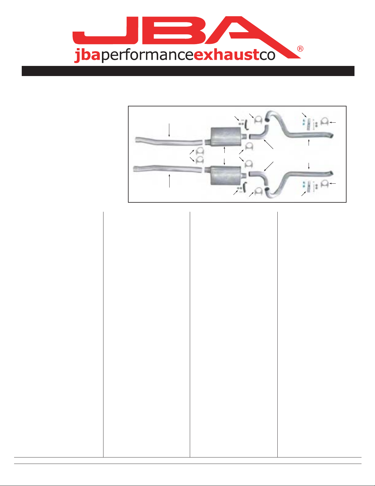
40-2650
(customer supplied mufflers use offset inlet/center outlet 14" body) Not shown
(shown)
‘65-‘70 Mustang V8 with
JBA H-pipe
Parts List:
A. P/S intermediate pipe 1
B. D/S intermediate pipe 1
C. JBA muffler 2
D. 90º bend 2
E. P/S tail pipe 1
F. D/S tail pipe 1
G. 2-1/2" Clamp 8
H. Universal Muffler hanger 2
I. Tailpipe hanger 1
Start:
Note-this system will not fit a
convertible. Tail pipe installation
should be performed with rear
axle at ride height. (Suspension
loaded)
Typically the stock exhaust
system on early cars is long
gone. These instructions
contemplate the installation of a
new JBA Exhaust System after
the original exhaust system has
been removed. This system is
designed to work with a JBA HPipe built for your application.
1. Remove and inventory the
JBA Exhaust System.
2. Disconnect the negative
battery cable and allow the
exhaust system to completely
cool.
3. With the H-Pipe installed, and
all exhaust removed from the
car, slip the intermediate pipes
onto the H-pipe. Orient them so
the small single bend is flat, and
pointing to the outside of the
car. The int. pipe should be just
below the seat belt bolt. If you
have replaced your factory bolts,
it may be necessary to shorten
an aftermarket bolt. Allow at
least a quarter inch clearance on
the bolt.
A
B
4. Slip a muffler clamp on each
exhaust pipe. Slip the mufflers on
to the Int. pipe. Align mufflers to
be flat with the floor, maintain
alignment with flat bend of the
intermediate pipe. The muffler
should have a minimum 1/2”
clearance to the front floor hump,
and a minimum 11/4” clearance
on top.
5. Support the muffler
temporarily. Universal hangers
are supplied with the kit, or you
can adapt your factory dual
hangers. If using the universal
hangers, self-tapping screws and
fender washers are supplied.
Position the hanger on the outlet
tube of the muffler. Mark the
floorboard at the sher onto the
S/T screw, slip the screw through
the hanger at whichever hole you
marked, slip another fender
washer on the screw, and attach
the hanger to the floor pan.
Fasten the hanger to the muffler
using a supplied clamp. Do both
sides; be sure to match muffler
heights.
6. The rear tail pipe hangers bolt
through the rear frame where the
shipping tie-down brackets bolt
on. If your car has these
brackets, they must be removed.
Assemble the grommet onto the
strap hanger. Slip a fender
washer onto the 3 1/2” bolt. Slip
the bolt through the frame at the
forward hole. Slip the
hanger/grommet assy. onto the
bolt. Add another fender washer
and a lock nut and tighten until
grommet just starts to compress.
H
G
7. Slip the tailpipes over the
axle. Install the small 90º bends,
long side into the muffler. Drop
the tail pipe onto the 90* bend.
Align the tailpipe so that it fits
into the notch in the floor pan,
just inside of the shock. Allow at
least 1/2” clearance on the floor.
8. On 2650 systems, position
the end of the tailpipe
approximately 3/4” below the
valance panel and
approximately 1/2” forward from
the edge. (Adjust front to rear
position at back of muffler.) Atta
justed” to clear the 2 1/2” pipe
and clamp. Usually a good
smack with your hand against
the tailpipe into the gas tank will
gain the necessary clearance.
9. On 2653 systems, follow
above instructions except
position tailpipe tips through
holes in rear valance. Align and
adjust for depth. Secure with
clamp to hanger.
10. Very Important- Once the
tailpipes are secured with the
rear clamp, the tails of the clamp
bolts must be trimmed off so
they don’t hang up on the leaf
spring.
11. Check the clearance of
exhaust to floor and rear axle
along the complete system.
Securely tighten all clamps.
Tack weld all slip joints.
C
G
H
G
G
I
G
E
D
F
G
I
We recommend taking the vehicle to a muffler shop and having all slip connections tack welded.
7/28/04
 Loading...