

Page 1
Corporate Ofce: PerTronix Inc. 440 E. Arrow Highway, San Dimas, California 91773 * Phone 909.599.5955 • FAX 909.599.6424
Installation Instructions
and Warranty Information
Toyota Tacoma & T-100 3.4
2032S 2001-04 Tacoma w/o EGR
2032S-1 1995-00 Tacoma w/o EGR
2032S-3 1995-01 T-100
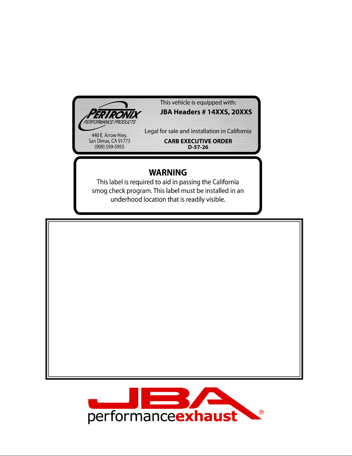
CARB EO # D-57-26
Read all instructions carefully before attempting installation.
Rev. 4 2-28-13 DSL
Page 2

PerTronix© thanks you for choosing JBA HEADERS, the best fitting, highest
quality header on the market. In order to realize the full potential of our good
fit, please read and understand these instructions completely prior to starting
work.
Check to make sure you received the proper parts for your application. The
header number will be stamped on the engine flange. If you are unsure you
have received the proper parts call before you start work.
Be sure to work safe! Whenever you work under the vehicle be sure that it
is located on level, solid ground and is supported by adequate safety stands!
Remember: Hot asphalt will not support most jack stands!
Many factors affect the installation of headers, some of which are broken or
aftermarket motor mounts, accidents that impact the configuration of the
frame, and/or the installation of different engines or aftermarket cylinder
heads.
Attention Customers breaking in new engines: Due to the extreme heat generated during the break-in process, the appearance of the ceramic coating may
be altered in certain areas. The protection characteristics and thermal barrier
properties of the coating is never compromised. It is recommended that a cast
iron manifold or old set of headers be used for this process.
Notice: The coating of these headers can be marred or scratched during installation. If the header needs to be returned and is damaged, you will be
charged for recoat.
JBA uses sealing beads on all its headers. We have found that when installed
correctly, the raised bead around each port increases the pressure exerted on the
gasket directly adjacent to the port and effectively prevents leaking gaskets. It is
normal for the flange to be raised off the cylinder head the thickness of the sealing
bead. It is important when installing the header, to install all bolts loosely, then
tighten evenly to ensure the flat installation of the flange. The torque sequence
from one flange to another will vary, but generally every bolt on a header should
be first fit snug, starting from the inside of the flange working out, alternating from
top to bottom so that the bolt connects the flange to the manifold to the point where
they barely touch. Second, using the same inside-out pattern, tighten each bolt un-
til finished. This method will help prevent leakage and will give the user the best
possible performance out of their pair of headers.
Page 3
1. Place vehicle in a location where the floor is solid and flat, with adequate lighting. Do not attempt to work on a hot engine. Heat
5b. Unbolting plenum support
causes metal to expand and makes removal of fasteners difficult at best. Disconnect the battery cables from the battery. Raise the front
of the vehicle to obtain adequate access to the bottom exhaust manifold anges. Use large-base jack stands to support the vehicle. Do
not rely on the jack! Block the tires to prevent the vehicle from rolling off the jack stands.
2. Spray WD-40 or some type of penetrating oil on all accessible exhaust fasteners and ttings before attempting to remove them.
3. Begin by removing the (4) screws that hold the stamped metal heat shields to each exhaust manifold then remove the shields.
4. For P/N 2032: Unbolt and remove the catalytic converter.
For 2032-1: Remove the exhaust pipe between the Y-pipe and the catalytic con-
verter.
5a. From underneath the vehicle, loosen the fasteners attaching the Y-pipe to the
exhaust manifolds.
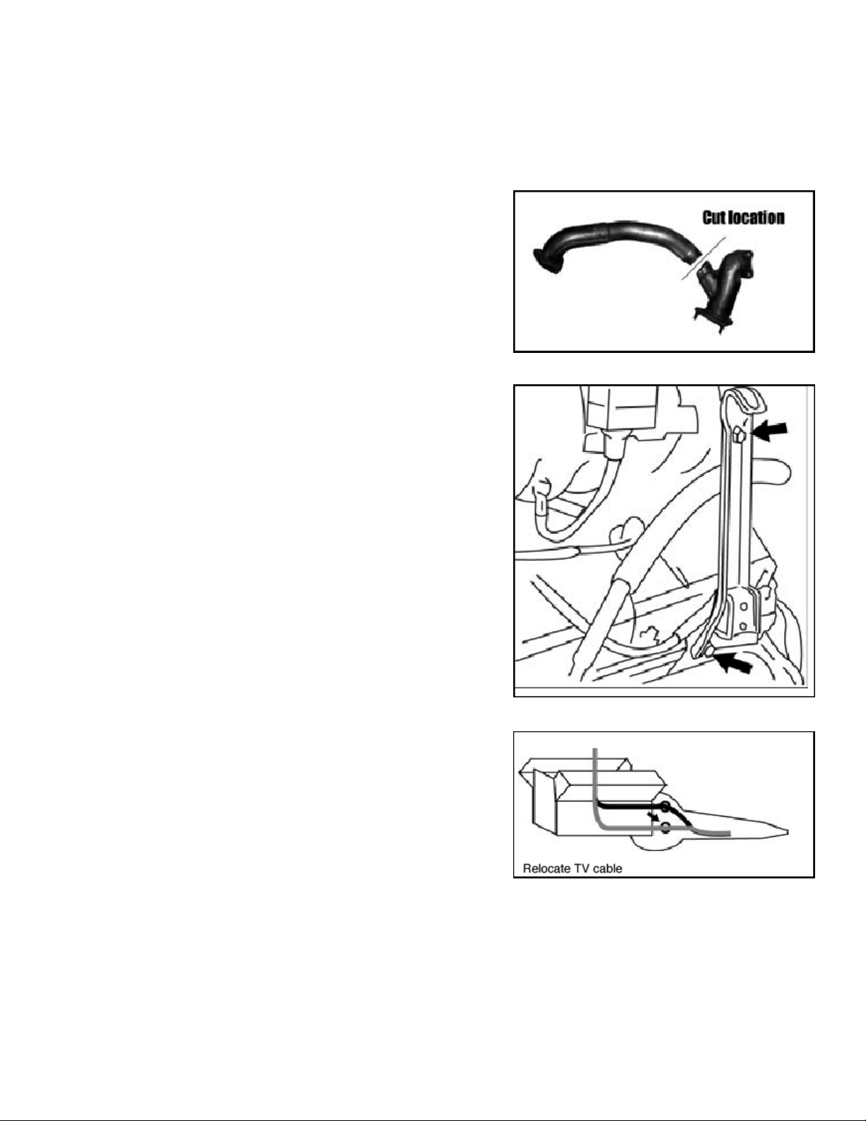
NOTE: The factory Y-pipe on Tacoma will not come out to see its own shadow
unless you (A) remove the cylinder heads or (B) cut it in half T-100s don ’t have
this problem. See the picture below for the proper cut location.
5b: Automatic Transmission Only: If equipped with an automatic transmission,
unclip the TV cable from the plenum support bracket. Unbolt the plenum support at the driver side rear corner. Then unbolt the auto transmission dipstick
tube from the cylinder head, but do not remove it.
6. Once the Y-pipe is removed, loosen the fasteners holding the exhaust mani-
folds to the cylinder heads. Remove the manifolds. With the manifolds off,
remove the studs from the cylinder heads.
7. Using a wire brush or scraper, remove any deposits from the head surface.
Be careful not to gouge the head.
8. Install the supplied exible heat shield on the driver side to cover the cool-
ant lines behind the motor mount. Secure the heat shield in place using the
supplied safety wire.
9. Place the new crossover tube behind the cylinder heads with the 90-degree
bend on the driver side.
10. On the driver side, remove the lower 90-degree wire loom former and
reshape the loom to remove the kink. Loosen the lower bracket and reposition
it to hold the wire loom under it.
11. Using the supplied hardware and gaskets, install the new JBA Headers.
The small header goes on the driver side the longer one goes on the passenger
side. Remove the bolt holding the TV cable to the bell housing on the driver
side. Relocate the cable to the position shown.
12. Using the supplied fasteners, loosely attach the crossover pipe to the driver
side header with the supplied metal O-ring gasket in place.
13. Connect the new JBA Y-pipe to the passenger side header and the crossover pipe using the supplied hardware. For auto transmission, re-install the
transmission dipstick and tube using the supplied spacer and bolt.
14. Connect the new Y-pipe to the catalytic converter assembly
For 2032: The original connector pipe must be cut from the converter and the new one welded on.
For 2032-1: The Y-pipe will bolt directly to the factory catalytic converter assembly
15. Remove the O2 sensors from the factory exhaust and transfer them to the new JBA parts.
16. Check the tightness of all fasteners, check for adequate clearance on all fuel, brake, oil, coolant lines, etc.
17. Start the engine and check for leaks. Allow the engine to warm up and then turn engine off. Let the exhaust cool then re-torque all
fasteners.
Page 4
Parts List:
(1) Driver side header (3) 3/8 x 1-1/2 Bolts with lock washers and nuts
(1) Passenger side header (1) O-ring gasket (metal)
(1) Cross over pipe (1) EGR gasket
(1) Y-pipe (2) Head flange gaskets
(12) 10mm -1.25 x 25 bolts and lock washers (1) 5 x 7 flexible heat shield
(1) Safety wire (16 ”long) (2) 8mm nuts
(2) 8mm lock washers (1) Trans dipstick tube spacer,10mm x 35 bolt
(6) 5/16 x 2 ”collector bolts, flat washers, lock washers and nuts
LIMITED ONE YEAR WARRANTY
All JBA HEADERS and exhaust products are guaranteed, to the original purchaser, to be free of defects in materials and workmanship for one year. This warranty
covers the replacement or repair of the product only and does not cover the cost
of removal and installation, customer applied aftermarket coatings or any discolor-
ation or corrosion of nished surfaces.
Damage or product failure resulting from collision, improper installation, off-road
use, road hazards, the use of exhaust insulating wrap or like products or rust occurring after installation, is not covered by the warranty. The warranty extends only
to the original purchaser.
Should a part become defective it should be returned to the original selling retailer
and must be accompanied with the sales receipt. If there is no retailer in your area,
call the factory for a return authorization and return your part prepaid to the factory
for inspection. PerTronix reserves the rights to replace or repair the alleged defective part and return the part freight collect.
Page 5

 Loading...