

Page 1
ELIMINATOR
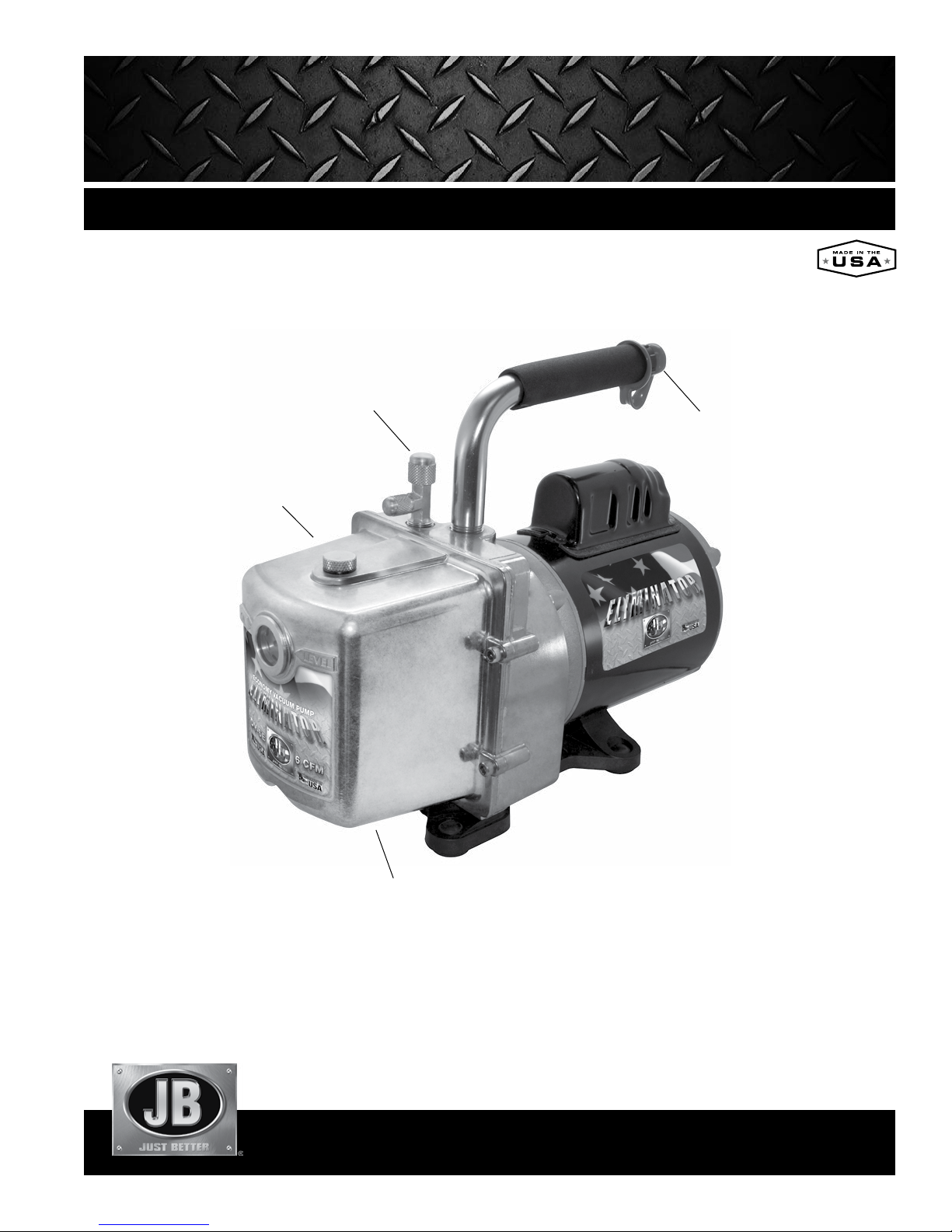
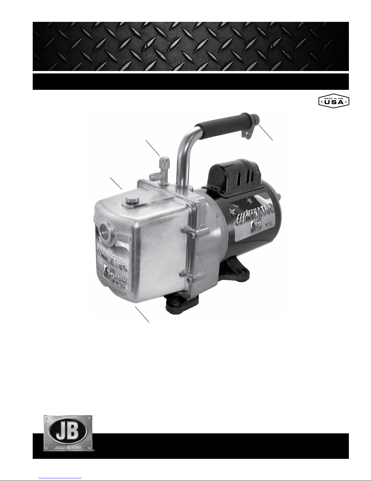
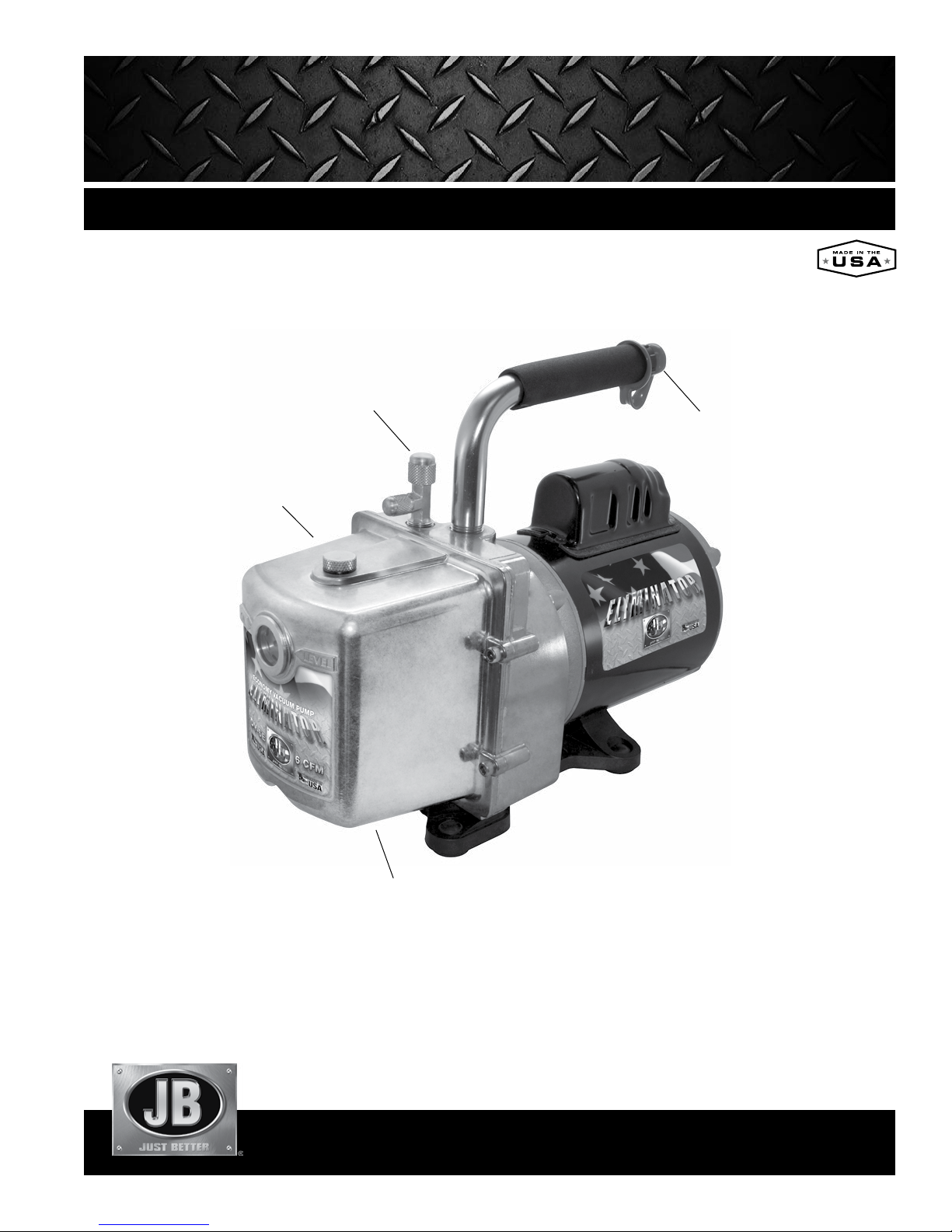
Oil Fill Plug
(Do not wrench down
or use sealant on threads)
®
2-STAGE DIRECT DRIVE VACUUM PUMP
Intake
Exhaust
OPERATING MANUAL
WARNING: UNIT DRAINED OF OIL FOR SHIPMENT. DO NOT OPERATE WITHOUT ADDING OIL.
Oil Drain Valve
(Close drain finger-tight)
CONTENTS
Introduction . . . . . . . . . 2
Motor Specifications. . . . . 2
Operation. . . . . . . . . . . 3
Pump Maintenance . . . . . 2
Repair Parts . . . . . . . . . 3
Troubleshooting . . . . . . . 4
Return for Repair . . . . . . 4
Warranty . . . . . . . . . . . 4
Accessories . . . . . . . . . 4
Page 2
INTRODUCTION
♦
Each ELIMINATOR vacuum pump has been factory tested to guarantee 25 microns
(25,400 Microns = 1 Inch of Hg) or better, and listed CFM performance. The serial
number has been recorded. Complete and mail the enclosed Warranty Registration
Card or register online at www.jbind.com within 10 days of purchase to validate
your warranty.
PUMP MAINTENANCE
In order to make the best use of your investment, familiarize yourself with the
features and operating instructions before starting pump. With routine care and
following proper maintenance guidelines, your ELIMINATOR will give you years
of reliable service. ELIMINATOR pumps are designed for deep vacuum work in air
conditioning and refrigeration systems.
NOTE: ELIMINATOR pumps are not to be used on Ammonia or Lithium Bromide
(salt water) systems. Pump maintenance is the responsibility of the owner.
MOTOR SPECIFICATIONS
Pump and oil must be above 30°F. Line voltage must be equal to motor nameplate
±10%. Normal operating temperature is approximately 160°F, which is hot to the
touch. Line voltage and ambient conditions can slightly affect this. Motor has
automatic resetting thermal overload protection.
The ELIMINATOR is designed for continuous duty and will run for extended periods
without overheating.
US DOMESTIC
DV-3E DV-4E DV-6E
CFM
Motor
Voltage
Intake Port
Oil Capacity
3 CFM (85 l/m) 4 CFM (113 l/m) 6 CFM (170 l/m)
1/2 HP, 1725 RPM 1/2 HP, 1725 RPM 1/2 HP, 1725 RPM
115v, 60 Hz 115v, 60 Hz 115v, 60 Hz
1/4" x 3/8" 1/4" x 3/8" 1/4" x 3/8"
28 oz (828 cc) 25 oz (739 cc) 25 oz (739 cc)
DUAL VOLTAGE
DV-3E-250 DV-4E-250 DV-6E-250
Motor
Voltage
1/2 HP,
1725/1425 RPM
115v, 60 Hz
230v, 50 Hz
1/2 HP,
1725/1425 RPM
115v, 60 Hz
230v, 50 Hz
1/2 HP,
1725/1425 RPM
115v, 60 Hz
230v, 50 Hz
OPERATION
The following procedures will prevent oil from being drawn into the pump cartridge
and creating hard start-up.
Start-up: Close both sides of manifold and make connection to vacuum pump or
auxiliary blank-off equipment. Start pump.
Shut down: Crack open unused port to break vacuum. Allow pump to run
2-3 seconds. Shut down and remove hose connections and cap intakes.
For a complete overview of proper care and pump maintenance, refer to the
Keeping the Life in your Pump guide available online at www.jbind.com.
Adding Oil
Pump oil acts simultaneously as a coolant, lubricant and sealant.
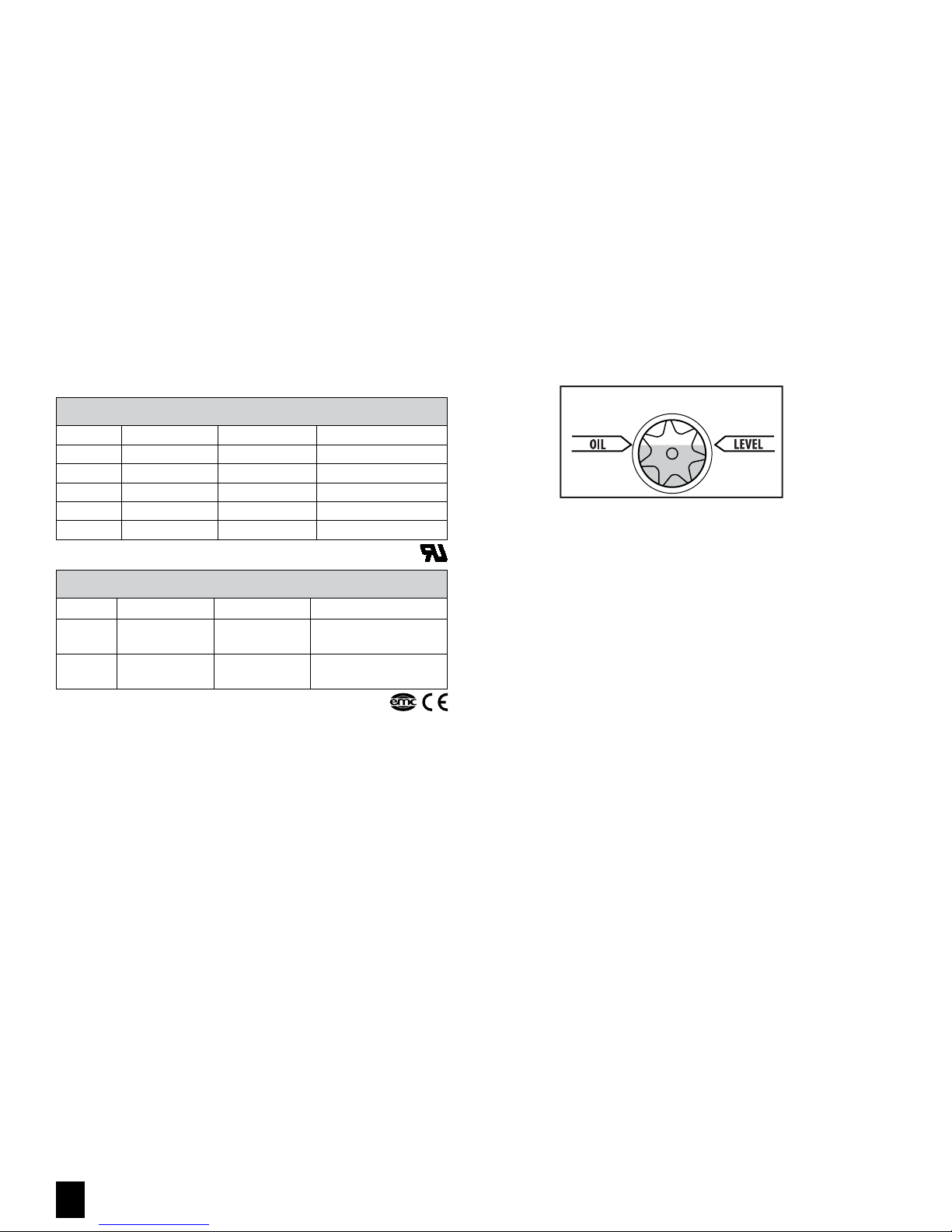
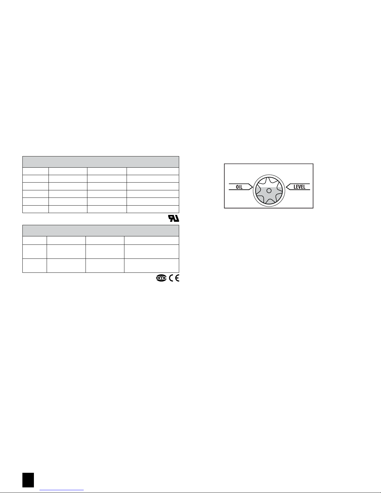
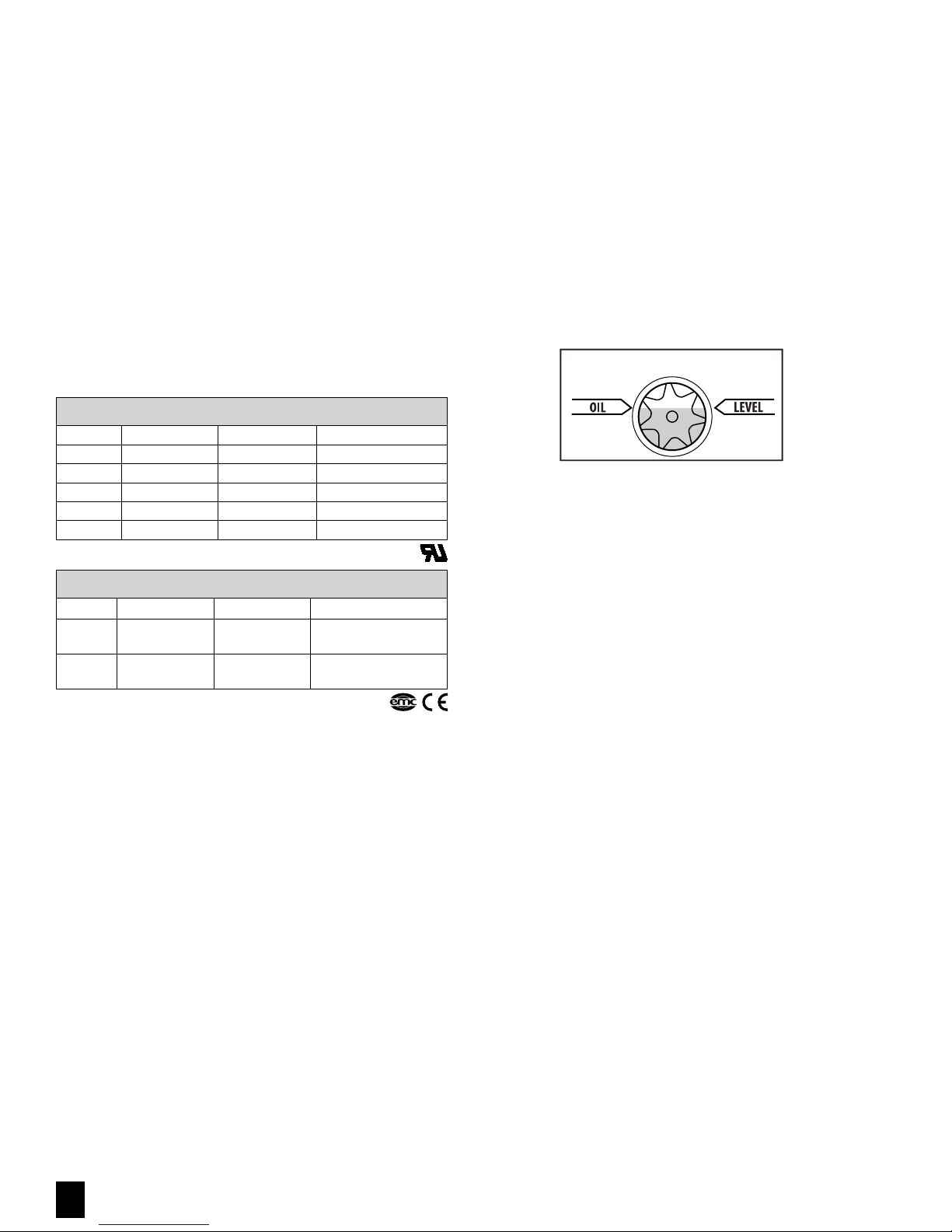
1. Slowly add oil until oil level rises to the top of the oil level line.
2. Replace oil fill plug.
If oil is too low, you will hear air out of the exhaust. If the oil level is too high,
excess oil will be blown out of the exhaust.
IMPORTANT: OIL LEVEL MUST BE ABOVE
HALF WAY IN SIGHT GLASS
IMPORTANT: Use oil specifically refined for deep vacuum pumps. Using oil not
refined for deep vacuum pumps and/or operating with contaminated oil will void
warranty.
Pump oil should be changed after each use. If system is heavily contaminated,
oil may have to be changed several times during evacuation. After initial fill up,
it is best to check oil level with pump running.
After evacuation, oil contains rust forming water and corrosive acids. Drain
immediately while pump is warm.
Changing Oil
To reach deep vacuum, ELIMINATOR pumps need clean, moisture-free oil
throughout evacuation. Care should be taken to avoid contact on skin and clothing
when changing oil. Used oil should be disposed of in the DV-T1 TANK oil caddy
after every evacuation while the pump is warm and the oil is thin.
1. Place the TANK on a level surface. Unscrew black plug counterclockwise in drain
base to open.
2. Place vacuum pump in the cradle and drain pump.
3. Once the pump has finished draining, turn the black cap clockwise to close after
every use (the TANK can hold up to five oil changes).
JB INDUSTRIES • ELIMINATOR Operating Manual • 800.323.0811 • [email protected]
2
4. Close drain on pump. Remove oil fill cap and fill to top of oil level line with
BLACK GOLD Pump Oil. Replace oil fill cap.
Flushing Oil
1. Always drain pump before flushing. If the oil is badly contaminated, flushing
may be necessary.
2. Slowly pour 1/3 to 1/2 cup of BLACK GOLD Pump Oil into the intake connection
while pump is running.
3. Repeat as required until contamination is removed from oil reservoir, pump
rotors, vanes and housing.
4. Dispose of all oil used in flushing of pump.
WARNING: DO NOT START PUMP BEFORE ADDING OIL
Page 3
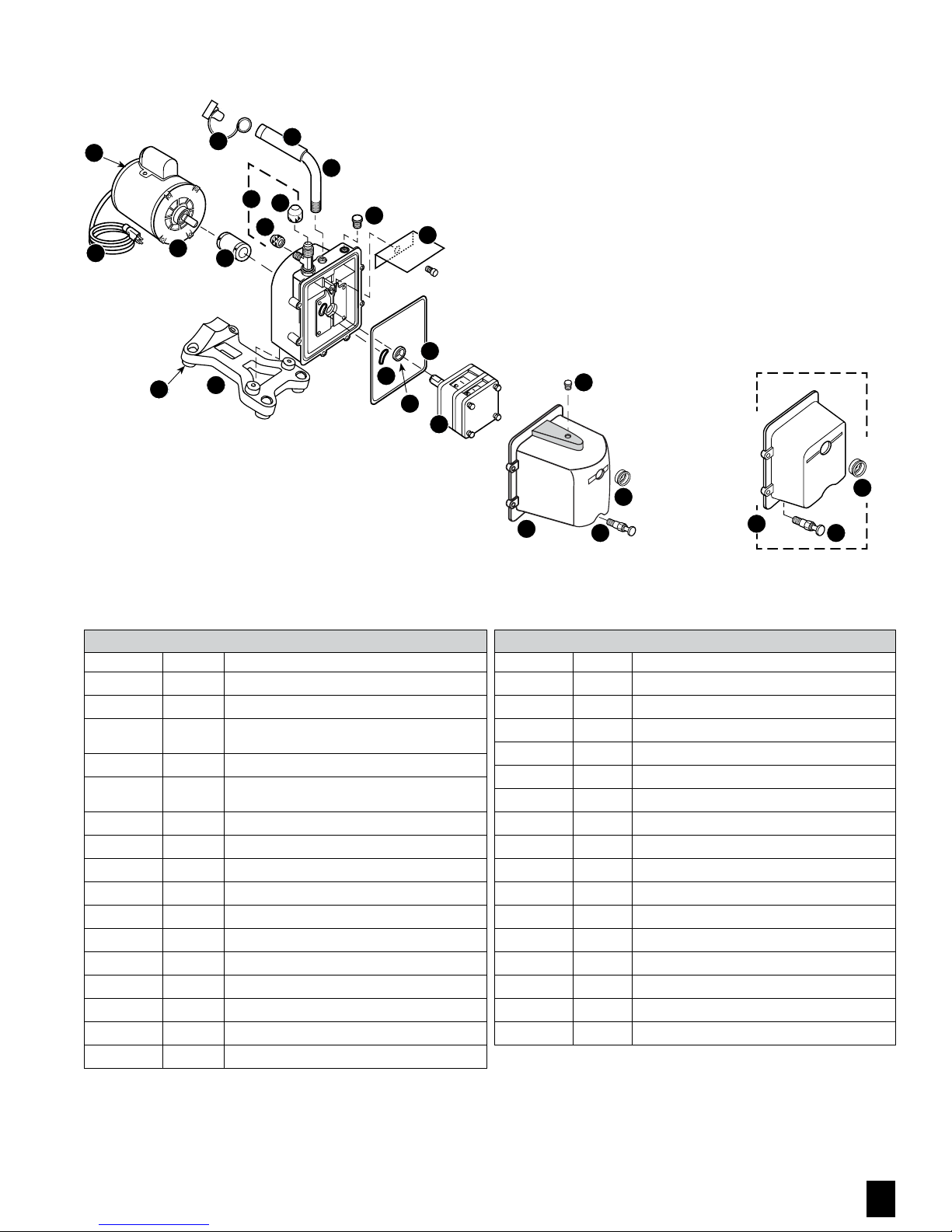
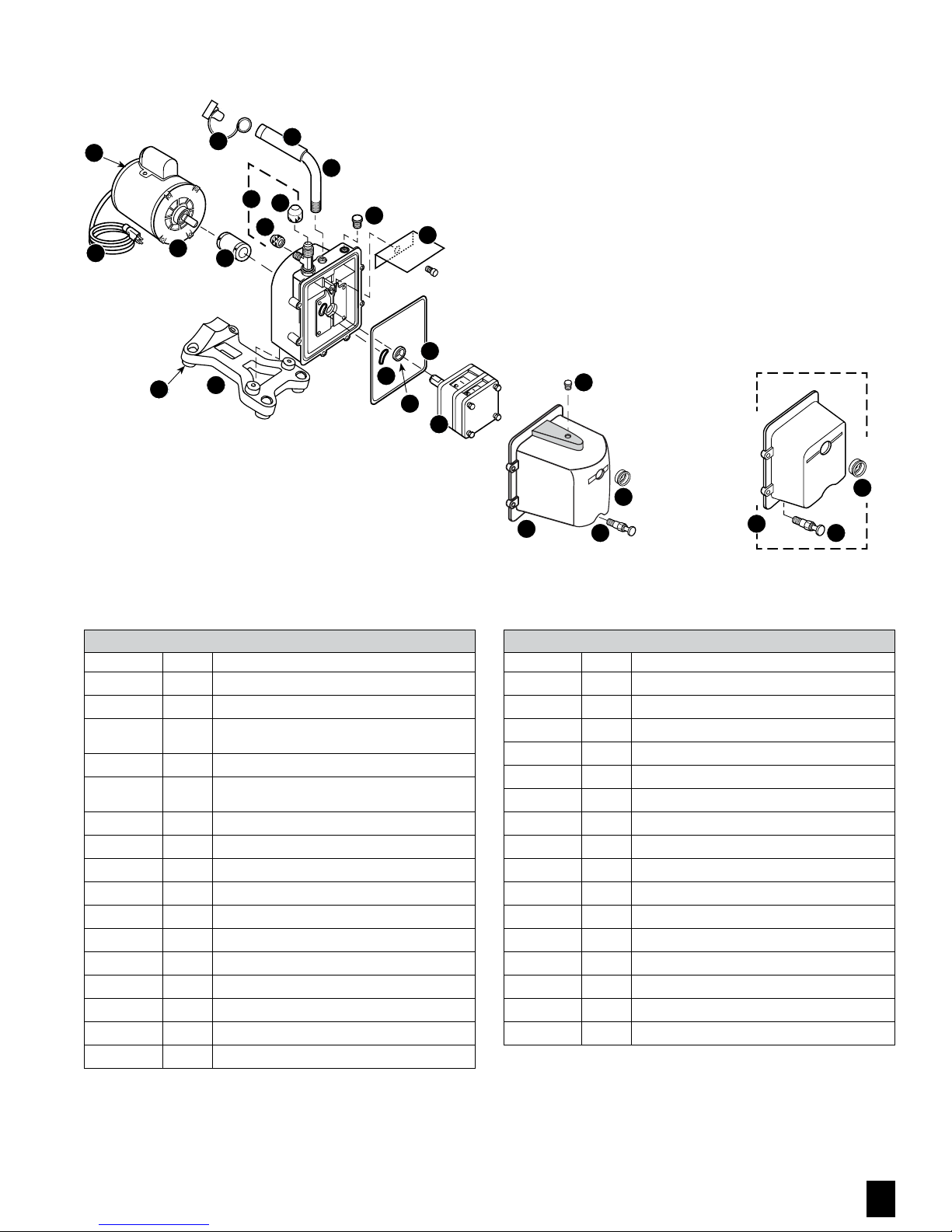
REPAIR PARTS
13
12
10
20
17
21
14
16
15
11
8
18
19
5
9
7
18
6
4
1
3
2
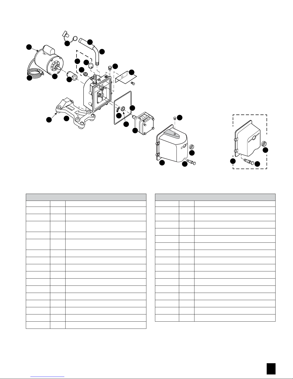
Current chrome cover will fit older black
Eliminator models.
3
Black hammertone cover
no longer available
1
2
ELIMINATOR SERIES DV-3E, DV-4E AND DV-6E REPAIR PARTS
Ref. No. Part No. Description
1
2
3
4
4
4
5
6
7
8
8
8
8
9
10
Not Shown
Emerson® is a registered trademark of US Motors. Marathon® is a registered trademark of Marathon Electric.
PR-1
PR-2
PR-10
PR-403
PR-404
PR-406
PR-217
PR-3
PR-315
PR-208
PR-308
PR-6
PR-77
PR-62
PR-59
PR-18
Sight glass
Drain valve
DV-3E, DV-4E and DV-6E cover assembly w/sight glass, drain
valve and oil fill plug
DV-3E Cartridge complete w/o-rings and cover seal
DV-4E Cartridge complete w/o-rings and cover seal
DV-6E Cartridge complete w/o-rings and cover seal
Cover seal
Shaft seal
Trap intake o-ring
Flexible coupler
Middle section; used w/PR-208 flexible coupler
Flexible coupler
Middle section; used w/PR-6 flexible coupler
Pump base (includes rubber feet)
Rubber foot
Cartridge valve repair kit
ELIMINATOR SERIES DV-3E, DV-4E AND DV-6E REPAIR PARTS
Ref. No. Part No. Description
11
11
12
12
13
14
15
16
17 Black
17 Silver
18
19
20 Black
20 Silver
21 Black
21 Silver
PR-207
PR-206
PR-31
PR-58
PR-54
PR-63
NFT5-4
NFT5-6
PR-500
PR-501
PR-22
PR-40
DV-EP6
DV-EP8
PR-205
PR-65
1/2 HP, 115/230v, 50/60 Hz motor w/line cord and switch
1/2 HP motor w/line cord and switch
®
Line cord (Emerson
Line cord (Marathon
Motor switch, rocker
Intake tee w/cap
1/4" O-ring cap
3/8" O-ring cap
3/8" Rubber grip and cap
1/2" Rubber grip and cap
Oil fill plug w/o-ring
DV-4E and DV6E splash guard w/screw
Tethered safety plug 3/8"
Tethered safety plug 1/2"
Cushioned handle 3/8" NPT
Cushioned handle 1/2" NPT
motor)
®
motor)
JB INDUSTRIES • ELIMINATOR Operating Manual • 800.323.0811 • [email protected]
3
Page 4
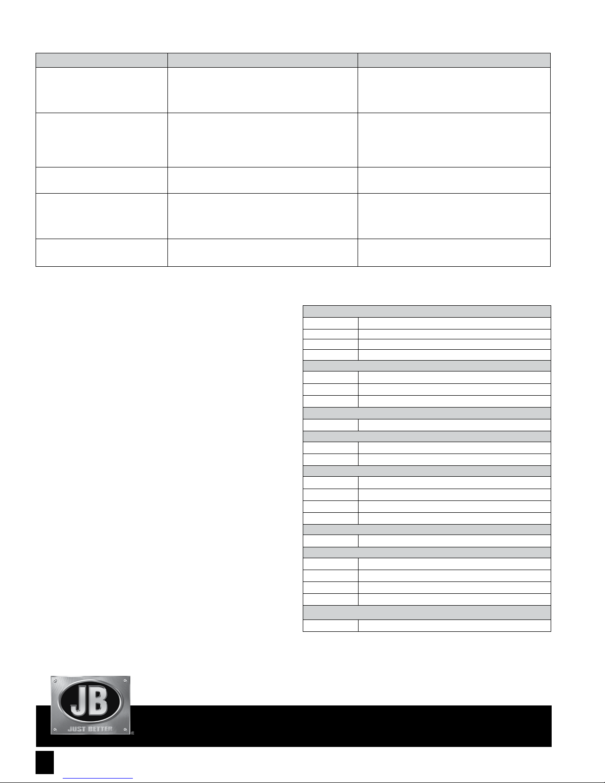
TROUBLESHOOTING
SYMPTOM POSSIBLE CAUSE(S) CORRECTIVE ACTION
Pump won’t start
1. Power cord not plugged in securely
2. Motor switch not on
3. Pump temperature below 30°F
4. Inconsistent line voltage
1. Plug power cord in securely
2. Turn motor switch to ON position
3. Warm up pump to 30°F and turn motor switch on
4. Line voltage must be within 10% of 115v
Pump won’t pull deep vacuum
Oil drips from point where shaft enters the
pump housing
Pump shuts down and will not start
Pump cycles on and off from a completely
cold start and then runs smoothly
1. Contaminated oil
2. Oil level too low
3. Air leak in system being evacuated
4. Pump inlet fittings missing or not tightened
5. Coupler slipping
Damaged shaft seal Replace shaft seal
Thermal overload may be open 1. Disconnect pump from system
1. Oil backed up into cartridge and was being cleared out
2. Pump has not been shut down properly
RETURN FOR REPAIR
in the event your pump requires repair, please contact JB Customer Service
Department to obtain a Return Goods Authorization (RGA) number. Ensure that all
returned products are packed to avoid any damage in shipment. Paperwork should
be placed in a separate plastic bag and should include JB’s assigned RGA number,
a description of the problem and any customer assigned repair or purchase order
number, if applicable.
Contact Customer Service for RGA number:
800.323.0811 Toll
800.552.5593 Toll Fax
Customers in Alaska, Arizona, California, Idaho, Montana, Nevada, Oregon, Utah, and Washington have
the option of sending vacuum pump repairs to JB or Merced.
JB Industries
RGA#_________
601 N. Farnsworth Ave.
Aurora, IL 60505
630.851.9444 Tel
630.851.9448 Fax
Merced AC Equipment Service
RGA#_________
805 S. Fremont
Alhambra, CA 91803
626.293.5710 Tel
626.289.1961 Fax
WARRANTY
ELIMINATOR pumps are warrantied against defects in materials and workmanship
for 24 months—not changing oil will void warranty. JB products are guaranteed
when used in accordance with our guidelines and recommendations. Warranty is
limited to the repair, replacement, or credit at invoice price, (our option) of products
which in our opinion are defective due to workmanship and/or materials. In no
case will we allow charges for labor, expense or consequential damage. Repairs
performed on items out of warranty will be invoiced on a nominal basis; contact
wholesaler for details. Product Warranty Registration, Limited Warranty and OTC
Warranty are available online at www.jbind.com.
1. Change oil
2. Add oil
3. Locate and repair leak(s)
4. Clean or replace o-ring
5. Tighten coupler setscrews to flats of cartridge and motor
2. Wait approximately 15 minutes for motor to cool
3. Turn pump on
4. If it cycles off again, return pump to factory for repair
1. Remove 1/4" cap
2. Turn pump on
ACCESSORIES
Part No. Description
DV-40S
DV-41
DV-22N
DVO-1
DVO-12
DVO-24
DV-T1
DV-F6
DV-F8
D10244
D10266
P90009
P90012
D10162
QC-E64
QC-S64
P90009
P90012
VL-100
Wireless Micron Gauge w/mobile app
Digital Micron Gauge
Digital Vacuum Gauge
BLACK GOLD VACUUM PUMP OIL
Black Gold Vacuum Pump Oil (Pint; Case of 24)
Black Gold Vacuum Pump Oil (Quart; Case of 12)
Black Gold Vacuum Pump Oil (Gallon; Case of 6)
THE TANK VACUUM PUMP OIL CADDY
Empty tank
Oil mist filter 3/8"
Oil mist filter 1/2"
1/4" Female swivel coupler
3/8" Female swivel coupler
1/4" Replacement o-ring (10 pack)
3/8" Replacement o-ring (10 pack)
1/4" Female QC x 1/4" flare
3/8" QC x 1/4" SAE elbow
3/8" QC x 1/4" SAE straight
1/4" Replacement o-ring (10 pack)
3/8" Replacement o-ring (10 pack)
VELOCITY RAPID EVACUATION KIT
Evacuation kit w/hose and valve core removal tool
MICRON GAUGES
OIL MIST FILTER
SWIVEL COUPLERS
SHUT-OFF VALVE
QUICK COUPLERS
JB INDUSTRIES
JB INDUSTRIES • ELIMINATOR Operating Manual • 800.323.0811 • [email protected]
4
©2017 JB Industries, Inc. Printed in the USA
Form No. 10346-308 0217
Page 5
ELIMINATOR
2 ETAPAS DE TRANSMISIÓN DIRECTA BOMBA DE ALTO VACÍO
TAPÓN DE LLENADO DE ACEITE
No arrancar abajo o usar sellador en las roscas
®
INGESTA
ESCAPE
MANUAL DE INSTRUCCIONES DE OPERACIÓN Y PARTES
IMPORTANTE: ESTA UNIDAD HA SIDO DRENADO DEL ACEITE PARA SU ENVÍO. NO INTENTE OPERAR SIN ADICIÓN DE ACEITE.
VALVULA DE DRENAJE DE ACEITE
Cerrar dedo drenaje apretado
TABLA DE CONTENIDOS
Introducción . . . . . . . . . 2
Motor Especificaciones . . . 2
Operación . . . . . . . . . . 3
Bomba Mantenimiento . . . 2
Las partes de repuesto . . . 3
Solución de problemas . . . 4
Devolución Para
La Reparación . . . . . . . . 4
Garantía . . . . . . . . . . . 4
Accesorios . . . . . . . . . . 4
Page 6
INTRODUCCIÓN
♦
Cada bomba ELIMINATOR ha sido evaluada en fábrica para que garantice 25
micrones (25,400 micrones = 1 pulgada) al menos y el rendimiento en CFM
indicado. El número de serie ha sido registrado. Llene y envíe por correo la Tarjeta
de Inscripción de Garantía dentro de los 10 días de compra para confirmar su
garantía. Le notificaremos sobre cualquier actualización técnica.
NOTA: No para el uso en sistemas del amonia o sistemas del bromuro del litio.
MOTOR ESPECIFICACIONES
La temperatura de la bomba y del aceite debe estar por encima de los 30 °F.
El voltaje de línea debe ser igual al de la placa de identificación del motor
±10%. La temperatura normal de operación es aproximadamente 160°F, que es
una temperatura caliente al tacto. La temperatura será afectada un poco por el
voltaje de línea y las condiciones ambientales. El motor tiene protección contra
sobrecarga térmica con restablecimiento automático. La bomba ELIMINATOR está
diseñada para servicio continuo y funcionará durante períodos prolongados sin
sobrecalentarse.
US DOMESTIC
DV-3E DV-4E DV-6E
CFM
Motor
Voltage
Intake Port
Oil Capacity
Motor
Voltage
3 CFM (85 l/m) 4 CFM (113 l/m) 6 CFM (170 l/m)
1/2 HP, 1725 RPM 1/2 HP, 1725 RPM 1/2 HP, 1725 RPM
115v, 60 Hz 115v, 60 Hz 115v, 60 Hz
1/4" x 3/8" 1/4" x 3/8" 1/4" x 3/8"
28 oz (828 cc) 25 oz (739 cc) 25 oz (739 cc)
DUAL VOLTAGE
DV-3E-250 DV-4E-250 DV-6E-250
1/2 HP,
1725/1425 RPM
115v, 60 Hz
230v, 50 Hz
1/2 HP,
1725/1425 RPM
115v, 60 Hz
230v, 50 Hz
1/2 HP,
1725/1425 RPM
115v, 60 Hz
230v, 50 Hz
BOMBA MANTENIMIENTO
A fin de darle el mejor uso a su inversión, familiarícese con las nuevas
características e instrucciones de operación antes de poner la bomba en
funcionamiento. Con sólo un cuidado rutinario, su ELIMINATOR le dará años de
servicio confiable siguiendo las pautas apropiadas de mantenimiento. Las bombas
ELIMINATOR están diseñadas para un trabajo de alto vacío en los sistemas de aire
acondicionado y de refrigeración.
IMPORTANTE: Use aceite específicamente refinado para las bombas de alto vacío.
La garantía quedará anulada si usa aceite no refinado para bombas de alto vacío
o si opera con aceite contaminado.
ACEITE
Agregue aceite lentamente hasta que el nivel suba hasta la línea OIL LEVEL.
Reinstale el tapón del depósito de aceite. Si el nivel de aceite es demasiado bajo,
se escuchará un traqueteo en el deflector del tubo de escape. Si el nivel de aceite
es muy alto, el exceso de aceite será eliminado por el escape.
Debe cambiar el aceite de la bomba luego de cada uso. Si el sistema está muy
contaminado, se debe cambiar el aceite varias veces durante la evacuación.
IMPORTANT: OIL LEVEL MUST BE ABOVE
HALF WAY IN SIGHT GLASS
Después de la evacuación, el aceite contiene óxido el cual forma agua y ácidos
corrosivos. Drene de inmediato mientras la bomba aún está caliente.
CAMBIO DE ACEITE
Para lograr un alto vacío, las bombas ELIMINATOR necesitan aceite limpio y sin
humedad durante toda la evacuación. Tenga mucho cuidado para evitar que entre
en contacto con la piel y la ropa al cambiar el aceite. Se debe desechar el aceite
usado en un recipiente resistente a la corrosión y a prueba de fugas.
OPERACIÓN
Los siguientes procedimientos evitarán que el aceite sea absorbido dentro del
cartucho y que el arranque tenga problemas.
ARRANQUE: Cierre ambos lados del múltiple y conecte a la bomba de vacío o
equipo de obturación auxiliar. Arranque la bomba.
APAGADO: Abra el orificio sin uso para interrumpir el vacío. Deje que la bomba
funcione de 2 a 3 segundos. Apague y retire las conexiones de manguera y las
tapas de la entrada.
1. Después de cada evacuación, cuando la bomba aún esté caliente y el aceite
esté delgado, coloque la bomba en una superficie nivelada y abra el drenaje
del aceite. El aceite puede ser extraído de la bomba al abrir una entrada y
bloquear parcialmente el escape con un pedazo de tela mientras la bomba está
en funcionamiento. No haga funcionar la bomba por más de 5 minutos usando
este método.
2. Cierre el drenaje. Retire la tapa depósito de aceite y llene hasta la línea OIL
LEVEL con Aceite para bomba de vacío JB. Reinstale la tapa del depósito
de aceite.
LAVADO
SIEMPRE DRENAJE BOMBA ANTES DE LAVAR! En caso de que el aceite esté
demasiado contaminado, podría ser necesario lavarlo. Vierta lentamente entre
1/3 y 1/2 taza de aceite para bomba de vacío JB en la conexión de entrada
mientras la bomba está en funcionamiento. Repita el procedimiento las veces que
sea necesario hasta que se haya eliminado la contaminación de los recipientes
de aceite, rotores de la bomba, álabes y de la carcasa. Deseche todo el aceite que
usó durante el lavado de la bomba.
IMPORTANTENO ARRANQUE LA BOMBA ANTES DE AÑADIR EL ACEITE
JB INDUSTRIES • ELIMINATOR Manual De Instrucciones De Operación Y Partes • 800.323.0811 • [email protected]
2
Page 7
PARTES DE REPUESTO
13
12
10
20
17
21
14
16
15
11
8
18
19
5
9
7
18
6
4
1
3
Nueva cubierta cabrá Viejo Negro
Eliminadores Eliminators
2
®
3
Ya no está disponible
1
2
ELIMINATOR LAS PARTES DE REPUESTO DE LA BOMB
No. De Ref. No. De Pa rt Descripción
1
2
3
4
4
4
5
6
7
8
8
8
8
9
10
Not Shown
Emerson® es una marca registrada de US Motors. Marathon® es una marca registrada de Marathon Electric.
PR-1
PR-2
PR-10
PR-403
PR-404
PR-406
PR-217
PR-3
PR-315
PR-208
PR-308
PR-6
PR-77
PR-62
PR-59
PR-18
Sight glass
Drain valve
DV-3E, DV-4E and DV-6E cover assembly w/sight glass, drain
valve and oil fill plug
DV-3E Cartridge complete w/o-rings and cover seal
DV-4E Cartridge complete w/o-rings and cover seal
DV-6E Cartridge complete w/o-rings and cover seal
Cover seal
Shaft seal
Trap intake o-ring
Flexible coupler
Middle section; used w/PR-208 flexible coupler
Flexible coupler
Middle section; used w/PR-6 flexible coupler
Pump base (includes rubber feet)
Rubber foot
Cartridge valve repair kit
ELIMINATOR LAS PARTES DE REPUESTO DE LA BOMB
No. De Ref. No. De Par t Descripción
11
11
12
12
13
14
15
16
17 Black
17 Silver
18
19
20 Black
20 Silver
21 Black
21 Silver
PR-207
PR-206
PR-31
PR-58
PR-54
PR-63
NFT5-4
NFT5-6
PR-500
PR-501
PR-22
PR-40
DV-EP6
DV-EP8
PR-205
PR-65
1/2 HP, 115/230v, 50/60 Hz motor w/line cord and switch
1/2 HP motor w/line cord and switch
®
Line cord (Emerson
Line cord (Marathon
Motor switch, rocker
Intake tee w/cap
1/4" O-ring cap
3/8" O-ring cap
3/8" Rubber grip and cap
1/2" Rubber grip and cap
Oil fill plug w/o-ring
DV-4E and DV6E splash guard w/screw
Tethered safety plug 3/8"
Tethered safety plug 1/2"
Cushioned handle 3/8" NPT
Cushioned handle 1/2" NPT
motor)
®
motor)
JB INDUSTRIES • ELIMINATOR Manual De Instrucciones De Operación Y Partes • 800.323.0811 • [email protected]
3
Page 8
SOLUCIÓN DE PROBLEMAS
SÍNTOMA CAUSA(S) POSIBLE(S) MEDIDA CORRECTIVA
La bomba no arranca
1. El cordón de alimentación no está firmemente conectado
2. El interruptor del motor no está encendido
3. La temperatura de la bomba está por debajo de los 30°F
4. El voltaje de línea es irregular
1. Conecte el cordón de alimentación firmemente
2. Encienda el interruptor del motor
3. Caliente la bomba hasta 30°F y encienda el interruptor del motor
4. El voltaje de línea debe estar dentro del 10% de 115 voltios
La bomba no forma alto vacío
Goteo de aceite en el lugar donde el eje
hace contacto con la carcasa de la bomba
La bomba se apaga y no arranca
La bomba se enciende y se apaga desde
un arranque en frío y luego funciona sin
problemas
1. El aceite está contaminado
2. El nivel de aceite es demasiado bajo
3. Hay fuga de aire durante la evacuación del sistema
4. Las conexiones de entrada de la bomba no están completas o no
están apretadas
5. El acoplamiento se desliza
Sello del eje dañado Reemplácelo
La protección contra sobrecarga térmica puede haber disparado 1. Desconecte la bomba del sistema
1. El aceite se acumuló en el cartucho y se estaba eliminando
2. La bomba no fue apagada correctamente
DEVOLUCIÓN PARA LA REPARACIÓN
Se han hecho todos los esfuerzos para proporcionar productos fiables y de calidad
superior. Sin embargo, en caso de que su bomba requiera reparación, póngase en
contacto con el Departamento de Servicio al Cliente de JB para obtener un número
de autorización de devolución de mercancías (RGA). Asegúrese de que todos los
productos devueltos estén embalados para evitar daños en el envío. El papeleo
debe colocarse en una bolsa de plástico separada y debe incluir el número RGA
asignado de JB, una descripción del problema y cualquier número de pedido o
reparación asignado por el cliente, si corresponde.
Póngase en contacto con el servicio
de atención al cliente para el número RGA:
800.323.0811 Toll
800.552.5593 Toll Fax
Clientes en Alaska, Arizona, California, Idaho, Montana, Nevada, Oregon, Utah, and Washington tienen
la opción de enviar reparaciones de la bomba de vacío a JB oa Merced.
JB Industries
RGA#_________
601 N. Farnsworth Ave.
Aurora, IL 60505
630.851.9444 Tel
630.851.9448 Fax
Merced AC Equipment Service
RGA#_________
805 S. Fremont
Alhambra, CA 91803
626.293.5710 Tel
626.289.1961 Fax
GARANTÍA
Las bombas ELIMINATOR están garantizadas contra defectos de materiales y
mano de obra por 2 años. Todos los productos JB están garantizados si se usan
siguiendo nuestras instrucciones y recomendaciones; esta garantía queda limitada
a reparaciones, reemplazos, o crédito en el precio de venta (a nuestra elección)
de productos que a nuestra consideración tengan defectos debido a mano de
obra o materiales. Bajo ninguna circunstancia aceptaremos cargos por mano de
obra, gastos o daños emergentes. Las reparaciones de artículos no incluidos en
la garantía serán cobradas sobre una base del valor nominal. Contáctese con su
mayorista para mayores detalles.
1. Cambie el aceite
2. Agregue aceite
3. Ubique las fugas y repárelas
4. Limpie o reemplace el anillo tórico
5. Apriete los tornillos de ajuste del acoplamiento en la parte plana del
cartucho y del motor
2. Deje que el motor se enfríe aproximadamente 15 minutos y vuelva a
encenderlo
3. Si se apaga nuevamente, devuelva la bomba a la fábrica para su
reparación
1. Retire la tapa de 1/4”
2. Encienda la bomba
ACCESSORIES
Part No. Description
DV-40S
DV-41
DV-22N
DVO-1
DVO-12
DVO-24
DV-T1
DV-F6
DV-F8
D10244
D10266
P90009
P90012
D10162
QC-E64
QC-S64
P90009
P90012
VL-100
Wireless Micron Gauge w/mobile app
Digital Micron Gauge
Digital Vacuum Gauge
BLACK GOLD VACUUM PUMP OIL
Black Gold Vacuum Pump Oil (Pint; Case of 24)
Black Gold Vacuum Pump Oil (Quart; Case of 12)
Black Gold Vacuum Pump Oil (Gallon; Case of 6)
THE TANK VACUUM PUMP OIL CADDY
Empty tank
Oil mist filter 3/8"
Oil mist filter 1/2"
1/4" Female swivel coupler
3/8" Female swivel coupler
1/4" Replacement o-ring (10 pack)
3/8" Replacement o-ring (10 pack)
1/4" Female QC x 1/4" flare
3/8" QC x 1/4" SAE elbow
3/8" QC x 1/4" SAE straight
1/4" Replacement o-ring (10 pack)
3/8" Replacement o-ring (10 pack)
VELOCITY RAPID EVACUATION KIT
Evacuation kit w/hose and valve core removal tool
MICRON GAUGES
OIL MIST FILTER
SWIVEL COUPLERS
SHUT-OFF VALVE
QUICK COUPLERS
JB INDUSTRIES
JB INDUSTRIES • ELIMINATOR Manual De Instrucciones De Operación Y Partes • 800.323.0811 • [email protected]
4
©2017 JB Industries, Inc. Printed in the USA
Form No. 10346-308 0217
Page 9
ELIMINATOR
2 ÉTAGES, ENTRAÎNEMENT DIRECT POMPE À VIDE PROFOND
BOUCHON DE REMPLISSAGE D’HUILE
Ne pas serrer avec une pince, ne pas utiliser de
produit d’étanchéité sur le filetage
®
Admission
Échappement
MANUEL D’UTILISATION
AVERTISSEMENT: UNITÉ DRAINÉE D’HUILE POUR EXPÉDITION. NE PAS UTILISER SANS AJOUTER D’HUILE.
SOUPAPE DE VIDANGE
Serrez le drain à la main
TABLE DES MATIÈRES
Introduction . . . . . . . . . 2
Caractéristiques du moteur . 2
Opération. . . . . . . . . . . 3
Entretien de la pompe . . . . 2
Pièces de rechange . . . . . 3
Dépannage . . . . . . . . . . 4
Retour pour réparation . . . 4
Garantie . . . . . . . . . . . 4
Accessories . . . . . . . . . 4
Page 10
INTRODUCTION
♦
Chaque pompe ELIMINATOR a été essayée à l’usine pour garantir 25 µm ou mieux
et le débit indiqué. Le numéro de série a été enregistré. Remplissez et renvoyez
la carte d’enregistrement de garantie dans les 10 jours suivant l’achat pour
valider votre garantie. Vous serez averti des mises à jour techniques (25,400
micromètres = 1 po).
ENTRETIEN DE LA POMPE
Pour obtenir les meilleurs résultats, il est bon de se familiariser avec les nouvelles
caractéristiques et les instructions de fonctionnement avant de mettre la pompe en
marche. Il suffit de suivre les directives d’entretien pour que votre ELIMINATOR
vous donne des années de service fiable. Les pompes ELIMINATOR sont conçues
pour un vide profond dans les systèmes de climatisation et de réfrigération.
NOTE: Pas pour l’usage sur des systèmes d’amonia ou des systèms de bromure
de lithium.
CARACTÉRISTIQUES DU MOTEUR
La température de la pompe et de l’huile doit être supérieure à -1 °C. La tension
doit être égale à la plaque signalétique ±10%. La température normale de
fonctionnement est d’environ 71 °C, ce qui est brûlant. La tension et les conditions
ambiantes peuvent la modifier un peu. Le moteur à une protection de surchauffe
automatique. L’ELIMINATOR est conçu pour fonctionner continuellement et peut
marcher longtemps sans surchauffer.
US DOMESTIC
DV-3E DV-4E DV-6E
CFM
Motor
Voltage
Intake Port
Oil Capacity
Motor
Voltage
3 CFM (85 l/m) 4 CFM (113 l/m) 6 CFM (170 l/m)
1/2 HP, 1725 RPM 1/2 HP, 1725 RPM 1/2 HP, 1725 RPM
115v, 60 Hz 115v, 60 Hz 115v, 60 Hz
1/4" x 3/8" 1/4" x 3/8" 1/4" x 3/8"
28 oz (828 cc) 25 oz (739 cc) 25 oz (739 cc)
DUAL VOLTAGE
DV-3E-250 DV-4E-250 DV-6E-250
1/2 HP,
1725/1425 RPM
115v, 60 Hz
230v, 50 Hz
1/2 HP,
1725/1425 RPM
115v, 60 Hz
230v, 50 Hz
1/2 HP,
1725/1425 RPM
115v, 60 Hz
230v, 50 Hz
IMPORTANT: Utilisez de l’huile raffinée spécialement pour les pompes à vide
profond. L’utilisation d’huile non raffinée pour pompes à vide profond ou le
fonctionnement avec de l’huile contaminée annulera la garantie.
Huile
Ajoutez l’huile lentement jusqu’au sommet de la ligne de NIVEAU D’HUILE.
Remettez le bouchon d’huile en place. Si le niveau d’huile est trop bas, vous
entendrez vibrer le déflecteur d’échappement. Si le niveau d’huile est trop haut,
l’excès d’huile sera soufflé par l’échappement.
IMPORTANT: OIL LEVEL MUST BE ABOVE
HALF WAY IN SIGHT GLASS
IMPORTANT: NE TENTEZ PAS DE LA FAIRE FONCTIONNER SANS AJOUTER DE
L’HUILE.L’huile de la pompe doit être changée après chaque usage. Si le système
est fort contaminé, il faudra peut-être changer l’huile plusieurs fois pendant
l’évacuation.
Après l’évacuation, l’huile contient de l’eau qui est oxydante, et des acides
corrosifs. Drainez immédiatement tant que la pompe est chaude.
CHANGER L’HUILE
Pour obtenir un vide profond, les pompes ELIMINATOR ont besoin d’huile propre,
sans humidité pendant l’évacuation. Il faut éviter les contacts avec la peau et les
vêtements lors de la vidange d’huile. L’huile usagée doit être jetée dans un récipient
étanche résistant à la corrosion.
OPERATION
Utilisation les procédures suivantes empêcheront l’huile d’entrer dans la cartouche,
provoquant un démarrage dur.
DÉMARRAGE: Fermez les deux côtés du collecteur et connectez à la pompe à vide
ou à l’équipement d’obturation. Mettez la pompe en marche.
ARRÊT: Ouvrez légèrement le port inutilisé pour casser le vide. Laissez la pompe
en marche pendant 2 ou 3 secondes. Arrêtez et retirez les connexions de flexibles
et fermez les entrées.
1. Après chaque évacuation, pendant que la pompe est chaude et l’huile fluide,
placez la pompe sur une surface plane et ouvrez le drain. L’huile peut être purgée
de la pompe en ouvrant une entrée et en bloquant partiellement l’échappement
avec un chiffon pendant que la pompe est en marche. Ne faites pas fonctionner
la pompe pendant plus de 5 minutes avec cette méthode.
2. Fermez le drain. Retirez le bouchon de remplissage d’huile et remplissez d’huile
jusqu’au sommet de la ligne de NIVEAU D’HUILE avec de l’huile JB pour pompe
à vide. Remettez le bouchon d’huile en place.
Rinçage
Toujours vidanger la pompe avant de rinçage! Si l’huile a été très contaminée, un
rinçage peut être nécessaire. Versez lentement 1/3 à 1/2 tasse d’huile pour pompe
à vide JB propre dans le raccord d’entrée pendant que la pompe est en marche.
Répétez au besoin jusqu’au retrait total de la contamination du réservoir d’huile,
rotors de pompes, ailettes et carter. Jetez toute l’huile utilisée pour le rinçage de
la pompe.
AVERTISSEMENT: NE PAS DÉMARRER LA POMPE AVANT D’AJOUTER
DE L’HUILE
JB INDUSTRIES • ELIMINATOR Manuel d’utilisation • 800.323.0811 • [email protected]
2
Page 11
PIÈCES DE RECHANGE
13
12
10
20
17
21
14
16
15
11
8
18
19
5
9
7
18
6
4
1
3
2
Le couvercle chromé actuel s’adaptera
aux anciens modèles Eliminator noirs.
3
Couverture hammertone noir
plus disponible
1
2
SÉRIE ELIMINATOR DV-3E, DV-4E ET DV-6E PIÈCES DE RECHANGE
Ref. No. Part No. Description
1
2
3
4
4
4
5
6
7
8
8
8
8
9
10
Not Shown
Emerson® est une marque déposée de US Motors. Marathon® est une marque déposée de Marathon Electric.
PR-1
PR-2
PR-10
PR-403
PR-404
PR-406
PR-217
PR-3
PR-315
PR-208
PR-308
PR-6
PR-77
PR-62
PR-59
PR-18
Sight glass
Drain valve
DV-3E, DV-4E and DV-6E cover assembly w/sight glass, drain
valve and oil fill plug
DV-3E Cartridge complete w/o-rings and cover seal
DV-4E Cartridge complete w/o-rings and cover seal
DV-6E Cartridge complete w/o-rings and cover seal
Cover seal
Shaft seal
Trap intake o-ring
Flexible coupler
Middle section; used w/PR-208 flexible coupler
Flexible coupler
Middle section; used w/PR-6 flexible coupler
Pump base (includes rubber feet)
Rubber foot
Cartridge valve repair kit
SÉRIE ELIMINATOR DV-3E, DV-4E ET DV-6E PIÈCES DE RECHANGE
Ref. No. Part No. Description
11
11
12
12
13
14
15
16
17 Black
17 Silver
18
19
20 Black
20 Silver
21 Black
21 Silver
PR-207
PR-206
PR-31
PR-58
PR-54
PR-63
NFT5-4
NFT5-6
PR-500
PR-501
PR-22
PR-40
DV-EP6
DV-EP8
PR-205
PR-65
1/2 HP, 115/230v, 50/60 Hz motor w/line cord and switch
1/2 HP motor w/line cord and switch
®
Line cord (Emerson
Line cord (Marathon
Motor switch, rocker
Intake tee w/cap
1/4" O-ring cap
3/8" O-ring cap
3/8" Rubber grip and cap
1/2" Rubber grip and cap
Oil fill plug w/o-ring
DV-4E and DV6E splash guard w/screw
Tethered safety plug 3/8"
Tethered safety plug 1/2"
Cushioned handle 3/8" NPT
Cushioned handle 1/2" NPT
motor)
®
motor)
JB INDUSTRIES • ELIMINATOR Manuel d’utilisation • 800.323.0811 • [email protected]
3
Page 12
DÉPANNAGE
SYMPTÔME CAUSES POSSIBLES ACTION CORRECTIVE
La pompe ne démarre pas
1. Le cordon n’est pas bien branché
2. Le moteur n’est pas mis en marche
3. La température de la pompe est en dessous de -1 °C
4. Mauvaise tension
1. Branchez le cordon
2. Mettez le commutateur en position marche
3. Réchauffez la pompe à -1 °C et mettez le moteur en marche
4. La tension doit être à ± 10% de 115v
La pompe ne fait pas un vide profond
De l’huile coule du point où l’arbre entre
dans le carter de pompe
La pompe s’arrête et ne redémarre pas
La pompe marche par à-coups quand elle
est froide, puis marche normalement
1. Huile contaminée
2. Niveau d’huile trop bas
3. Fuite d’air dans le système évacué
4. Des raccords d’entrée de pompe manquent ou ne sont pas bien serrés
5. Glissement de raccord
Joint d’arbre endommagé Remplacez-le
La surchauffe thermique peut être ouverte Déconnectez la pompe du système. Laissez refroidir le moteur pendant
1. De l’huile se trouvait dans la cartouche et a été éliminée
2. La pompe ne s’est pas arrêtée correctement
RETOUR POUR LA RÉPARATION
Tous les efforts ont été faits pour fournir des produits fiables et de qualité
supérieure. Toutefois, si votre pompe nécessite une réparation, veuillez contacter
le service à la clientèle de JB pour obtenir un numéro d’autorisation de retour de
marchandise (RGA). Assurez-vous que tous les produits retournés sont emballés
pour éviter tout dommage lors de l’expédition. La paperasse doit être placée dans
un sac en plastique séparé et doit inclure le numéro RGA assigné de JB, une
description du problème et tout numéro de commande ou de réparation attribué
par le client, le cas échéant.
Contactez le service clientèle pour le numéro RGA::
800.323.0811 Toll
800.552.5593 Toll Fax
Les clients de l’Alaska, de l’Arizona, de la Californie, de l’Idaho, du Montana, du Nevada, de l’Oregon, de
l’Utah et de Washington ont la possibilité d’envoyer des réparations de pompe à vide à JB ou Merced.
JB Industries
RGA#_________
601 N. Farnsworth Ave.
Aurora, IL 60505
630.851.9444 Tel
630.851.9448 Fax
Merced AC Equipment Service
RGA#_________
805 S. Fremont
Alhambra, CA 91803
626.293.5710 Tel
626.289.1961 Fax
GARANTIE
Les pompes ELIMINATOR sont garanties contre les défauts de matériaux et de
fabrication pendant 24 mois - le remplacement de l’huile annule la garantie. Les
produits JB sont garantis lorsqu’ils sont utilisés conformément à nos directives
et recommandations. La garantie est limitée à la réparation, au remplacement ou
au crédit au prix de la facture (à notre choix) des produits qui, à notre avis, sont
défectueux en raison de la main-d’oeuvre et / ou des matériaux. En aucun cas nous
n’accepterons des frais de main-d’oeuvre, de frais ou de dommages consécutifs.
Les réparations effectuées sur des articles hors garantie seront facturées sur une
base nominale; Contacter le grossiste pour plus de détails. L’enregistrement de
la garantie du produit, la garantie limitée et la garantie OTC sont disponibles en
ligne sur www.jbind.com.
1. Changez l’huile
2. Ajoutez de l’huile
3. Trouvez et réparez les fuites
4. Nettoyez ou remplacez les joints toriques
5. Serrez les vis de fixation sur les méplats de la cartouche et du moteur
15 minutes et remettez-le en marche. S’il s’arrête de nouveau, renvoyez la
pompe à l’usine pour réparation.
1. Retirez le bouchon de 1/4”
2. Mettez la pompe en marche.
ACCESSORIES
Part No. Description
DV-40S
DV-41
DV-22N
DVO-1
DVO-12
DVO-24
DV-T1
DV-F6
DV-F8
D10244
D10266
P90009
P90012
D10162
QC-E64
QC-S64
P90009
P90012
VL-100
Wireless Micron Gauge w/mobile app
Digital Micron Gauge
Digital Vacuum Gauge
BLACK GOLD VACUUM PUMP OIL
Black Gold Vacuum Pump Oil (Pint; Case of 24)
Black Gold Vacuum Pump Oil (Quart; Case of 12)
Black Gold Vacuum Pump Oil (Gallon; Case of 6)
THE TANK VACUUM PUMP OIL CADDY
Empty tank
Oil mist filter 3/8"
Oil mist filter 1/2"
1/4" Female swivel coupler
3/8" Female swivel coupler
1/4" Replacement o-ring (10 pack)
3/8" Replacement o-ring (10 pack)
1/4" Female QC x 1/4" flare
3/8" QC x 1/4" SAE elbow
3/8" QC x 1/4" SAE straight
1/4" Replacement o-ring (10 pack)
3/8" Replacement o-ring (10 pack)
VELOCITY RAPID EVACUATION KIT
Evacuation kit w/hose and valve core removal tool
MICRON GAUGES
OIL MIST FILTER
SWIVEL COUPLERS
SHUT-OFF VALVE
QUICK COUPLERS
JB INDUSTRIES
JB INDUSTRIES • ELIMINATOR Manuel d’utilisation • 800.323.0811 • [email protected]
4
©2017 JB Industries, Inc. Printed in the USA
Form No. 10346-308 0217
 Loading...