

Page 1
En
Industrial enhanced-safety radio remote
controls
Installation and user technical manual ....................................................... Page 2
Appendix ............................................................................................................. Page 42
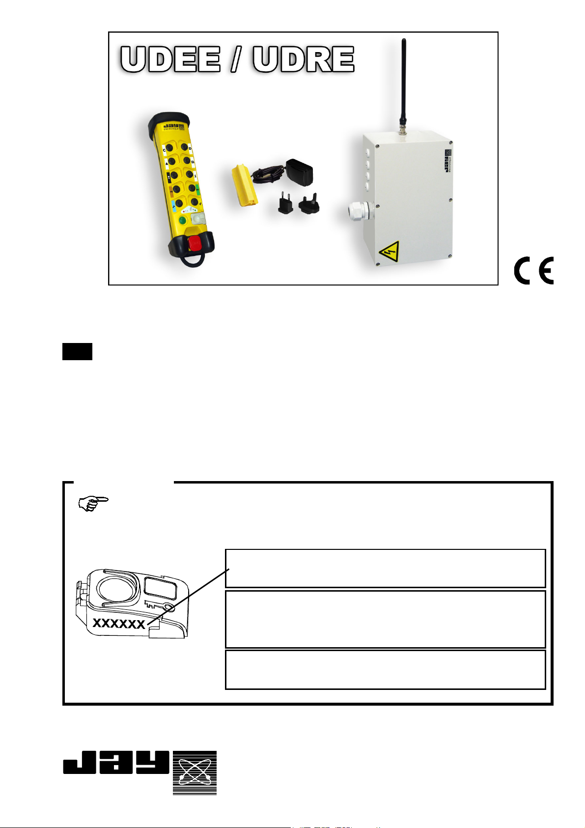
IMPORTANT
An identification number is engraved on the side of the electronic key.
Take a moment now to write down this number :
N° :
•Identity code number of associated receiver :
(electronic key of the transmitter UDEE)
électronique
•Equipment controlled :
PRELIMINARY
Document
Ref. doc :
332170A
revision02
Page 2

- TABLE OF CONTENTS -
General safety rules .......................................................................................... p. 4
1 Description of UDEE/UDREE radio remote control .......................................... p. 5
2 Installation ......................................................................................................... p. 6
2.1 Composition of the UDEE/UDRE Series and description of elements ............ p. 6
2.2 Unpacking the products ..................................................................................... p. 7
2.3 Product identification.......................................................................................... p. 8
2.3.1 UDEE transmitter ............................................................................................... p. 8
2.3.2 UDRE receiver ................................................................................................... p. 8
2.3.3 Accessories ....................................................................................................... p. 9
2.4 Delivery configuration ....................................................................................... p. 10
2.5 Installation recommendations ......................................................................... p. 11
2.5.1 Implementation of elements ............................................................................ p. 11
2.5.2 Marking of the controlled equipment ............................................................... p. 12
2.5.3 Wiring ............................................................................................................... p. 12
2.5.4 Interference suppression ................................................................................ p. 14
2.5.5 Electrical power supply protection ................................................................... p. 14
2.5.6 Minimum and maximum current of relay outputs ............................................ p. 14
2.5.7 Auxiliary control ................................................................................................. p. 14
2.5.8 Choice of operating radio frequency ................................................................ p. 14
2.6 UDEE transmitter function button labels ......................................................... p. 15
3 Commissioning .............................................................................................. p. 16
3.1 Precautions when commissioning ................................................................. p. 16
3.2 Periodic checks and checks performed following maintenance operations . p. 16
3.3 First startup of the radio remote control .......................................................... p. 17
3.4 Functioning block diagram .............................................................................. p. 18
3.5 Configuring the UDEE/UDRE radio remote control ........................................ p. 19
3.5.1 Procedure : «locking-unlocking» the electronic key (access to UDEE transmitter
programming) .................................................................................................. p. 20
3.5.2 Procedure : working frequency programming ................................................. p. 21
3.5.3 Procedure : «Dead man» function time programming ................................... p. 22
3.5.4 Procedure : «Copying electronic key identity code in the UDEE transmitter» p. 23
3.6 Configuring the receiver UDRE ....................................................................... p. 24
4 Use and operation ............................................................................................ p.25
4.1 Reminder of the general safety rules .............................................................. p. 25
4.2 Starting up the remote control .......................................................................... p. 26
4.3 Indicator light functions .................................................................................... p. 27
4.3.1 UDEE transmitter indicator lights .................................................................... p. 27
4.3.2 UDRE receiver indicator lights ......................................................................... p. 28
- 2 - UDEE / UDRE - 332170A revision02Fr En De PRELIMINARY
Page 3

5 Technical characteristics............................................................................... p. 29
5.1 Function button interlocking ............................................................................. p. 29
5.2 Correspondence between function buttons and relays .................................. p. 29
5.3 UDEE transmitter technical characteristics .................................................... p. 30
5.3.1 Identity code ..................................................................................................... p. 30
5.3.2 Electronic key ................................................................................................... p. 31
5.3.3 «Dead man» function ...................................................................................... p. 32
5.4 UDRE receiver technical characteristics ......................................................... p. 33
5.4.1 Connection to relays ........................................................................................ p. 34
5.4.2 Relay characteristics ........................................................................................ p. 34
5.4.3 Protection of receiver board and relays ........................................................... p. 36
5.5 UDB2 plug-in battery technical characteristics ............................................... p. 37
5.5.1 Battery pack storage precaution ...................................................................... p. 37
5.5.2 Precaution when inserting battery pack in transmitter unit ............................. p. 37
5.5.3 Display of battery pack charge state ................................................................ p. 38
6 Servicing .......................................................................................................... p. 39
7 Special functions ............................................................................................ p. 40
8 Warranty and FFC compliance ....................................................................... p. 40
Appendix :
A Receiver UDRE detailed internal view .......................................................... p. 42
B Transmitter UDEE detailed view ................................................................... p. 43
C Dimensions of elements ................................................................................. p. 44
D Wiring example (En. version) ......................................................................... p. 45
E Table of programmable radio frequencies .................................................... p. 46
F CE Declaration of conformity ......................................................................... p. 47
UDEE / UDRE - 332170A revision02 - 3 -FrEnDePRELIMINARY
Page 4

General safety rules
A radio remote control is considered as a machine control device and as a safety
component used to stop a machine as specified by the EEC Machinery Directive.
All applicable rules must therefore be observed to ensure safe, correct operation
of such devices.
- For maximum safety when using the radio remote control, we recommend that
the operator carefully follow the instructions provided in this manual.
- The operator must be appropriately trained and certified to operate machines
by radio remote control.
- The operator must have uninterrupted visibility of the manoeuvre which he
is performing. When the operator's direct field of view is inadequate, the lifting
machinery must be equipped with auxiliary devices to improve visibility.
When several machines are being moved simultaneously, the equipment must be
fitted out to limit to consequences of a possible collision.
- To avoid any risks of electrocution, don't open the receiver case when
powered.
- Never leave the transmitter lying around anywhere, in particular when it is
powered up.
- Never leave the radio control transmitter on the ground or on a metal surface. If
doing so becomes indispensable, press the stop palmswitch on the radio control.
- If several radio controls are used at the same site, different radio frequencies
should be used, spaced by at least two channels (for example, channels 5, 7, 9,
etc.). The more space there is between the chosen radio channels, the less the
risks of disturbance are.
- For safety reasons, remove the electronic key when not in use. Store it in a safe
and tracked down place.
- Do not forget to recharge the battery pack when discharged.
- In the event of a malfunction, immediately shut down the installation by pressing
the stop palmswitch on the transmitter and remove the electronic key.
- Service your equipment and perform all the periodic checks as may be required
by the intensity with which your equipment is used. Follow necessarily the
instructions of cleaning described in the chapter "Servicing".
- 4 - UDEE / UDRE - 332170A revision02Fr En De PRELIMINARY
Page 5

1- Description of UDEE/UDRE radio remote control
Thank you for choosing our UDEE/UDRE SeriesThank you for choosing our UDEE/UDRE Series
Thank you for choosing our UDEE/UDRE Series
Thank you for choosing our UDEE/UDRE SeriesThank you for choosing our UDEE/UDRE Series
industrial enhanced-safety radio remote control.industrial enhanced-safety radio remote control.
industrial enhanced-safety radio remote control.
industrial enhanced-safety radio remote control.industrial enhanced-safety radio remote control.
The UDEE/UDRE radio remote control is designed for remote control applications on
handling machines and for industrial equipment applications.
The radio remote control enables the operator to better focus on his work as it allows
him to choose his observation position which is only limited by safety considerations
(example: no one should be standing under a load).
The radio remote control completes and enhances the classic safety circuits (emergency
stop circuits).
Special attention has been given to ensure operator comfort through the following features :
z Ergonomic transmitters enabling one-hand control
z Control button accessibility
z Button touch sensitivity
z Identification of functions controlled
z Light-weight, compact transmitter
z Transmitter endurance, and fast charging battery pack
z Adaptability to all radio configurations of the environment by possibility for changing
frequency by a trained operator
z Mechanical protection of function buttons to avoid any unintentional action
z Transmitter carrying strap which hooks onto belt when unit is idle, or removable shoulder
strap (optional accessories)
To further enhance safety when using this equipment, technical solutions and innovative options are
also proposed :
z Radio remote control shutdown category 3 per EN954-1 and Hamming distance superior
or equal to 4 for each transmitted message
z Access is enabled by electronic key to an authorised operator only
z Memorisation of use of remote control by recording number of operations and durations
for each movement (option)
Easy maintenance :
z Customization entirely stored in electronic key
z Diagnostic aid indicator lights
z Parameter definition software (accessory)
Finally, the UDEE/UDRE radio remote controls fully satisfy the safety requirements of the current
applicable and draft standards and comply with the following European directives:
z Machinery Directive, shutdown category 3 per EN954-1
z RTTE : microwave equipment and telecommunication terminals (low voltage,
electromagnetic compatibility, radio-electric spectrum) ART conformity certificate
z American regulation FCC part 15
For any recommendations or questions concerning installation of the UDEE/UDRE remote control system,
))
)
))
contact us at our customer service department :
Tel : +33.(0)4.76.41.44.00
Fax: +33.(0)4.76.41.44.44
Email : support.technique.client@jay-electronique.fr
UDEE / UDRE - 332170A revision02 - 5 -FrEnDePRELIMINARY
Page 6
2- Installation
2.1- Composition of the UDEE/UDRE Series and description of
elements
The UDEE/UDRE Series comprises :
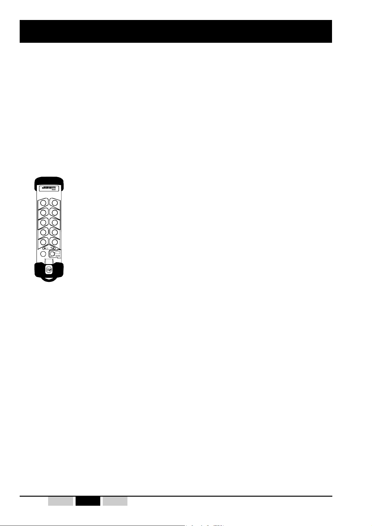
A transmitter : «UDEE» with radio communication :
élect roniq ue
10+2 button version
(10 function buttons + 1 «On/Horn» button + 1 «stop palmswitch button»)
A receiver «UDRE» which decodes the information generated by the remote control and
controls movements of the machines.
A battery pack «UDB2» (transmitter battery).
A battery pack charger «UBCU».
Accessories (strap, label kits, common wiring accessory etc...).
- 6 - UDEE / UDRE - 332170A revision02Fr En De PRELIMINARY
Page 7
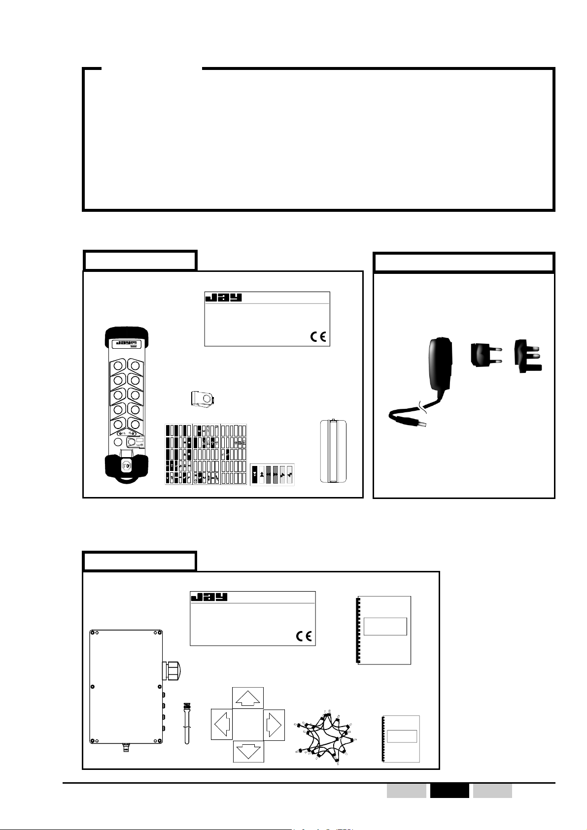
2.2- Unpacking the elements
IMPORTANT
When unpacking the products, be sure to :
- Write down the electronic key number on the cover page of this manual.
This number will allow you to order a new, identical electronic key defined with
your parameters.
- Put the battery pack on load for 14 hours minimum before a first use.
1st package
Transmitter
UDEE
électronique
electronic key
D
U
O
P
W
N
N
S
O
O
U
R
T
T
H
H
N
S
O
U
R
D
D
(1) = mounted on transmitter
(1)
R
F
R
S
E
O
L
I
H
V
R
E
E
W
G
U
F
R
A
H
N
S
R
T
E
D
T
T
W
E
+
-
E
A
R
R
S
S
P
P
T
T
M
M
O
1•12
U
E
•
12
E
S
S
T
T
1
•2•3•
2
1+2
•
Descriptive label
électronique
Ref :
UDE . . . . .
Freq : .... .. ....MHz
Serie : .../... .
Date : .. / ..
ON
•
OFF
1 2 3
GATE
7 8 9
123
34
12
3+4
1+2
34
43
3+4
4
3
IP65
4
5 6
label
kits
Battery pack
UDB2
2nd package
Battery pack charger
(for charging the UDB2 battery pack)
UBCU
(1)
110-230VAC/12VDC
with european and
english plugs
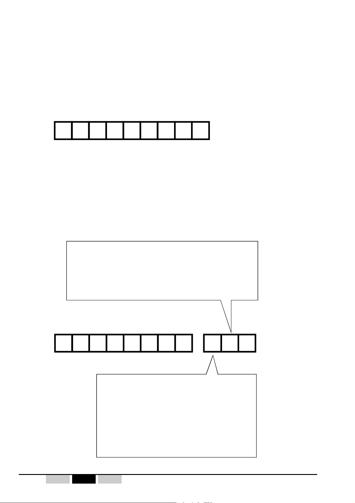
3rd package
Descriptive label
Receiver
UDRE
Ref :
UDR . . . . . - . . .
Freq : .... .. ....MHz
Serie : .../... . Alim : .....V..
électronique
Date : .. / ..
IP65
4 colored directional
arrows
Antenna
UDEE / UDRE - 332170A revision02 - 7 -FrEnDePRELIMINARY
F 38330 Montbonnot
Code : . . . .
common wiring
accessory
Technical manual
Technical manual
only for additional
options
Page 8
2.3- Product identification
(according to sales reference)
2.3.1- Transmitter UDEE
UDEE22222
2.3.2- Receiver UDRE
Programming of button - relay correspondence :
Number of relays controlled by BPDV (double speed
pushbutton)
= 3 relays
1
= 4 relays
2
= special (equipment definition covered by a customization
x
data sheet)
UDR
ECB
Programming of transmitter button interlocking :
= no interlocking
0
= interlocking button n°1-n°2, n°-n°4, n°5-n°6
1
with output relays set to OFF
= interlocking button n°1-n°2, n°-n°4, n°5-n°6
2
with priority on left button
= interlocking button n°1-n°2, n°-n°4, n°5-n°6
3
with priority on right button
= special (equipment definition covered by a
x
customization data sheet)
0
-
01
- 8 - UDEE / UDRE - 332170A revision02Fr En De PRELIMINARY
Page 9
Reference Description
UBCU
Charger for battery pack, 110-230VAC/12VDC with european and english plugs
UDB2
(1)
Transmi tter plug-in ba tter y pack
UDC1
Wall br acket f or stowing and batt e ry pack chargi ng when id le
UDWE2 2 X
(1)
Programmed electronic key (electronic key number to be supplied)
UDP1
Bel t fastenin g cli p
UWE 102
Removable shoulder strap
UWE 303
Protective case for transmitter 10+2 button version
UWE 202
(2)
Kit of 6 colored labels "movements" for double speed pushbuttons (2 steps)
UWE 205
Kit of 48 white blank labels for cutomized marking
UWE 207
(2)
Kit of 90 white/black labels "movements, special functions and customizati on" for
switches and pushbuttons
Reference Description
VUB984
BNC straight antenna, 1/2 wave in 911-918MHz
VUB105
2m extension for antenna + non insulated bracket BNC
VUB125
5m extension for antenna + non insulated bracket BNC
VUB131
10m extension for antenna + non insul at e d bracket BNC
UWE 001
2 ways dire cti onal colored ar rows for trav el ling crane
UWE 002
(1)
4 ways dire cti onal colored ar rows for trav el ling crane
UDWR38
Fastening Kit for receivers by magnetic contacts
UDWR12
(1)
Common wiring accessory
UDWR13
24-pin plug-in connector + 2m cable
UDWR14
16-pin plug-in connector + 2m cable
UDWR23
UDWR13 cabling realization in UDRE receiver
UDWR24
UDWR14 cabling realization in UDRE receiver
UDWR32
Serial li nk boa rd (kit UDW R36 sof twar e + cabl e to be ordered separately)
UDWR36
PC "DialogUD" Software (CD-ROM+ computer PC/ receiver UDRE cable)
2.3.3- Accessories
For UDEE transmitter
For UDRE receiver
(1)= 1 accessory supplied with product
(2)= Label kits supplied systematically with transmitter
UDEE / UDRE - 332170A revision02 - 9 -FrEnDePRELIMINARY
Page 10

2.4- Delivery configuration
• Radio channel number :
- Programmed with radio channel number 01 (911,800MHz)
• Duration of the temporization for the "Dead Man" function (automatic shutdown of
remote control in case of prolonged non-use) :
- Programmed for 4 mn
• Button / relay configuration and button interlocking:
- According to product definition with order (receiver reference) or special (equipment
definition covered by a customization data sheet).
• Locking of the UDEE transmitter electronic key :
(access to UDEE transmitter programming)
- The transmitter is supplied with an "unlocked" electronic key, programmings : Radio channel
and "Dead man" function duration can be directly modified by a trained operator (see
programming procedures on chapter «transmitter configuration»).
- 10 - UDEE / UDRE - 332170A revision02Fr En De PRELIMINARY
Page 11
2.5- Installation recommendations
Experience shows that the functional efficiency of the system basically depends on the quality of
the installation :
- Implementation of elements,
- Marking of the controlled equipment,
- Wiring quality of UDRE receiver,
- Interference suppression,
- Electrical power supply protection,
- Minimum and maximum current of relay outputs,
- Choice of operating frequency.
2.5.1- Implementation of elements
))
)
))
Receiver position
The remote control receiver UDRE should be mounted as close as possible to the control
cabinet, vertical with respect to the machine structure. The receiver should be sheltered from
shocks and weather.
The antenna should be as far as possible from the class 3 cables and power components
(power supply, motor, variable speed drive, etc.) while remaining within an area favorable to
radio reception :
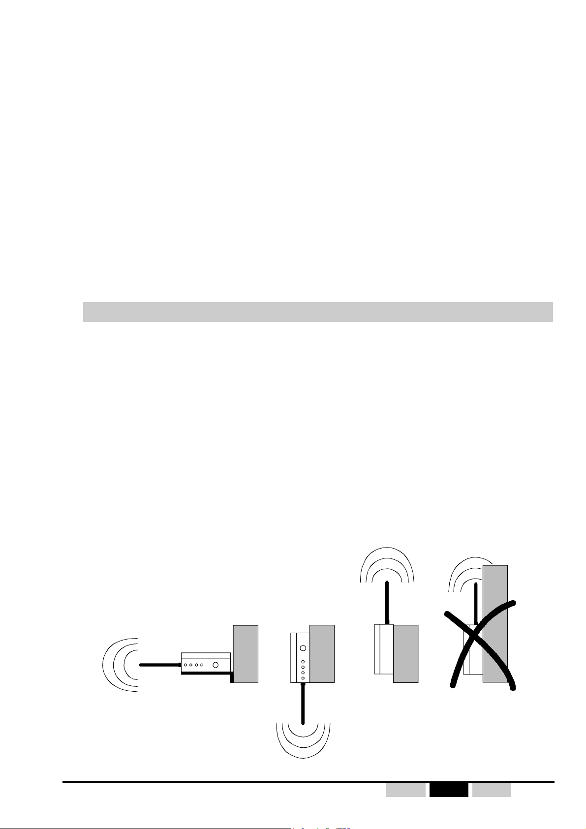
z The antenna should be located at a height, above the operator using the transmitter UDEE.
z The antenna must be directed toward the transmitter working areas (downward with a hoist).
z The antenna orientation is indicated in the figure below :
Element dimensions are available for consultation in Appendix C
No metal object which could create a screen should be located between the operator and
the antenna.
Good
UDRE
Metal
UDEE / UDRE - 332170A revision02 - 11 -FrEnDePRELIMINARY
Good
Metal
Good
Metal
Metal
Wrong
Page 12
2.5.2- Marking of the controlled equipment,
490 mm
180
mm
If there are several equipment fitted with similar radio remote control systems working in the
same neighbourhood (e.g. in a plant), each transmitter shall carry a clear indication which
tells the equipment driver which equipment is controlled by the transmitter in question.
In this respect, signalling arrows are available as an accessory.
Place the different arrows on the equipment to be controlled so that each arrow colour
corresponds to that on the associated transmitter control button.
The direction of movement of control buttons shall whenever possible be consistent with
equipment motion. Symbols shall be fixed in such positions that there is a clear and unambiguous
relationship between the action on buttons in the control station and the corresponding direction
of motion.
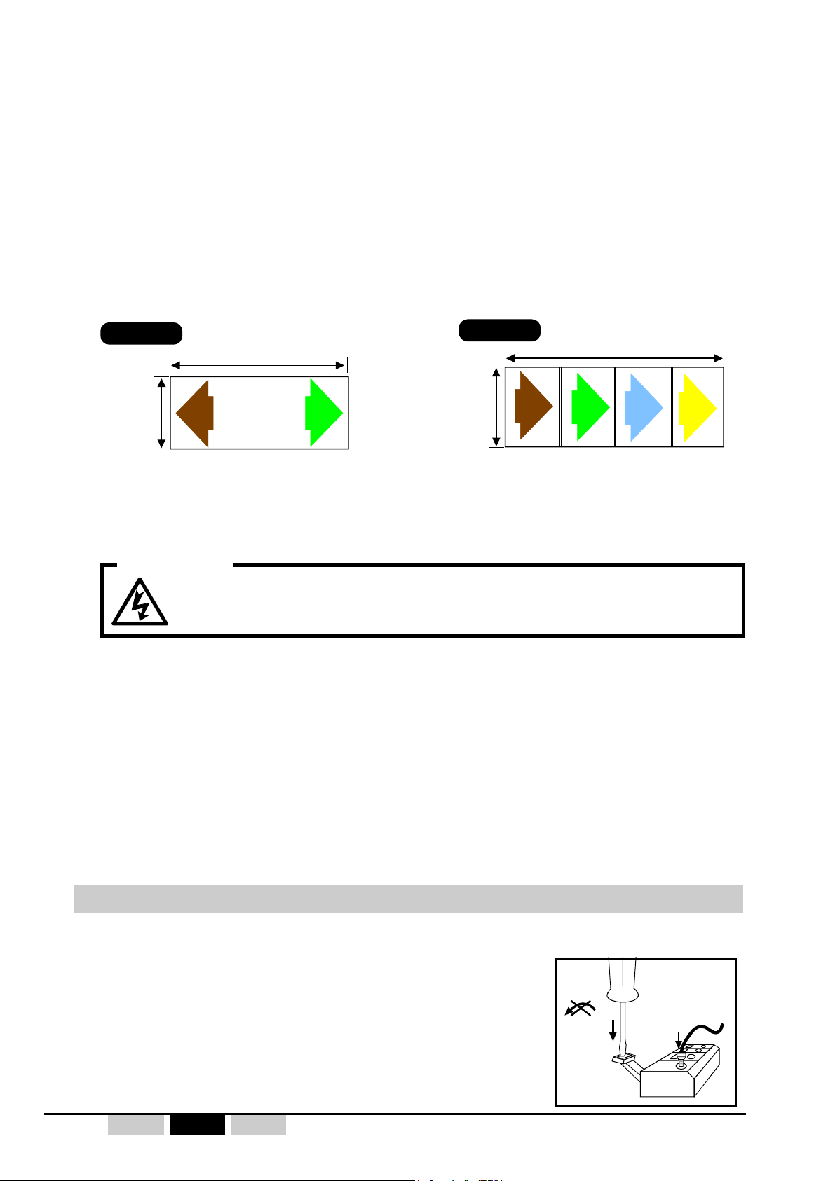
The arrows are available in the following versions:
Reference :
UWE001
160
mm
Reference :
2 ways directional self-adhesive
color arrows
400 mm
brown green brown green blue yellow
UWE002
4 ways directional self-adhesive
color arrows
(independent arrows)
2.5.3- Wiring
WARNING
To avoid any risks of electrocution, do not open the receiver case
when powered.
Important :
Do not place cables of different classes side by side.
A minimum space (20 cm) should be observed between the different classes :
- Class 1 : Radio, antenna cable (case of an antenna extension).
- Class 2 : Mains for power supply of various units.
- Class 3 : Power control for motors, variable speed drive, etc...
Ideally, each cable class should be run through a cable path specific to the class. If only one
cable path is available, cables of different classes should be separated as much as possible.
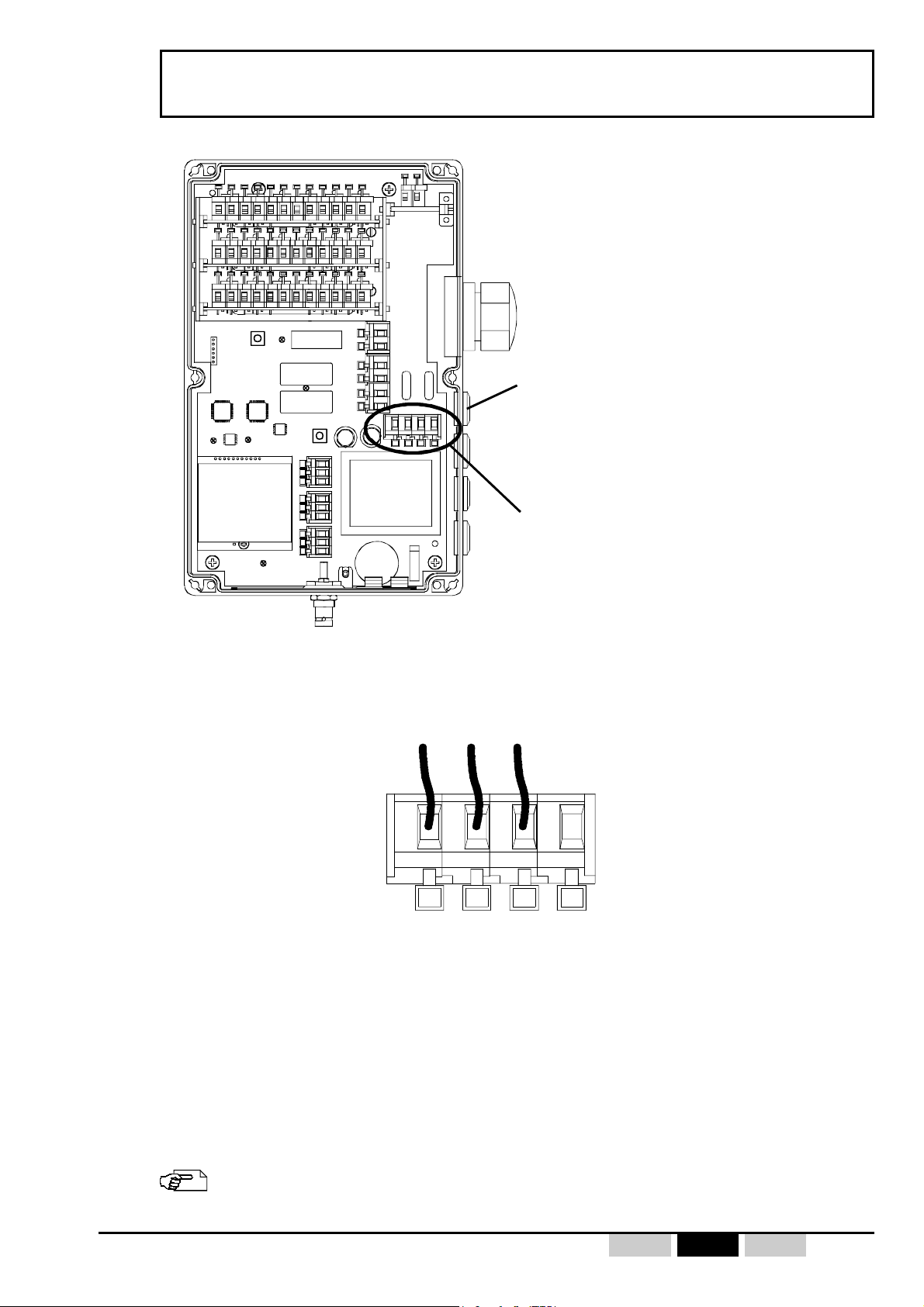
Wiring the receiver UDRE
If flexible stranded wire is used, crimped terminations should be used to avoid false contacts
and short circuits.
To open the connection terminal strips:
- Vertically push the screwdriver (flat tip screwdriver of 1.5 to
3 mm width) on the lever,
- Exercise a moderated pressure up to opening the terminal
- Insert the wire,
- Remove the screwdriver.
- 12 - UDEE / UDRE - 332170A revision02Fr En De PRELIMINARY
Page 13
2223 21 20
UDRECB00 - **1
115/230 VAC
115VAC
230VAC
N
Caution: The electrical connections should be made such that when the main switch
is off, the UDEE/UDRE remote control receiver is also deactivated.
A
B
C
RK
RS1
RS2
F1
Advised way for power supply cable
F2
Power supply terminals strips
UDR receiver reference :
For the wiring and to determine the correspondence between the action on a function button
and the relay controlled, refer to the configuration table supplied with the receiver (label on
housing cover) and appendix A.
UDEE / UDRE - 332170A revision02 - 13 -FrEnDePRELIMINARY
See wiring example in appendix D
Page 14

2.5.4- Interference suppression
In the event of inductive loads on the relay outputs (contactor coils, solenoid valves or electrobrakes), interference suppression devices such as capacitors, RC circuits, diodes, etc. must
be placed directly at the terminals of the controlled components using the shortest possible
connections.
2.5.5- Electrical power supply protection
Protection against overcurrents (EN60204-1 § 7.2) resulting from overvoltages.
A fuse or other protection device should be provided in the power supply circuit of the receiver
(see wiring diagram for standard assemblies, item F in appendix D). The assigned current is
defined in the table in § «UDRE receiver technical characteristics».
2.5.6- Minimum and maximum current of relay outputs
Be sure not to exceed the minimum and maximum characteristics specified in § «UDRE
receiver technical characteristics» by installing, if necessary, an additional load or intermediate
relays (auxiliary contacts in electrical cabinet for power control, for example).
2.5.7- Auxiliary control
Measures should be taken to ensure, that when the radio control is not in service, another
control system can be used to ensure the safety of the operator and the manipulated load.
2.5.8- Choice of operating radio frequency
The 64 radio channels in 911-918MHz of the UDEE/UDRE provide a broad range of choices
among the available frequencies. To ensure good operating quality, it is important that the
radio channel used be free (as well as the preceding and the following one) throughout the
area in which the machine will be controlled.
If several radio remote controls are operating on the same site, frequencies spaced by at least
two channels (for example: 5, 7, 9 …) should be used and, if necessary, a frequency plan
should be drawn up, specifying the various machines controlled and their working frequency.
- 14 - UDEE / UDRE - 332170A revision02Fr En De PRELIMINARY
Page 15
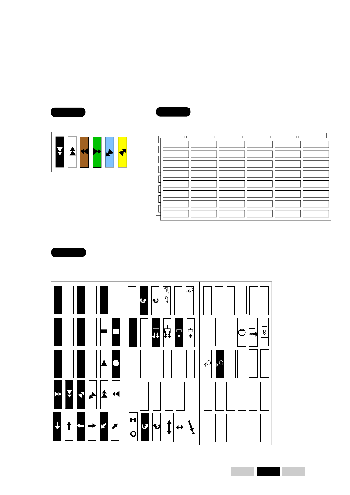
2.6- UDEE transmitter function button labels
The various button functions are identified by means of adhesive labels placed in the recesses
provided in the transmitter unit envelope at each button location.
The labels are supplied in the form of sheets with the various labels you will need for your application.
Simply choose the labels corresponding to your configuration.
2 label kits are systematically supplied with UDEE transmitter: UWE202 and UWE207.
Reference :
UWE202
Kit of 6 colored labels, «movements»,
for double speed pushbuttons (2 steps)
brownwhiteblack green blue yellow
Reference :
Reference :
UWE205
Kit of 48 white blank labels, «customization» + 48 transparent protecting labels.
UWE207
Kit of 90 white/black labels, «movements, special functions and customization» for switches and
pushbuttons (with 16 labels for personalized marking with indelible felt-tip)
D
O
W
N
S
O
U
T
H
S
U
D
N
O
H
N
O
U
P
R
T
R
D
W
E
S
T
O
U
E
S
T
F
R
E
O
V
R
E
W
R
A
R
S
D
E
E
A
S
T
E
S
R
G
H
T
S
I
H
U
N
T
+
-
R
R
P
P
M
M
L
E
F
T
1•12
•
12
ON
OFF
•
1 2 3
GATE
4
5 6
7 8 9
34
123
12
1+2
3+4
T
1
2
1+2
•
•2•3•
34
43
3+4
4
3
UDEE / UDRE - 332170A revision02 - 15 -FrEnDePRELIMINARY
Page 16

3- Commissioning
3.1- Precautions when commissioning
• The installer must :
- ensure that the transmitter and receiver identity code and radio channel match correctly,
- ensure that the radio channel chosen corresponds to the frequency plan set up for the site,
- perform a final check to verify that the desired Button-Relay correspondence is in place.
• During the previous check, the installer must check that when the "On/Horn" button is pressed
on startup, only the function relays assigned to the rotary button selections are in the "ON"
state.
• Verify the priority general shutdown mode (remote control in operation and radio link
established)::
Active stop : When the stop palmswitch button on the transmitter is pressed, the receiver
safety relays (RS1 and RS2) should instantaneously change state.
Passive stop : When the electronic key is removed from the transmitter in operation, the
receiver safety relays (RS1 and RS2) should change state within two seconds
max.
• "Dead man" function duration :
Check the effective duration of the "Dead man" function (automatic shutdown of transmitter) :
Start up the remote control and leave it without activating any control. Record the time after
which the receiver safety relays (RS1 and RS2) are deenergized and check that this duration
corresponds to the standard duration supplied (4min.) or the duration specified on order
(special programming, see customisation sheet), or to the new duration defined by a trained
and authorized operator in accordance with the procedure described in chapter «transmitter
configuration».
• Radio range limits :
Evaluate the range limit of the transmitter/receiver assembly (by moving up to the range limit).
• Special function: masking of certain function buttons :
If button masks are included in the electronic key, check that they properly correspond to the
application for which they have been provided.
3.2- Periodic checks and checks performed following
maintenance operations
In addition to the commissioning checks which should be performed, also check :
- That the ergonomic features of the transmitter unit have been preserved, such as: pressure on
function buttons, correct rotation of rotary switches, correct functionning of emergency stop
button, etc.
- Response time of commands between transmission of a command and resulting movement.
- 16 - UDEE / UDRE - 332170A revision02Fr En De PRELIMINARY
Page 17

3.3- First radio remote control startup
1- Switch ON the UDRE receiver.
2- Plug the UDB2 battery pack into UDEE transmitter housing.
(Take care that UDB2 battery pack is loaded and is well
connected to UDEE transmitter back.)
3- Install the electronic key on the transmitter or take care of
its presence on UDE transmitter.
4- Copy electronic key identity code to UDEE transmitter
memory, see procedure on § 3.5.4.
5- Unlock the transmitter stop palmswitch button.
UDEE
transmitter
UDB2
battery pack
électronique
electronic
key
6- Press the green «On/Horn» button until the receiver is
started up (safety relays are activated).
7- Use the radio remote control to control the equipment.
To stop the radio remote control :
press the UDEE transmitter stop palmswitch button.
NB : if this procedure is not observed the transmitter indicates an error with the red and green
indicator light :
- «3 flashes error type» (The green and red leds flash 3 times, mark a break, then flash 3
times etc.) : resume identity code copy procedure described in § 3.5.3.
- «5 flashes error type» (The green and red leds flash 5 times, mark a break, then flash 5
times etc.) : Stop or startup error (make sure that the pack battery is correctly inserted in the
transmitter housing and resume the radio remote control startup procedure).
See startup block diagram on next page
UDEE / UDRE - 332170A revision02 - 17 -FrEnDePRELIMINARY
Page 18

3.4- Functioning block diagram
Or
Passive stop if "Dead Man"
duration is exceeded (1)
or
Battery pack is
disconnected/discharged (2)
or
Electronic key removed from
Active stop by pressing
stop palmswitch button
UDE transmitter in operation
(1) "Dead Man" duration
T
(2)
Last action on
function pushbutton
UTILISATION
Green "On/Horn"
button pressed
90% > Charge > 10 % Charge < 10 %
Battery pack charge > 90 %
Charge < 10 %
90% > Battery pack charge > 10%
Passive stop : battery pack is discharged
Battery pack charge < 10%
Active
Red stop palmswitch
unlocked,
UDEE transmitter
powered up
- 18 - UDEE / UDRE - 332170A revision02Fr En De PRELIMINARY
Standby
3 states
OFF
of UDEE
UDRE receiver RS1 and
RS2 safety relays
UDEE transmitter
green indicator light
3 states of red
indicator light of UDEE
(battery pack charge
state)
Page 19

n°1 n°2
n°5
n°6
n°3 n°4
3.5- UDEE/UDRE system configuration and parameter setting
The following parameters are configurable from the UDEE transmitter unit :
• Transmit frequency (radio channel number selection).
• The "Dead man" function duration (01 to 98 minutes and infinite).
• Copy of electronic key identity code to transmitter memory.
These configuration operations use procedures implementing buttons n°1, n°2, n°3, stop plamswitch
and "On/Horn" without having to open the transmitter or the receiver.
By a specific operating mode, the person in charge of the equipment can lock or unlock the
access to the programming of Transmit frequency and "Dead man" function duration by locking or
unlockin the electronic key (see §3.5.1).
Programming
n°3
button
Programming
button
n°1
"On/Horn" button
Programming
n°2
button
stop plamswitch button
UDEE / UDRE - 332170A revision02 - 19 -FrEnDePRELIMINARY
Page 20

3.5.1 Procedure: "Locking-unlocking" the electronic key
(access to programming of transmitter UDEE)
The transmit radio frequency and the "Dead man" function duration are saved into the electronic
key. Procedure below enables authorization (electronic key unlocked) or prohibition (electronic
key locked) of any modification of these 2 parameters.
1- Switch off the UDRE receiver.
2- Insert the electronic key in the UDEE transmitter unit.
3- Holding buttons n°1, n°2 and n°3 pressed, unlock the stop palmswitch button (fig.1).
4- Release the buttons.
Indicator lights statuses:
- electronic key locked : red indicator light on, green indicator light off.
- electronic key unlocked : red and green indicator lights on.
5- Select «locked» or «unlocked» by pressing button n°2; the selected mode is shown by the
indicator lights (fig.2&3).
6- Validate the selected mode by pressing the "On/Horn" button (fig.4).
7- The UDEE transmitter saves the new mode in the electronic key and switches off the indicator
lights.
8- Exit the "locking - unlocking" configuration mode by pressing the stop palmswitch button (fig.6).
Remark: If an operator attempts to program the frequency or the "dead man" function duration
with the electronic key locked, the UDEE transmitter will indicate an error by its
indicator lights (red and green) which will flash in alternation.
Unlocking
the
electronic
key
Fig.1
Fig.2
Locking
the
electronic
key
Fig.3
DATA
Fig.4
Fig.5 Fig.6
- 20 - UDEE / UDRE - 332170A revision02Fr En De PRELIMINARY
Page 21

3.5.2 Procedure : working radio frequency channel programming
+1
+10
DATA
1- Switch on the UDRE receiver.
2- Insert the electronic key in the UDEE transmitter unit.
3- Holding buttons n°1 and n°2 pressed, unlock the stop palmswitch on the transmitter (fig.1).
The radio channel already selected is indicated by two flashing indicator lights on the transmitter
which represent the tens (red) and units (green).
If transmitter red and green indictor lights flash in alternation :
The electronic key is locked. Press the stop palmswitch button and follow procedure described
on chapter §3.5.1. Start again this procedure at point Nb.3.
4- Select the new channel using buttons n°1 and n°2 (fig.2&3).
Press button n°1 to increment the tens and button n°2 to increment the units.
During these operations, the newly selected channel is displayed by the 2 indicator lights on the
transmitter which flash accordingly.
5- Once the desired channel is selected (between 01 and 64 for 911-918MHZ bands), press the "On/
Horn" button to validate your selection (fig.4).
Briefly pressing "On/Horn" button : the transmitter sends the selected radio channel number to
the receiver and saves its new working radio channel (fig. 5).
By pressing and holding the "On/Horn" button (3 seconds) : the transmitter sends the selected
channel number to the receiver (on each of the radio link channels between 01 to 64 for 911918MHZ bands) and saves its new working channel. Wait until the transmitter indicator lights
no longer flash (around 30 seconds) (fig. 5)
(this longer procedure is preferable and should be performed when you are not familiar with the initial
working channel of the receiver).
6- Exit the "frequency" programming mode by pressing the stop palmswitch button (fig.6).
7- Check that the UDRE receiver has changed channel by performing the startup procedure.
Fig.1 Fig.2
électronique
Fig.4
UDEE / UDRE - 332170A revision02 - 21 -FrEnDePRELIMINARY
Fig.3
Fig.5 Fig.6
Page 22

3.5.3 Procedure : "Dead man" function time programming
(Automatic shutdown of transmitter UDEE)
1- Switch off the UDRE receiver.
2- Insert the electronic key in the UDEE transmitter unit.
3- Holding buttons n°1 and n°3 pressed, unlock the stop palmswitch button on the transmitter
(fig.1).
The "dead man" time is displayed by two flashing indicator lights on the transmitter representing
the tens (red) and the units (green) of the number of minutes.
If transmitter red and green indictor lights flash in alternation :
The electronic key is locked. Press the stop palmswitch button and follow procedure described
on chapter §3.5.1. Start again this procedure at point Nb.3.
4- Select the new time using buttons n°1 and n°2 (fig.2&3).
Press button n°1 to increment the tens and button n°2 to increment the units.
During these operations, the new time selected is displayed by the two indicator lights on the
transmitter.
5- Once you have selected the desired "dead man" time (between 01 and 99), press the «On/
Horn» button to validate your selection (fig.4).
Caution: No. 99 corresponds to an infinite "dead man" time
> This function is then deactivated and forgetting to switch off the transmitter (by
pressing the stop palmswitch button) will result in complete discharge of the
battery pack.
6- Exit the "dead man" time programming mode by pressing the stop palmswitch button (fig.6).
+10
Fig.1
mn
Fig.2 Fig.3
+1
mn
DATA
Fig.4
Fig.5
- 22 - UDEE / UDRE - 332170A revision02Fr En De PRELIMINARY
Fig.6
Page 23

DATA
3.5.4 Procedure: "Copying electronic key identity code to UDEE transmitter
memory"
Apply this procedure when :
- starting the radio remote control for the first time
- using a maintenance transmitter
- changing the electronic key
Reminder :
To use the UDEE/UDRE radio remote control system, the identity code contained in the transmitter
memory must match the identity code in the electronic key which is itself identical to that of the
receiver.
If a maintenance transmitter is used or if you change electronic key, the information contained in the
electronic key must be copied in the UDEE transmitter memory.
Conditions for using this procedure :
The configuration of the backup transmitter buttons must be identical to that described in the
electronic key (or the original transmitter).
1- Switch off the UDRE receiver
2- Insert the electronic key in the UDEE transmitter unit.
3- While holding buttons n°2 and n°3 pressed, unlock the transmitter emergency stop button (fig.
1): the 2 indicator lights on the transmitter will flash rapidly.
4- Press the "On/Horn" button to perform automatic programming of the identity code: the two
indicator lights on the transmitter go off (fig. 2).
5- The "identity code" information is copied from the electronic key to the transmitter memory (fig.
3).
6- Exit the programming mode by pressing the stop palmswitch button (fig.4).
Fig.1
electronic key
memory
Fig.2 Fig.4
Fig.3
UDE
transmitter
memory
UDEE / UDRE - 332170A revision02 - 23 -FrEnDePRELIMINARY
Page 24

3.6- UDRE receiver configuration
The following parameters can be configured on the receiver :
• Transmitter button interlockings :
Factory configured or using a PC via serial link option (ref.:UDWR32) with PC
software DialogUD (ref.:UDWR36).
• Transmitter buttons / receiver function relays correspondence :
Factory configured or using a PC via serial link option (ref.:UDWR32) with PC
software DialogUD (ref.:UDWR36).
• Transmit radio frequency :
The radio reception frequency (channel No.) can be programmed in two ways:
• By the transmitter matched to the receiver implementing the transmitter
frequency programming procedure, see §3.5.2.
• By using a PC via serial link option (ref.:UDWR32) with PC software DialogUD
(ref.:UDWR36).
The receiver reception frequency (channel No.) can be read :
• By using a PC via serial link option (ref.:UDWR32) with PC software DialogUD
(ref.:UDWR36).
- 24 - UDEE / UDRE - 332170A revision02Fr En De PRELIMINARY
Page 25

4- Use and operation
4.1- Reminder : General safety rules
A radio remote control is considered as a machine control device and as a safety
component used to stop a machine as specified by the EEC Machinery Directive.
All applicable rules must therefore be observed to ensure safe, correct operation
of such devices.
- For maximum safety when using the radio remote control, we recommend that the
operator carefully follow the instructions provided in this manual.
- The operator must be appropriately trained and certified to operate machines by
radio remote control.
- The operator must have uninterrupted visibility of the manoeuvre which he is
performing. When the operator's direct field of view is inadequate, the lifting machinery
must be equipped with auxiliary devices to improve visibility.
When several machines are being moved simultaneously, the equipment must be
fitted out to limit to consequences of a possible collision.
- To avoid any risks of electrocution, don't open the receiver case when powered.
- Never leave the transmitter lying around anywhere, in particular when it is powered
up.
- Never leave the radio control transmitter on the ground or on a metal surface. If doing
so becomes indispensable, press the stop palmswitch on the radio control.
- If several radio controls are used at the same site, different radio frequencies should
be used, spaced by at least two channels (for example, channels 5, 7, 9, etc.). The
more space there is between the chosen radio channels, the less the risks of
disturbance are.
- For safety reasons, remove the electronic key when not in use. Store it in a safe and
tracked down place.
- Do not forget to recharge the battery pack when discharged.
- In the event of a malfunction, immediately shut down the installation by pressing the
stop palmswitch on the transmitter and remove the electronic key.
- Service your equipment and perform all the periodic checks as may be required by
the intensity with which your equipment is used. Follow necessarily the instructions of
cleaning described in the chapter "Servicing".
UDEE / UDRE - 332170A revision02 - 25 -FrEnDePRELIMINARY
Page 26

4.2- Radio remote control start up
1- Switch ON the UDRE receiver.
2- Plug the UDB2 battery pack into UDEE transmitter housing.
(Take care that UDB2 battery pack is loaded and is well
connected to UDEE transmitter back.)
UDEE
transmitter
UDB2
battery pack
électronique
3- Install the electronic key on the transmitter or take care of
its presence on UDE transmitter.
4- Unlock the transmitter stop palmswitch button.
5- Press the green «On/Horn» button until the receiver is
started up.
electronic
key
6- Use the radio remote control to control the equipment.
To stop the radio remote control :
press the UDEE transmitter stop palmswitch button.
NB : If during this procedure, both UDEE transmitter indicator light begin flashing,
please contact the technical person in charge of the installation.
- 26 - UDEE / UDRE - 332170A revision02Fr En De PRELIMINARY
Page 27

Transmitter state
(The trans mitter stop
pa lms witc h is unlocke d)
Red
indi cator l ight
Green
indi cator light
Possib le causes of failure Possib le re medies
Before or after
"O n/ ho rn" bu tto n is
pressed
- Battery pack is discharged or disconnected
- Internal electronic failure
- Check battery pack load
or
- Contact the technical person in charge of
the installation
Before or after
"O n/ ho rn" bu tto n is
pressed
- Electronic key is not connected to
trans mitter
- Bad connection of the electronic key
- Electr on ic k ey failu re
- Internal electronic failure
- Install electronic key on tranmitter before
powering up the transmitter
or
- Contact the technical person in charge of
the installation
Before or after
"O n/ ho rn" bu tto n is
pressed
- Access to the transmitter programming is
prohibited (the electronic key is locked)
- If the transmit frequency or "Dead man"
function duration must be changed, the
electronic key must be unlocked. Follow
procedure described in §3.5.1.
or
- Contact the technical person in charge of
the installation
Before "On/horn"
button is pressed
- The transmitter identity code is different
from that contained in the electronic key
- Internal electronic failure
- Reprogramming is required, see
procedure in §3.5.4.
or
- Contact the technical person in charge of
the installation
Before or after
"O n/ ho rn" bu tto n is
pressed
- The button configuration is different from
that contained in the electronic and the
physical configuration on the transmitter
- One or several function buttons are
defective
- Internal electronic failure
- Contact the technical person in charge of
the installation
Before "On/horn"
button is pressed
- Micro power cuts due to a bad battery pack
connection
- Internal electronic failure
- Check that battery pa ck is correctly
inserted in transmitter housing
or
- Contact the technical person in charge of
the installation
Before "On/horn"
button is pressed
- Internal electronic failure
- Contact the technical person in charge of
the installation
Before "On/horn"
button is pressed
- Internal electronic failure
- Contact the technical person in charge of
the installation
Before "On/horn"
button is pressed
- Internal electronic failure
- Contact the technical person in charge of
the installation
Transmitter state
(stop pal mswitch button
unlock ed)
Red
indi cator l ight
Green
indi cator light
Before "On/horn"
button is pressed
OFF ON
Before "On/horn"
button is pressed
Flashes SLOW ON
Before "On/horn"
button is pressed
Flashes FAST ON
After "O n/horn" button
is pressed
OFF Flashe s
After "O n/horn" button
is pressed
Flashes FAST Flashes
8 flashes
Error messages
continuously OFF
continuously ON
3 flashes
4 flashes
flash in a alternative way
5 flashes
6 flashes
7 flashes
Battery pack charge level
Funct ion or corres ponding message
Radio transmission
Battery pack charge < or = LOW BATT level
Battery pack charge > 90%
90% > Battery pack charge > LOW BATT level
Battery pack charge < or = LOW BATT level
Radio transmission
Battery pack charge > LOW BATT level
4.3- Product indicator lights function
4.3.1 UDEE transmitter indicator lights
RED
indicator
light
GREEN
indicator
light
«LOW BATT level» = low battery (battery pack charge level lower than 10%), the battery pack must be reloaded.
UDEE / UDRE - 332170A revision02 - 27 -FrEnDePRELIMINARY
Page 28

RK
RS1
RS2
F1
F2
A
B
C
g
4.3.2 UDRE indicator lights
Function relay indicator lights (red)
«Horn» relay indicator light (red)
«RS1 and RS2» safety relays indicator lights (red)
Microprocessor n°1 indicator light (red)
Microprocessor n°2 indicator light (green)
Power supply indicator light (red)
Name and col or o f
indicator li
Mi cropro cessor n°1
indicator light
(RED)
Mi cropro cessor n°2
indicator light
(GREEN)
"Horn" relay ind.light
(RED)
Power supply ind.l ight
(RED)
Safety relays ind.light
(RED)
Function relays ind.light
(RED)
ht
Mode Indication Message Status
No message reception OFF
Normal
Serial
link
Normal
Serial
link
All Ind ic ates "Horn " r elay s tate
All
All I ndicates saf ety r elays stat e
All
Indicates validity
of identity code
"R S2 32 Mode" The rec eiver pr ogramming is in pr og ress ON
Indicates radio
reception quality
"RS232 Mode" OFF
Indicates receiver power
supply state
Indicates each function relays
state
Message reception with correct identity code OFF
Mess age r ecept ion with wrong i denti ty code Regu lar flashes
No radio message reception OFF
Poor radio reception Flashing
Good radio reception ON
Not activated (OFF) OFF
activated (ON) ON
Receiver switched OFF OFF
Receiver switched ON ON
Not activated (OFF) OFF
activated (ON) ON
Not activated (OFF) OFF
activated (ON) ON
Error messages
Micro n° 1
indicator light
- RED -
OFF
(Mainboard power supplied but power
supply red indicator light remains OFF)
2 flashes
3 flashes
4 flashes
5 flashes
6 flashes
7 flashes
Micro n° 2
indicator light
- GREEN -
Possible causes of failure Possible remedies
- Melted fuses
- Wrong power supply wiring
- Internal electronic failure
- Internal electronic failure
- 28 - UDEE / UDRE - 332170A revision02Fr En De PRELIMINARY
- Check fuse state and calibre
- Check power supply wiring diagram according to
receiver model
or
- Contact the technical person in charge of the
installation
- Contact the technical person in charge of the
installation
Page 29

1st button of
interlocked pair
1nd button of
interlocked pair
Acronym
Button n°1 Button n°2 B1-B2
Button n°1 Button n°3 B1-B3
Button n°1 Button n°4 B1-B4
Button n°2 Button n°3 B2-B3
Button n°2 Button n°4 B2-B4
Button n°3 Button n°4 B3-B4
Button n°3 Button n°5 B3-B5
Button n°4 Button n°6 B4-B6
Button n°5 Button n°6 B5-B6
Button n°7 Button n°8 B7-B8
Button n°7 Button n°10 B7-B10
Button n°8 Button n°9 B8-B9
Button n°9 Button n°10 B9-B10
5- Technical data
5.1- Function button interlockings
The following function button interlocking configurations are possible:
n°9
n°10
*
n°7
n°5
n°8
*
n°6
*
*
n°3
n°4
*
*
n°1 n°2
(UDEE transmitter front panel view)
For each of the desired interlocking configurations, simultaneous action on the two buttons will result
in three operating modes which depend on the programs defined :
- program «
1» : By pressing the 2 button pair, the two commands are deactivated (corresponding
relays set to OFF).
*= Standard interlocking configurations defined in sales reference
for UDRE receiver (see §2.3.2 «product identification»).
- program «
- program «3» : The 2nd button of the interlocked pair has priority.
- program «X» : special (according to a customization data sheet).
2» : The first button of the interlocked pair has priority.
(ex.: button n°1 and button n°2 interlocked: when these two buttons are pressed
simultaneously, only button n°1 is acknowledged).
(ex.: button n°2 and button n°4 interlocked: when these two buttons are pressed
simultaneously, only button n°4 is acknowledged).
5.2- Correspondence between «transmitter function buttons
and receiver relays»
))
)
))
Each "BPDV" button type pair is assigned either 3 relays (2 movement relays and a third relay
for high speed), or 4 relays. This information is contained in the UDRE receiver product
reference data (see § «product identification»).
))
)
))
UDEE / UDRE - 332170A revision02 - 29 -FrEnDePRELIMINARY
In its standard configuration, the "buttons-relays" are assigned naturally by the increasing
order of the button numbers and relay numbers :
For non-standard "button-relay" configurations, be sure to properly fill in the configuration
sheet located in the UDRE cover.
Page 30

5.3-
UDEEUDEE
UDEE transmitter technical characteristics
UDEEUDEE
Mechanical and environment withstand characteristics
Housing
Weight
(with battery pack)
Dim ens ions
Operating temperature range
Storage temperature range
without battery pack
with battery pack
Attachment when idle
ABS Choc, yellow - IP65 - Mechanical button protection
"10+2 button version" : 490 g
"10+2 button version" : 70x53x276 mm
- 20°C to + 50°C
- 30°C to +70°C
- 30°C to +35°C
Wall or belt by fastening strap
Electric al and radio ch aracteristics
Power supply
Endurance (25°C) with buttons typical
average use
Transmit radio frequency
(see list in appendix)
Transmit power
(built-in antenna)
Modulation
Average range (1)
Plug-in NiMH battery
In 911-918MHz bands : 20hours / 50% transmit time
64 programmable frequencies in 911-918 MHz bands
<94 dBµV/m in 911-918MHz
FM
100m in typical industri al environment
300m in unobstructed area
Functionnal characteristics
Function button type
"Dead man" funct ion
(Automatic shutdown of UDE transmitter)
Indicator lights
- 10 function buttons :
- double speed pushbutton (2 steps)
- 1 pushbutton "On/Horn"
- 1 active priority emergency stop palmswitch
Time is user-programmable
1 red "battery level" and "diagnostic" indicator light
1 green "On" and "diagnostic" indicator light
"BPDV"
(1) = Range will vary according to environment conditions of transmitter and reception antenna
(metal frameworks, walls … ).
5.3.1- Identity code
UDEE transmitter and UDRE receiver are linked by an identity code.
A receiver can only recognise and execute commands generated by the associated transmitter
(with electronic key containing the receiver identity code).
- The receiver identity code is a unique, fixed code (it can't be reprogrammed).
This identity code is contained in the electronic key and can be copied to a transmitter by a
trained and authorized user (see procedure in § 3.5.4)
Identity codes have 65536 different combinations.
- 30 - UDEE / UDRE - 332170A revision02Fr En De PRELIMINARY
Page 31

5.3.2- Electronic key
The electronic key used on the UDEE/UDRE radio remote control system has a dual function :
- It enables start-up of the transmitter by limiting access to the remote control to trained and
authorized persons only.
- It contains all the information required for operation of the product, including :
- the system identity code
- the last frequency programmed *
- the "dead man" function duration *
- the transmitter button configuration
- the button mask (special function)
- and the option register (micro-speed etc...)
* = reprogrammable by a trained operator, see §3.5
When the key is removed, it prevents unauthorized use of the transmitter. For this reason, it
should be removed (like the battery pack) when the remote control is put away.
Preferably, the electronic key should be removed after pressing the stop palmswitch button.
Removal of the key before the stop palmswitch button button is pressed will result in a fault
indication (2 flashes) and passive shutdown of the receiver.
If necessary, it can be used to stop the system.
The transmitter cannot be started up without its electronic key.
))
)
))
The transmitter UDEE also has an internal memory containing an identity code.
- If identity code of the electronic key matches the identity code stored in the UDEE, the
transmitter can be started up.
- If the identity code of the electronic key and that of the UDEE do not match, the transmitter
indicates the problem by its two indicator lights (3 flashes). In this case, perform the
programming procedure described in §3.5.4.
électronique
UDEE can be started up provided :
Transmitter identity code
=
Electronic key identity code
In the event of a transmitter failure :
You can recover the electronic key and connect it on a maintenance transmitter (button
configuration should be the same as that of the failed transmitter, otherwise, buttons that
are different will be ineffective).
To perform this operation, you must reprogram the key identity code in the new transmitter
UDEE as described in the procedure in §3.5.4.
Identity code contained
in transmitter UDEE
Identity code contained
in electronic key
if your electronic key is lost :
You can order another electronic key (reference UDWE22X) making sure to specify the
following information on the order :
- The unique 6-digit number of the old key (written on the cover page of this manual
when you unpacked your product).
or, if you do not have key number :
- the associated receiver identity code (on receiver descriptive label) and transmitter
button configuration
This information will allow you to receive an electronic key identical to the old one containing
all the parameters indicated above for your radio remote control.
UDEE / UDRE - 332170A revision02 - 31 -FrEnDePRELIMINARY
Page 32

5.3.3- "Dead man" function
The "Dead man" safety function deactivates the UDEE transmitter (radio transmission cut off)
when the pushbuttons (function buttons BPDV or "On/Horn") have not been actuated for
a duration of N minutes or seconds.
The N parameter is user-configurable and can take the values 01 to 98 minutes
On delivery, the duration is defined for 4 minutes.
- If the N value configured is 99 minutes, the transmitter considers that the dead man duration
is infinite (until the battery pack is entirely discharged).
Restarting the transmitter after the "Dead man" function has been activated:
- Press the stop palmswitch button on the transmitter.
- Follow startup procedure in §4.2
Changing the dead man duration :
The dead man duration or unit N can be modified by a trained operator by performing the
procedure described in § 3.5.3.
- 32 - UDEE / UDRE - 332170A revision02Fr En De PRELIMINARY
Page 33

Housing
ABS, Grey - IP65
Weight
2 kg (approx.)
Dimensi ons
160x250x120 mm (without antenna and cable gland)
Operating temperature range
- 20°C to + 50°C
Storage temperature range
- 30°C to + 70°C
Cable lead-outs
Power supply : 1 M16 caps (Ø 5 to 7 mm cables)
Control outputs : 1 M32 plastic cable gland (Ø 20 to 26 mm cables )
Connection
Spring-type terminal strips for 0.08² to 2.5² section wires
64 programmable UHF channels in 911-918 MHz bands
ref:
VUB984
, 1/2 wave in 911-918MHz
Sensitivity
< -100dBm
AC version
115VAC, -15% to +10%, 180mA
230VAC, -15% to +10%, 85mA
Control
1 "Horn" relay and 18 function relays
Safety
2 safety relays with linked and guided contacts
Response time
On start-up : 0,5s max.
On control : 55 ms max.
Active shutdown time
145 ms max.
Passive shutdown time
1,1 s max.
Indicator lights
1 red indicator light "power on"
1 red + 1 green indicator lights for diagnostic
1 red indicator light for relay status
Protections
Power supply :
Against overcurrents by fuse
Reception frequency
(see list in appendix)
Mechanical and environment withstand characteristics
Ra dio char ac teristic s
Electrical characteristics
Characteristics complying with FCC part 15
Antenna
(BNC plug-in type)
Power supply and consumption
(1)
(with 2 safety relays and 8 control
relays pulled in)
5.4-
UDRE UDRE
UDRE receiver technical characteristics
UDRE UDRE
(1) = The number of function relays controlled simultaneously is limited to 10 relays connected to
UDRE receiver..
A large label in the housing cover gives the following information to facilitate configuration and
maintenance of the UDEE/UDRE system :
- connection point numbers
- wiring indication
- fuse characteristics
- indicator light functions
- table showing the "Buttons/Relays/Functions" configurations for the application and the
UDEE / UDRE - 332170A revision02 - 33 -FrEnDePRELIMINARY
interlocking configuration.
Page 34

5.4.1- Connection to relays
Connections are made on spring terminals with connection points identified by numbers.
The flexible wire section is between 0.08 mm square and 2.5 mm square.
No common line is provided on the printed circuits (all contacts are potential-free).
An accessory, referenced : UDWR12 with 16 connection points for easy connection of the
common lines (supplied as a standard feature with the receiver).
5.4.2- Relay characteristics
Summary table
Relay function Number of relays
Safety relays 2 2 (1 T contact )
"On / Horn" 1 2 (1 T contact)
6, 12 or 18
Control / Movement
according to number of
relay boards inserted in
receiver
Number of connection
points per relay
2 (1 T contact)
Safety relays
The two safety relays are activated when UDEE transmitter «On/Horn» button is pressed.
These relays are auto-maintained until passive stop (electronic key removed when transmitter
is in functioning, or battery pack discharged/disconnected from transmitter, or radio
interferences) or active stop (when transmitter stop palmswitch is pressed).
• Contacts : AgNi10+Au5µm
• Maximum power at cosphi=1 : 2000 VA
• Maximum current switching : 8 A
• Maximum voltage switching : 250 VAC
• Minimum current / voltage advised switching : 50 mA / 12 VDC
• 100 000 switching cycles at 250 VAC, 8 A, cosphi=1
• 100 000 switching cycles at 24 VDC, 6 A
• Tests per EN 60947-5-1 :
DC13 at 2 A / 24 VDC
AC15 at 3 A / 250VAC
- 34 - UDEE / UDRE - 332170A revision02Fr En De PRELIMINARY
Page 35

Safety
relays
"Horn" and
"control" relay
Switching under 230VAC (70VA,cosphi=0,75)
4,5 x 10
6
2 x 10
6
Switching under 110VAC, (70VA,cosphi=0,75)
4,5 x 10
6
1 x 10
6
Switching under 48VAC (70VA,cosphi=0,75)
4,5 x 10
6
0,5 x 10
6
Number of switching cycles
Contactor
type
Physical unit switched by relay
CA2DN
LC1D09
LC1D18
LC2D09
«Horn» and control relays
The «Horn» relay is activated when UDEE transmitter «On/Horn» button is pressed.
This relay isn’t auto-maintained.
«Control» relays are active when transmitter function buttons are pressed and once UDEE/
UDRE system started up.
• Contacts : AgNi 0,15
• Maximum power at cosphi=1 : 2000 VA
• Maximum current switching : 8 A
• Maximum voltage switching : 400 VAC
• Minimum current / voltage advised switching : 50 mA / 12 VDC
• 100 000 switching cycles at 250 VAC, 8 A, cosphi=1
• 50 000 switching cycles at 24 VDC, 8 A
• Tests per EN 60947-5-1 :
DC13 at 0,5 A / 24 VDC
AC15 at 3 A / 250VAC
Number of switching cycles on various contactors
UDEE / UDRE - 332170A revision02 - 35 -FrEnDePRELIMINARY
Page 36

5.4.3- Protection of receiver board and relays
Protection of power supplies
- AC versions :
• Against overcurrents : 1 fuse on phase.
• Non-reversible thermal protection of transformer (in the event of overloads at
secondary).
Fuse characteristics
RS1
RS2
RK
F1
B
C
F2
Element Fuse characteristics (5x20)
Receiver supplied with 115 VAC 315 mA / 250 VAC / T
Receiver supplied with 230 VAC 160 mA / 250 VAC / T
Safety relays No protection
A
Loaction of fuse to
be used
F2
F1
/
"Horn" relay No protection
"Control" relays No protection
- 36 - UDEE / UDRE - 332170A revision02Fr En De PRELIMINARY
/
/
Page 37

Housing ABS Choc, yellow, plug-in
IP40
Dimensions
40x96x23 mm
Storage temperature range -30°C to +35°C
Charging temperature range 0°C to +45°C
Complete slow charging time 14 hours
Indicator lights Charging : 1 red light indicator on battery pack
Charge status : 1 red light indicator on transmitter
Charging voltage
10 to 30 VDC
Mechanical, functional and environmental characteristics
5.5-
UDB2 UDB2
UDB2 Battery pack technical characteristics
UDB2 UDB2
5.5.1- Battery pack storage precaution
UDB2 battery pack must be stored charged in a proper and dry area with specified temperature
range on above table.
5.5.2- Precaution when inserting battery pack in transmitter unit
Whenever changing the battery pack, check that it is
properly secured in its housing in the back of the
transmitter.
If not, a type 5 fault caused by power supply microcutouts can occur (following fault list generated by
the transmitter)
UDEE / UDRE - 332170A revision02 - 37 -FrEnDePRELIMINARY
Insertion of battery
pack in the back of
transmitter
Page 38

5.5.3- Display of battery pack charge state
Charging the UDB2 battery pack
The red battery pack indicator light shows that battery pack is well supplied from the charger.
This indicator light does not swho the load level
Charger UBCU
110-230VAC/12VDC
Battery pack red indicator light
(power supplied, the battery
pack is in charge)
battery pack UDB2
Only UBCU charger or UBC1 connector, from Jay Electronique are perfectly suited to
charge the UDB2 battery pack.
UDEE transmitter red indicator light
électr oniqu e
RED indicator light
Two battery charge status display functions are provided on the transmitter :
• When the remote control is powered up (stop palmswitch button out), the
red indicator light on the transmitter shows the battery pack charge level :
Red indicator light off : ..................... Battery pack charge > à 90%
Red indicator light flashes slowly : .. Battery pack charge is between 90% and 10 %
Red indicator light flashes quickly : .. The battery pack must absolutely be charged
(battery pack charge < 10%)
• During operation of the remote control (radio transmission), a LOW BATT (battery low
level, charge < 10%) indication is given by the red indicator light which flashes quickly.
This indication is used to inform the operator that the remote control will soon be unavailable
(within around 15 minutes).
- 38 - UDEE / UDRE - 332170A revision02Fr En De PRELIMINARY
Page 39

6- Servicing
BEFORE STARTING ANY SERVICING OPERATION, SWITCH OFF THE MAIN POWER SUPPLY
FOR THE SYSTEM CONTROLLED.
Servicing the UDEE transmitter :
- Housing of the UDEE transmitter must not be opened. The UDEE transmitter can be
dismanteld only be a trained staff, in a "controlled" environment, spare parts can be changed
only by identical and original parts.
- If one of the membranes of the function buttons or the seal of the transmitter
is damaged, the UDEE must not be any more used until replacement of these
tightness spare parts.
In opposite case, any liquid, any dust or any foreign body can damage the transmitter.
- The attention of the user is attracted to the risks of the use of the remote control in an
environment containing solvents of polymers or glues which can degrade the good
functioning of transmiiter mechanical organs.
- Verify regularly the good state of the transmitter, paying a special attention to the function
button membranes, to the electronic key connector and to the battery pack connector.
- Clean the transmitter by eliminating any foreign body.
Only use non aggressive cleaning product on base of soapy solution.
Servicing the UDRE receiver :
Check the following points:
- Wiring of receiver to electrical unit on machine.
- Control relay contacts.
- Correct operation of stop circuits, active and passive.
- Condition of cover seal, tightening of screws and cable glands and tightness of antenna,
check the antenna connection and check that it is clean and free of any oxidation.
- Clean the receiver by eliminating any foreign body.
Only use non aggressive cleaning product on base of soapy solution.
- To check operation of the active stop function (UDEE/UDRE system started up) :
simply press the UDEE transmitter stop palmswitch button. Receiver safety relays should
immediately de-energise.
- To check operation of the passive stop function (UDEE/UDRE system started up) :
simply remove the electronic key or battery pack from the transmitter or wait until "Dead
man" function duration is exceeded ; receiver safety relays should de-energise within 2
seconds.
UDEE / UDRE - 332170A revision02 - 39 -FrEnDePRELIMINARY
Page 40

7- Special functions
By its high degree of adaptability, the UDEE/UDRE series remote control is able to satisfy all the needs
for non-standard functions.
Following consultation and validation of a customer request, our customer service will print out a
customisation sheet for the remote control.
The "non-standard" functions which can be covered by a customisation sheet are :
- Masking of certain function buttons by electronic key.
- Duration of "Man-dead man" function temporization different than 4mn programmed on delivery.
- Other function button interlocking
- Other button/relay match-ups.
If your remote control is covered by a customisation sheet, we strongly recommend that you set it
aside in a safe location for information which may be needed for subsequent commissioning and
maintenance operations.
8- Warranty and FFC compliance
All our devices are guarantied 2 years as of the date of manufacture indicated on the
product, wear parts not included. Repair, modification or replacement of a unit during the warranty
period will not give rise to extension of the period.
8.1- Limits of warranty
The warranty does not cover defects resulting from :
• transport
• false manoeuver or non-observance of connection diagrams when setting the equipment
into service
• insufficient supervision or servicing, utilization not complying with the specifications
detailed in the technical manual and, as a general rule, storage, operation or environment
conditions (atmospheric, chemical, electrical or other conditions).
• Conditions not specified on order of the equipment
The warranty shall not apply subsequent to any modifications or additions to the equipment
performed by the customer without written approval by JAY Electronique.
The JAY Electronique responsability during the warranty period is limited to material and
construction defects. This warranty comprises repair in the JAY workshops or replacement,
free of charge, of parts recognized to be defective following expert inspection by the Jay
Technical Department.
The warranty shall not give rise to any compensation for damage claims.
Any disputes relative to a supply or settlement thereof shall be ruled by the COURT OF
COMMERCE OF GRENOBLE FRANCE, solely competent, even in the event of an Appeal or a
plurality of defendants.
- 40 - UDEE / UDRE - 332170A revision02Fr En De PRELIMINARY
Page 41

8.2- Limits of FCC compliance
UDEE/UDRE complies with Part 15 of the FCC Rules. Operation is subject to the following two
conditions: (1) this device may not cause harmful interference, and (2) this device must
accept any interference received, including interference that may cause undesired operation.
The user that changes or modifications not expressly approved by the party responsible for
compliance could void the user's authority to operate the equipment.
This equipment has been tested and found to comply with the limits for a Class B digital
device, pursuant to Part 15 of the FCC Rules. These limits are designed to provide reasonable
protection against harmful interference in a residential installation. This equipment generates,
uses and can radiate radio frequency energy and, if not installed and used in accordance
with the instructions, may cause harmful interference to radio communications. However,
there is no guarantee that interference will not occur in a particular installation. If this equipment
does cause harmful interference to radio or television reception, which can be determined by
turning the equipment off and on, the user is encouraged to try to correct the interference by
one or more of the following measures:
- Reorient or relocate the receiving antenna.
- Increase the separation between the equipment and receiver.
- Connect the equipment into an outlet on a circuit different from that to which the
receiver is connected.
- Consult the dealer or an experienced radio/TV technician for help.
UDEE / UDRE - 332170A revision02 - 41 -FrEnDePRELIMINARY
Page 42

Appendix ........................................................... A
Terminal number Function
3 x 1 to 12
Function relay board (A, B, C)
21
Power supply :
Neutral / 0 v
22
Power supply :
230VAC
23
Power supply :
115VAC
24 - 25
Safety relay n°1 (RS1)
26 - 27
Safety relay n°2 (RS2)
28 - 29
"Horn" relay (RK)
UDRE
receiver terminal strips
A
B
C
V5
V1 V2
Receiver
V3
RS1
RS2
RK
F1
UDREUDRE
UDRE
UDREUDRE
A
B
C
F2
E
F
G
H
i
V4
A- Relay board(s) (up to 3 relay boards with 6 relays)
B- Summary table of the buttons-relays correspondence
C- Connector for RS232 serial link board (accessory)
E- «Control» cable gland
F- «On/Horn» (RK) relay terminals strips
G- «Safety relay n°1» (RS1) terminals strips
H- «Safety relay n°2» (RS2) terminals strips
i- «Power supply» cable passage
J- «Power supply» terminal strips
V1- red indicator light "wrong identity code + diagnostic"
V2- green indicator light "radio link established + diagnostic"
V3- «On/Horn» (RK) relay red indicator light
V5- «Safety relays n°1 and n°2» (RS1 and RS2) red indicator light
V4- «receiver power supply» red indicator light
F1- Fuse
F2- Fuse
- 42 - UDEE / UDRE - 332170A revision02Fr En De PRELIMINARY
J
Page 43

Appendix ........................................................... B
A
B
C
D
E
UDEEUDEE
UDEE
UDEEUDEE
élec tronique
n°9
n°7
n°5 n°6
n°3 n°4
n°10
n°8
Transmitter
i
J
O
n°1 n°2
K
F
G
H
L
M
N
A- Button row n°5
B- Button row n°4
C- Button row n°3
D- Button row n°2
E- Button row n°1
F- Red indicator light «battery
charge level + diagnostic»
G- «On/Horn» green button
H- Ring for shoulder strap or
carrying clip
i- Function label
J- Function buttons
K- Green indicator light «ON +
diagnostic»
L- Electronic key
M-Electronic key location
N- Stop palmswitch button
O- UDB2 battery pack inserted in
transmitter back
UDEE / UDRE - 332170A revision02 - 43 -FrEnDePRELIMINARY
Page 44

Appendix ........................................................... C
250
160
33252525
238
130
4 x Ø 4
80
210
15
120
160
30
50
40
60
28
~ 1,80 m
Dimensions
288
UDEEUDEE
UDEE
UDEEUDEE
Transmitter
64
Battery pack
40
82
électronique
UDB2UDB2
UDB2
UDB2UDB2
23
Receiver
UDREUDRE
UDRE
UDREUDRE
Charger
UBCUUBCU
UBCU
UBCUUBCU
(VUB984)
UBCUUBCU
UBCU
UBCUUBCU
Wall support
41 mm 56 mm
22 mm
électron ique
96
UDC1UDC1
UDC1
UDC1UDC1
127 mm
Ø4 mm
110-240 VAC / 12VDC
with euro and english plugs
Battery pack
UDB2UDB2
UDB2
UDB2UDB2
UDEEUDEE
UDEE
UDEEUDEE
200 mm
mini
Transmitter
To charger or
connector
UBCUUBCU
UBCU
UBCUUBCU
- 44 - UDEE / UDRE - 332170A revision02Fr En De PRELIMINARY
Page 45

(*)= The power supply connection depends on the type of receiver and the power supply required.
(terminals 23 - 21 for power supply 115VAC or 22 - 21 for power supply 230VAC)
(**)=Relay life is increased by the use of surge limiters (ex: RC network for AC, Zener + diodes for DC etc...)
(**)= K1 and K2 contactors must have guided contacts
(**)= Elements wich indicate start of remote controlled machines (ex: horn, rotating / flashing light etc...)
*
**
Appendix ........................................................... D
Wiring example, transmitter UDEE22222 with receiver UDRECB00-011
11C 12C
1
2
1
2
RC1 RC2 RC3
1
2
1
2
RB1 RB2 RB3 RB4 RB5 RB6 RC6
UDE022246 transmitter
Relay board C
K2
K1
Relay board B
K2
K1
C
F
LCN
B
F
LBN
C
C
U
B
B
U
RA2RA2 RA3 RA4 RA5 RA6
nb.1 nb.2 nb.3 nb.4 nb.5 nb.6 nb.7 nb.8 nb.9 nb.10
R
Relay board A
1A 2A 3A 4A 5A 6A 7A 8A 9A 10A 11A 12A 1B 2B 3B 4B 5B 6B 7B 8B 9B 10B 11B 12B 1C 2C 3C 4C 5C 6C
27 26 29 28
Mainboard
25 24
0
U
21
0
F
(*)
23 22
Connection
terminals number
on UDRE receiver
UDRE
pow.
supply
E
RA1
U
RK
RS1 RS2
UDRE receiver
relays
D
NEUTRAL
First spee d
or notch n°1
Seco nd speed
D
E
or notch n°2
UDEE transmitter
buttons action
on the UDRE
rece iver relays
E
Button number
Button postion
On/H orn
STOP
UDEE transmitter
buttons
U
UDEE / UDRE - 332170A revision02 - 45 -FrEnDePRELIMINARY
External
(**) (**) (**)
A
F
A
LAN
A
U
**
*
1
F
1
1
L
N
1
U
K2
K1
K2
K1
K1 K2
External driven
loads
wiring
example
Page 46

,
,
,
,
,
,
(1)
(1)
(1)
,
,
,
(1)
(1)
(1)
,
,
,
,
,
,
(1)
(1)
(1)
,
,
,
,
,
(1)
(1)
Appendix ........................................................... E
If several radio controls are used at the same site, different radio frequencies should be used,
spaced by at least two channels (for example, channels 5, 7, 9, etc.).
911-918 MHz
ChannelnbFrequency
MHz
01 911,8 00
02 911,900
03 912,000
04
912
100
05 912,200
06 912,300
07 912,400
08
912
500
09 912,6 00
10 912,700
11 912,800
12
912
900
13 913,0 00
14 913,100
15 913,200
16
17
913
913
300
400
18 913,500
19 913,600
20
21
913
913
700
800
22 913,900
(1)
(1)
(1)
(1)
(1)
(1)
(1)
(1)
(1)
(1)
(1)
(1)
(1)
(1)
(1)
(1)
(1)
(1)
ChannelnbFreq uency
MHz
23 914,000
24 914,100
25 914,300
26
914
400
27 914,500
28 914,600
29 914,700
30
914
800
31 914,900
32 915,000
33 915,100
34
915
200
35 915,300
36 915,400
37 915,500
38
39
915
915
600
700
40 915,800
41 915,900
42
43
916
916
000
100
44 916,200
(1)
(1)
(1)
(1)
(1)
(1)
(1)
(1)
(1)
(1)
(1)
(1)
(1)
(1)
(1)
(1)
(1)
(1)
ChannelnbFrequency
MHz
45 916,300
46 916,400
47 916,500
48
916
600
49 916,700
50 916,800
51 916,900
52
917
000
53 917,100
54 917,200
55 917,300
56
917
400
57 917,500
58 917,600
59 917,700
60
61
917
917
800
900
62 918,000
63 918,100
64
918
200
(1)
(1)
(1)
(1)
(1)
(1)
(1)
(1)
(1)
(1)
(1)
(1)
(1)
(1)
(1)
(1)
(1)
(1) Frequencies only available for United States
- 46 - UDEE / UDRE - 332170A revision02Fr En De PRELIMINARY
Page 47

Appendix ........................................................... F
Declaration of CE conformity
(Available also in downloadable version and in
other languages on our web site
www.jay-electronique.fr)
UDEE / UDRE - 332170A revision02 - 47 -FrEnDePRELIMINARY
Page 48

PRELIMINARY
Document
Realisation JAY Electronique 332170A-revision02-EN.P65 22.06.09 E.DECHAME
électronique
ZAC la Bâtie, rue Champrond
F38334 SAINT ISMIER cedex
+33 (0)4 76 41 44 00 - +33 (0)4 76 41 44 44
www.jay-electronique.fr
 Loading...