

Jay electronique RS Series, RSEP4A Series, RSEP4B Series, RSEP40 Series, RSCP Series Installation And User Manual
...Page 1
Doc ref. : 332190D – EN
28.04.2014
Page 1 / 49
RS Series
Wireless enabling handle
Installation and User Manual
- TRANSLATED IN ENGLISH FROM ORIGINAL FRENCH VERSION -
RSRB
RSCP
RSEP
Page 2

Doc ref. : 332190D – EN
28.04.2014
Page 2 / 49
TABLE OF CONTENTS
1 Safety rules and general safety guidelines ...................................... 5
2 Product identification data ................................................................ 5
3 Theory of operation ............................................................................ 6
4 Check of functions, initial start-up ................................................... 7
4.1 « Ex-FACTORY » parameters ...................................................................................................... 7
4.2 Setting the wireless enabling handle into service ..................................................................... 7
4.3 Setting the charger into service .................................................................................................. 8
4.4 Warning regarding the battery of the enabling handle .............................................................. 9
4.5 Setting up the product ............................................................................................................... 10
4.6 Testing the unit........................................................................................................................... 11
5 Setting the product into service ..................................................... 12
5.1 Electrical power supply, installation and wiring ...................................................................... 12
5.1.1 Receiver .................................................................................................................................................................. 12
5.1.2 Charger.................................................................................................................................................................... 12
5.2 Receiver antenna ........................................................................................................................ 12
5.3 Intervention mode and operation of enabling handle .............................................................. 13
5.3.1 Conditions for intervention in «monitoring - diagnostic» mode ................................................................................ 13
5.3.2 Conditions for intervention in « manual control » mode ........................................................................................... 14
5.3.3 Summary of conditions for intervention on machine. ............................................................................................... 14
5.3.4 Configuration of enabling handle operating mode ................................................................................................... 15
5.3.5 Receiver : selecting the program ............................................................................................................................. 15
5.3.6 Adjusting the machine area access time. ................................................................................................................ 16
5.4 Receiver : operation and wiring ................................................................................................ 17
5.4.1 Operation and wiring of function outputs ................................................................................................................. 17
5.4.2 Operation and wiring of safety relays K1-K2. ........................................................................................................... 18
5.4.3 Monitoring of main contactor : operation and wiring ................................................................................................ 19
5.4.4 Reset button : wiring and management ................................................................................................................... 19
5.4.5 Wiring of a wired safety shutdown device. ............................................................................................................... 20
5.4.6 Wiring of a machine area access authorisation request function. ............................................................................ 20
5.4.7 Wiring of an equipment with area access protection ............................................................................................... 21
5.4.8 Wiring of an equipment without area access protection .......................................................................................... 22
5.4.9 Wiring of “handle on charger” detection function ..................................................................................................... 22
5.4.10 Wiring of indicator light column on receiver ............................................................................................................. 23
5.4.11 Wiring of receiver power supplies ............................................................................................................................ 24
5.5 Charger : wiring and management. ........................................................................................... 25
5.5.1 Association of charger and wireless enabling handle .............................................................................................. 25
5.5.2 Wiring of charger power supply ............................................................................................................................... 25
5.5.3 Taking the wireless enabling handle off its charger ................................................................................................. 25
5.5.4 Setting the wireless enabling handle on its charger ................................................................................................. 25
5.6 Language selection .................................................................................................................... 26
5.7 Radio working frequency ........................................................................................................... 27
5.7.1 Selection of radio working frequency. ...................................................................................................................... 27
5.7.2 List of channels and radio frequencies (in accordance with enabling handle model) .............................................. 27
5.7.3 Reading the working frequency. .............................................................................................................................. 28
5.7.4 Changing the working frequency ............................................................................................................................. 28
5.8 Radio transmit power ................................................................................................................. 29
5.8.1 Transmit power selection ......................................................................................................................................... 29
(1) = The average range will depend on the product environment (presence of metal obstacles, …) ...................................... 29
5.8.2 Reading/changing the transmit power ..................................................................................................................... 29
5.9 Identity code ............................................................................................................................... 30
5.9.1 Identity code selection ............................................................................................................................................. 30
5.9.2 Reading the identity code, software version and SIM card serial number ............................................................... 30
5.9.3 Changing the identity code ...................................................................................................................................... 30
Page 3

Doc ref. : 332190D – EN
28.04.2014
Page 3 / 49
5.10 Handle locking function ......................................................................................................... 31
5.10.1 Locking the handle .................................................................................................................................................. 31
5.10.2 Activating/deactivating the locking function ............................................................................................................. 31
5.11 Receiver wiring examples ...................................................................................................... 32
5.11.1 Wiring diagram for configuration without access control .......................................................................................... 32
5.11.2 Wiring diagram for configuration with access control by gate .................................................................................. 32
5.11.3 Wiring diagram for configuration with access control by safety light barrier............................................................. 33
6 Diagnostic ......................................................................................... 34
6.1 Faults communicated by wireless enabling handle ................................................................. 34
6.2 Faults communicated by receiver ............................................................................................. 35
6.2.1 V3 and V4 LED status ............................................................................................................................................. 36
7 Servicing ........................................................................................... 37
7.1 Servicing the wireless enabling handle .................................................................................... 37
7.2 Servicing the charger ................................................................................................................. 37
8 Maintenance ...................................................................................... 37
8.1 Setting a backup handle into service ........................................................................................ 37
8.2 Replacing a receiver. ................................................................................................................. 37
8.3 Replacing a charger. .................................................................................................................. 37
9 Warranty ............................................................................................ 38
10 Appendices .................................................................................... 39
10.1 Dimensions of components (mm) ......................................................................................... 39
10.2 Technical characteristics ....................................................................................................... 40
10.2.1 Wireless enabling handle RSEP .............................................................................................................................. 40
10.2.2 Charger RSCP ......................................................................................................................................................... 40
10.2.3 Receiver RSRB ....................................................................................................................................................... 41
10.3 Indicator lights and assignment of receiver outputs ........................................................... 42
10.4 «IR start-up» option ................................................................................................................ 43
10.4.1 Positioning the IR module UDF ............................................................................................................................... 43
10.4.2 Connecting the UDF module to the receiver ............................................................................................................ 43
11 Procedures ..................................................................................... 44
11.1 Accessing a machine area in « monitoring - diagnostic » mode ......................................... 44
11.2 Accessing a machine area in « manual » mode ................................................................... 45
12 Environmental data ....................................................................... 46
13 Residual risks ................................................................................ 46
14 Foreseeable misuse ...................................................................... 46
15 Contraindications .......................................................................... 46
16 Waste recycling and management ............................................... 46
17 Manufacturer information ............................................................. 46
18 CE Declarations of conformity ..................................................... 47
18.1 RSEP40-x / RSCP-x / RSRBx4xx-x and RSEP41-x / RSCP-x / RSRBx4xx-x ........................ 47
18.2 RSEP4A-x / RSCP-x / RSRBx4xx-x and RSEP4B-x / RSCP-x / RSRBx4xx-x ....................... 48
Page 4

Doc ref. : 332190D – EN
28.04.2014
Page 4 / 49
Reference serial model submitted to approval: April 2014
Page 5
Doc ref. : 332190D – EN
28.04.2014
Page 5 / 49
1 Safety rules and general safety guidelines
Under the terms of the European Machinery Directives, the wireless enabling handle is understood as a control
unit and as a safety component used to stop a system. All applicable safety rules must be observed when
installing and using the wireless enabling handle.
The instructions given in this manual must be observed to ensure safe use of the wireless enabling handle.
The unit must only be used by appropriately trained operators qualified to use the product.
The operator must have uninterrupted visibility of the manoeuvre which he is controlling with the enabling handle.
The wireless enabling handle should never be left unattended in any random location.
The location of the charger RSCP must be clear of any obstructions that prevent the reload of the wireless
enabling handle. The load will be carried out inside, in a dry place (protection against moisture IP 20).
If several wireless enabling handles are used on the same site, they should be configured with different radio
frequencies spaced by at least two channels (for example, channels 5, 7, 9 ...) or by five channels when several
systems are being used within a radius of 10 meters.
In the event of a malfunction, immediately stop the installation by fully pressing and releasing the trigger on the
enabling handle.
The enabling handle is designed to meet the requirements of Machinery Directive 2006-42 on the basis of the
following standards:
• EN ISO 13849-1 (2008) for the performance level e (Category 4)
• EN 61508-1-7 (2001) for SIL 3
The enabling handle is equipped with a system detecting it on its charger which inhibits operation of the equipment
if the handle is not placed on its charger after it has been used.
2 Product identification data
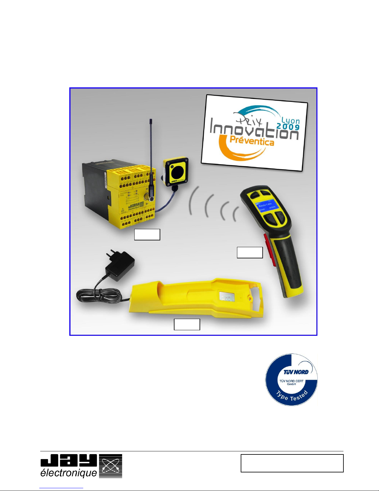
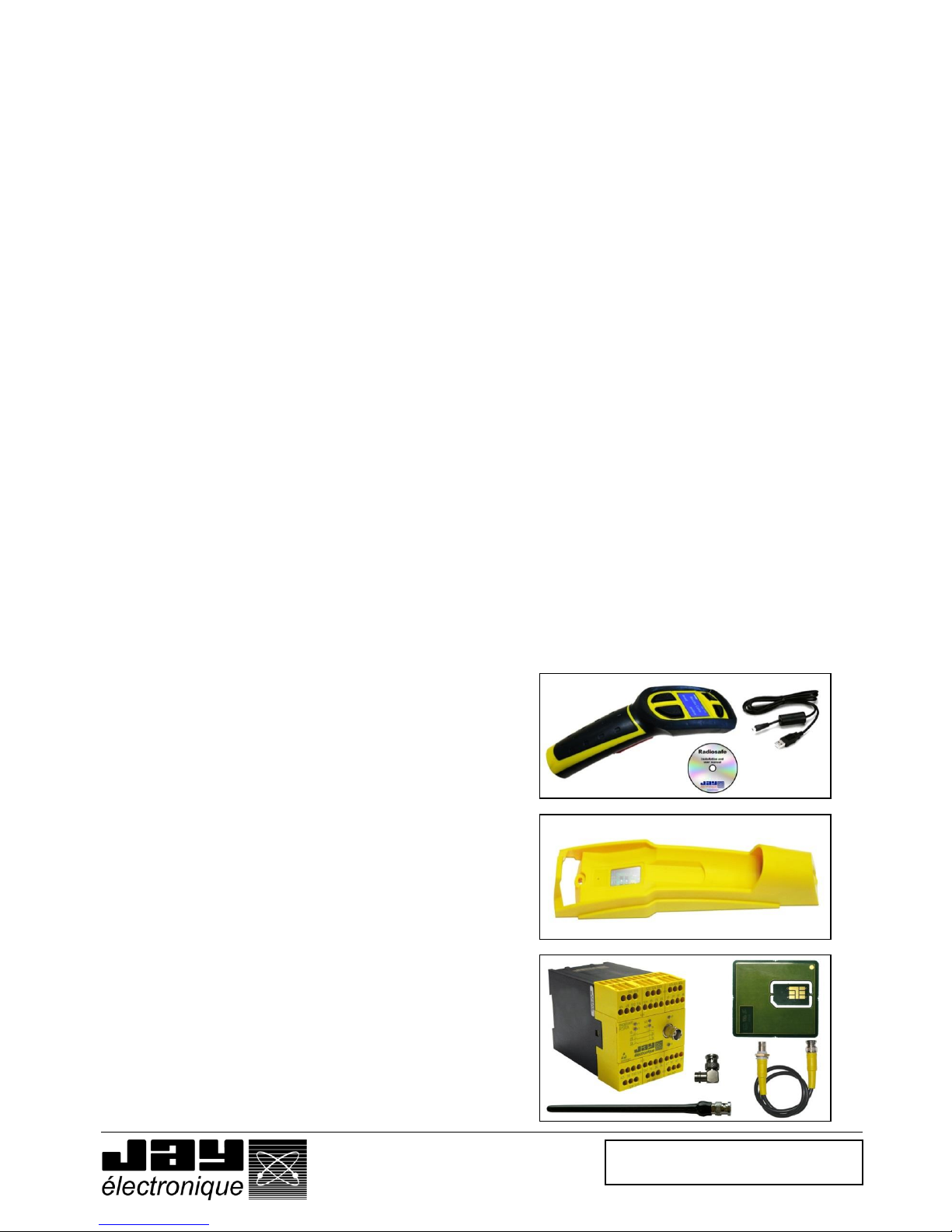
The "RADIOSAFE wireless enabling handle" comprises :
The wireless enabling handle : RSEP4B-* (trigger with 2
positions) or ref RSEP41-* (trigger with 3 positions) supplied
with :
o A battery
o A handle configuration software
o The installation and user manual (CD)
A charger, ref. : RSCP-*
A radio receiver, ref. : RSRB*400-* supplied with :
o A SIM card
o A ¼ wave antenna, ref. : VUB084
o A BNC elbow connector, ref. : VUB060
o A 50 cm antenna extender, ref. : VUB170
Page 6
Doc ref. : 332190D – EN
28.04.2014
Page 6 / 49
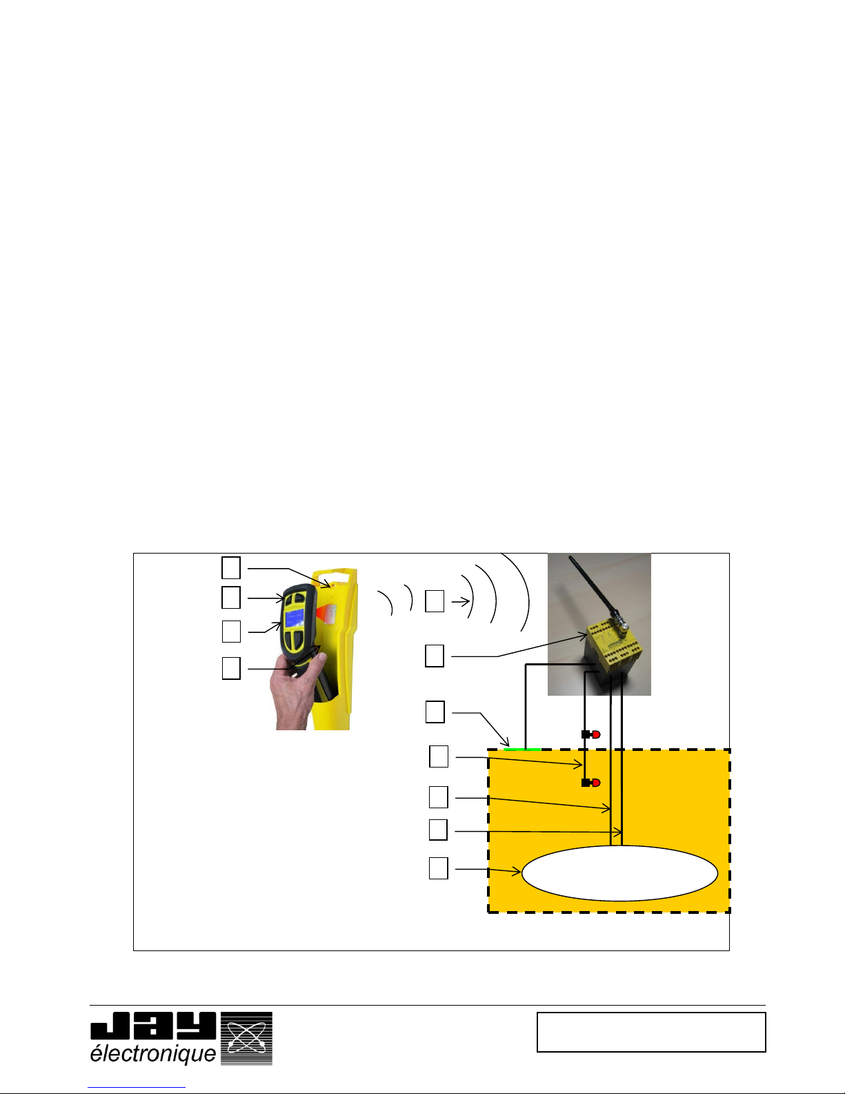
3 Theory of operation
The receiver (R) is integrated in the machine control unit.
The wireless enabling handle (P) transmits, by radiowave, the trigger operating request (G) and possible commands
generated using the buttons (B).
The receiver (R) enables (or not) operation (F) of the machine (M) and transfers the commands (O) assigned to the
buttons.
The receiver (R) stops operation of the machine in the following cases :
Case 1 - Trigger (G) released or clenched (in the case of the 3-position trigger) on wireless enabling handle (P) during
use ;
During use, the wireless enabling handle transmits a stop command as soon as the user releases or
clenches the trigger.
Safety shutdown following stop request or operator incident.
Case 2 - Radio link (L) interrupted during use ;
During use, the wireless enabling handle operates with a continuous radio link with the receiver. If the link is
interrupted more than 300ms, the receiver automatically stops the system.
Safety shutdown prior to loss of control of the stop function.
Case 3 - Procedure for picking up or setting down wireless enabling handle on charger not observed (C) ;
The wireless enabling handle has been removed from its charger and the trigger has not been activated within
the required period of time.
Safety shutdown subsequent to incorrect use of wireless enabling handle.
Case 4 - A secure access area (Z) has been opened without a prior access request;
The access to the area has been opened without prior request by the user, or following a defined time delay for
opening of the secure area access.
Safety shutdown following detection of intrusion into a secure area.
Case 5 - A wired emergency stop system (A), if used, has been opened ;
The wired emergency stop system(s), connected to the receiver, has been opened.
Safety shutdown of machine subsequent to activation of wired emergency stop system(s).
Case 6 - Detection of a fault (see section : « Faults communicated by receiver »)
> See « Procedures » in section 11.
L
P
C
G
Machine
Z
A
M
R
A : Wired emergency stop
system
B : Control button
C : Charger
F : Operation enabled
G : Trigger
L : Radio link
M : Machine controlled
O : Command
P : Wireless enabling handle
R : Receiver
Z : Protected access area
F
O
B
Page 7
Doc ref. : 332190D – EN
28.04.2014
Page 7 / 49
4 Check of functions, initial start-up
This section is aimed at familiarising you with the product.
Detailed procedures are given to allow you to simulate operation of the equipment in its « ex-factory »
configuration.
4.1 « Ex-FACTORY » parameters
Operating mode .................................... : 4 control buttons
Radio channel number ......................... : 64 (434,675MHz)
Transmit power level ............................. : Set to maximum for all handle models
Handle configuration lock ................... : « deactivated »
Time delay (1) ........................................ : “A” selectors set to « 5 » (10 seconds)
Receiver application program ............. : “B” selector set to « 0 » (no area access management)
(1) Time delay for « secure area access inhibit » and « trigger activation » on enabling handle pick-up
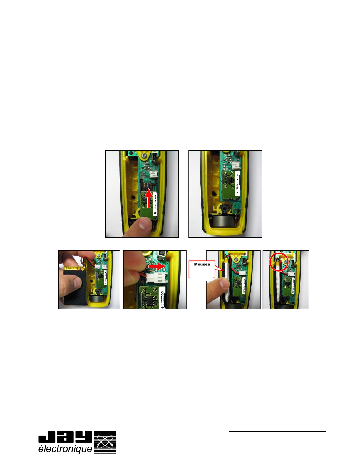
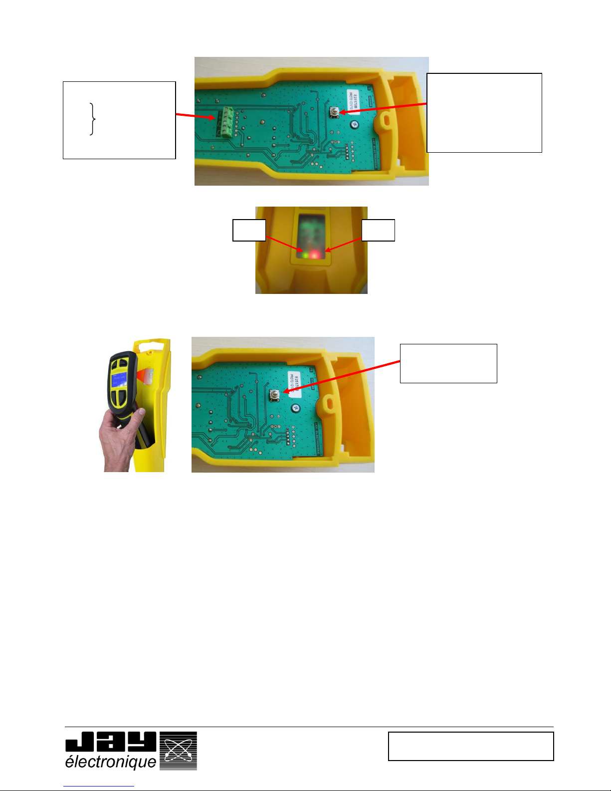
4.2 Setting the wireless enabling handle into service
• Step 1 Open the enabling handle
• Step 2 Insert the SIM card supplied with the receiver or separately (pay attention to insertion direction)
• Step 3 Connect the battery
• Step 4 Close the handle using a Pozidriv No.1 screwdriver (2), by screwing in, without blocking, the central
screw, followed by the two top screws and the bottom screw. Finish up by blocking the 4 screws.
(2) Do not use an electric screwdriver without torque control.
• Notes
The SIM card contains the complete configuration for the handle.
The basic functions of the wireless enabling handle can be configured directly using the buttons on the front panel. The basic functions
are :
- Read information on handle (identity code, SIM card serial number, software version, number of current configuration file)
- Change screen display language
- Change frequency channel
- Change power level
- Lock handle configuration
To modify the basic parameters, refer to section 5.
Protective
foam
Page 8
Doc ref. : 332190D – EN
28.04.2014
Page 8 / 49
4.3 Setting the charger into service
• Step 1 Connect a 24VDC (+/- 5 %) stabilised power supply to the – (ground) and + (+24Vdc) terminals.
• Step 2 Supply the charger
The red indicator light V2 should come on.
• Step 3 Pair the handle with its charger by placing it in front of its charger and pressing the association button
at the rear of the charger.
The green indicator light V1 (handle present) on the charger should come on.
• Step 4 Release the pairing button
The green indicator light V1 should stay on. The handle is now paired with the charger.
• Notes
When the handle is located at a distance greater than 30cm from the charger, the green indicator light
V1 goes off. It comes back on when the handle is brought nearer to the charger.
The 2 outputs, S1 and S2, are active when the handle is present on the charger.
The handle is charged contact-free (inductive charge). The charger is equipped with a « handle
presence » detection function. This detection function inhibits the enabling handle and keeps the
receiver safety relays active.
The "handle on charger" condition is monitored by an infrared link.
24 VDC power supply
S1
S2
Pairing button:
This button ensures
pairing of the handle with
the charger. The charger
will learn the Identity code
of the handle.
V2
V1
Button used to pair
handle with charger.
« Handle on
charger »
outputs
Page 9
Doc ref. : 332190D – EN
28.04.2014
Page 9 / 49
4.4 Warning regarding the battery of the enabling handle
There is a risk of explosion if battery is replaced by a battery of an incorrect type. Only the battery intended
for the enabling handle and supplied by JAY Electronique is suitable
Only the charger ref. :RSCP from JAY Electronique is suitable for recharging the battery of the enabling
handle.
Do not expose the battery to temperature above 50°C (122°F).
Do not open or attempt to modify the battery.
Failure to follow instructions may cause fi re or explosion.
Please respect the dispose of used batteries as directed.
The load must be performed in a dry (protection against moisture IP 20), sheltered and protected place.
Page 10
Doc ref. : 332190D – EN
28.04.2014
Page 10 / 49
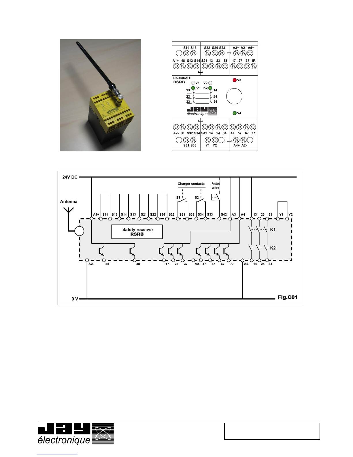
4.5 Setting up the product
Test wiring: does not take account of your application :
• Step 1 Prepare a 24VDC (+/- 5 %) stabilised power supply, 500 mA min.
Prepare a pushbutton, for the reset function.
• Step 2 Wire the receiver as follows :
- Shunt the terminal pairs [S11-S12], [S13-S14], [S21-S22], [S24-S23] and [Y1-Y2]
- Connect the terminals S31, S32, S33 and S34 to the charger
- Install a reset button between terminal S42 and the +24Vdc of the power supply
- Connect the +24VDC of the stabilised power supply to terminals A1+, A3 and A4
- Connect the power supply ground to the two A2- terminals
• Step 3 Supply the receiver
Indicator light V1 of the receiver comes on steady and indicator light V2 of the receiver flashes
regularly.
Page 11
Doc ref. : 332190D – EN
28.04.2014
Page 11 / 49
4.6 Testing the unit
• Step 1 Place the handle on the charger.
The green indicator light on the charger comes on. If not, check that the handle is paired with the
charger. Refer to the section « Setting the charger into service ».
• Step 2 Press the reset button to engage the output relays of the receiver, K1-K2
The 2 indicator lights K1 and K2 should come on and indicator light V2 of the receiver should go
off.
• Step 3 Pick up the enabling handle and place the trigger in the « active » position within 10 seconds.
The antenna symbol should appear on the display screen.
Notes : 1 - Safety relays K1 and K2 deenergise when the trigger is released or clenched (in the case of 3-
position trigger).
2 - Safety relays K1 and K2 energise again when the trigger is reactivated after it has gone through
the « released » position (1)
3 – The safety relays remain active when the trigger is released within 30 cm of the charger.
(1) Wait 3 or 4 seconds before you reactivate the trigger to allow the receiver to correctly reinitialise.
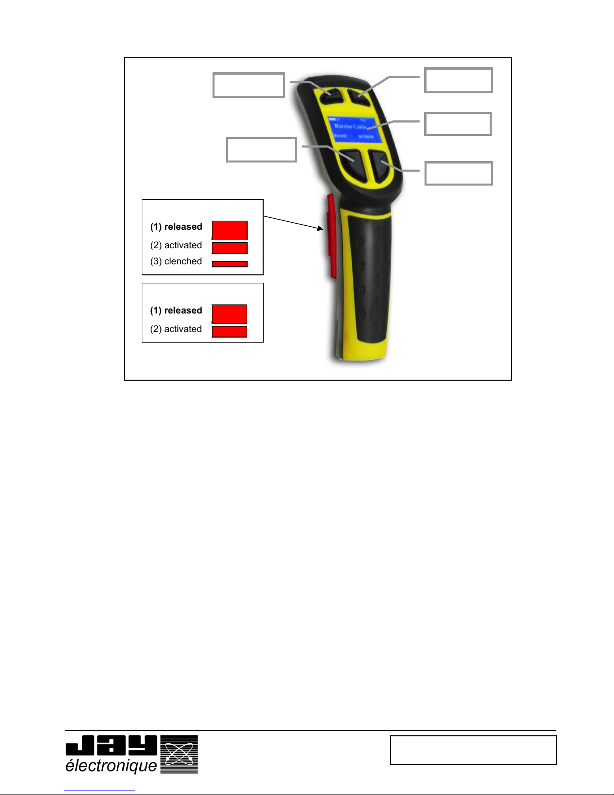
Button B4
Button B2
Button B3
Button B1
Display
(1) released
(2) activated
(3) clenched
3-position trigger
(1) released
(2) activated
2-position trigger
Page 12
Doc ref. : 332190D – EN
28.04.2014
Page 12 / 49
5 Setting the product into service
Experience has shown that functional reliability basically depends on :
- the quality of the electrical power supply and the associated protection circuits ;
- the characteristics of the components connected to the receiver.
- the position of the reception antenna.
- the configuration and wiring of the various components
5.1 Electrical power supply, installation and wiring
Final wiring in the receiver cabinet and of the charger must only be performed with the power shut down.
5.1.1 Receiver
Recommendations :
- The product should be installed near the intervention area.
- The receiver should be installed in a housing.
- A wire-type emergency stop should be wired on the front panel of the housing ; this emergency stop can be
used when the handle is set on its charger.
- Provide a position for a reset button, required to reset the receiver module when setting into service, following
a fault, or following a safety shutdown.
- On the top of the housing, secure a 3-color (green, orange, red) indicator light column to indicate the operating
status of the wireless enabling handle.
- Near the indicator light column, fasten an information sign indicating the meaning of the various states of the
indicator lights (example given on last page of this manual).
- The receiver must be supplied with 24 VDC +/- 15% across terminals [A1+ and A2-].
- Provide a protection system implementing a 1 amp delayed fuse in series on input A1 (24V DC) of the
receiver.
- Familiarise yourself with the other characteristics in the section entitled « Technical characteristics »
5.1.2 Charger
- The charger must be supplied with 24VDC +/- 5%. (Jay charger, ref. : RSCU)
- Electrical protection : 0.5 A delayed fuse.
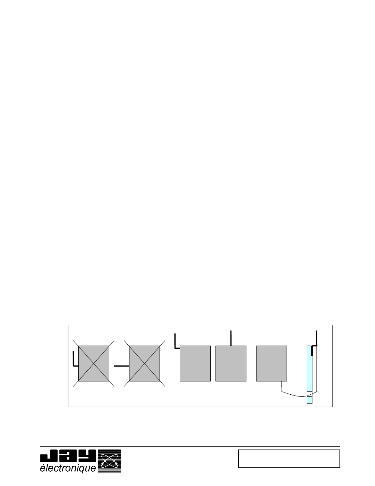
5.2 Receiver antenna
The receiver is supplied with an antenna, a 50 cm antenna extension and a BNC-BNC elbow connector.
If a metal housing is used, the receiver antenna should be mounted on the top of the housing.
If a plastic housing is used, the antenna can be connected directly on the receiver using the BNC elbow
connector supplied with the receiver.
If poor radiowave propagation is observed, for example, intervention in a closed enclosure, the receiver
antenna should be mounted inside the enclosure.
NOK
NOK
OK
OK
OK
Page 13

Doc ref. : 332190D – EN
28.04.2014
Page 13 / 49
5.3 Intervention mode and operation of enabling handle
The intervention mode and operation of the product depend on the needs of the application.
Intervention mode
- The wireless enabling handle can be used on machines in the following modes :
o « Monitoring - Diagnostic»
o « Manual control ».
The detailed intervention conditions are given in the next section.
The wireless enabling handle can be configured to manage access to a machine area. For this purpose, the
« 4 control buttons » mode is used.
The principle of the machine area access function is detailed below :
- Application programs 8 and 9 of the receiver are dedicated to this purpose (chosen using the 2 “B”
selectors)
- The access gate or safety light barrier is controlled by the receiver using 2 inputs.
- The user makes a request for authorisation to access the machine area using one of the two buttons (B1
or B2) on the wireless enabling handle.
- This request initiates a time delay (1) inhibiting the two gate contacts or the safety output of a safety light
barrier.
- While the gate is opened or while crossing the safety light barrier, the receiver safety relays remain
active.
- Once the gate has been closed or the safety light barrier has been crossed, the inhibit condition is
stopped to prevent entry of any other person.
(1) configurable by 2 « A » selectors on receiver.
Handle operating mode
- The wireless enabling handle can be used in the following 2 operating modes :
o « 4 control buttons »
o « function selection ».
This will depend on the number of commands to be generated. For an application requiring more than 4
commands to be generated, the handle will need to be configured in « function selection » mode using the
« Dialog RSP » PC software supplied with the handle.
5.3.1 Conditions for intervention in «monitoring - diagnostic» mode
Safety condition in this intervention mode :
This intervention mode must satisfy the requirements of standard NF EN12100-2 §5.5 «Additional preventive
measures».
In this intervention mode, the product provides a wireless individual protection system for qualified personnel
intervening for equipment monitoring or diagnostic purposes, whether in downgraded operation or not.
The regulations prohibit direct intervention on the equipment.
The « monitoring - diagnostic» intervention mode is only possible provided the enabling handle is configured for
« 4 control buttons » operation (ex-factory configuration)
The « monitoring - diagnostic» intervention mode is only acceptable provided:
o The risk assessment shows that injury to the intervening technician can be avoided in the event
of an immediate danger.
o The risk assessment shows that the time required to stop the equipment by releasing or
clenching the trigger is sufficiently short to prevent placing the intervening technician in danger.
o An emergency shutdown of the equipment by clenching or release of the enabling handle trigger
does not produce any additional dangerous condition.
o The operator can keep the enabling handle in his hand without releasing the trigger throughout
the time of the intervention.
In the « monitoring - diagnostic » mode, the receiver can manage (or not) access to the machine area.
Page 14
Doc ref. : 332190D – EN
28.04.2014
Page 14 / 49
5.3.2 Conditions for intervention in « manual control » mode
Safety condition in this intervention mode
This mode satisfies the requirements of standard NF EN12100-2 §4.11.8 « Guidelines relative to manual control ».
This mode is possible insofar as control of the movement using the control buttons associated to action on the handle
trigger is sufficient to stop the equipment if necessary.
The « manual » intervention mode is only acceptable provided:
- The risk assessment shows that injury to the intervening technician can be avoided in the event of an
immediate danger.
- The risk assessment shows that the time required to stop the equipment by releasing or clenching the trigger
is sufficiently short to prevent placing the intervening technician in danger.
- An emergency shutdown of the equipment by clenching or release of the enabling handle trigger does not
produce any additional dangerous condition.
Conditions for use of product in « manual control » intervention mode
- The equipment must be stopped from the supervision station or by opening an access gate.
- The enabling handle must be removed from its charger. The « handle withdrawn » information is accessible
on output 17 of the receiver (active at the high state).
- To ensure the « manual controls » on the equipment, the operator must actuate the trigger to the active
position, and use the four control buttons to generate a command.
- So long as the handle is not set down on it charger (operator has not withdrawn from intervention area), the
equipment will not be able to operate again in automatic mode.
- The « manual control » intervention mode is possible in « 4 control buttons » mode and in « function
selection » mode.
- The « manual control » intervention mode does not allow the receiver to manage access to a machine area.
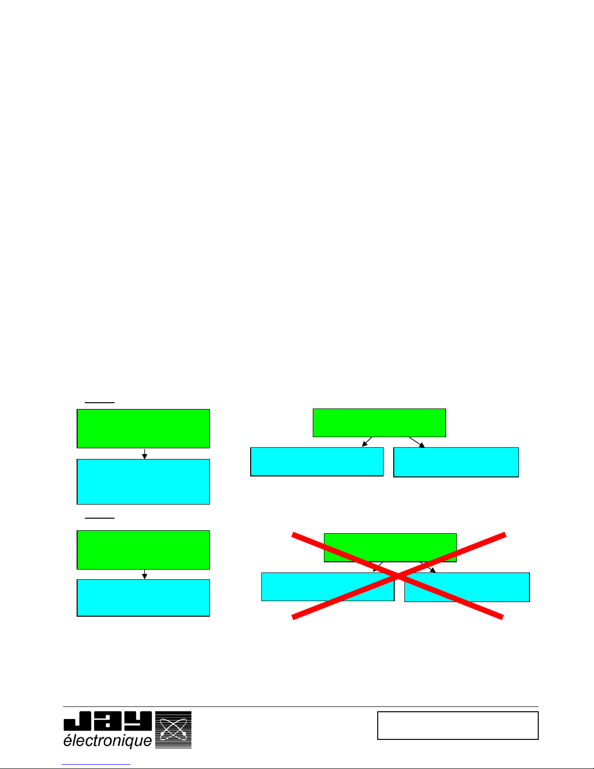
5.3.3 Summary of conditions for intervention on machine.
The conditions for intervention on a machine using the enabling handle can be summarised as follows :
Case 1 : Application without management of machine area access by receiver
Case 2 : Application with management of machine area access by receiver
(1) With a machine in operation, the regulations prohibit acting on the machine in the « monitoring - diagnostic » mode.
« manual control »
intervention mode
« 4 control buttons »
operating mode
« Function selection »
operating mode
« Diagnostic- monitoring »
intervention mode
(1)
« 4 control buttons »
operating mode
(control buttons not used – only
trigger is used)
« Diagnostic- monitoring »
intervention mode
(1)
« 4 control buttons »
operating mode
(Button(s) used .)
« manual control »
intervention mode
« 4 control buttons »
operating mode
« Function selection »
operating mode
Page 15
Doc ref. : 332190D – EN
28.04.2014
Page 15 / 49
5.3.4 Configuration of enabling handle operating mode
The wireless enabling handle operating mode can be configured using the Dialog RSP PC software supplied with the
handle.
This software is used to :
- Configure the handle in « 4 control buttons » or « function selection » operating mode.
- Modify the content of the screen display on the handle by loading or creating new pictograms.
- Save or re-load a new handle configuration in the SIM card of the handle.
- Re-load an old configuration.
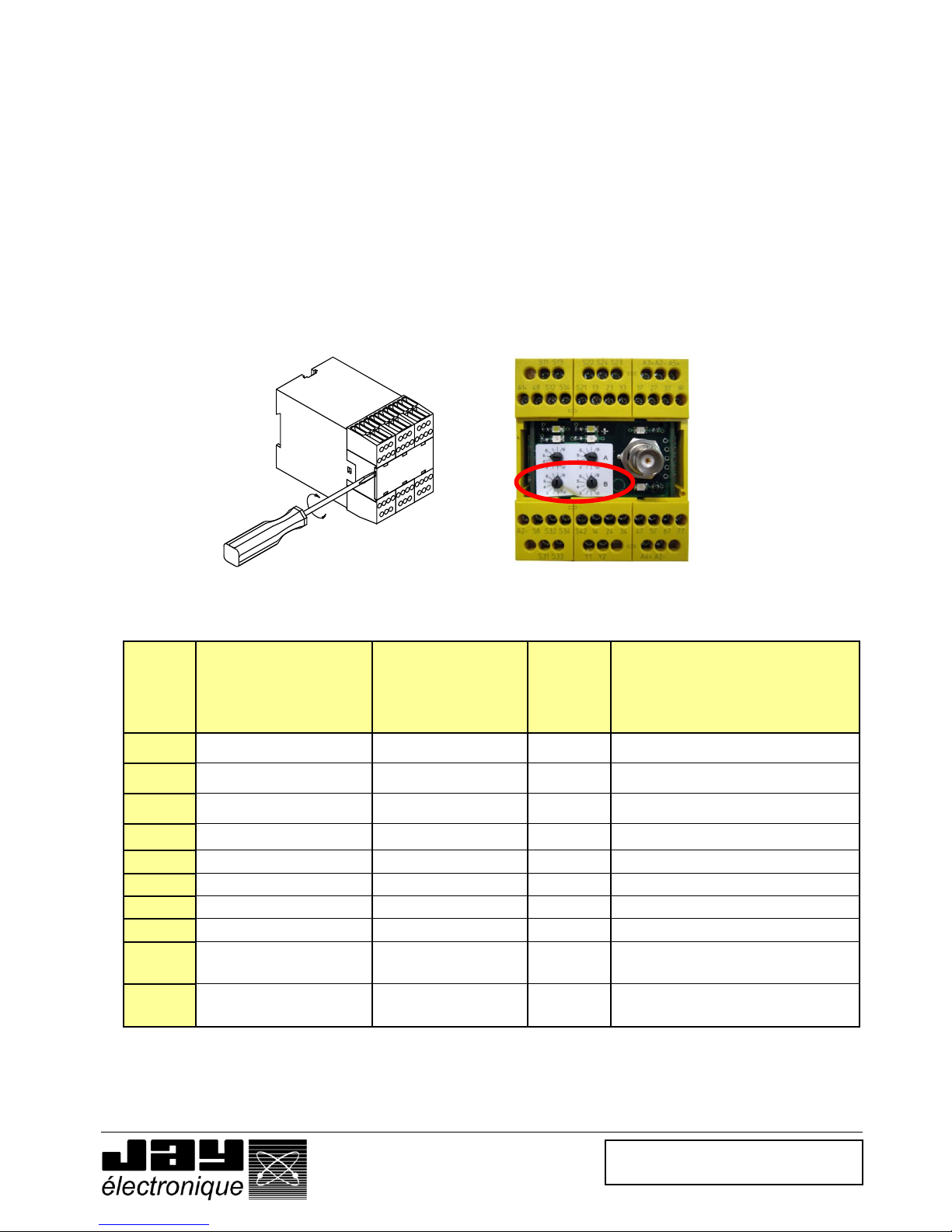
5.3.5 Receiver : selecting the program
The receiver has 10 programs which can be selected using the two « B » selectors.
Access to the configuration selectors is obtained by removing the front panel of the receiver.
Important : the 2 « B » selectors must be set to the same position to validate the selected program.
Position of
« B »
selectors
Reset mode, following a wired
emergency shutdown or
opening of a gate
Reset mode, following
release or clenching of the
handle trigger
Dangerous
area access
control
Remarks
0
Control console
Trigger
NO
1
Control console
Control console
NO
2
Automatic
Trigger
NO
3
Automatic
Control console
NO
4
Not used
5
Not used
6
Not used
7
Not used
8
Control console
Trigger
YES
The receiver module controls access to the
dangerous area using the handle.
9
Control console
Control console
YES
The receiver module controls access to the
dangerous area using the handle.
Note : The « manual control » intervention mode cannot be used for programs 8 and 9.
Page 16

Doc ref. : 332190D – EN
28.04.2014
Page 16 / 49
5.3.6 Adjusting the machine area access time.
The machine area access time and the time during which the gate or safety light barrier is inhibited to allow
intervention in a machine area are configurable using the 2 « A » selectors on the receiver.
Important : The 2 « A » selectors must be set to the same position to validate the selected time delay.
Position of «A»
selectors
0 1 2 3 4 5 6 7 8
9
Machine area
access time
5 s.
6 s.
7 s.
8 s.
9 s.
10 s.
15 s.
20 s.
25 s.
30 s.
Inhibit time (1)
(Muting)
5 s.
10 s.
20 s.
40 s.
1 min.
2 min.
3 min.
4 min.
5 min.
10 min.
Caution : The machine area access time is the same as the enabling handle pickup time after it has been withdrawn
from its charger.
(1) This time corresponds to the muting time of a gate or safety light barrier. Once the gate has been closed or the
barrier has been crossed, the muting function is stopped to prevent any unauthorised person from entering into the
area.
Page 17

Doc ref. : 332190D – EN
28.04.2014
Page 17 / 49
5.4 Receiver : operation and wiring
5.4.1 Operation and wiring of function outputs
The receiver is equipped with 6 solid state outputs (100 mA max). Assignment of the enabling handle buttons (B1 to
B4) with respect to the outputs depends on the operating mode selected using the RSP configuration software.
Assignment of receiver outputs in « 4 control buttons » mode.
In the « 4 control buttons » mode, buttons B1,
B2, B3 and B4 of the enabling handle respectively
control outputs 27, 37, 47 and 57.
Output 67 is activated as soon as one of the four
buttons is pressed (common output)
Reminder : If the receiver is managing machine area access, B1 and/or B2 and the associated outputs 27 and/or 37
are used to process the muting enable request for the gate or safety light barrier.
Assignment of receiver outputs in « function selection » mode.
This operating mode is configurable using the dialog RSP PC software.
In « function selection »mode, buttons B3 and
B4 are used to select the machine component to
be controlled (F1 to F4) and buttons B1 and B2
are used to select the direction of movement.
Reminder : Machine area access cannot be managed in the « function selection » operating mode.
Caution, the loads connected to the outputs must not deliver more than 100 mA with 24VDC.
Receiver RSRB outputs
27
37
47
57
67
77
Selection of
function by B3
and B4
F1
B1
X X
B2
X X
F2
B1
X X
B2
X X
F3
B1
X
X
B2
X
X
F4
B1
X
X
B2
X
X
Receiver RSRB outputs
27
37
47
57
67
77
B1
X X
B2
X X
B3
X X
B4
X X
Page 18

Doc ref. : 332190D – EN
28.04.2014
Page 18 / 49
5.4.2 Operation and wiring of safety relays K1-K2.
The safety stop chain is cut out by safety relays K1 and K2 (internal to receiver) which control the contacts
accessible by terminals 22-23 and 32-33.
The state of relays K1 and K2 depends : on the position of the trigger (table 1), possible faults detected, and
possible radio link losses.
Other external safety stop devices can be added including an emergency stop palmswitch and a gate control
device, wired to the inputs provided for this purpose on the receiver. The state of the inputs will act directly on
relays K1 and K2 through the receiver.
The state of safety relays K1 and K2 is available between terminals 13 and 14.
State of safety outputs as a function of enabling handle trigger position :
Trigger
position
State of
safety relays
K1 and K2
S14
State of contact chains accessible by terminals
S13-S14 / S23-S24 / S33-S34
Released
Inactive
0
Open
Active
Active
+24 Vdc
Closed
Clenched
Inactive
+24 Vdc
Open
Page 19

Doc ref. : 332190D – EN
28.04.2014
Page 19 / 49
5.4.3 Monitoring of main contactor : operation and wiring
Input « Y1-Y2 » is used to monitor the state of the contactor(s) connected to the K1-K2 safety outputs.
The state of the contactor contact(s) wired to input Y1-Y2 must be closed in order to reset the receiver.
Note : If this input is not used, wire a jumper across inputs Y1 and Y2.
5.4.4 Reset button : wiring and management
Following a safety shutdown, safety relays K1 and K2 deernergise and open the contacts accessible by terminals 22-23
and 32-33.
In accordance with the application program selected using the two « B » selectors on the receiver, the safety relays are
automatically reset, or reset is requested using a pushbutton wired on input S42.
This being said, the reset button is always necessary except with application program « 2 ».
Note : For information on the reset modes selected using the 2 « B » selectors, refer to the section entitled “ Receiver,
selecting a program “.
Page 20

Doc ref. : 332190D – EN
28.04.2014
Page 20 / 49
5.4.5 Wiring of a wired safety shutdown device.
The external safety shutdown devices (wired safety shutdown palmswitches ...) must be wired to the « Emergency
stop » inputs. To do so, you must use external safety shutdown devices comprising two redundant contacts. One of
the contacts must be connected across terminals S11-S12, and the other across S13-S14 (fig 2).
Note : If this wired emergency stop function is not used, you must wire two jumpers across S11-S12 and S13S14.
5.4.6 Wiring of a machine area access authorisation request function.
- The enabling handle must be configured in the « 4 control buttons » operating mode.
- Output 27 (associated to button B1) or output 37 (associated to button B2) must be connected to input S34 to
ensure the machine area access authorisation request.
- Using the Dialog RSP PC software, you can load a pictogram suited to this application on the enabling handle
screen. See pictograms available in Dialog RSP PC software library.
Note : The wiring diagram shown below is designed for an area access request using button B1 (output 27)
Note : The wiring is the same for an access by gate or an access protected by a safety light barrier .
Page 21

Doc ref. : 332190D – EN
28.04.2014
Page 21 / 49
5.4.7 Wiring of an equipment with area access protection
The enabling handle can be used with machinery located in an area with protected accesses, or with machinery for which
access is not protected.
On equipment with protected access, the wireless enabling handle can be used to generate access requests and can control
the access to a protected area :
- The accesses must be equipped with a system used to detect passage of a person.
- For an access by which a gate is opened and closed, 2 contacts must be wired across terminals S21-S22 and S23-S24 of
the receiver.
- For an access by which a safety light barrier must be crossed, the barrier outputs must be wired to inputs S22- and S24
of the receiver.
- The receiver monitors the coherency and the state of the 2 contacts of the gate or of the two outputs of the safety light
barrier.
- On user request (handle button B1 or B2 pressed and released), the receiver temporarily inhibits (adjustable time delay) the
two contacts of the gate or the two outputs of the safety light barrier.
- The orange indicator light on the indicator light column wired on output 58 flashes.
- The user can enter or exit the secured area without tripping the two safety outputs K1 and K2 of the equipment.
- Once the gate is closed or the safety light barrier is crossed, the orange indicator light on the indicator light column stops
flashing and is steadily lit
Diagram 1 : Access protected by access gate.
Diagram 2 : Access protected by safety light barrier.
Page 22

Doc ref. : 332190D – EN
28.04.2014
Page 22 / 49
5.4.8 Wiring of an equipment without area access protection
If the equipment does not have a peripheral protection system with a machine area access feature, you must connect
jumpers across the machine area access monitoring inputs, S21-S22 and S23-S24.
5.4.9 Wiring of “handle on charger” detection function
This function must be wired to inhibit the enabling handle when it is not used. Once an intervention on a machine is
completed, the operator must place the enabling handle on its charger in order to allow the equipment to operate
again in automatic mode.
The two outputs, S1 and S2, must be connected to the receiver.
- These should be connected to inputs S31-S32 and S33-S34 when the receiver is not used to manage
machine area access (see diagram 1)
- These must be connected in series to inputs S31-S32 when the receiver is used to manage machine area
access. The passage request must be connected on input S33 (see diagram 2)
- Output 17 gives the “handle on charger” status (output active = handle present).
Diagram 1 : Wiring for configuration without machine area access
Page 23

Doc ref. : 332190D – EN
28.04.2014
Page 23 / 49
Diagram 2 : Wiring for configuration with machine area access (example with gate)
5.4.10 Wiring of indicator light column on receiver
We strongly recommend that you wire an indicator light column on the receiver. The column will indicate the status of the
equipment and of the wireless enabling handle. The indicator light column status information panel should be fastened near to the
indicator light column (an example is given in the last page of this manual).
The consumption of the indicator lights of the column must not exceed 100 mA with 24VDC. If this is not the case, the indicator
lights should be relayed.
Status of lights on indicator light column
Indicator
light
On steady
Flashing
Off
Remarks
Green
Equipment in service
Equipment stopped
Red
Equipment stopped
Receiver on standby for
reset
Equipment in service
Red and orange indicator lights
will flash a specific number of
times in the event of a receiver
malfunction
Orange
Handle removed from
charger
Handle removed from
charger or area access
request
Handle on charger
Page 24

Doc ref. : 332190D – EN
28.04.2014
Page 24 / 49
5.4.11 Wiring of receiver power supplies
This operation should be performed at the end of the wiring procedure.
Page 25

Doc ref. : 332190D – EN
28.04.2014
Page 25 / 49
5.5 Charger : wiring and management.
5.5.1 Association of charger and wireless enabling handle
If the charger has not been associated to its handle, refer to the section entitled « Setting the charger into service ».
5.5.2 Wiring of charger power supply
To supply the charger, refer to the section entitled « Setting the charger into service »
5.5.3 Taking the wireless enabling handle off its charger
When the wireless enabling handle is withdrawn from its charger, you have a limited time delay to activate the trigger.
After this time delay, safety relays K1 and K2 de-energise to stop the equipment.
This time delay is configurable between 5 and 30 seconds by 2 «A» selectors on the receiver.
The 2 selectors must always be set to the same position.
Position «A»
selectors
0 1 2 3 4 5 6 7 8
9
Handle pickup time
delay
5 s.
6 s.
7 s.
8 s.
9 s.
10 s.
15 s.
20 s.
25 s.
30 s.
Note : The two « A » selectors are also used to define the machine area access time described in the previous section. If this area
access function is also used, the position of the two « A » selectors must be chosen to best satisfy the two functions
5.5.4 Setting the wireless enabling handle on its charger
When you go to set the wireless enabling handle on its charger, you must keep the trigger activated until the green
indicator light on the charger comes on (when you are within 30 cm of the charger). You can then release the trigger
without de-energising the safety relays, then set the wireless enabling handle on its charger.
The enabling handle recharges once it is engaged on its charger.
Page 26

Doc ref. : 332190D – EN
28.04.2014
Page 26 / 49
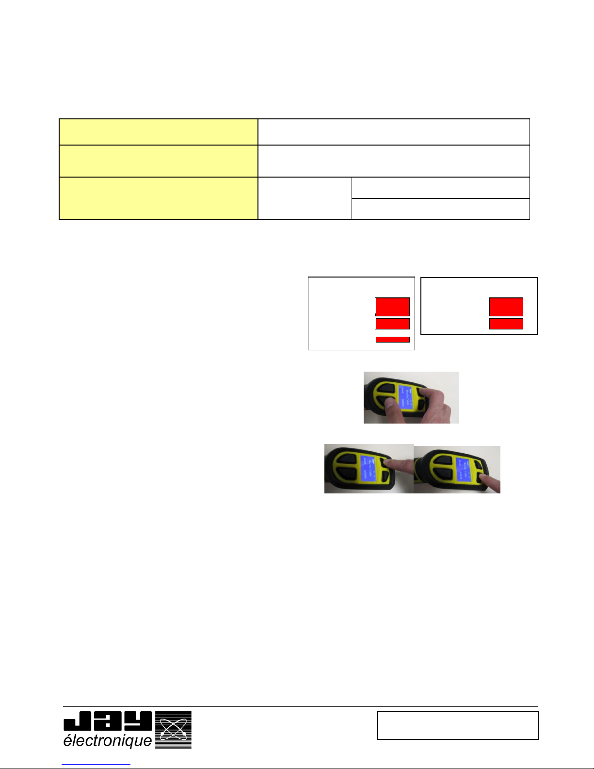
5.6 Language selection
Several dialog languages are available with the enabling handle display.
The language is chosen by simultaneously pressing buttons B3 and B4.
• Pick up the handle, leaving the trigger in the
released position (1).
• *Simultaneously press buttons B3 and B4
The language currently used is displayed.
• Press the – (B3) or + (B4) button to change
language.
Note : If the handle is locked against installation
configuration changes, see §3.3.
• Validate the new working language by pressing
OK* (B1).
• or, cancel the change by pressing EXIT (B2).
Page 27

Doc ref. : 332190D – EN
28.04.2014
Page 27 / 49
5.7 Radio working frequency
5.7.1 Selection of radio working frequency.
To limit unintentional cut-outs linked to radio interference, it is important to choose a radio channel (frequency) which is available.
Use the following guidelines in making your choice :
- Consider the point of installation of the receiver as the centre of the radio link ;
- Estimate the maximum distance « D » which may occur between the operator and the receiver ;
- Identify the frequencies used by all the radio transmitters located within a radius of 2xD.
- Choose a frequency which is as far as possible from those used by the nearest transmitters, and which is not being used by
the transmitters identified.
5.7.2 List of channels and radio frequencies (in accordance with enabling handle model)
433-434 MHz bands, intervals between adjacent channels: 0.025 MHz
Channel
No.
Frequency
MHz
Channel
No.
Frequency
MHz
Channel
No.
Frequency
MHz
01
433,100
23
433,650
45
434,200
02
433,125
24
433,675
46
434,225
03
433,150
25
433,700
47
434,250
04
433,175
26
433,725
48
434,275
05
433,200
27
433,750
49
434,300
06
433,225
28
433,775
50
434,325
07
433,250
29
433,800
51
434,350
08
433,275
30
433,825
52
434,375
09
433,300
31
433,850
53
434,400
10
433,325
32
433,875
54
434,425
11
433,350
33
433,900
55
434,450
12
433,375
34
433,925
56
434,475
13
433,400
35
433,950
57
434,500
14
433,425
36
433,975
58
434,525
15
433,450
37
434,000
59
434,550
16
433,475
38
434,025
60
434,575
17
433,500
39
434,050
61
434,600
18
433,525
40
434,075
62
434,625
19
433,550
41
434,100
63
434,650
20
433,575
42
434,125
64
434,675
21
433,600
43
434,150
22
433,625
44
434,175
Note : In the extended range version RSEP41, only channels 40 to 64 are accessible.
Page 28

Doc ref. : 332190D – EN
28.04.2014
Page 28 / 49
5.7.3 Reading the working frequency.
• Pick up the handle, leaving the trigger in the released
position.
• Simultaneously press buttons B1 and B2
The radio channel programmed is displayed
• Press EXIT (B2) to exit.
Note : The receiver working frequency is not accessible.
5.7.4 Changing the working frequency
• Switch on the receiver RSRB
• Pick up the handle, leaving the trigger in the
released position (1).
• Simultaneously press buttons B1 and B2
The programmed radio channel is displayed
• Press the – (B3) or + (B4) button to go to the
desired radio channel.
Note : If the handle is locked against installation
configuration changes, see §3.3.
• Validate the new working frequency by pressing
OK* (B1).
- Either for 1 second = fast mode
(to be used only if the receiver and enabling
handle were set on the same frequency)
- Or, for 3 seconds = long scan mode.
(to be used if receiver and handle can be set
on different frequencies)
The word SCAN is displayed on the
screen
• Release the OK button (B1)
• Hold the trigger in the activated position until you
get the indication to release it.
(In long scan mode, the channel Nos., C01 to
C64 scroll on the display for around 30
seconds).
*Note : Only the channels authorised in accordance with the handle model can be used.
(1) released
(2) activated
(3) clenched
3-position trigger
(1) released
(2) activated
(3) clenched
3-position trigger
(1) released
(2) activated
2-position trigger
(1) released
(2) activated
2-position trigger
Page 29
Doc ref. : 332190D – EN
28.04.2014
Page 29 / 49
5.8 Radio transmit power
5.8.1 Transmit power selection
We recommend that you increase the power when the desired radio ranges are great or when radio interferences
produce accidental cut-outs.
It is preferable to decrease the power when working at limited ranges and where several systems are working together
within a radius of less than 10m.
Power
Min. --------------------------------- Max.
Radio power level scale
1 -------------------------------------- 10
Average range (1)
30 m -------------
150 m (handle with standard range)
250 m (handle with extended range)
(1) = The average range will depend on the product environment (presence of metal obstacles, …)
5.8.2 Reading/changing the transmit power
• Pick up the handle, leaving the trigger in the
released position.
• Simultaneously press buttons B2 and B3
The transmit power used is displayed
• Press the – (B3) or + (B4) button to change the
transmit power.
Note : If the handle is locked against installation
configuration changes, see §3.3.
• Validate the selection by pressing OK (B1).
• Press EXIT (B2) to exit
(1) released
(2) activated
(3) clenched
3-position trigger
(1) released
(2) activated
2-position trigger
Page 30

Doc ref. : 332190D – EN
28.04.2014
Page 30 / 49
5.9 Identity code
5.9.1 Identity code selection
The identity code is used to pair the handle and its receiver.
To communicate with a receiver RSRB, the handle must be programmed with the same identity code.
5.9.2 Reading the identity code, software version and SIM card serial number
• Pick up the handle, leaving the trigger in the
released position.
• Simultaneously press buttons B2 and B4
The identity code used, the software version
and the SIM card serial number are displayed on
the screen.
• Press EXIT (B2) to exit.
The receiver identity code is given on the external label.
5.9.3 Changing the identity code
The identity code programmed in the handle is stored in the SIM card.
You can change the identity code using the Dialog RSP software (see Dialog RSP manual) or by replacing the SIM
card by a card corresponding to the receiver (see § « Setting backup handle into service », or contact your installer).
Note : The identity code programmed in the receiver cannot be changed.
(1) released
(2) activated
(3) clenched
3-position trigger
(1) released
(2) activated
2-position trigger
Page 31

Doc ref. : 332190D – EN
28.04.2014
Page 31 / 49
5.10 Handle locking function
5.10.1 Locking the handle
You can protect your installation parameters (frequency, transmit power) against handling mistakes by locking the
handle.
We recommend that you activate this protection function on completion of your installation procedure.
Locking the handle will protect you against accidental changes, but will not prevent you from reading the identity code
and the frequency channel, or from running a scan to realign a receiver on the same frequency channel used in the
enabling handle.
5.10.2 Activating/deactivating the locking function
• Pick up the handle, leaving the trigger in the
released position.
• Simultaneously press buttons B1 and B4
The locked status is displayed
• Press the NO button (B3) or the YES button
(B4) to respectively deactivate or activate the
locking function.
• Validate the selection by pressing OK (B1).
• Press EXIT (B2) to exit.
(1) released
(2) activated
(3) clenched
3-position trigger
(1) released
(2) activated
2-position trigger
Page 32
Doc ref. : 332190D – EN
28.04.2014
Page 32 / 49
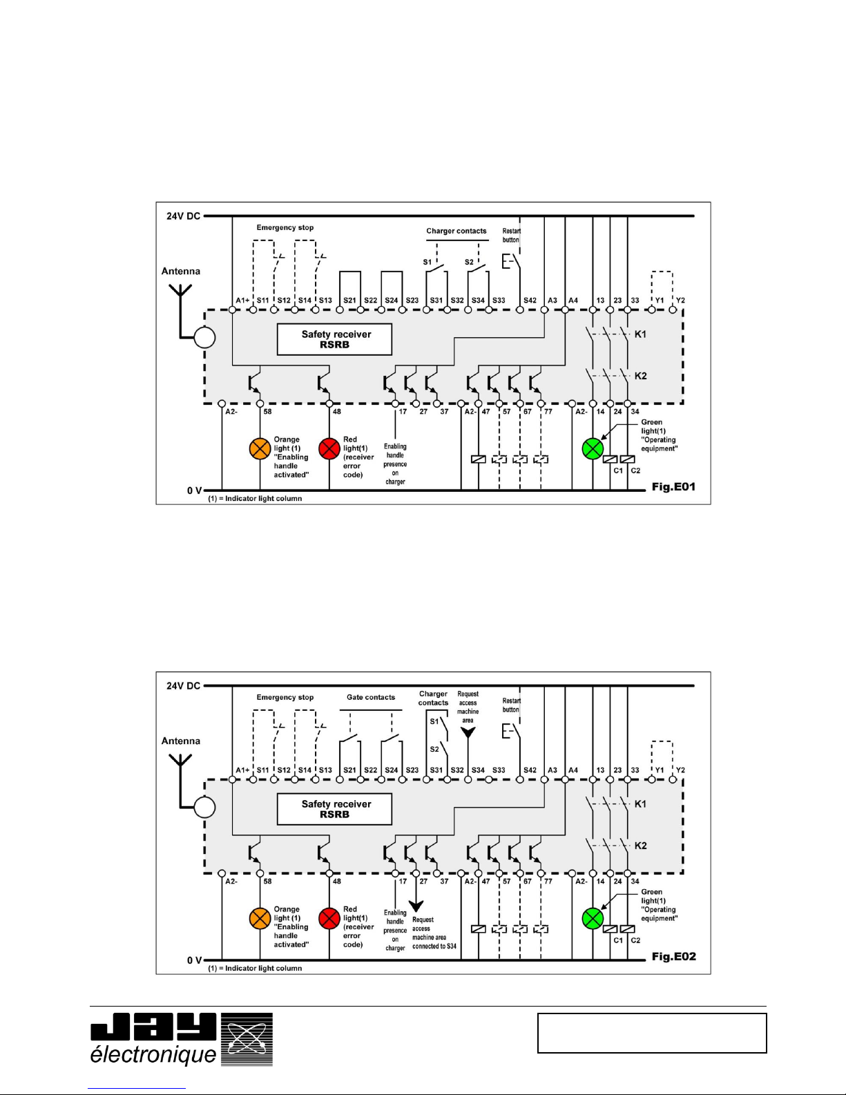
5.11 Receiver wiring examples
5.11.1 Wiring diagram for configuration without access control
The receiver does not manage machine area access.
In addition to the radio input associated to the enabling handle, an emergency stop can be wired to the receiver. Otherwise,
you must wire 2 jumpers across S11-S12 and S13-S14.
To select the correct application program, refer to the « receiver configuration » section.
5.11.2 Wiring diagram for configuration with access control by gate
Reminder : The handle can only be configured in « 4 control buttons » mode.
To monitor access to the machine area, it is necessary to wire two NO contacts on the gate on inputs S21-S22 and S23-S24.
These contacts will be inhibited to allow the operator to access the machine area without deactivating the machine
emergency stop system.
In the diagram below, output 27, associated to button B1 of the handle, is wired to output S34.
For a machine access request using your right hand (pressing B2 instead of B1), be sure to connect output 37 (instead of
27) to input S34.
Page 33

Doc ref. : 332190D – EN
28.04.2014
Page 33 / 49
5.11.3 Wiring diagram for configuration with access control by safety light barrier
Reminder : The handle can only be configured in « 4 control buttons » mode.
To monitor access to the machine area, it is necessary to wire the outputs of the safety light barrier on inputs S21-S22
and S23-S24.
These outputs will be inhibited to allow the operator to access the machine area without deactivating the machine
emergency stop system.
In the diagram below, output 27, associated to button B1 of the handle, is wired to output S34.
For a machine access request using your right hand (pressing B2 instead of B1), be sure to connect output 37 (instead
of 27) to input S34.
Page 34

Doc ref. : 332190D – EN
28.04.2014
Page 34 / 49
6 Diagnostic
In the event of a problem, the handle and the receiver will indicate a fault detected by an error message.
On the wireless enabling handle, the error messages are shown on the display screen.
On the receiver, the error messages are indicated by indicator lights V1 to V4.
6.1 Faults communicated by wireless enabling handle
Message shown on
display, in French and
English
Possible causes of faults
Action
Battery pictogram empty and
flashing
Battery discharged
Recharge handle on its charger
« no SIM card »
SIM card not connected when battery is
connected
Insert SIM card
« SIM connection fault »
SIM card disconnected
Reinstall SIM card
No message (display off)
Battery not charged
Place handle on its charger
Internal electric fault
Return to factory
Button fault
Function button has been activated
before any action on trigger
Repeat handle start-up procedure
Button stuck
Contact your technical manager
Incorrect trigger handling
Trigger activated too quickly
Reactivate trigger
Trigger malfunction
Contact your technical manager
SIM fault
SIM memory fault
Contact your technical manager
Page 35

Doc ref. : 332190D – EN
28.04.2014
Page 35 / 49
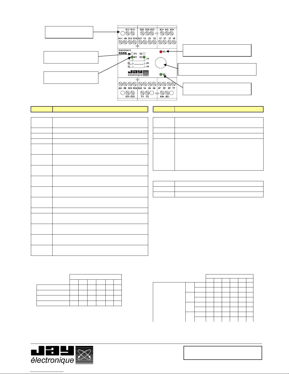
6.2 Faults communicated by receiver
To indicate faults, the receiver uses 4 indicator lights, V1 to V4.
The 2 white indicator lights, « V1 and V2 », indicate the status of the receiver safety functions.
The red and green indicator lights, « V3 and V4 », indicate the status and processing of radio signal reception.
V1 status
V2 status
Error detected
Cause(s)
Action(s)
On steady
Off
None
Handle on charger
None
On steady
On steady
None
Handle active
None
On steady
1 flash
Reset fault
Reset not done
Place handle on charger and
activate reset button on control panel
“Handle on charger” contact open or
wiring of contacts has been reversed
Check wiring of 2 handle presence
contacts
Radio link between handle and receiver
not established (V4 off)
Perform a scan to check that handle
and receiver are on same frequency
channel. See section “Frequency
channel selection”
In "area access" mode, gate passage
button on handle has not been
released following gate passage
request.
Place handle on its charger and
activate reset button on the control
panel to cancel error
Off
Off
Communication
problem
Problem internal to product
Return to factory
On steady
2 flashes
Protection inactive
Emergency stop button(s) locked or
gate contacts open
Check condition of buttons and
contacts, and wiring
On steady
3 flashes
Time delay error
Contacts of a safety component
(emergency stop or gate) have not
been activated in required time frame
- Close its contacts simultaneously.
- Place handle on its charger.
- Press reset button.
Once removed from its charger, handle
has not been started up within a
sufficiently short time (T0 > T defined
by 2 “A” selectors)
Repeat handle start-up procedure or
increase handle pickup time delay
On steady
4 flashes
Reset button fault
Contact on reset button has remained
closed
Check condition and type of reset
button contact (pulse type
pushbutton)
Off or 5 flashes
Off or 5 flashes
Adjustment error
« A » or « B » selectors not aligned on
same position.
« Off » status or « 5 flashes » status
depends on whether selectors have
been set with power on or with power
off
Switch off receiver power supply and
check position of A and B selectors
On steady
6 flashes
Charger contact
error
At least one of the charger contacts
has remained closed at moment the
was started up
Check condition of charger contacts
(NO contacts, handle off charger)
6 flashes
Off
Under-voltage
6 flashes on V1: Receiver power
supply voltage is less than 0.85Un
Check receiver power supply
Off
6 flashes
Over-voltage
6 flashes on V2: Receiver power
supply voltage is greater than 1.15Un
Page 36

Doc ref. : 332190D – EN
28.04.2014
Page 36 / 49
Off
7 flashes
Error on input(s)
One of the emergency stop inputs is
incorrectly wired
Check wiring of emergency stop or
gate inputs
8 flashes
8 flashes
Safety relay error
One of safety relays K1 or K2, or
associated control circuit, is faulty
Return to factory
Off
8 flashes
Safety relay error
Return loop to terminals Y1-Y2 not
closed when safety outputs are inactive
Check loop Y1 and Y2 and contacts
of external relays K3, K4.
Off
9 flashes
Relay K1-K2 error
Control circuit of one of the safety
relays is faulty
Return to factory
Off
10 flashes
11 flashes
Program error
An error has occurred during execution
of program
Return to factory
Off
12 flashes
Version error
Software versions of the 2
microprocessors are different
Return to factory
Off
13 flashes
14 flashes
Memory error
Memory is faulty
Return to factory
6.2.1 V3 and V4 LED status
The V3 (red) and V4 (green) led states describe a malfunction in the radio part of the safety receiver.
Name of Led
and colour
Mode
Indication
Message
State
V3
indicator light
(RED)
Normal
Indicates validity of
identity code
Message not received
OFF
Message received with
correct identity code
OFF
Message received with
incorrect identity code
Flashing
regularly
Serial link
ON
In case of
fault
Indicates a fault
Power supply error
2 flashes
Safety relay
3 flashes
EEPROM
4 flashes
RAM
5 flashes
ROM
6 flashes
Micro type
7 flashes
V4
Indicator light
(GREEN)
Normal
Indicates radio
reception quality
No radio reception
OFF
Bad radio reception
Flashing
Good radio reception
ON
Serial link
OFF
In case of
fault
Indicates a fault
Power supply error
2 flashes
Safety relay
3 flashes
EEPROM
4 flashes
RAM
5 flashes
ROM
6 flashes
Micro type
7 flashes
Page 37

Doc ref. : 332190D – EN
28.04.2014
Page 37 / 49
7 Servicing
BEFORE PERFORMING ANY MAINTENANCE OPERATION, MAKE SURE THE RECEIVER AND CHARGER
POWER SUPPLIES ARE CUT OFF.
7.1 Servicing the wireless enabling handle
The handle can only be disassembled by properly trained personnel working in a “controlled” environment; parts must only
be replaced by genuine, identical spare parts.
The user’s attention is drawn to the risks involved in using the handle in an environment containing polymer solvents or
glues which could impact correct operation of the mechanical components of the handle.
Clean the enabling handle by eliminating any foreign matter which may be sticking to the handle.
Do no use any aggressive cleaning agents. Use only a soap solution when cleaning the handle.
7.2 Servicing the charger
Check that the handle charging receptacle is clean and dry.
Do no use any aggressive cleaning agents. Use only a soap solution when cleaning the handle.
8 Maintenance
The level of accessibility to the spare parts will depend on the level of training of the end user:
Level 1 : Spare parts not requiring any tools or special know-how. Example : Battery, handle front panel, SIM card,…
Level 2 : Level 2 spare parts are only accessible to customers who have completed a level 2 training course, and to the
JAY Electronique service stations.
8.1 Setting a backup handle into service
Step 1 : Open the broken or faulty handle.
If the handle has been lost or is not available, reprogram a SIM card using the dialog RSP software (see installer if
necessary).
Step 2 : Remove the SIM card and install it in the backup handle.
Step 3 : Close the backup handle.
Step 4 : Have the faulty handle repaired.
8.2 Replacing a receiver.
Step 1 : Cut off the power supply
Step 2 : Disconnect the removable terminals on the receiver
Step 3 : Program the new receiver identically to the faulty receiver (see position of A and B selectors accessible under the
window on the front panel of the receiver.
Step 4 : Connect and supply the new receiver.
8.3 Replacing a charger.
Cut off the power supply and disconnect outputs S1 and S2
Associate the new charger to the handle. See section « Setting the charger into service »
Page 38

Doc ref. : 332190D – EN
28.04.2014
Page 38 / 49
9 Warranty
All our devices are guarantied 2 years as of the date of manufacture indicated on the product (except for the
enabling handle battery which has 1 year warranty). No repair, modification or replacement of a product during the
warranty period can be understood as an extension of the warranty period.
Limits of warranty:
The warranty does not cover defects resulting from:
• Transport,
• False manoeuver or non-observance of connection diagrams when setting the equipment into service,
• Insufficient supervision or servicing, utilization not complying with the specifications detailed in the technical manual
and, as a general rule, storage, operation or environment conditions (atmospheric, chemical, electrical or other
conditions).
• Conditions not specified on order of the equipment.
The warranty shall not apply subsequent to any modifications or additions to the equipment performed by the
customer without written approval by JAYElectronique.
The JAY Electronique responsibility during the warranty period is limited to material and construction defects. This
warranty comprises repair in the JAY Electronique workshops or replacement, free of charge, of parts recognized to
be defective following expert inspection by the JAY Electronique Technical Department.
The warranty shall not give rise to any compensation for damage claims.
Any disputes relative to a supply or settlement thereof shall be ruled by the COURT OF COMMERCE OF
GRENOBLE, solely competent, even in the event of an Appeal or a plurality of defendants.
Page 39

Doc ref. : 332190D – EN
28.04.2014
Page 39 / 49
10 Appendices
10.1 Dimensions of components (mm)
Wireless enabling handle RSEP Charger RSCP
Receiver RSRB Infrared module UDF
(for "IR start-up" option)
Plug-in BNC antennas Voltage adapter RSCU 230VAC/24VDC
Page 40

Doc ref. : 332190D – EN
28.04.2014
Page 40 / 49
10.2 Technical characteristics
10.2.1 Wireless enabling handle RSEP
Mechanical and environment withstand characteristics
Housing material : Two-material plastic
Protection index : IP 54
Weight (with battery) : 340 g
Operating temperature range : -20 °C to + 50 °C
Storage temperature range : -20 °C to + 45 °C
Charging temperature range : 0 °C to + 35 °C
Electrical and radio characteristics
Power supply : Li-Ion battery
Endurance (at 25°C) :
Trigger activated : 8 hours
Trigger not activated : 40 hours
Complete charge duration : 6 hours
Radio transmit frequencies :
(Interval between adjacent channels : 0.025 MHz)
RSEP40 : 64 frequencies, from 433.100 MHz to 434.675 MHz
RSEP41 : 25 frequencies, from 434.075 MHz to 434.675 MHz
Transmit power : <10 mW
Average range in typical industrial environment (1) :
RSEP40 : 150 m
RSEP41 : 250 m
Functional characteristics
Display : Backlighted LCD
Function button type :
4 single-acting pushbuttons
Trigger : 3 or 2 positions
Range limitation : configurable
Indications :
Radio channel, battery level, diagnostic, displayable on enabling handle screen
Configuration of functions and display :
Configurable by PC software
(1)= Range will vary according to environment conditions of enabling handle and receiver reception antenna (frameworks, metal partitions, … ).
10.2.2 Charger RSCP
Mechanical characteristics
Housing material : Plastic
Protection index : IP 40
Electrical characteristics
Power supply voltage : 24 V DC +/- 5%
Consumption when charging : 300 mA
Contact (handle detection) : 2 NO / 8 A
Handle detection : by infrared (contactless)
Type of charge : by induction (contactless)
Page 41

Doc ref. : 332190D – EN
28.04.2014
Page 41 / 49
10.2.3 Receiver RSRB
Mechanical and environment withstand characteristics
Housing material : Plastic
Protection index : IP 40
Weight : 500 g
Operating temperature range : 0 °C to + 50 °C
Storage temperature range : - 30 °C to + 70 °C
Connection : Screw terminals for wires 0.08² to 2.5²
Antenna : 1/4 wave, as accessory, plug-in on BNC connector
Electrical characteristics
Power supply voltage : 24 V DC +/- 15%
Max. consumption : 120 mA (solid state outputs not loaded)
Safety relay outputs :
Contacts : 3 NO with guided contacts
Triggering time (reaction) :
• Active stop time following clenching or release of trigger : 50 ms
• Passive stop time : 300 ms
Max. switching voltage : 250 V AC
Switching power :
• Per AC 15 : AC 3 A / 230 V for NO contacts EN60947-5-1
• Per DC 13 : DC 8 A / 24 V at 0.1 Hz EN60947-5-1
Electrical service life :
• Per AC15 at 2A, AC230V : 100 000 cycles EN60947-5-1
Solid state outputs :
Number and type of outputs : 6 PNP outputs
Output voltage : 24 V DC, 100 mA max.
Indication : 6 indicator lights
Page 42
Doc ref. : 332190D – EN
28.04.2014
Page 42 / 49
10.3 Indicator lights and assignment of receiver outputs
Terminal
Function
Terminal
Function
Safety inputs and outputs
Solid state outputs assigned to enabling handle
A1+
24VDC power supply for receiver safety
module RSRB
A3+
24VDC power supply for solid state outputs
assigned to enabling handle
A2 -
Common ground
A2-
Common ground
48
24V solid state output : safety module status
17
enabling handle on charger indication
58
Enabling handle utilisation status
27
37
47
57
67
77
Function outputs (see detail below)
S11
S12
Input 1 for first emergency stop or first safety
light barrier
S13
S14
Input 2 for first emergency stop or first safety
light barrier
S21
S22
Input 1 for second emergency stop or second
safety light barrier
S23
S24
Input 2 for second emergency stop or second
safety light barrier
Connection for infrared module (UDF)
A5+
12VDC output
S31
S32
Input for monitoring of 1st charger
IR
Receiver signal
A2-
Common ground
S33
S34
Input for monitoring of 2nd charger
S42
Input for wired START pushbutton
Y1
Y2
Input for auxiliary relay return loop
13
14
1st safety output (NO contact)
23
24
2nd safety output (NO contact)
33
34
3rd safety output (NO contact)
«4 control buttons» mode (on delivery) «Function selection» mode
In this mode, the outputs are activated as follows : In this mode, the outputs are activated as follows
Removable connection
block, screw terminals
White ind. lights V1 and V2
"Safety module status"
Green ind. lights K1 and K2
"Safety relay status"
Red ind. light V3
"Wrong identity code or diagnostic"
BNC connector
For antenna extensions and BNC antennas
Green ind. light V4
"Radio reception quality"
Receiver RSRB outputs
27
37
47
57
67
77
Function
selection by B3
and B4
F1
B1
X X
B2
X X
F2
B1
X X
B2
X X
F3
B1
X
X
B2
X
X
F4
B1
X
X
B2
X
X
Receiver RSRB outputs
27
37
47
57
67
77
B1
X X
B2
X X
B3
X X
B4
X X
Page 43

Doc ref. : 332190D – EN
28.04.2014
Page 43 / 49
10.4 «IR start-up» option
The start-up zone for an equipment, and the equipment’s identification, can be secured by an IR validation on start-up.
To start the equipment, the operator must be inside the IR transmit zone of the UDF module (referred to as the «Startup zone») and actuate the trigger on the handle.
Once the validation has been performed, the «Handle/Equipment to be controlled» pairing takes place with no
possibility for error. The operator can then move around freely with no limitation.
The range of the IR start-up field of action is 0 to 3 m (see below).
The interconnect cable between the UDF and the RSRB can be extended by up to 2x10m for a total of 30m (the
original UDF-RSRB link being 10m) using an accessory (referenced UDWR10) comprising a shielded cable and its
connector.
10.4.1 Positioning the IR module UDF
10.4.2 Connecting the UDF module to the receiver
Black : A2White : A5+
Blue : IR
IMPORTANT : The UDF module cables must be kept separate from the power cables and all other interference
generating sources (power regulator, for example).
Page 44

Doc ref. : 332190D – EN
28.04.2014
Page 44 / 49
11 Procedures
11.1 Accessing a machine area in « monitoring - diagnostic » mode
The enabling handle is on its charger and the machine is in service. The green indicator light on the indicator light
column is on steady.
Remove the handle from its charger.
The orange indicator light on the indicator light column flashes (duration programmed by « A » selectors on
safety receiver).
Activate the trigger on the handle within the time delay selected.
The green and orange indicator lights on the indicator light column come on steady.
Area entrance request by a gate :
Without releasing the trigger, transmit a request for entrance into the area through the gate (by pressing B1 or
B2). The orange indicator light on the indicator light column flashes (duration programmed by « A » selectors
on receiver).
Open the gate and close it within the muting time programmed for the gate. (Duration programmed by “A”
selectors on receiver).
Once the door is crossed and closed, orange and green lights on the indicator light column come on steady
again. The trigger on the handle will be maintained throughout the “monitoring – diagnostic” phase of the
equipment.
Area exit request by a gate :
Without releasing the trigger, transmit a request to «exit the area» through the gate (by pressing B1 or B2).
The orange indicator light on the indicator light column flashes and the green indicator light remains on steady.
Pass through the gate and close it within the gate muting time programmed.
Without releasing the trigger, present the handle in front of the charger.
The orange indicator light on the indicator light column flashes.
Release the trigger on the handle.
Place the handle on its charger.
The orange indicator light on the indicator light column goes off and the green indicator light remains on
steady.
Note: This procedure is the same whether the area is protected by a safety light barrier.
Page 45

Doc ref. : 332190D – EN
28.04.2014
Page 45 / 49
11.2 Accessing a machine area in « manual » mode
Preamble
In "manual" mode, the safety relay of the receiver will be wired so as not to cause an emergency stop, but a "cycle
stop" of the machine.
In this mode, the enabling handle is used to make an adjustment or a test of the machine after a maintenance
operation.
Area entrance request by a gate :
Stop the machine from the control panel to conduct the intervention.
Remove the handle from its charger.
The orange indicator light on the indicator light column flashes (duration programmed by « A » selectors on
receiver).
Without releasing the trigger, transmit a request for entrance into the area through the gate (by pressing B1 or
B2). The orange indicator light on the indicator light column flashes (duration programmed by « A » selectors
on receiver).
Open the gate and close it within the muting time programmed for the gate. (Duration programmed by “A”
selectors on receiver).
The gate will be closed to prevent the intervention of a third party and in order to use the handle in "manual"
mode on the machine.
Intervention on the machine :
Once in machine area, release the handle trigger if the maintenance work request to have 2 hands available.
Once the maintenance work completed on the machine, control the machine in manual mode using the
function buttons on the handle.
Note: If a third party opens the gate access during the intervention, it will be necessary to put the handle on its charger
to activate again the handle.
Machine area exit request by a gate :
Enable the trigger and make a request "out of area" by the gate (pressing B1 or B2).
The orange indicator light on the indicator light column flashes and the green indicator light remains on steady.
Pass through the gate and close it within the gate muting time programmed.
Without releasing the trigger, present the handle in front of the charger.
The orange indicator light on the indicator light column flashes.
Release the trigger on the handle.
Place the handle on its charger.
The orange indicator light on the indicator light column goes off and the green indicator light remains on
steady
Note :
This procedure is the same whether the area is protected by a safety light barrier..
This procedure does not apply if the machine area access by a gate or a safety light barrier is not controlled
by the receiver of the enabling handle. In this case, the handle is simply removed from its charger and used to
control the machine in manual mode.
Page 46

Doc ref. : 332190D – EN
28.04.2014
Page 46 / 49
12 Environmental data
According to EN 60947-1:2007 +A1:2011 clause 5.3, page 61:
NOTICE : This product has been designed for environment A. Use of this product may cause unwanted
electromagnetic disturbances in which case the user may be required to take adequate mitigation measures.
The altitude does not significantly affect the characteristics of RSRC receiver up to 2000 m. At higher altitudes, it is
necessary to take into account the reduction of the dielectric strength and the cooling effect of the air (EN 60947 -5-1).
The table below shows the corrections to be made depending on the altitude for the relay contacts. The breaking
capacities remain unchanged. According to EN 60664-1 :
Altitude [m]
0
200
500
1000
2000
Lightning impulse withstand voltage [kV]
7.4
7.2 7 6.9
6
The relative humidity of the air does not exceed 50 % at a maximum temperature of +40°C. Higher relative humidities
may be permitted at lower temperatures, e.g. 90 % at + 20°C.
13 Residual risks
The product being an element of the equipment, a risk analysis of the concerned application will allow to estimate
these residual risks.
14 Foreseeable misuse
Polarity inversions of the safety receiver power supply : no starting up of products.
Other misuse of the wireless enabling handle RSEP : see Diagnosis paragraph.
Other misuse of the safety receiver RSRB : see Diagnosis paragraph.
15 Contraindications
The wireless enabling handle RSEP should be changed after 233 hours of use.
16 Waste recycling and management
When the unit has reached the end of its service life, be sure to dispose of it appropriately. The
unit can be disposed of in a specific waste collection centre as organised by the local
authorities, or it can be turned over to a distributor who will handle proper disposal of the unit.
Electronic waste sorting will prevent possible negative impact on the environment resulting from
inappropriate elimination of electronic waste and will allow proper processing and recycling of
the materials forming the unit, representing signifi cant savings in terms of energy and
resources.
17 Manufacturer information
Head office and plant :
ZAC la Bâtie, rue Champrond
F38334 SAINT ISMIER cedex
Tel : +33 (0)4 76 41 44 00
Fax : +33 (0)4 76 41 44 44
www.jay –electronique.com
Page 47
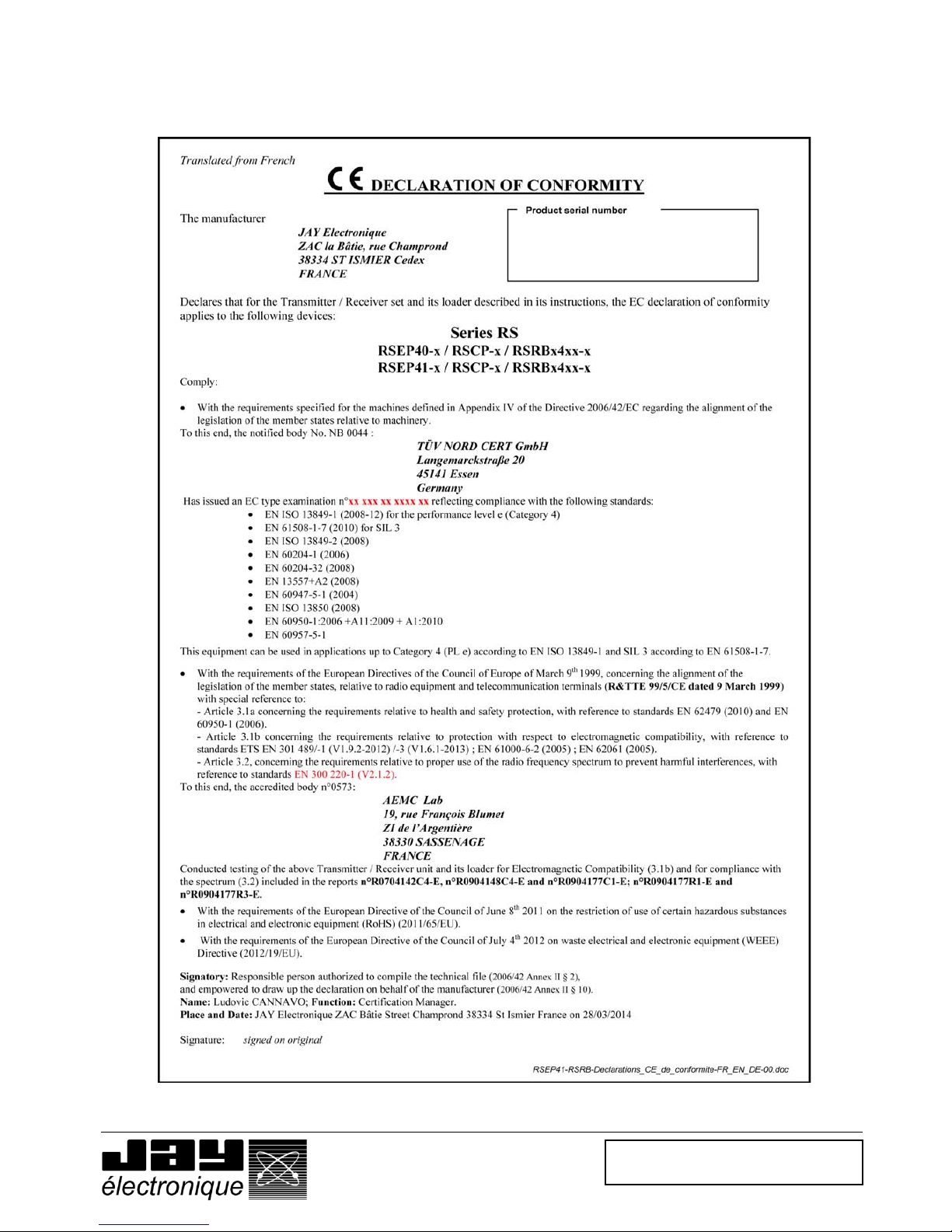
Doc ref. : 332190D – EN
28.04.2014
Page 47 / 49
18 CE Declarations of conformity
18.1 RSEP40-x / RSCP-x / RSRBx4xx-x and RSEP41-x / RSCP-x / RSRBx4xx-x
Page 48

Doc ref. : 332190D – EN
28.04.2014
Page 48 / 49
18.2 RSEP4A-x / RSCP-x / RSRBx4xx-x and RSEP4B-x / RSCP-x / RSRBx4xx-x
D.d
Page 49

Doc ref. : 332190D – EN
28.04.2014
Page 49 / 49
IMPORTANT
When the wireless enabling handle is placed on its charger, radio transmission is
stopped and its trigger is INACTIVE !
RS
Appendix to installation manual 332190D
Ok
Equipment operating
In area
Intervention in area with handle
Stop
Equipment stopped and secured
 Loading...