


1
Specification and
Operator's Manual
WITH SPECIAL REFERENCE TO SERVICING AND
ROUTINE MAINTENANCE OF MOTORCYCLES
YEZDI 250 cc MODEL ‘B’
JAWA 250 cc MODEL 353/04
Manufacturers
IDEAL JAWA (INDIA) PRIVATE LTD.,
MYSORE 570 002, SOUTH INDIA

2

3

4

5
INDEX
I SPECIFICATION AND OPERATOR'S MANUAL Page
1. Technical data 7
2. Description of motorcycle 10
3. Electrical equipment description 13
4. Running a new motorcycle 18
5. Servicing instructions 20
6. What should be avoided 23
II MAINTENANCE
1. Cleaning the motorcycle 24
2. Lubricating the motorcycle 25
3. Adjusting the brakes 30
4. Tyres 30
5. Adjusting the chain 33
6. Adjusting the clutch 34
7. Carburettor 35
8. Electrical equipment maintenance 38
9. Decarbonisation 41
III DISMANTLING AND ASSEMBLING WITHOUT THE AID OF SPECIAL TOOLS
1. Removing the front wheel 43
2. Removing the rear wheel 44
3. Removing the chaincase and the chain 45
4. Removing the rear chainwheel 45
5. Replacing the wheel ball bearings 45
6. Removing the cylinder head and barrel 49
7. Replacing the piston rings 50
8. Removing the carburettor 50
9. Dismantling the clutch 51
10. Dismantling the headlamp 51
11. Dismantling the steering head and fork legs 53
12. Handlebars --- twist grip 55
13. Removing the dual seat 55
14. Removing the fuel tank 55
15. Removing the cowls 55
16. Dismantling the rear suspension 56
17. Pivoted Fork 57
18. Removing the battery 58
19. Dismantling the switch box 58
20. Removing the engine from frame 59
21. Removing the R.H. and L.H. engine covers 59
IV DEFECTS, CAUSES AND REMEDIES 60
Two-stroke engine operation 63

6
LIST OF ILLUSTRATIONS
1. JAWA 250 c.c. ... model 353/04 24. Removing the front wheel
1a. Yezdi Model 'B’ 25. Taking out the rear wheel spindle
2. Engine 250 c.c - sectional view 26. Dismantling the chaincase
3. Plan of the Motorcycle 27. Rear wheel brake drum ...
exploded view
4. Induction silencer - sectional view 28. Front wheel ... sectional view
5. Electric wiring diagram 29. Rear wheel ... sectional view
6. Stop switch 30. Disconnection the exhaust pipes
7. Oil filling and inspection hole 31. Removing the cylinder head
8. Fuel tap positions 32. Removing the cylinder barrel
9. Butterfly air valve 33. Fitting the piston rings
10.Lubrication chart - L.H. side 34. Front fork -- sectional view
11.Lubrication chart - R.H. side 35. Lubricating the steering head
bearing balls
12.Draining the gearbox oil 36. Lubricating the steering head
bearing balls
11.Removing the chain 37. Adjusting the twist grips
connecting link 38. Removing the dual seat
14.Adjusting the brake 39. Disconnecting the rear suspension
damper top bracket
15.Rim and tyre - sectional view 40. Pivoted rear fork bushing -- sectional
--fitting the tyre cover 41. Removing the battery
16.Correct tyre fitting 42. Two-stroke engine operation diagram
17.Adjusting the chain
18.Chaincase lid
19.Clutch operation diagram
20.Adjusting the clutch
21.Carburetter, flange type
22. Removing the fuse
23.Exhaust silencer - sectional view

7
TECHNICAL DATA
1. TECHNICAL DATA 250 c.c Model 353/04
------------------------------------------------------------------------------------------------
Engine Two-stroke, air-cooled
Number of cylinders One
Bore 65 mm
Stroke 75 mm
Cylinder capacity 248.5 c.c.
Compression ratio 7.2 to 1 (YEZDI - 7.6 to 1)
Engine output 12 BHP (YEZDI - 13 BHP)
Fuel consumption at steady 60 km.p.h 3 litres/100 km
(37 m.p.h) (93 m.p.gallon)
Fuel tank capacity 13.5 litres (Jawa); 14.5 litres (Yezdi)
Maximum speed 105 km.p.h
(65 m.p.h)
Maximum climbing ability (fully laden) 45%
Dimensions of motorcycle --length 1980 mm
--height 1025 mm
--width 670 mm
Weight of motorcycle --dry 128 kg (Jawa); 131 kg (Yezdi)
--inc. fuel 140 kg (Jawa); 144 kg (Yezdi)
Carrying capacity (payload) 160 kg
Front wheel spindle maximum load 85 kg
Rear wheel spindle maximum load 214 kg
Primary drive of 3/8 x 3/8 in. chain 60 links
Final driver by 1/2 x 5/16 in. chain 120 links
Primary and final drive ratios:
Primary 45/22 T
Final 46/19 T
Bottom gear 24/12 x 19/12
Second gear 20/16 x 19/12
Third gear 17/19 x 19/12
Top gear 1/1 direct
Overall gear ratios:
Bottom gear 15.675 to 1
Third gear 9.800 to 1
Second gear 7.013 to 1
Top gear 4.952 to 1
Overall kickstarter ratio 3.41 to 1
Speedometer drive ratio 5/11 T
internal expanding brakes dia 165/35 mm
Braking distances from 40 km.p.h
(25 m.p.h) front wheel brake 30.8 m. (101.05 ft.)
rear wheel brake 30.8 m. (101.05 ft.)
both brakes applied 12.5 m. (41.01 ft.)
Front fork maximum stroke 130 mm (51/3 in.)
Pivoted rear fork maximum stroke 100 mm (3 15/16 in.)
Carburettor 2926 SBD
wheels Interchangeable
size of rims 1.85 B x 16 in.
size of front tyres 3.00 or 3.25 x 16 in.
size of rear tyres 3.25 x 16 in.

8
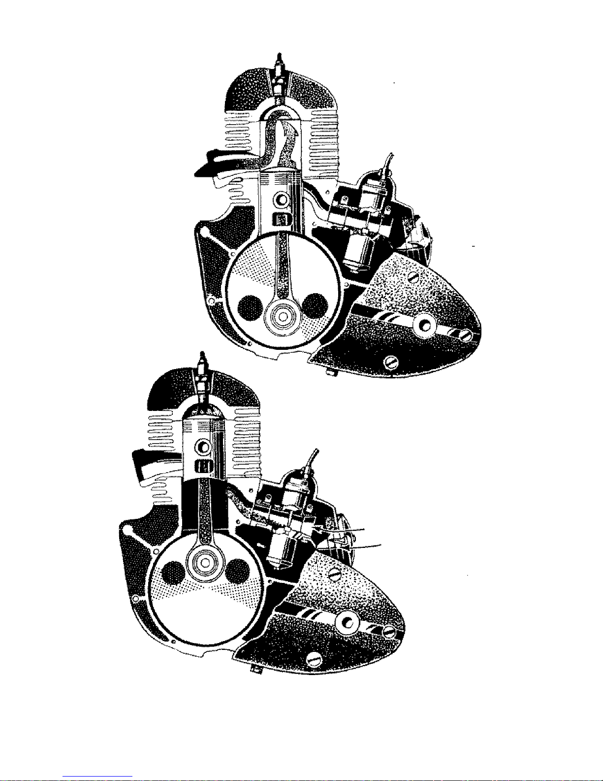
Fig. 2. Engine 250 c. c.- sectional view

9
Fig .3. Plan of the Motorcycle

10
2. DESCRIPTION OF MOTORCYCLE
The 250 c.c is a solo motorcycle suitable for carrying one or two persons.
The power unit is a two-stroke, air-cooled petrol engine with inverted scavenging.
The engine has a quiet run, well balanced within its extent of revolutions, without
vibration and is capable of lively acceleration.
The clutch is a five-plate friction clutch, fitted with cork lined steel plates running
in an oil bath. Clutch control by hand lever fitted on L. H. side of the handlebars.
The gearbox is of the four-speed type, forming with the crankcase a monoblock
engine unit.
The gear shifting is foot operated by means of a lever located on the L. H. side of
the engine. When changing gear, the declutching is automatic.
Fig. 4 Induction silencer - sectional view
1. Induction silencer cover 5. Clamp
2. Air cleaner 6. Rubber sleeve
3. insert 7. Butterfly air-valve
4. Silencer body 8. Fastening strap
The starting of the engine is foot operated by means of the same lever as gear
shifting and is effected by depressing the shaft and rotating the lever into the
starting vertical position. As soon

11
as the engine starts running the lever returns automatically into the horizontal
position.
The power transmission is by means of chains. The primary chain is enclosed
by the L.H. crankcase cover and runs in oil bath. The final or secondary drive
chain which connects the gear box sprocket to the rear chain wheel is also fully
enclosed by means of a chain case and this arrangement makes the chain last
much longer. The rear chain wheel is coupled with the wheel (brake-drum) by 6
large rubber blocks fitted on the lugs of the chain wheel and engaging into the
chambers (ribs) cast in the brake-drum face. These rubber blocks also act as
efficient dampers, absorbing practically all the shocks of the power and
transmission units and has a very favourable influence on the life of the chain as
well as the vital engine parts (giving the vehicle a smooth CUSHION drive).
The spoke wheels are interchangeable and easily detachable - the spindles being
of the push-out type. The number of spokes is 36 in each wheel - the spoke dia
being 3.5 mm - thread M4.
The brakes are of full width hub and very efficient. The fins along the brake-drum
circumference greatly facilitates in the transfer of heat resulting from braking and
contributes to unchanged braking efficiency during continuous braking and on
long runs. The front brake is controlled by hand lever fitted on the right hand side
of the handle bars, and the rear brake by foot lever located on the right hand side
of the engine. Brakes are easily adjustable without the aid of any tools.
The frame is built up of square section welded tubes with a pivoted rear fork.
The fuel tank is a sheet steel pressing. It is fitted, with a filler cap dia. 60 mm
(2.36 in.), and a fuel tap with filter, It has an emergency fuel reserve of approx. 1
litre (l pts.).
The dual seat with foam-rubber padding is very comfortable. Together with the
rear suspension it offers a superior ride to both driver and the passenger. The
dual seat is detachable and covers an auxiliary box for tyre inflator and spare
parts.

12
The handlebars of 22 mm (55/64 in.) outer diameter have a width of 670 mm
(263/8 in.). They are of one piece, the clutch and front brake cables being
adjustable by means of grub screws at the handlebar levers.
The front suspension consists of a telescopic fork with hydraulic dampers. It is
of the straight slider type with two cylindrical coil springs. The suspension
elements are protected by steel cover tubes. In the top portion of the front fork
stanchion tubes air valves are fitted through which compressed air escapes at the
down-stroke of the suspension.
The rear suspension operates on a circular path. The pivoted rear fork is sprung
by two cylindrical coil springs and fitted with hydraulic dampers. The suspension
dampers are protected by chromium plated steel covers.
The motorcycle could be 'locked by means of an ordinary pad-lock. A bracket has
been located for this in the L. H. side of the steering head, and the motorcycle
could be locked after completely turning the handlebars to the right.
List of Tools: -
Tyre lever with hook Spanner
Tyre lever
Double Ended Spanner 22/19
Double Ended Spanner 17/14
Double Ended Spanner 13/12
Double Ended Spanner 10/9
Double Ended Spanner 7/6
Combined Spanner 32/22
Tube Spanner 10 mm
Tube Spanner 14 mm
Tube Spanner 17 mm
Tommy Rod
Screw Driver 1
Tool Kit -Bag

13
3. DESCRIPTION OF TECHNICAL EQUIPMENT
Ignition and lights are effected by an A. C. Magdynamo. The magdynamo is a
small alternator in which rotor (permanent magnet) while rotating in fixed coils of
the stator induces the current required for the ignition of the mixture as well as
for the lights and the charging of the battery. The three circuit system is arranged
so that the ignition and the headlamp main beam are supplied direct from the
magneto alternator, whereas the battery serves exclusively as an auxiliary source
for the parking light, the tail lamp, stop light, horn and also to facilitate easy
starting.
The magneto stator is secured by two M6 bolts and clamps to the crankcase. The
entire housing can be rotated through 36 degrees for ignition advance setting. The
contact breaker complete is fitted on the stator. Its position on the stator is located
by the manufacturers by means of an Oscillograph to ensure most suitable
tension for ignition and lighting, and this position should never be altered under
any circumstances.
The terminal base fitted on to the stator has the following terminal numbers: -
Number 11 Voltage supply for Ignition
“ 20 Voltage supply for battery charging
“ 55 Voltage supply for Head Light
The rotor is fitted on to the Crank Shaft and held by a bolt together with the cam
controlling the contact breakers.
The battery-14 AML, 6V - with lead plates and electrolyte (diluted sulphuric acid)
is located in the L. H. side box and connected to the frame with its positive (plus)
pole. A 15 Amp. fuse is fitted in a case next to the battery.
A Rectifier (which converts the A. C. magneto current to D. C. for the charging
of the battery) is located on the battery box and is accessible after the dual seat
has been removed. It does not require any maintenance and any manipulation
whatsoever with it should be avoided.

14
The switch box is built into the headlamp and distributes the magneto and
battery current to the accessories.
The terminal plate (at the bottom) of the switch box has the following terminal
numbers
Number 11 for ignition - connected to terminal No. 11 of magdynamo base plate.
“ 15 For ignition connected to terminal No. 15 of H. T. Ignition coil.
“ 21 For battery charging connected .to terminal No. 21 of the rectifier.
“ 30 Connected to negative terminal of battery.
“ 30 Two leads from this terminal (1) to horn and (2) to stop light switch.
“ 55 For Head lights - connected to terminal No. 55 of magdynamo base
plate.
“ 56 For Head lights - connected to Dip switch on Handlebars.
“ 58 Two leads from this terminal (1) to parking light and (2) to tail light.

15
SWITCH KEY POSITIONS
POSITION 1
Engine not running. Key rammed or partly inserted. All appliances
horn and stop-light arc off. Day riding Key inserted. Ignition and
charging circuits commit & accept fully.
POSITION 2
Night riding in town. Key fully inserted Ignition and charging
circuits connected, Pilot Light and Tail Lamp on. Battery gets
charged at increased revolutions.
Patting: With the key removed both bulbs remain on, but the other
circuits are cut.
POSITION 3
Highway night riding. Key fully inserted, Ignition and charging
circuits connoted, the pilot light and Tait lamp are on. The Head-
lamp main bulb is supplied with current from magdynamo direct.
To switch from main beam to dipped beam, use dip-switch on
handle bars.
Battery gets charged at increased revolutions.
POSITION 4
Riding on battery. Key fully inserted, Ignition Coil connected with
the battery direct, the charging circuit connected
This position is to be used for easy starting only.
Battery discharges in this position and hence the key should be
switched on Position 1 after the engine starts.

16

17
Other Electrical Accessories:
The Head lamp is fitted with a 12V-35/35 W double filament bulb with Ba 20d
Socket. The pilot bulb 6 V - I.5 W with Ba 9s socket is also fitted in the head lamp.
Tail lamp bulb - 6 V 5 W
Stop light bulb - 6 V 8 W
The electric Horn 6 V - 2 Amps fitted under the head lamp is fed by the battery
and is operated by a push button on the dip switch.
The H. T. Ignition coil is fitted to the frame underneath the fuel tank.
The condenser of value - 0.2 mF is placed on the frame in the vicinity of
the ignition coil. The condensor lead is connected to terminal No. 1 of the ignition
coil.
The sparking plug used either MICO HB - W 175 Zi or KLG F70. The stop light
switch is located in the R. H. side tool box.
Fig. 6. Stop switch diagram
All connections are of varnish coated automobile leads.
The lead terminals are brass or soldered. The leads from magneto to switch box;
dip switch to main bulb; and sparking plug leads have 1.5 mm2 (0.002 sq. in) in
section and the remaining leads 1 mm2 (0.0015 sq. in.).

18
4. RUNNING A NEW MOTORCYCLE
When taking over a new machine and before making the first trip the customer is
advised to check the equipment of the motorcycle as well as the oil level in the
gearbox and in the front suspension dampers. The oil level in the gear box can be
checked by the oil level inspection hole closed by the oil level screw M6 x 8. For
filling up with oil see Part II, para 2, "Lubricating the Motorcycle". To check the
correct oil level in the hydraulic suspension dampers depress the front and rear
of the motorcycle in turn as much as possible, release quickly and check the recoil
for smooth, bounceless movement. Or ride for a short distance on a rough road
and check the front and rear suspension respectively for bouncing, knocking,
noise and rattle. It should be pointed out that the riding comfort on this type of
motorcycle depends above all on the proper operation of the hydraulic dampers.
A new motorcycle just as a new motor car requires careful running if the engine
is to attain a long life. Only with such running in it is possible to harmonize the
contact faces of all the moving parts smoothly so as to avoid local overheating of
the friction faces and possible damage to them.
It is thus clear that the basic condition of good running in is not to use high
engine power for given time, i.e. to keep the speed down according to the table
below and to observe the following instructions :
a) Mix oil with petrol in the approved ratio as follows ; During the running-
in period of first 1500 kms. (900 miles) at a ratio of 1 to 16, i.e. 62
millilitres of oil to one litre of petrol (1/2 litre of oil to 8 litres of petrol)
and thereafter at a ratio of 1 to 20, i.e. 50 millilitres of oil to one litre of
petrol (1/2 litre of oil to 10 litres of petrol).

19
The lowest and highest speeds in the individual gears for motorcycles not run-in
(i.e. to the mileage 1500 km. or 900 miles)
1st gear … … … 10 – 18 km. p.h.
(6 – 11 m.p.h)
2nd gear … … … 18 – 30 km. p.h.
(11-19 m.p.h.)
3rd gear … … … 25 – 42 km. p.h.
(16-26 m.p.h.)
4th gear … … … 35 – 60 km. p.h.
(22-37 m.p.h.)
b) Table showing speed to be maintained and carburetter setting with reference
to mileage.
Kms (miles)
covered
Tolerated
Maximum
speed
Carburetter setting
Needle
position
Pilot air screw
slackened by
Upto 1500 km.
(900 miles)
1500 km to 3000
km.
(900 to 1850
miles)
Over 3000 km.
(1850 miles)
60 km. p.h
(37 m.p.h)
75 km. p.h
(47 m.p.h)
not limited
4th notch
from top.
3rd notch
from top
3rd notch
from top
¼ turn
½ turn
½ turn
Note : During the running-1n period, the carburetters are set for a rather
rich mixture. It is necessary in the interest of fuel consumption to adjust
the needle position and the pilot air screw in the course of running in
accordance with the above table.
c) When slowing down to a stop keep the engine at idling speed.
d) Check periodically all screws and nuts for slackness and after covering approx.
200 km. (120 miles) tighten the spoke nipples. We are especially pointing out the
necessity to tighten well the engine fixing screws (2 in the front and 2 in the rear
- the rear screws are accessible after removing the L. H. side box).

20
e) Change the oil in the gearbox after the first 500 km. (300 miles). Repeat this
operation after 1500 km. (900 miles). See Part II, Para 2, "Lubricating the
Motorcycle".
f) After the first 1000 km. (600 miles) change damper oil in front fork dampers.
See Part II, para 2 "Lubricating the Motorcycle".
5. SERVICE INSTRUCTIONS
A. Before starting
Make sure there is fuel in the tank. Open fuel tank filler cap by turning it
anticlockwise. Keep filler cap breathing hole clean. After running in the
motorcycle mix oil with fuel at a ratio of 1 to 20 (at a ratio 1 to16 during the
running in period).
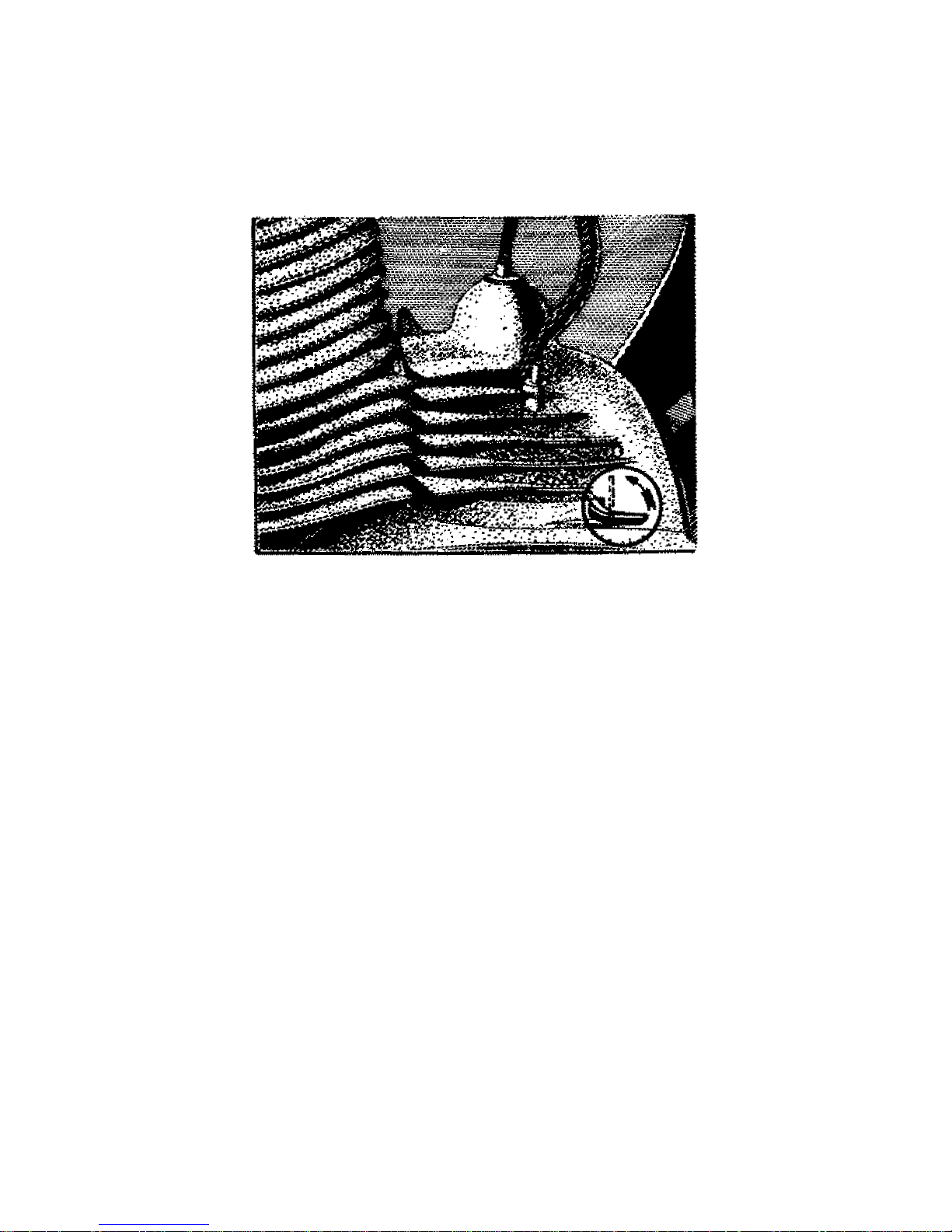
Fig. 7. Oil filling and inspection hole
The fuel tank is fitted with a lever type fuel tap. This fuel tap ensures an
emergency fuel supply for about 20 km. (12 miles), depending on the terrain and
speed. Should this fuel reserve be exhausted tilt the machine to the left thus
bringing the remaining fuel from the R.H. half of the fuel tank to L.H. half, i.e. to
the fuel tap. This last reserve will do for about 4 km. (2.5 miles).

21
Check the tyre pressure. The pressure in the front tyre should be 18 lbs. sq. in.
(1.25 atm.), in the rear tyre 21 lbs. sq. in. (1.5 atm.); when riding with pillion
passenger increase to 28 lbs, sq. in. (2 atm.).
Fig. 8. Fuel tap position
0. fuel shut off 2. fuel shut off
1. fuel main supply open 3. fuel emergency on
B. Starting the Engine
a) Check and see that the gear is in the neutral position (between the bottom and
the second gear).
b) Open the fuel tap. close the carburetter air intake by turning the air cleaner
strangler and flood the carburetter by pressing down the tickler pin. (Flooding
and air intake closing should be carried out only if the engine is cold).
e) insert ignition key into switch box.
d) With a slight pressure of the foot on the face provided on the gear change lever
hub press the lever towards the engine rotating it at the same time into the
starting position. Then start the engine by kicking the starter down. As soon as
the engine has started the lever returns automatically to its horizontal position.
if required the engine can be started with the gear engaged if the clutch lever is
depressed.
22
Note :
If the motorcycle has not been in use for a considerable period the clutch plates
may be stuck. It is recommended to test the clutch before starting the engine.
Engage the bottom gear, push the motorcycle and declutch two to three times. If
the clutch operation is correct shift to neutral.
Fig. 9. Butterfly air valve
(horizontal position - air open:
vertical position - air closed)
C. Riding
a) Depress fully clutch lever with your left hand, shift into bottom gear with your
left foot by pushing the foot gear change lever upwards and release the clutch
lever slowly while at the same time gradually opening the throttle. Should the
clutch cable be broken the motorcycle can be started by slowly releasing the gear
lever from the upper position. As soon as a speed of 15 km. (9 miles) is reached
close the throttle, push down the gear lever with your foot (engage second gear)
and reopen the throttle. Engage the other gears in the same manner. When
changing down the gear lever has to be lifted upwards. It is recommended to
declutch at the beginning before you get the feel at what speed to change down
without declutching.

23
It is pointed out that between the third and top gear is an unmarked neutral
position. Both the neutral positions are engaged by shifting the gear lever half
way between the two gears.
The lowest and highest speeds in the individual gears for run-in motorcycles:
1st gear … … … 10-25 km p.h
(6-16 m.p.h.)
2nd gear … … … 20-45 km p.h.
(12-28 m.p.h.)
3rd gear … … … 20-65 km p.h.
(20-40 m.p.h.)
4th gear … … … 40 km p.h. upwards
(25 m.p.h. onwards)
b) When slowing down to a stop, close the throttle, declutch, put on the brakes
and shift the gear lever into the "neutral position" between the bottom and second
gear. Only then release the clutch lever. During short stops (on corssroads, etc.)
shift the gear lever into bottom gear and keep the clutch lever depressed. When
braking, also use the front brake but a little later than the rear brake and only
when travelling straight on.
Having finished riding turn off the fuel tap, remove switch key and if required lock
the safety lock.
Having finished. riding for the day, let the engine run at low revolutions after the
fuel has been shut to consume the fuel in. the carburetter. The oil in the petrol
mixture deposits in the float chamber and might choke the jet.
5. WHAT SHOULD BE AVOIDED
To let the engine race while it is standing is harmful as it is not being cooled. Do
not keep it declutched for any considerable time as the cork inserts of the clutch
plates would be subjected to unnecessary wear, Never help the engine uphill by
letting the clutch "slip" but change down in time; do not ride for long with bottom
gear engaged

24
II. MAINTENANCE
1. CLEANING THE MOTORCYCLE
The simple smooth lines of the motorcycle make it easy to clean. Use plenty of
water for washing the machine, preferably with a sponge. Wash with paraffin
parts that have been soiled with oil and dust. When washing take care to keep
the carburetter, headlamp and brakes clear of water. Wipe dry enamelled and
chromium plated parts and polish them with flannel or chamois leather. The
enamelled parts can be polished with an enamel polish.
To remove the water from the cylinder cooling fins, start the engine, the warmth
of which will cause the water to evaporate.
Note: Petrol, paraffin and oil dissolve rubber (tyres, handlebar grips, footrests).
Consequently, protect the rubber parts from
Fig. 10. Lubrication chart - L. H. side

25
contact with the liquids mentioned. The tail lamp, made of polysterene. has to be
particularly protected from contact with the mentioned liquids which have a
damaging effect.
2. LUBRICATING THE MOTORCYCLE
The engine is lubricated automatically by adding oil to the fuel at a rate of 1:20
(in the ratio of 1:16 during running in period). Refill the gearbox oil after every
3,500 km. (2,000 miles). Change the oil preferably after having finished a trip
while both the engine and oil are warm. The warm oil will scavenge any
accumulated sludge.
The correct oil level in the gearbox is determined by the inspection screw, (fig. 7 bottom arrow). Check the oil level from time to time by unscrewing this screw and
top up, if necessary.
Fig. 11 Lubrication chart – R.H. Side
WARNING
In the interest of good engine performance and full engine life ENSURE that
popular brands of engine and gear box oils are used from Sealed Tins only.

26
Fig. 12. Draining the oil from the gearbox
The clutch runs in an oil bath (oil from the gearbox).
The telescopic front fork dampers: After the first 100 km. (600 miles) drain the
damper oil from both front fork legs after having first unscrewed the drain plug
(14). Remove the headlamp reflector and dismantle the headlamp top nacelle (see
Part-III, para 10) to obtain access to the top nuts (1) and unscrew them from the
fork tubes (3). After having drained the oil rinse both the fork legs thoroughly with
petrol (make the suspension play several times), drain the petrol and let it dry.
Having screwed in the drainplug (14) fill both fork legs with 175 c.c (of damper
oil.) No more oil changes are needed except in case of dismantling the front fork
or replacing a worn seal. It is recommended to check after every 2,000 km. (1,200
miles) (see Fig. 34)
The rear dampers: As compared to the former the new type dampers have
increased damping efficiency, and they are so designed that no topping up with
oil is required. It is recommended to have any possible repairs, cleaning the
interior etc. done in specialist workshop.

27
LUBRICATION CHART
Km
(Miles)
covered
Lubrication Point
Point
No.
Total
Type of lubricant
Instructions
Indian Oil Castrol Shell Esso
500 Control lever pins (front brake,
clutch)
3 2 Mobil
Oil
BB
G.P.50
X-100
Motor Oil
50
Motor
Oil 50 2,3 drops with oil can
1000 Gear Box 4 1 Mobil
Oil
BB
G.P.50
X-100
Motor
Oil 50
Motor
Oil 50 Top-up after checking with level screw
1500 Rear Fork Pivot (Yezdi Model
‘B’ only)
2 1 Mobil
Grease
M.P
G.L.
Grease
Retinax
‘A’
Multi
Purpose
Grease
5 to 6 strokes of Grease Gun
3000 (a) Contact Breaker Arm Pin
(b) Speedometer drive cable
7
9
1
1
Mobil
Oil
BB
G.P.50
X-100
Motor
Oil 50
Motor
Oil 50
(a) Smear after removing arm
(b) 2 drops with oil can
(a) Contact Breaker Felt
(b) Twist Grip
7
8
1
1
Mobil
Grease
M.P
G.L.
Grease
Retinax
‘A’
Multi
Purpose
Grease
(a) Smear little with screw driver
(b) Remove, clean, smear and replace
3500 Gear Box 4 1 Mobil
Oil
BB
G.P.50
X-100
Motor
Oil 50
Motor
Oil 50 Drain and refill
(a) Wheel Bearings
(b) Rear Chain Wheel Bearings 6 15
2
1
Mobil
Grease
M.P
Heavy
Grease
Retinax
‘A’
Wheel
Bearing
Grease
Remove wheels; clean; repack bearings and refit
5000 Secondary Chain 10 1 Mobil
Grease
M.P
Graphite
Grease
Retinax
‘A’
Multi
Purpose
Grease
Remove; wash in kerosene; dry; submerge in molten grease; allow
to set; wipe surplus grease and refit
(a) Brake cams
(b) Control Cables
11
14
2
4
Mobil
Oil
BB
G.P.50
X-100
Motor
Oil 50
Motor
Oil 50
(a) 2,3 drops with oil can
(b) Disconnect cables; clean; lubricate and refit
8000 (a) Steering Head Bearing Balls
(b) Foot Brake Lever Pin
(c) Centre Stand Pin
16
17
13
2
1
1
Mobil
Grease
M.P
Heavy
Grease
Retinax
‘A’
Multi
Purpose
Grease
(a) Loosen stem; clean balls; repack and re-tighten
(b) Remove; clean; smear and replace
(c) Remove; clean; smear and replace
When
necessary
(a) Telescopic Front Fork
(b) Rear Suspension (nonsealed type only)
5
12
2
2
Shockabsorber
oil (light)
Shockol Donax
‘A’
Shockabsorber
oil (light)
Drain, clean and refill: (a) with 175cc oil in each
(b) with 75cc oil in each
Always Engine 18 1 Mobil
Oil
BB
G.P.50
X-100
Motor
Oil 50
Motor
Oil 50
Mix with petrol in ratio 1:20 (1 litre oil 20 litres petrol)
IMPOTANT: During running-in period of first 1500 Kms ratio should
be 1:16

28
The pivoted rear fork: The pivoted rear fork pin is automatically lubricated with
oil from the gearbox.
Wheels (bearings) have to be lubricated with grease after removing the dust caps.
Lubricate the rear chainwheel bearing (see Part III, para 4), having first removed
the rear chainwheel.
The primary chain is totally enclosed by the L. H. crankcase cover and runs in
an oil bath. It does not require any attention. When badly worn it should be
replaced. When replacing the primary chain the clutch should be dismantled. (It
is recommended to have this operation done in a repair shop equipped with
suitable tools.)
The Secondary chain has to be serviced after every 8,000 km. (5,000 miles).
Having pulled out the chain wash it in paraffin. Let it dry and place it for about
three hours in a slightly warm lubricant. Take out the chain, let the lubricant
solidify and after removing the chaincase fit the chain. See Part III, para 3 Removing the chaincase, Removing the chain and Assembly.
Mag-Dynamo: After 3,000 km. (1,900 miles) remove the R. H. side crankcase
cover and with a few drops of oil lubricate the contact breaker arm pin. Care has
to be taken to ensure that no oil gets on to the contact breaker points. The felt on
the contact breaker base plate has to be soaked with grease.
The control cables (clutch, front and rear brake. throttle) should be lubricated
after every 3,000 to 5,000 km. (1,900 to 3,000 miles) with a few drops of oil.
The twist grip should be lubricated after every 3,000 km. (2,000 miles) with
grease after removing the twist grip from the handlebars. Unscrew the screw
holding the plug in the rubber grip and pull off the grip.
The speedometer drive cable should be lubricated with a few drops of oil every
3,000 km. (1,900 miles) after removal of the headlamp rim with reflector from the
headlamp (see Part III, para 10) and disconnecting the speedometer.
The steering head bearing balls should be lubricated with grease (see Part III,
para 11), at least once every 8000 km. (5,000 miles).
Note for YEZDI: The pivoted rear fork for Yezdi Model 'B' is lubricated with the aid
of a grease gun through the grease nipple provided on the LH, side of the
motorcycle- Refer; Lubrication Cheri for particulars and also Figure 10.

29
Fig. 13 Removing the chain connecting link
Fig. 14 Adjusting the brake

30
3. ADJUSTING THE BRAKES
The motorcycle full width hub brakes are well dimensioned and are fully shielded
against water penetration which would reduce their efficiency. The brakes require
only occasional adjustment when the brake shoe lining is worn (excessive brake
lever stroke).
The brakes are adjusted by turning the adjuster nuts. Having adjusted the brakes
check the wheels for free rotation. With the rear brake the stop switch has to be
adjusted as well - see pars 8.
4. TYRES
The life of the outer tyre cover depends on the inner tube air pressure in relation
to the load carried. As a rule the tyre has to be inflated so as to keep its original
shape even under full load. Running on under-inflated tyres will result in the
cover wall cord threads breaking.
Rim and tyre - sectional view - fitting the tyre cover
The pressure in the front tyre should be 18 lb. sq. in. (1.25 atm.), in the rear tyre
21 lb. sq. in. (1.5 atm.), with pillion rider 28 lb. sq. in. (2 atm.). It is advisable to
check the pressure with the tyre pressure gauge. It is a well known fact that the
tyre pressure increases during long rides in hot weather. In cold weather, on snow
or icy roads partly under-inflated tyres will be of advantage for better control of
the machine. In addition

31
attention is called to the fact that oil, petrol and strong sunshine are harmful to
the tyres. Examine the tyres from time to time and remove any foreign matter,
such as sharp gravel, glass etc., struck in the tyre pattern.
Check the tyre valves for leakage by unscrewing the valve cap and moistening the
valve. Should any bubbles appear, the valve is leaky. In such case tighten the
valve core (the slotted valve cap will serve for the purpose). Should the valve still
leak, screw out the valve core and replace it by a new one. It is advisable to keep
a couple of valve cores as spares. A punctured tube has to be patched. The tyre
cover will have to be removed in the following manner:
Unscrew the valve core and deflate the tube completely. Unscrew the nut securing
the valve to the rim. Lay the wheel in a horizontal position and press the tyre edge
well into the rim base at a point diametrally opposed to the valve. Using the tyre
levers slip the cover edge over the rim edge Take care not to pinch the tube and
thus damage it. Having slipped all the cover circumference over the rim edge press
the valve completely out of the rim base and remove the tube. Having screwed in
the valve core and inflated the tube partially the punctured spot will be best
located by plunging tube into water. Mark the punctured spot (e.g. with a copying
pencil), dry the tube and repair as follows:
Slightly rub the punctured spot with a piece of sand-paper. Smear the rubbed
spot with rubber solution. Allow the solution to dry and only then place the patch
after first removing its protective coating. Press the patch well to the tube,
especially at its edges. Powder the patch spot with French chalk (talcum powder)
to prevent the tube sticking to the inner walls of the cover at the spots where the
solution -was smeared. Examine the outer cover carefully and remove foreign
materials, if any.
Fitting the tyre
Inflate the tube partially, insert it into the cover. one edge of which has remained
in the rim, push the valve through

32
the rim hole and secure it by its nut (do not tighten). Slip on the cover side over
the rim edge beginning opposite the valves hold it in the rim recess and work with
tyre lever gradually on both sides towards the valve. Proceed carefully in order
not to damage the tube by pinching it between the cover and rim edges.
Tyre patching is an emergency remedy only during a trip when a nail has
punctured the tyre. For permanent repairs of tyres and tubes damaged by sharp
gravel or glass rely on vulcanisation by a repair shop.
Fig. 16 Correct tyre fitting

33
Fig. 17. Adjusting the chain
5. ADJUSTING T HE CHA IN
Slacken the rear wheel sp indle, i.e. the spindle securing nut on the L.
H. side and the chainwheel sleeve nut on the R. H. side (slightly tap the
spindle as well as the sleeve nut). Then slacken the chain tensioning front
lock nuts and tighten evenly the rear adjuster nuts. Never use force when
tightening these nuts so as to avo id dam aging th eir th reads. Having
adjusted the chain tension, retighten the tensioning locknuts properly
then the sleeve nut and finally the spindle securing nut.
Make s ure that the wheel s are in lin e. Ad just the rear bra ke as well,
for having moved the rear wheel the brake might be slightly in constant
operation, and check the stop switch. Check the chain tension every 1600
km, (1000 miles). Remove the chaincase lid and depress the chain. The
free movement should not exceed 2 cm. (3/4 in.) with the machine
laden.

34
Fig. 18. Chaincase lid
6. ADJUSTING THE CLUTCH
If it is found when riding that the clutch is slipping. the fault can be generally
remedied by turning the automatic clutch adjusting the screw (in the R.H cover
opening) by 1/6 or 2/6 to the left. It is recommended to adjust the hand and
automatic declutching more accurately from time to time in the following manner:
a) Screw the hand clutch adjusting screw on the handlebars slightly thus
releasing the clutch lever.
b) Clean with petrol or paraffin any dirt from the automatic clutch cam (6) and
the clutch roller (5).
c) With your left hand take hold of the automatic clutch roller (5) and move it
towards the cam and back.
d) If there is any movement, turn the automatic clutch adjusting screw (4) to the
right, until the space between the roller (5) and cam (6) is approx. 0.1 to 0.3 mm.
35
e) Adjust the hand declutching by means of the hand clutch adjusting screw on
the handlebars so that the handlebar clutch lever has a little free movement,
f) Smear both the automatic clutch cam (6) and the roller (5) slightly with grease.
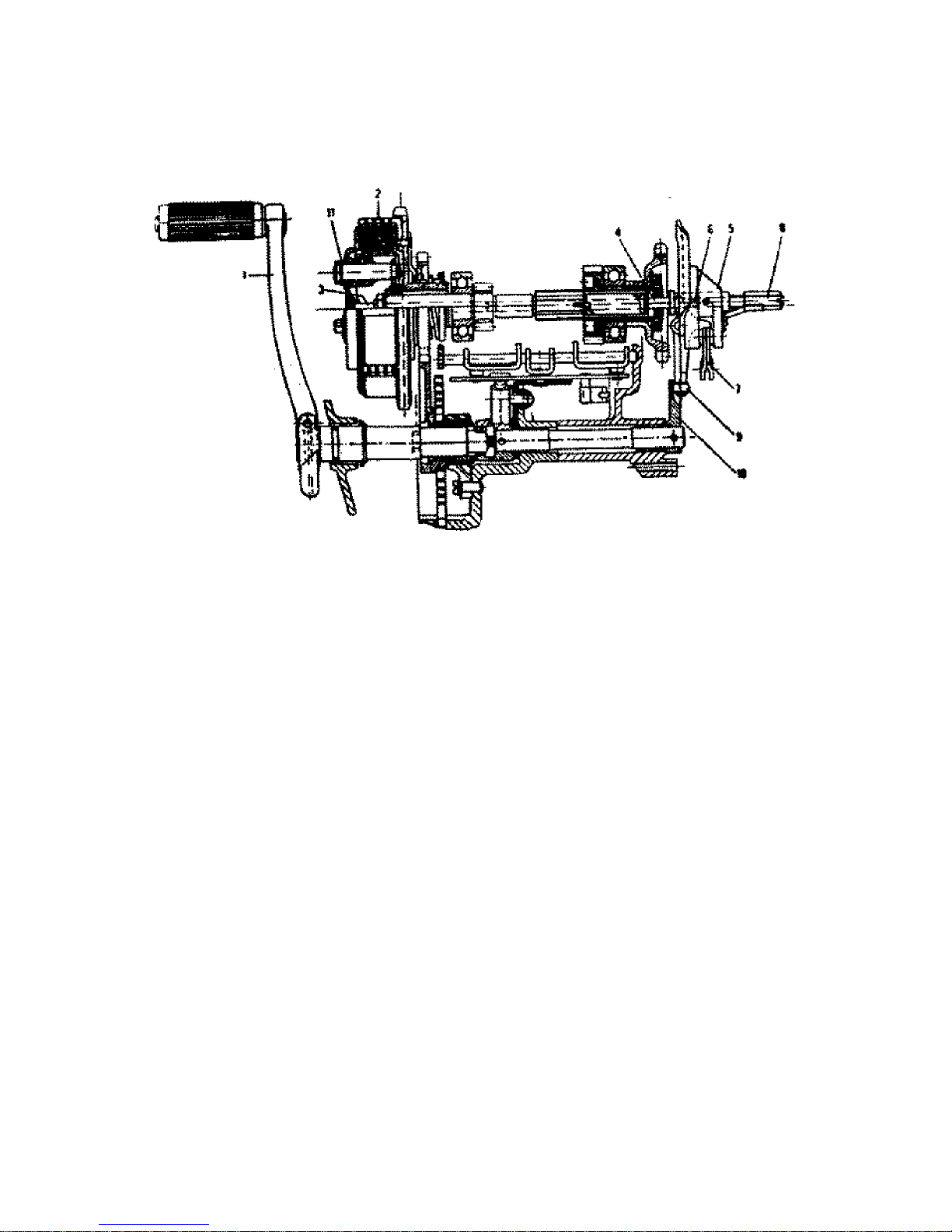
Fig. 19. Clutch operation (automatic) diagram
1. Foot gear change lever 6. Ball
2. Clutch 7. Clutch and lever
3. Clutch operating rod with thrust washer 8. Automatic clutch adjusting screw
4. Clutch operating rod 9. Automatic clutch roller
5. Clutch control carrier 10. Automatic clutch cam
11. Cup
7 CARBURETTER
The carburetter has been correctly set in the works. The jet and the throttle valve
have been selected by trail. Therefore, do not try to adjust the carburetter, clean
it only from time to time. To start the engine easily the idling speed has to be set
correctly. This is done by the pilot air screw. To obtain a poorer mixture, unscrew
it, to obtain a richer mixture, screw it in. With a poor mixture the engine is difficult
to start, has a tendency to back fire heats up and loses output. The exhaust pipe
acquires a slight colour tint. Too rich a mixture manifests

36
itself by heavy engine running, dark smoke coming out of the exhaust pipe, while
the inside of the carburetter becomes black.
Fig. 20 Adjusting the clutch
4. Automatic clutch adjusting screw 5. Automatic clutch roller
6. Automatic clutch cam
The idling speed of the engine (with fully closed throttle) can be adjusted by
extending or shortening of the throttle cable and by securing the throttle valve by
not letting it down to its bottom limit with the throttle valve screw (oblique screw
located on the carburetter body side). This screw should never be Completely
unscrewed.
To clean the carburetter dismantle it and wash the parts in clean petrol, Replace
damaged or worn parts. The idling

37
speed passages should be cleaned by passing a fine horse hair through them,
sever use wire or hard tools to clean the jet as this might damage the delicate jet
hole.
The Idling jet (2) is screwed in from the right above the pilot air screw (3). To
clean the jet unscrew screw (2) and blow the jet through.
The main jet of the carburetter is located in the bottom part or the needle jet. It
is accessible after unassembling of the carburetter and removing of the bottom
closing screw(1).
The induction silencer with air filter is accessible after the dual seat has been
removed.
VERY IMPORTANT :- To get the maximum benefit from the motorcycle, it is
strongly recommended that the metal air filter be removed and washed in clear
petrol every 1000 Km. It should then be moistened with thin motor oil and refitted.
This moistening is very essential as it will prevent fine dust particles from passing
through the filter and working its way into the engine and causing damage to the
vital working parts. Running on dusty roads makes more frequent cleaning of the
metal air filter necessary (preferably every 500 Km.), The air filter is accessible
after freeing the two securing clips and the air cleaner top.
It is necessary to check from time to time the hole connecting the compartment
under the carburetter with the space under the R. H. engine cover to see whether
it is not chocked and clean if required. The overflowing fuel from the carburetter
resulting from the carburetter flooding has to have possibility, to drain.
Note: The carburetter flooding just serves the purpose of rising the fuel level in
the float chamber and this (flooding) should be carried out slightly only to
facilitate starting when engine is cold. Otherwise it is quite unnecessary and at
times may result in the fuel overflowing into the induction silencer where there
are possibilities of its getting accidentally ignited.
38
Carburetter setting
Main
Jet
Idling
Jet
Needle
Position
Pilot air screw
slackened by
For running-in
92
45
4th notch
from top
½ turn
After running-in
92
45
3rd notch
from top
½ turn
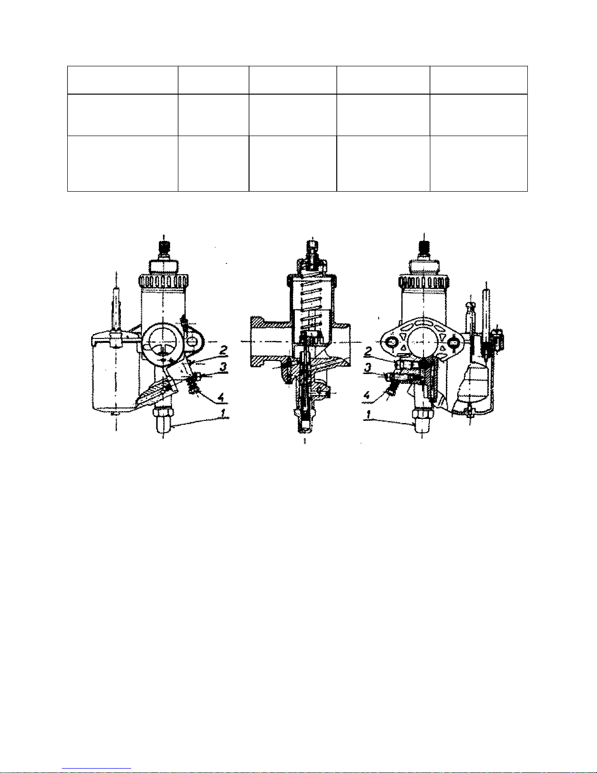
Fig. 21. Carburetter. flange type
Carburetter 1 - Closing screw
2926 SBD for the 250 c.c. model 2 - Idling jet
3 - Pilot air screw
8. MAINTENANCE OF ELECTRICAL EQUIPMENT
Examine the leads from time to time and wind insulating tape round insulation
cracks. Damaged insulating can cause short circuits possibly entailing serious
damage to the battery.
Clean the sparking plug periodically. Carefully scrape off any carbon deposits,
set the contact gap to 0.45 mm. (0.018 in.) by carefully bending the contact to the
plug body.
The fuse is located in a bakelite case in the L. H. box next to the battery. When
replacing never use a fuse stronger than

39
15 Amps. To adjust the stop switch slacken the screw by removing the bakelite
body of the switch to the right or to the left as required. Always check the stop
switch after adjusting the rear brake.
Maintenance of the mag-dynamo : Check the mag-dynamo after first 200 km.
(120 miles) and if necessary adjust the contact breaker point gap and ignition
advance. See para "Ignition timing",
Fig. 22. Removing the fuse
Setting the Ignition Timing:
a) Remove the sparking plug from cylinder and insert in the sparking plug hole
or screw in the gauge (indicator with thread M 14 x1.25, a special feeler gauge or
a straight piece of wire).
b) Find the T.D.C. of the cylinder by rotating the crankshaft to the right (direction
of rotation of the running engine).

40
c) In this position set the contact breaker points gap (by means of the adjusting
screw) between 0.3 and 0.4 mm. (0.012 and 0.016 inch) using a feeler gauge.
d) By rotating the crankshaft to the left (i.e. in the opposite direction of engine
rotation) bring the piston down by 2.5 to 4 mm. (this can be recorded on the
special gauge screwed on into the sparking plug hole).
e) Check again in this position the contact breaker point gap which should not
exceed 0.05 mm. (0.0019 in.), Use the feeler gauge or a piece of cigarette paper
both of which should be sliding fit.
f) Should the gap be smaller or larger, slacken the two bolts securing the stator
complete to the crankcase and restore the correct gap, i.e. 0.05 mm. (0.001 in,)
by rotating the complete stator to the left (making the gap larger) or to the right
(making the gap smaller).
g) After setting re-tighten the stator bolts.
Warning; The contact breaker base plate should never be slackened or rotated in
order to set the contact breaker gap. Its position should never be altered under
any circumstances.
Battery: The maintenance is simple. Maintain the electrolyte level (it should be
above the plates and separators in all cells) its density and keep the battery
charged. Check the electrolyte level, frequently, at least once a fortnight. Add
distilled water if no acid has been spilled; if it has been spilled top up with properly
diluted sulphuric acid. Top up if possible before a trip and do not leave a freshly
filled battery standing longer than 10 hours. Have the electrolyte density checked
every 3 months in a specialist workshop. The correct density (30 to 32 deg. Be',
specific gravity 1.26 to 1.285) is of importance for proper charging and protect the
battery from freezing.

41
If the motorcycle is not in use for any length of time, remove the battery, store it
in a dry place and give it as much care as you would if it were in operation, i.e.
check the density, top up with distilled water and recharge. It is advisable, at least
every 2 months, to discharge it by one half down to 1.8V per cell and recharge it
to its full capacity using 0.5 Amps current on both occasions. When fitting the
battery to the motorcycle connect its plus pole to the frame. A wrongly connected
battery would result in the fuse and rectifier burning out and also result in heavy
discharge of the battery thereby damaging its cells and separators. Keep the
battery terminals clean. A light grease coating will protect the terminals from
corrosion by the acid.
The headlamp beam is adjusted by tipping the reflector by means of the adjusting
button in the top portion of the head-lamp rim. After releasing (loosening) the
button push it forwards (backwards) as long as the headlamp beam is regulated.
Having correctly set up the headlamp beam tighten again the adjusting button.
9. DECARBONISATION
After the first 3000 km. (2000 miles) clean the exhaust silencer cores. Clean again
after every 5000 km (3000 miles) at the latest. Unscrew the fastening screw with
the nut from the side of the silencer rear end and remove the short rear tube.
Using a suitably bent piece of wire or the hook spanner for silencer nuts pull out
the inner tube and clean both. thoroughly to remove all carbon deposits. It is
recommended to remove carbon deposits from the engine and exhaust silencers
every 5000 to 10000 km. (3000 to 6000 miles) (for dismantling instructions see
Part III, para 6). Burnt fuel residues (carbon deposits) cause a drop in the engine
output as well as excessive heating of the engine.

42
Remove the carbon from the piston, cylinder head and exhaust ports by careful
scraping, At the same time remove carbon deposits from piston ring grooves
(preferably with an old broken piston ring). When replacing the piston rings fit the
rings into the same grooves in which they were before being removed. Having
scraped off the carbon, polish the parts in question and before reassembling wash
them in clean petrol or paraffin.
Fig. 23. Exhaust Silencer - sectional view

43
III. DISMANTLING AND ASSEMBLING WITHOUT THE AID OF SPECIAL TOOLS
1. REMOVING THE FRONT WHEEL
Slacken the brake cable, unscrew the spindle nut and remove the spring washer.
Slacken the tightening screw on the L.H. slider bottom end. Remove the spindle
and the wheel.
When assembling after pushing home the spindle, putting the spring washer into
position (it must not be forgotten!) and having placed the lock nut depress and
release the front fork several times. Only then tighten the lock nut and L.H. slider
bottom end with the screw. Check the suspension once more. Fit the brake cable
and adjust the brake so as to allow free rotation of the wheel.
Fig. 24 Removing the front wheel Fig. 25 Taking out the rear wheel spindle
44
Fig. 26. Dismantling the chaincase
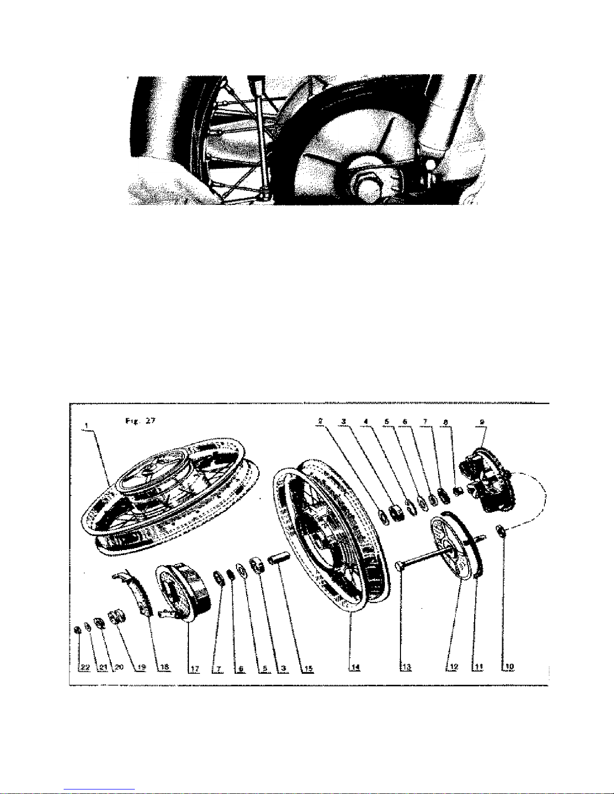
2. REMOVING THE REAR WHEEL
Release the rear brake cable, unscrew the spindle nut, remove the spring washer
and pull out the spindle to the right hand side. Remove the brake reaction bracket
on the L.H. side, slide the wheel off the rubber blocks (coupling of the chain wheel)
and inclining the motorcycle to one side remove the wheel.
To assemble the wheel reverse the above process. The brake-cable should be
adjusted so as to allow free rotation of the wheel.
Fig. 27. Rear wheel brake drum - exploded view

45
3. REMOVING THE CHAINCASE AND THE CHAIN
To make the dismantling of the chaincase easier remove the rear wheel and the
R. H. crankcase cover. Disconnect both chaincase halves and open the chaincase
(Warning! - First remove the split pin from the screw.) Rotate the chain so that
the connecting link reaches the rear chainwheel release the clip and remove the
connecting link using pliers or a screwdriver. Pull out the chain and take in turn
the chain-case halves out rearwards.
When replacing the chain proceed as follows: slip the disconnected chain on the
gearbox sprocket and fit a piece of wire to the end finks of the chain. Using the
wire pull the chain through the rubber guide in the bottom chaincase half placed
in position. Slip the chain on the rear chainwheel and fasten with wire to prevent
it from falling into the chaincase. Using the wire pull the other end of the chain
through the rubber guide in the chaincase top half placed in position. Slip the top
end of the chain over the rear chainwheel and connect the two chainends with
the connecting link and clip. The open end of the spring clip should face the
opposite direction of the chain rotation. Insert the rubber seal between the top
and bottom halves of the chaincase, fasten the halves together by means of the
bolt and nut and seem with the split pin.
When replacing the chain it is not necessary to dismantle the chaincase. Connect
the new chain to the old one and with its help pull the new chain to its operational
position.
4. REMOVING THE REAR CHAINWHEEL
This operation can be carried out after the rear wheel and the chaincase have
been removed, Slacken the chainwheel nut (32) and remove the chainwheel
together with the back plate,
5. REPLACING THE WHEEL BALL BEARINGS
Remove the brake drum back plate with the brake shoes. Remove the seals from
both sides of the wheel hub and on the side

46
of the splines driver remove the bearing circlip. From the opposite side push the
other bearing using a piece of tube until the unlocked bearings fall out. Push the
remaining bearing out to the opposite side and remove the spacer. Warning!
Before removing the front wheel bearings the hub cover (of the splined driver)
should be removed first. Press in the new bearings by applying pressure to the
outer bearing race, using a piece of tube. When replacing the rear chainwheel
bearings proceed as follows : Remove the back plate and push out the spacer.
Remove the seal, bearing circlip and bearing from the L. H. side using a piece of
tube. Press on the new bearing using again preferably a piece of tube of a diameter
corresponding to the bearing outer race diameter.

47
Fig.28. Rear wheel - sectional view

48
Fig.29. Front wheel - sectional view

49
6. REMOVING THE CYLINDER HEAD AND BARREL
Disconnect the fuel pipe (from the carburetter to the fuel tank) and remove the
Dual Seat and the fuel tank (for dismantling instructions refer to para 13 & 14).
Disconnect the Ignition coil and sparking plug leads and remove the H. T. Ignition
coil. Disconnect the exhaust pipe, unscrew the four nuts holding the cylinder
head to the cylinder barrel and remove the cylinder head. By means of the
kickstarter bring the pistons into the B.D.C, position and push the cylinder barrel
upwards.
Note: If it is difficult to remove the cylinder head lever it carefully by placing a
screwdriver between the cylinder head and cylinder fin at the spot where the fins
join. After dismantling cover up the crankcase opening to prevent dirt entering,
Fig. 30 Disconnecting the exhaust pipes Fig. 31 Removing the cylinder head

50
7. REPLACING THE PISTON RINGS
The piston rings have to be replaced should the gap exceed 0.8 mm (0.031 in.),
the correct gap being 0.2 mm (0.008 in.). To check the gap width insert the
removed piston ring into the cylinder top part (approx. 10 mm. (0.39 in.) deep),
and check gap by means of a feeler gauge. The best way to remove the position
rings is to use three thin steel strips. Insert one strip under the piston ring in the
middle and the two others under the piston ring ends. To replace the piston rings
proceed in the same manner.
8. REMOVING THE CARBURETER
a) Disconnect the fuel pipe where it joins the fuel tank.
b) Loosen the carburetter cover unscrewing the fastening nut off the mixing
chamber.
c) Remove the cover and slacken the flange fastening nuts.
d) Push the carburetter out rearwards,
e) When removing the carburetter leave the induction Silencer in its place
disconnecting only the rubber sleeve.
Fig. 12 Removing the cylinder barrel

51
9. DISMANTLING THE CLUTCH
After removing the L. H. crankcase cover the clutch can be dismantled.
Preferably use the double end ed spa nner (10) to press in the cups which
hold the lock pins. Press in the cups one after other and remove the pins in
the same order (three times). The clutch has five plates with cork inserts and
four metal plates (plus one pressure plate). When reassembling insert first the
plate with a cork insert which was under the pressure plate.
10. DISMANTLING THE HEADLAMP
The headlamp consists of three main parts : rim with reflector, bottom and top
nacelle.
Remove the rim with reflector after unscrewing the securing screw M 5 from
the rim bottom, swing the rim upwards and disconnect the joint with leads.
Fig. 33 Fitting the piston rings

52

53
Remove the top nacelle after releasing the catches inside the na celle
and unscre wing the speedome ter drive union n ut.
Remove the bottom nacelle after removing the handlebars (see pars
12), disconnecting the leads and the clutch cable, unscrewin g th e
st ee rin g hea d nut (4 1) an d u ns cr ewi ng th e pl ug screws (32).
Remove now the fork head lug and the bottom nacelle can be pushed
out.
II. DISMANTLING THE STEERING HEAD AND FORK LEGS
Remove first th e top nace lle, hand lebar s, unsc rew the nuts (41) and
(32) and release the fork head lug by tapping. By using a special box
spanner partly unscrew the nut holding the be aring cup. In this manner it
is possible to lubricate the top.
Fig. 35 Lubricating the steering head Fig. 36 Lubricatin g the steer ing head

54
bearing balls. Push the steering head column downwards and then the bottom
bearing can be lubricated. When completely dismantling the fork unscrew the nut
fully; unscrew the valves from the fork tube top portion; slacken and remove the
steering lug and stem pinch bolts, and push out one after the other the fork legs
and the steering head column,
To remove the front suspension dampers from fork legs, unscrew the drain
plug '14' (Ref. Fig. 34) and top nut '1' (after removal of top nacelle) and pull
out the entire damper unit from top of the fork tube '3'.
When refitting the damper unit into the fork tube ensure that the pin at
the bottom of the end-tube '15* is located correctly into the locating hole in
the slider bottom '12'. as otherwise the front suspension will become
inoperative.
Fig. 37 Adjusting the twist grip

55
The handlebars are fastened by two clamps locked by four screws and two nuts
M 8. Four spring washer complete the set The handlebars can be removed after
easing the headlamp rim with reflector and after removing the top nacelle (para 10),
and slackening the clamp locking screws. The twist grip can be pulled off after
unscrewing the countersunk head screw through the opening in the rubber grip and
plug. The twist grip rotation can be adjusted by the screw in the retention cap.
14,. REMOVING THE DUAL SEAT
Slacken the screw M 6 through the opening in the cowl on the L. H. side. Lift the
front of the dual seat and by pulling it forwards and upwards remove it.
Underneath the dual seat the induction silencer, rectifier as well as an auxiliary tool
box are located.
15. REMOVING THE FUEL TANK
Disconnect the fuel pipe and unscrew two screws M 8 x 10 securing the front clamp
ears and the through bolt with nut (14/12) securing the rear clamp ears.
Do not forget to replace the three spring washers when reassembling.
16. REMOVING THE TOOL AND. BATUM' BOXES AND COWLS
The tool and battery boxes and cowls are held by three screws to the frame of the
machine. Before dismantling do not omit to remove from the R. H. box the stop
switch.
Unscrew the following parts from the It H. side; nut (12) and through bolt
(14) securing the filet tank rear clamp ears, the bolt (10) securing the rear
wheel brake control cable clamp and bolt (10) and nut near the pillion footrest.
From the L. H. side unscrew : the front footrest bolt (12) as well, as the bolt
(10) and nut near the pillion footrest.
Now unscrew the remaining screws securing the cowls and remove the cowls.

56
16. DISMANTLING THE REAR SUSPENSION
Having unscrewed two screws M 8 remove the suspension unit
from
its brackets
in the frame and pivoted rear fork. As compared to the former the new type damper
has increased damping efficiency and is so designed that no topping up with oil is
required.
It is recommended to have any possible repairs, cleaning the interior etc., done in a
specialist workshop.

57
Fig. 40 Pivoted rear fork bushing - sectional view
1. Pivoted rear fork 7. Fork pin
2. Bush 8. Nut
3. Rubber seal 9. Locking bolt with nut Lubricating Pipe
4. Bolt 11. Screw M8X55
5 Thrust washer
6. Cup
17. PIVOTED REAR FORK
Before removing the pivoted rear fork the following operations have to be carried
out:
Remove the cowls (para 15), the suspension dampers (para 16), The rear wheel
(pars 2), chaincase (para 3) and the rear chain (para 4),. and exhaust silencers.
After removing these parts unscrew the bolt and nut on the tube bottom and the
two nuts (17) on the L. H. side of the frame. Push the released bolt out to the R.
H. side and remove the thrust washer. Using a puller pull out the fork pin. It is
recommended to have this repair done in a specialist workshop equipped with
special tools.

58
8. REMOVING THE BATTERY
Open the L. H. side box and remove the fuse case from its holder thus
disconnecting one lead and disconnect the order lead (earthing + pole) by
unscrewing the nut (10) and pushing the washer off the earthing screw. Pull down
the securing strap and remove the battery.
Fig. 41 Removing the battery
19. DISMANTLING THE SWITCH BOX
Dismantle the switch box only if absolutely necessary. Free and lift the headlamp
reflector and remove the speedometer head. After freeing the headlamp top
nacelle, the switch box located in it becomes accessible.

59
20. REMOVING THE ENGINE FROM FRAME
Disconnect : 1. the fuel pipe, 2. throttle and clutch cables (in the engine), 3. the
speedometer drive (the screw in the bottom part of the L. H. half of the crankcase),
4. the sparking plug lead and 5. the exhaust pipes
Remove : 1. the dual seat, 2. the chaincase, 3. the L. H. battery box, 4. the R. H.
engine cover, 5. the chaincase extension, and 6. disconnect the leads from the
mag-dynamo terminal base.
Having removed the dual cowl bottom the rear engine bolts have become
accessible; slacken the bolts and remove them. Then slacken and remove four
front bolts fastening engine to frame and remove the engine to the L. H. side.
21. REMOVING THE R. H. AND L. H. ENGINE COVERS
Remove the R. H. Cover when clutch adjustment (for thorough adjustment see
Part II, pars 6) or ignition setting is required. Unscrew the two screws and remove
the cover.
Before fitting the cover clean the seating faces off mud. Tighten the securing
screws evenly and check the cover front part to seat down properly (in order to
prevent the water leaking into the magneto space).
Remove the L. H. cover when it is necessary to dismantle the clutch to replace the
clutch plates) or the primary chain. Proceed as follows 1. drain the oil, 2. slacken
the 5 securing screws, 3. remove the cover along with the gear lever and shaft by
carefully levering with two screwdrivers placed in the openings in the front and
rear part of the cover.
When refitting the L H. side cover do not forget to insert a new paper gasket and
to tighten properly the screws in order to prevent oil leaking around the cover and
the crankcase seating faces.
Note:
The right is reserved to effect modifications caused by development in the
illustrations or specifications in this Manual.
IDEAL JAWA - Mysore, India

60
IV. DEFECTS, CAUSES AND REMEDIES
Trouble Location Remedy
Lumpy Running
Engine Knocks
Engine overheated.
Plug points glow, faulty
sparking plug.
Cylinder head clogged with
carbon.
Over-advanced ignition.
Exhaust silencer clogged.
Wait until engine has cooled do not run
at high revolutions.
Replace sparking plug.
Remove cylinder head and decarbonise.
Adjust correct gap and reset ignition
timing.
Detach exhaust silencer and clean it.
Engine misfires
Regular sparking
Water or oil in carburetter.
Insufficient fuel supply.
Temporary short circuiting
caused by faulty plug lead.
Weak mixture.
Improperly mixed petroil.
Clean the carburetter.
Open reserve supply tap. pass fuel
over, re-fuel, inspect inlet manifolds.
Tape crack in insulation or replace
lead.
Adjust carburetter.
Stir mixture properly before re-fuelling.
Irregular sparking
Unsuitable sparking plug.
Oiled sparking plug.
Excessive spark gap.
Dirty breaker points.
Improperly adjusted breaker
points.
Temporary short circuiting
caused by faulty plug lead.
Replace sparking plug.
Remove and clean sparking plug.
Adjust correct spacing to 0.45 mm
(0.018 in).
Clean the points using a cloth soaked
in petrol.
Adjust to 0.4 mm.
Tape crack in insulation or replace
lead.

61
Trouble
Location
Remedy
Engine will not fire, or has
stopped. Carburetter can be flooded
Compression regular
Sparking Regular
Carburetter in order
Engine overheated.
Insufficient Lubrication
Throttle cable broken.
Air leak between
carburetter and cylinder.
Let the engine cool and keep
it at low revolutions.
Take care that petroil is
mixed properly at ratio 20 to
1 (16:1 during running-in).
Replace throttle cable.
Replace gasket.
Carburetter
faulty
Jet chocked.
Leaking float.
Float stuck.
Float needle does not set
properly.
Remove and clean the jet.
Solder or replace the float.
Release the float.
Repair or replace the needle.
Lumpy running
Engine lacks power
Permanent
Carbon accumulation in
cylinder barrel and head,
exhaust passages and
silencers.
Insufficient fuel feed.
Improperly set ignition.
Improper carburetter
setting (improper mixture).
Exhaust silencers clogged.
Worn cylinder interior and
piston.
Engine drags wrong air
(crankcase halves or
carburetter stump are not
tight)
Remove cylinder head and
barrel, exhaust pipes and
decarbonise.
Dismantle and clean fuel
pipe.
Adjust breaker point gap and
ignition advance.
Adjust idling peed, needle
position and clean air
cleaner.
Dismantle and decarbonise.
Rebore cylinder, replace
piston and rings, have
gudgeon pin bearing checked
(at an accredited workshop)
Take both cranckcase halves
apart, clean joint faces.
Apply jointing compound
and reassemble properly.
Replace carburetter stump
gasket.
Temporary
Fuel pipe or cleaner partly
clogged.
Throttle control cable sticks
Engine overheated.
Faulty sparking plug.
Clean fuel pipe or cleaner.
Lubricate or replace.
Allow the engine to cool and
keep it at low revolutions.
Replace the sparking plug.

62
Trouble
Location
Remedy
Engine will not fire – Engine has stopped
Carburetter cannot be
flooded
Empty fuel tank.
Fuel tap off.
Fuel filter above the-tap
clogged.
Chocked fuel pipe or screen in
carburetter.
Clogged filler cap vent on the
fuel tank.
Transfer fuel reserve and refuel at the earliest convenience.
Turn fuel tap on.
Unscrew the fuel tap and clean
the filter.
Remove and blow the fuel
pipe, remove and clean the
carburetter.
Clean filler cap vent.
Carburetter can be flooded
Irregular sparking
Spark at lead end
Oiled sparking plug.
Damaged plug insulation.
Short circuiting between
sparking plug points.
Plug points gap too wide.
Remove and clean sparking
plug.
Replace plug.
Clean sparking plug.
Adjust sparking plug gap to
0.45 mm. (0.018 in.)
No spark at lead end
Ignition key not inserted.
Insert the key.
Dirty breaker points.
Faulty breaker points.
H. T. lead broken or loosed.
Burnt lead insulation.
Faulty condenser. .
Damaged stator winding
insulation.
Water in contact breaker.
Clean the point using a cloth
soaked in petrol.
Have point replaced.
Tape insulation crack,
replace lead at the earliest
convenience.
Tape lead and replace at the
earliest convenience.
Replace condenser.
Refer to a specialist workshop.
Blow out water. wipe off
carefully, allow to dry.
Regular sparking
Compression poor
Broken piston ring.
Jammed piston ring.
Sparking plug washer leaks.
Replace ring.
Remove, clean and replace
ring.
Replace washer.

63
TWO-STROKE ENGINE OPERATION
The two-stroke petrol engine is particularly suitable for motorcycles, having few
moving parts it is subjected to less wear and consequently is more reliable in
operation, its working action is accomplished in a single crankshaft revolution
(i.e. two piston strokes).
1. PISTON MOVES UPWARDS
The piston closes first the transfer ports, then the exhaust port and causes
compression of the mixture in the compression space of the cylinder head. A few
moments before the piston reaches its T.D.C. position the compressed mixture be
ignited by the electric spark from the sparking plug.
In the meantime a vacuum (underpressure) is created underneath the piston,
causing induction of fresh mixture from the carburetter to in the interior of the
crankcase.
2. PISTON MOVES DOWNWARDS
After ignition of the mixture the actual working stroke of the piston begins
(transmitting the power of the expanding gases by means of the crankshaft
mechanism and transmission to the motorcycle rear wheel). The top edge of the
piston opens first the exhaust port and the exhaust of the burnt gases takes place.
The top edge of the piston then opens the two transfer ports. Under the piston
and in the interior of the crankcase is fresh mixture, compressed by the piston
during its downward stroke. Through open transfer ports this fresh mixture will
now flow into the cylinder directed by the shape of the ports: the two streams
meet, reach the opposite cylinder wall, proceed towards the cylinder head which
directs them to the exhaust ports side. The fresh mixture fills the cylinder,
pressing at the same time the remaining burnt mixture out (scavenging).
64
Fig. 42 Two-stroke engine operation diagram

65
Printed by: PRINTOKRAFT, Bombay – 400 057 at The Book Centre Ltd.
Sion East, Bombay – 400 0022 20000-7/77
 Loading...