

Page 1

X-Media DreamBox
X-Media 5.1 DreamBox
View High Resolution TV/Video on PC monitor
Package Included:
þ X-Media DreamBox
þ Infra Remote Control
þ 2 x ‘AAA’ size Batteries
þ 5’ VGA Extended Cable
þ 5’ Audio Extended Cable
Page 2

Thank you for purchasing the X-media DreamBox / X-Media5.1
DreamBox (Model 5.1)!
With this X-media DreamBox or Model 5.1, you can turn your RGB
monitor or LCD display panel into a TV with or without even having
to turn on your computer. Just plug it into your monitor or LCD
display and you’re ready to watch TV, DVD, RCA programs, or
play video games. X-media DreamBox, or Model 5.1 is completely
plug-n-play. This is no software driver required.
CAUTION
You are cautioned that any changes or modifications not
expressly approved in this manual could void your authority to
operate this equipment.
If not installed and used in accordance with the instructions, this
equipment may causes corrupt interference to radio
communications. However, there is no guarantee that interference
will not occur in a particular installation. If this equipment does
cause equivocal interference to radio or telephone reception, which
can be determined by turning the equipment off and on, the user is
encouraged to try to correct the interference by one or more of the
following measures:
− Reorient or relocate the TV antenna if there is any.
− Increase the separation between the equipment and
Telephone reception.
− Connect the equipment into an outlet on a circuit different from
that to which the radio receiver is connected.
− Consult the dealer or an experienced radio/Telephone
technician for help.
About operating voltage
Operate the unit with the appropriated on the outer packaging and
Page 3

About installation
Do not place the unit near heat sources, rain, moisture or
mechanical shock, and ensure that there is nothing to interfere
with proper ventilation/airflow.
IMPORTANT SAFETY INSTRUCTION
1. Read these instructions.
2. Keep these instructions.
3. Heed all warnings.
4. Follow all instructions.
5. Do not use this apparatus near water.
6. Clean only with a damp cloth.
7. Do not block any of the ventilation openings. Install in
accordance with the manufacturer’s instructions.
8. Do not install near any heat sources such as radiators, heat
registers, stoves, or other apparatus (including amplifiers) that
produce heat.
9. Protect the power cord from being walked on or pinched
particularly at plug, convenience receptacles, and the point
where they exit from the apparatus.
10. Only use attachments/accessories specified by the
manufacturer.
11. Refer all servicing to qualified service personnel. Servicing is
required when the apparatus has been damaged in any way,
such as power-supply cord or plug is damaged, liquid has
been spilled or objects have fallen into the apparatus, the
apparatus has been exposed to rain or moisture, does not
operate normally, or has been dropped.
WARNING: To reduce the risk of fire or electric shock, do not
expose this apparatus to rain or moisture.
Page 4

WELCOME!.........................................................................................................2
CAUTION...........................................................................................................2
ABOUT OPERATING VOLTAGE .......................................................................2
ABOUT INSTALLATION...................................................................................3
IMPORTANT SAFETY INSTRUCTION.....................................................3
FEATURES:......................................................................................................6
SPECIFICATION.............................................................................................7
BOX UNIT [F]...................................................................................................8
BOX UNIT [R]..................................................................................................9
BASIC CONNECTION.................................................................................11
OPTIONAL CONNECTION........................................................................12
REMOTE CONTROL...................................................................................17
OSD MENU.....................................................................................................18
V IDEO 1.............................................................................................................18
V IDEO 2.............................................................................................................18
AUDIO ...............................................................................................................20
CLOCK...............................................................................................................21
SETUP ...............................................................................................................22
SVGA.................................................................................................................23
TV......................................................................................................................24
PANEL CONTROL.......................................................................................25
TROUBLESHOOTING .................................................................................25
Page 5

LIMITED NINETY (90) DAY WARRANTY....................................................32
LIMITED ONE (1) Y EAR WARRANTY...........................................................32
RENTAL UNITS................................................................................................33
COMMERCIAL UNITS......................................................................................33
REGISTER PRODUCT .......................................................................................33
Y OUR RESPONSIBILITY..................................................................................33
IMPORTANT: PACKING AND SHIPPING INSTRUCTION................35
Page 6

• Watch TV or Video without Turning on your computer
video games for your computer.
• Compatible with all VGA, LCD, and Mac monitors
• Plug-n-Play! No software drivers required
• Play your favorite games with consoles like Nintendo, Sega
, Dreamcast and Play Station 2, X-Box, etc.
• Full screen, or size-selectable windows display on monitor
• Easily switch to TV, Video or PC display
• Full functional infrared Remote Control
• Built-in Touch Button Control Panel
• Auto-scan, to memorized all active TV channels line up in
your area
• Support 125 Channels
• On-Screen Display (OSD) Menu
• Sleep/Alarm/Timer Setup function
• Brightness/Contrast/Hue/Color/Saturation adjustment
• Available interpretation in NTSC or PAL
• Supports 640x480@60Hz, 640x480@72Hz, 800x600@60Hz,
1024x768@60Hz resolution and refresh rate for video output
Imagine turning your regular PC into the best multimedia
entertainment system! X-media DreamBox uses the latest DeInterlacing method, which delivers superior image and picture quality.
X-media DreamBox not only allows you to watch TV or video, but also
comes with input connectors to hook up with a VCR for playing video
tape. In addition, the AV, S-Video and RCA input allow you to connect
with a Nintendo, Sega, Dreamcast or Play Station 2 for the exciting
Page 7

during your most busies working hour. Other unique features
including support up to 1024x768 display resolution, multi-lingual onscreen display (OSD), sleep timer functions, and more.
Box unit, and Remote Control
Your Package may also contain other printed material with special
offers for direct purchase of related products as well.
Specification
Physical Dimension: Width = 8 ¬”, Height = 2 ¬”, Depth
= 6” (Box only)
TV Program Source: n TV Antenna (75Ω)
n Cable TV (Coaxial)
Input Video Source: n Video Camcorder
Page 8

Input Audio Source: - PC Sound Card
• Power - Turn the unit on / off
Video Output: VGA out (DB 15)
- Output:
• RGB Monitor
• Analog LCD Monitor
AC Adapter (Model 5.1): AC-120V, 60Hz / DC - 12V 1A
(Class 2 Transformer)
AC Adapter: AC-120V, 60Hz / DC - 12V 1.2A
(Class 2 Transformer)
Audio Output: - Speakers (with Amplifier built-in)
(Not included)
Video Signaling: NTSC / PAL
NTSC (Default setting)
TV Signaling: NTSC (Model # 91007N)
PAL (Model # 91007P)
Note: All dimensions are Inches, otherwise may specified.
Feature and specification are subject to change without notices.
Box Unit [F]
Front Side
The touch button panel on the front side of the Xmedia DreamBox provides quick access to
commonly used functions.
Page 9
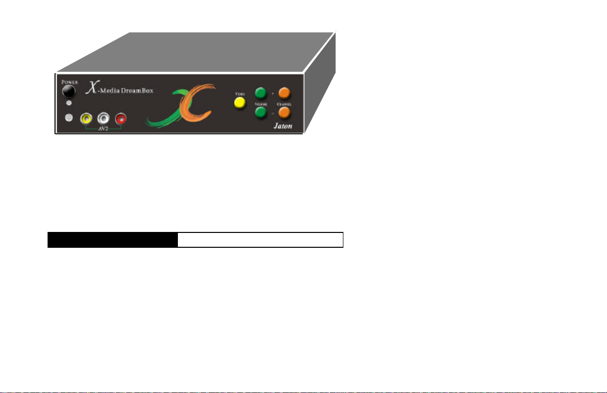
• Volume - Audio level Adjustment
• Channel - TV / CATV channel switch
If your remote control doesn’t function at all, then these buttons on
Box front panel will acting as a keypad for your screen menu, see
the details on chapter <Panel Control> in this document.
Box Unit [R]
Rear Side
All ports allow you to connect differential sources
IN/OUT for the TV / Video programs, then turnover
VGA Out to your monitor (s). (describe from left to
right on bottom raw)
• DC Plug - DC power from the AC Adapter.
• Audio In - Audio source from PC sound card (Optional
Connection).
• Audio Out - Audio output to speaker (s).
• VGA In - Port for PC video from your computer
(Optional Connection).
• VGA Out - Port for all videos out to your monitor (s).
Page 10
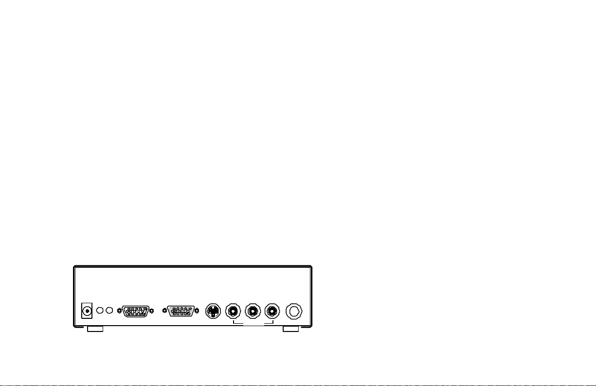
Red for right channel on audio (Optional connection).
• AV1_L - Analog Video Composite Input in colored
White for left channel audio (Optional connection).
• AV1_Video - Analog Video Composite Input in colored
Yellow for video signal (Optional connection).
• TV ANT / CABLE - port for TV Antenna or CABLE TV
(CATV) signal input.
Optional Features on Model 5.1 (describe from left to right
on top raw)
• G9 CS 5.1out - An Audio out from G9Pin connector to
CS 5.1 channel speaker system or decoder.
• Audio Switch - Switching Audio modes between
Cinema and Movie.
• COMPONENT VIDEO - Analog Video Component
input from Component Video equipment such as DVD
player component video-out, Video Conference
controller.
(If you have loss signal on UHF/VHF/FM, you may use
signal amplifier to boost receiving “F” type signal in clear
levels. Signal amplifier is sold separately, and it is
available in most TV/Radio stores.)
IN OUT
DC 12V/1A Audio VGA IN VGA OUT S_Video TV ANT / CABLE
R L Video
AV1
Rear Side Diagram.
Page 11
IN OUT
G9
Movie
COMPONENT VIDEO-IN
R L Video
DC 12V/1A Audio VGA IN VGA OUT S_Video TV ANT / CABLE
AV1
Model 5.1 Rear Side Diagram.
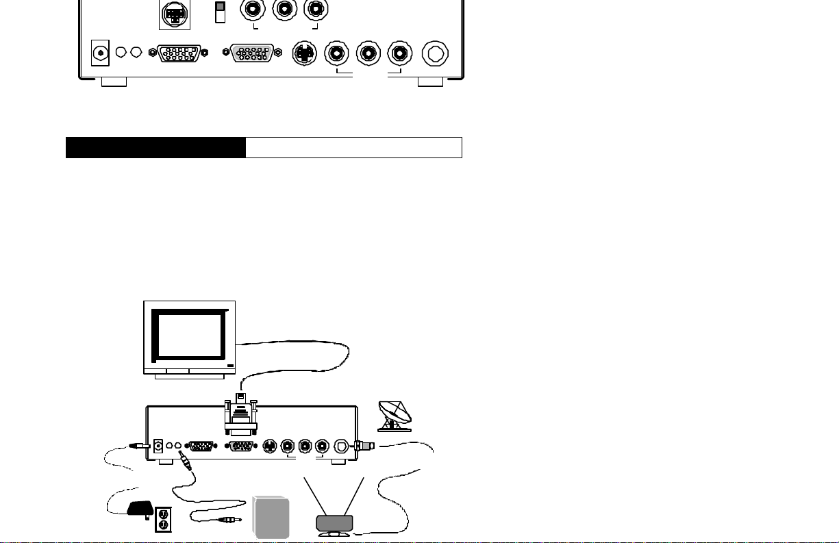
Basic Connection
Unit
The basic connection only plug your monitor to the VGA out port,
plug Audio out to your speaker(s) and then connect AC / DC
adapter from AC outlet to DC port on this unit. Either TV Antenna
or Cable TV connector should plugged to the unit before you turn
the power on.
Monitor
IN OUT
DC 12V/1A Audio VGA IN VGA OUT S_Video TV ANT / CABLE
~
~
R L Video
AV1
CABLE TV
~
~
AC Outlet
Page 12

a single display for your TV or CATV program. Both RGB and LCD
can display in full screen.
FRONT
RIGHT
CENTE
R
FRONT
LEFT
SURROUND
RIGHT
I
IN OUT
DC 12V/1A Audio VGA IN VGA OUT S_Video TV ANT / CABLE
AC Outlet
SURROND
LEFT
SoundMax 5.1
!
CS 5.1 out Cinema
G9
Music
Y Cr Cb
COMPONENT VIDEO -IN
Surround
R L Video
AV1
Jaton DVD Player
Center
Stereo
L
RLR
CABLE TV
Optical
Y Cr Cb
Video
S-Video
Out
SPDIF
Monitor
There is no different on the basic connection between the two
models, simply TV-to-Monitor, but the model 5.1 added more
optional connections for features on leading technology.
Optional Connection
Unit
Certainly, you can plugged all kinds differential I/O into this unit to
performing more video / audio action accomplishment than just
watch TV on your monitor. In advanced connections, all ports on
front and rear sides are optional and available for your game
console, camcorder, DVD video player, also you can
simultaneously working with your computer and have another video
Page 13

CRT monitor
Analog LCD Display
POWER
VOLUME
VOLUME
-MIC-
DVD Player
OPEN / CLOSE
STOP
F.F.REW.
PAUSE
PS 2
All video sources you can connect to
Your PC
Optional Connection
IN OUT
DC 12V/1A Audio VGA IN VGA OUT S_Video TV ANT / CABLE
S_Video or RCA ports.
Optional Connection
R L Video
VCR
Video Camcorder
AV1
Optional connection as shown as above, which gives you more
ideas to add more video sources to this unit, and there is no doubt
about this unit capable of handling all of those functions as well.
This is a Plug-n-Play unit without any software not even the
Microsoft windows.
Page 14

Receiver with 5.1 ch. Input
DVD Player Component Video-out
Video Conference Equipment
The Component Video Input at rear side will share the VIDEO of
AV2 port in same implement circuitry, that means you only can
plug-in each port on one time. Accurately the same procedure on
Movie
Y Cr Cb
COMPONENT VIDEO-IN
R L Video
AV1
POWER
VOLUME
VOLUME
-MIC-
DVD Player
VCR
CS 5.1 out Cinema
IN OUT
DC 12V/1A Audio VGA IN VGA OUT S_Video TV ANT / CABLE
G9
Video Camcorder
Your PC
PS 2
OPEN / CLOSE
STOP
F.F.REW.
PAUSE
Page 15

PC - VGA out
Your PC
PC - Speaker out
SOUND CARD
JP2 1
R G G L
JP8 JP7
AMP
CD-IN
G L G RJP3
Video AUX PHONE
R
G
G
MON
O
L
JP9 JP10 JP11
PC SPK
JP1
S_Video out / Video out from these video sources
POWER
VOLUME
VOLUME
-MIC-
Connection Diagram - 1.
PC - VGA out
Your PC
R G L G
VIDEO AUX TAD
TAD 1
PC SPK
J
P
1
L G G R
VIDEO 1
PANASONIC 1
SONY 1
AUX 1
1
GAME 1
Multiple Channel Sound Card
Monitor
IN OUT
DC 12V/1A Audio VGA IN VGA OUT S_Video TV ANT / CABLE
STOP
F.F.REW.
PAUSE
DVD Player
OPEN / CLOSE
PS 2
R L Video
AV1
VCR
Video Camcorder
Line In
IN OUT
DC 12V/1A Audio VGA IN VGA OUT S_Video TV ANT / CABLE
R L Video
AV1
Monitor
(Surround Sound System
with Mixer Subwoofer)
S_Video out / Video out from these video sources
STOP
Page 16

The first connection it described above, the audio out is straight
from the source to speaker even without turn on your PC, there are
two channels in stereo.
If your connection as second diagram illustrated above for
surround sound output, then your PC must be turned on to
keeping the multiple channels sound card activate for operation.
AV2 ports at front side on this unit are the optional connections for
you playing video programs on tap from VCR/Camcorder to your
PC monitor, also adapted for Game console input.
Composite Video Out From These Video Sources
VCR
Camcorder
• Colored Red Jack - Audio right channel.
• Colored White Jack - Audio left channel.
• Colored Yellow Jack - Video channel.
PS 2
Game Console
Page 17

PC: Switch between PC
and last Video CH
VIDEO: Main Video
CH select
MENU: OSD Setup
RETURN: Menu select
LEFT: '<-' or '-'
DISPLAY: CC on
/ Show status
DOWN: OSD
cursor down
0-9: TV CH input
JUMP: Back to
last CH
ALARM: ON /OFF
SLEEP: Sleep (0, 15,
30, 60, 90, 120 Min.)
AUDIO: Audio CH select
SIZE: Change PIP size
(1/4, 1/3, 1/2, Manual)
Alarm
MENU
RETURN
DOWN
DISPLAY
1 2 3
4 5 6
7 8 9
JUMP
0
Jaton
UP
MUTEPCVIDEO
ENTER
MTS/SAPALARMSLEEP
POWER
PIP ADJUST
HELP
+
CH
+
VOL
PIP
SELPOSSIZEAUDIO
-
-
POWER: Video power
MUTE: Muting
PIP ADJUST: Manul adjust
PIP size and position
UP: OSD cursor up
RIGHT: '->' or '+'
HELP: Remote control online help
CH +: Next channel
CH -: Last channel
VOL +: Volume increase
VOL -: Volume decrease
ENTER: Enter TV CH
PIP: PIP ON / OFF
MTS/SAP: SAP/steror/Mono
SEL: PIP input video select
POS: Change PIP position
(Right bottom/left bottom/
Left top/Right top/Manual)
Definition:
OSD On Screen Display (screen menu)
PIP Picture-In-PC (Video overlay top on your PC video)
CH Channel of Audio / Video
POS Position
SEL Select
Page 18

Before you ready to setup OSD menu, make sure you have powerup this unit and other devices you wish to use with. Of course,
your monitor must be turn on.
Press “Menu” key: use “up” & “down” for pull-down-list items
selected, “left” and “right” key will loop on top bar menu selecting
from left to right, all items selecting by highlight in blue color.
Video 1
< Top Bar Menu >
VIDEO 1 2 AUDIO CLOCK SETUP
Video Color / Display Setting
RED
GREEN
< PULL DOWN LIST >
BLUE
BRIGHTNESS
CONTRAST
SATURATION
HUE
SVGA TV
press on
left or
right key
to adjust
value, or
turn ON/
OFF on
specific
function
in each
pull down
item.
->, <- up, down: Select / Adjust Menu: Exit
The remote control must be pointing to the unit box, not to your
monitor if they were in separate places.
Page 19

VIDEO 1
2
AUDIO
C
LOCK
SETUP
Advanced Video Setting
SVGA
TV
Y / C
DTFNR
< PULL DOWN LIST >
GAMMA
DCTI
DLTI
MDETECT
ASPEC RATIO
SIGNAL TYPE
0 - 7 (0 - Default)
LOW / MID / HIGH / OFF (LOW - Default)
ON / OFF
ON / OFF
ON / OFF
ON / OFF
4x3 / 16x9 (4x3 - Default)
NTSC / PAL (NTSC - Default)
press on
left or
right key
to adjust
value, or
turn ON/
OFF on
specific
function
in each
pull down
item.
->, <- up, down: Select / Adjust Menu: Exit
• Y/C - V-size / Center screen Adjustment
• DTFNR - Dynamic Temporal frame-Filtering Noise Reduction
• DCTI - Dynamic Chrominance Transience Improvement
• DLTI - Dynamic Luminance Transience Improvement
• MDETECT - Motion Detection
Page 20

VIDEO 1 2 AUDIO CLOCK SETUP
Audio Setting
VOLUME
BASS
< PULL DOWN LIST >
TREBLE
LOUDNESS
MUTE
ON / OFF (OFF - Default)
SVGA TV
->, <- up, down: Select / Adjust Menu: Exit
< Top Bar Menu >
press on
left or
right key
to adjust
value, or
turn ON/
OFF on
specific
function
in each
pull down
item.
Page 21

VIDEO 1 2 AUDIO CLOCK SETUP
Clock / Alarm Setting
SLEEP MODE
SET TIME
< PULL DOWN LIST >
SET ALARM
ALARM SOURCE
ALARM TIMER
OFF / 15 Min. / 30 Min. / 60 Min. / 90 Min. / 120 Min.
00:00 ( Selectable on AM or PM)
00:00 ( Selectable on AM or PM)
1 - 125 ( Number of your TV or CATV Channel)
ON / 10 Min. / 30 Min. / 60 Min. / OFF
SVGA TV
->, <- up, down: Select / Adjust Menu: Exit
< Top Bar Menu >
press on
left or
right key
to adjust
value, or
turn ON/
OFF on
specific
function
in each
pull down
item.
Page 22

VIDEO 1 2 AUDIO CLOCK SETUP
< Top Bar Menu >
SVGA TV
OSD Language and Reset to Default
LANGUAGE
SET CC
< PULL DOWN LIST >
OUTPUT MODE
VIDEO SETTING
AUDIO SETTING
VIDEO 2 INPUT COMPOSITE / COMPONENT (Composite is default)
->, <- up, down: Select / Adjust Menu: Exit
ENGLISH / CHINESE
CC OFF / CC 1 / CC 2 / CC 3 / CC 4
640x480x60Hz / 640x480x72Hz / 800x600x60Hz /
1024x768x60Hz
RESET > (OK) (Press " Menu" back to default)
RESET > (OK) (Press "Menu" back to default)
This selectable option is only shown on the Model 5.1
press on
left or
right key
to adjust
value, or
turn ON/
OFF on
specific
function
in each
pull down
item.
• CC - Closed Caption
• CC 1 - Caption in 1st position
• CC 2 - Caption in 2nd position, and so on.
• OUTPUT MODE - Full screen display resolution
640x480x60Hz (Default)
640x480x72Hz (Not recommended for TV
mode)
800x600x60Hz
1024x768x60Hz
• VIDEO 2 INPUT - An optional Analog input for
Component/Composite video resource. Default setting is
composite.
Page 23

< Top Bar Menu >
VIDEO 1 2 AUDIO CLOCK SETUP
SVGA / PIP SETTING
PIP FINE PICTURE
PIP BORDER
< PULL DOWN LIST >
PIP SELECT
PIP POSITION
PIP SIZE ADJUST
RESET SETTING
->, <- up, down: Select / Adjust Menu: Exit
0 - FF (Use left & right key to change value)
ON / OFF
TV / AV1 / SVIDEO / AV2
LEFTBOTTOM / RIGHTBOTTOM / LEFTTOP / RIGHTTOP
MEDIUM / SMALL / LARGE
> (OK)
SVGA TV
press on
left or
right key
to adjust
value, or
turn ON/
OFF on
specific
function
in each
pull down
item.
A value of numeric or/and character combination will automatically
shown on your “PIP FINE PICTURE” pull down list (the range from
0 to FF, 165 combinations between). Default value on that
aggregation depends on the type of VGA adapter in your PC, and
type of monitor you have plugged. Adjustment may increasing
(right key) or decreasing (left key) ranges on 5 times either way to
tuning for finest setting with refresh rate and frequency
consumption in that PIP. Usually, the default setting on that
selection makes finest choice.
Recommended Refresh Rate and Resolution for VGA card setting.
Resolution (Pixel) Refresh Rate (Hz)
640 x 480 60, 72, 75
800 x 600 60, 72, 75
Page 24

VIDEO 1 2 AUDIO CLOCK SETUP
ADVANCED TV SETTING
CATV
AUTO PROGRAM
< PULL DOWN LIST >
MTS
CH ADD 3
CH ERASE 3
ON / OFF
OFF > (If this function is on, all TV channels are scanned.)
STEREO / SAP / MONO
> (OK) (You may use 0-9 key to add new TV channel.)
> (OK) (You may use 0-9 key to erase TV channel.)
SVGA TV
->, <- up, down: Select / Adjust Menu: Exit
< Top Bar Menu >
press on
left or
right key
to adjust
value, or
turn ON/
OFF on
specific
function
in each
pull down
item.
Page 25

Panel Control
Front Side Key Map
There is another way to display OSD Menu on your monitor
without the Remote Control (If you temperately loss it, or low on
battery).
POWER:
ON/OFF
VIDEO: AV 1
AV 2
S_VIDEO
Up key
TV
PC
Down key
Right Key
Left key
Both bottom press on
sametime = Menu Key
Turn on your monitor, then press “Power” button on this unit (If
power LED was orange). Use both “Volume” up & down buttons to
brings-up OSD menu to your monitor, if the image screen doesn’t
clear then you may use “Video” button to switch the mode you are
expecting so.
TROUBLESHOOTING
If power button doesn’t brings the power up to this unit, try to
unplug the AC/DC adapter from AC outlet then plug again, and
make sure that outlet is actives.
TV/Video-Sync positioning may not centering for all differential
type of CRT monitors or Analog LCD display panels from a variety
of the market, manually to make adjustment on V-sync or H-sync
of your screen that will helps you for the best of view.
Page 26

Customer Service at (408) 934-9369
Glossary
Automatic Gain Control (AGC)
AGC is a circuit designed to boost the amplitude of a signal to
provide adequate levels of recording.
Aspect Ratio
The width to height ratio of an image. A 4:3 aspect ratio means
the horizontal side is a third wider than the vertical size. Standard
television ratio is 4:3 (or 1.33:1). Wide-screen DTV and HDTV
aspect ratio is 16:9 (or 1.78:1).
Alpha Blending
This is the way of combing two images by blending together at
factor of alpha. Alpha denotes the blending factor.
Caption
A textural representation of the audio information in a video
program. Captions are usually intended for the hearing impaired,
and therefore include additional text to identify the person
speaking, off screen sounds, etc.
Chroma
The color component of a video signal, independent of the luma.
Definition
Chrominance
The color component (hue and saturation) of light independent of
luminance. Technically, Chrominance refers to the linear
component of video, as opposed to the transformed non-linear
Page 27

modes. Common film aspect ratios are 1.85:1 and 2.35:1.
Sometimes referred to as Theater modes.
Closed Caption
Text caption for video which are not normally visible, as opposed
to open caption, which are a permanent part of the picture. In the
United States, the official NTSC Closed Caption standard requires
that all TVs larger than 13" include circuitry to decode and display
caption information stored on the line 21 of the video signal.
Component Video
A video system containing three separate color component
signals, either Red/Green/Blue (RGB) or Chroma/color differences
(YCbCr, YPbPr, YUV), in analog or digital form.
Composite Video
A analog video signal in which the luma and chroma components
are combined (by frequency multiplexing), along with sync and
burst. Also called CVBS.
Dynamic Luminance Transience Improvement
It is a content adaptive horizontal peaking for the luma signal to
improve the visual quality of TV picture.
Dynamic Chrominance Transience Improvement
Assuming luma and chroma transitions are normally aligned, the
chroma transition are usually degraded due to narrow bandwidth of
chroma information. By monitoring coincident luma transient, a
faster edge is synthesized for the chroma transitions. This edge
then is aligned with the luma edge.
Dynamic Scan Velocity Modulation (DSVM)
DSVM constantly monitoring the edge information of the picture
Page 28

edges in the picture.
Dynamic Digital Comb Filter (DDCF)
The adaptive comb filter is used for high quality Y/C separation for
both PAL and NTSC signals. The adaptive comb filter can improve
luma resolution and reduces cross talk between luma and chroma.
Dynamic Adaptive Static Detect De-interlacing
Improves the clarity and sharpness of the overall picture by
enhances the "non-moving" portions of the picture by doubling the
resolution of those areas. This unique feature is enabled by
utilizing Trident's proprietary technology.
Dynamic Temporal frame-Filtering Noise Reduction
The motion adaptive non-linear Infinite Impulse Response (IIR) filter
is used to reduce the luminance noise. The amount of noise
reduction is controlled by the motion picture which remove the
tailing effect when there is motion in the picture.
Digital Television (DTV)
In general, any system that encodes video and audio in digital
form. In specific, the Digital Television System proposed by the
ATSC or the digital TV standard proposed by the Digital TV Team
founded by Microsoft, Intel and Compaq.
Dynamic Gamma Control
It is the same as Dynamic Brightness/Contrast Adjustment.
Dynamic Black Level eXtender (DBLX)
The DBLX extends gray to black level to improve the contrast of
the TV picture.
Dynamic Brightness/Contrast Adjustment
Page 29

To remove the high frequency noise in TV picture.
Dynamic Frame/Scan Rate Converter
The DPTV can convert input TV signal to any refresh rate. For
example, it can convert from 50Hz PAL timing to 75Hz noninterlaced output or from 50Hz timing to 100Hz interfaced output.
Dynamic White Peak Level Restriction
Dynamically limits white level of image.
Dynamic Skin Color Correction
Depending on picture content, the DPTV will dynamically change
the gain of U and V channels to make colors on picture more vivid.
Dynamic Digital SVGA Overlay
The DPTV can capture SVGA RGB data into frame buffer. It can
be scaled to any size and overlay with TV picture.
Gamma Correction
The characteristics of the displays using phosphors (as well as
some cameras) are non-linear. A small change in voltage when
the voltage level is low, produces a change in output display
brightness. The same small voltage change at high voltage level
will not produce the same magnitude in output brightness. This
effect or the difference between what you should have and what
you actually measured is known as gamma. Gamma correction is
to process RGB signals to compensate for the gamma of display.
High-Definition Television (HDTV)
A video format with a resolution approximately twice that of the
conventional television in both the horizontal and vertical
dimensions, and a picture aspect ratio of 16:9. Used loosely to
refer to the US DTV system.
Page 30

picture from a standard video signal by using techniques such as
frame doubling, line doubling, and digital signal processing.
Interlaced
A video scanning system in which alternating lines are
transmitted, so that half a picture is displayed each time the scan
beam moves down the screen. An interlaced frame is made of two
fields.
Luma
The brightness component of a color video image (also called the
grayscale, monochrome, or black-and-white component). Nonlinear luminance.
Luminance
Loosely, the sum of RGB tristimulus values corresponding to
brightness. May refer to a linear or non-linear signal.
Moving Pictures Expert Group (MPEG)
An international committee that developed the MPEG family of
audio and video compression systems.
On-Screen Display (OSD).
OSD is a means of displaying system status by overlaying the
information over the picture on the viewing screen directly. Users
can choose to implement text-based or Graphical based OSD
Panorama
A video image that uses non-linear distortion to stretch the sides
more and the center less, thus minimizing the apparent distortion.
This feature is found on some wide-screen television.
Picture-Outside-Picture (POP)
Page 31

source in a small window superimposed in a corner of the screen.
Programmable Zoom Viewer
TV picture can be scaled up or down with any factor.
Progressive Scan
A video scanning system that displays all lines of a frame in one
pass. Contrast with interlaced scan.
Standard Definition Television (SDTV)
A term applied to traditional 4:3 television (in digital or analog form)
with a resolution of about 700x480 (about 1/3 megapixel).
S-Video
A video interface standard that carries separate luma and chroma
signals, usually on a four-pin mini-DIN connector. Also called Y/C.
The quality of s-video is significantly better than composite video
since it does not require a comb filter to separate the signals, but
it is not quite as good as component video. Most high-end
televisions have s-video inputs.
Sequential color with memory (SECAM)
A composite color standard similar to PAL, now currently used
only as a transmission standard in France and a few other
countries. Video is produced using the 625/50 PAL standard and
is then transcoded to SECAM by the player or transmitter.
Tristimulus
A three-valued signal that can match nearly all colors of the visible
light in human vision. This is possible because of the three types
of photoreceptors in the eye.
Vertical Blanking Interval (VBI)
Page 32

auxiliary information such as closed caption.
is replaced after ninety (90) days from the date of the
Widescreen TV
A video image wider than the standard 4:3 aspect ratio. When
referring to DVD or HDTV, wide-screen usually implies a 16:9
aspect ratio.
Limited Warranty.
These limited warranties extend to original consumer purchaser or
any person receiving this set as a gift from the original consumer
purchaser and to no other purchaser or transferee.
Limited Ninety (90) Day Warranty
JATON warrant this product against defects in materials
or workmanship for a period of ninety (90) days after the
date of original retail purchase. During this period, JATON
will repair or replace a defective product or part, at their
option, with a new or refurbished product or part without
charge to you. You must deliver the entire product to
JATON or a JATON Authorized Service Station. You are
responsible for all transportation and insurance charges
for the unit to and from the Authorized Service Station.
Limited One (1) Year Warranty
JATON further warrant the parts in this product against
defects in materials or workmanship for a period of one (1)
year after the date of original retail purchase. During this
period, JATON will repair or replace a defective product or
part, at their option, with a new or refurbished product or
part without charge to you, except that if a defective part
Page 33

are responsible for all transportation and insurance
charges for the unit to and from the Authorized Service
Station.
Rental Units
The warranty for rental units begin with the first rental or thirty (30)
days from the date of shipment to the rental firm, whichever comes
first.
Commercial Units
Products sold and used for commercial use have a limited ninety
(90) day warranty for all parts and labor.
Register Product
You should read the owner’s manual thoroughly before operating
this product. You should complete and mail the enclosed
Registration card within thirty (30) days after you, or the person
who has given you this product as a gift, purchased this product.
This is one way to enable JATON to provide you with better
customer service and improved products. Failure to return the card
will not affect your rights under this warranty.
Your Responsibility
The above warranties are subject to the following conditions:
Page 34

Station within thirty (30) days after you discover a defective
product or part.
3. All warranty servicing of this product must be made by JATON
or a JATON Authorized Service Station.
4. JATON warranties are effective only if the product is
purchased and operated in the same continent territorial
regions.
5. Labor service charges for set installation. Set up, adjustment
of customer controls and installation or repair of antenna
systems are not covered by this warranty. Reception
problems caused by inadequate antenna systems are your
responsibility.
6. Warranties extend only to defects in materials or
workmanship as limited above and do not extend to any
product or parts which have been lost or discarded by you or
to damage to products or parts caused by misuse, accident,
damage caused by Acts of God, such as lightning or
fluctuations in electric power, improper installation, improper
maintenance or use in violation of instructions furnished by us;
or to units which have been altered or modified without
authorization of JATON or to damage to products or part
thereof which have had the serial number removed, altered,
defaced or rendered illegible.
7. Physically damaged this unit, or remote control is not
acceptable for repair or exchange whether in or out of warranty
and will be returned as received.
All warranties implied by state law, including the implied
warranties of merchantability and fitness for a particular purpose,
are expressly limited to the duration of the limited warranties set
forth above. With the exception of any warranties implied by state
law as hereby limited, the foregoing warranty is exclusive and in
lieu of all other warranties, guarantees, agreements and similar
Page 35

No person, agent, distributor, dealer or company is authorized to
change, modify or extend the terms of these warranties in any
manner whatsoever. The time within which an action must be
commenced to enforce any obligation of JATON arising under the
warranty or under any statute, or law of the United States or any
state thereof, is hereby limited to ninety (90) days from the date
you discover or should have discovered, the defect.
This limitation does not apply to implied warranties arising under
state law.
This warranty gives you specific legal rights and you may also
have other rights which may vary from state to state. Some states
do not allow limitation on how long an implied warranty lasts, when
an action may be brought, or the exclusion or limitation of
incidental or consequential damages, so the above provisions may
not apply to you.
IMPORTANT: PACKING AND SHIPPING
INSTRUCTION
When you return the merchandise back to a JATON Service
Station, you must enclosure and pack the product’s original carton
box with return goods inside a legal shipping material, Do Not use
Jaton product carton box for your shipping box.
Page 36

Serial Number - ten or eleven digit code, the serial number consists of the following parts:
Packaging Type Manufactured Date Code Production Numerical Code
A 00 8 000015
Year Month
XXXXX-XXX-XX S/N: A008000015
Product Label and Manufactured Date Code
XXXX XX XXXXXX00.0xxxx/xxxx
 Loading...