

Page 1

Video-PX7000 series
nVIDIA GeForce™ 7000 series
User’s Manual
Version 1.00
Copyright © 2006 Jaton Corporation, USA
Page 2

Contents
INTRODUCTION......................................................................... 3
FEATURES AND SPECIFICATIONS......................................... 4
SYSTEM REQUIREMENT .......................................................... 6
CHECK LIST............................................................................... 6
HARDWARE DESCRIPTION...................................................... 7
DISPLAY DEVICES OUTPUT .................................................... 8
HARDWARE INSTALLATION.................................................. 10
INSTALLATION PROCEDURES ........................................................ 10
STEPS:........................................................................................10
SOFTWARE INSTALLATION................................................... 11
á WINDOWS® XP/2000 DRIVER INSTALLATION......................... 11
TECHNICAL ASSISTANCE...................................................... 14
PINOUT AND SYNC FREQUENCIES...................................... 16
ANALOG COLOR DISPLAY PINOUTS (DB 15)..................................16
CONVERSION TABLE: PIN ADAPTERS............................................. 17
9-TO-15 PIN CONVERSION TABLE................................................. 17
DIGITAL VISUAL INTERFACE (DVI-I) CONNECTOR........................... 17
TECHNICAL SUPPORT................................................................... 18
HOW TO OBTAIN WARRANTY SERVICE .......................................... 19
LIMITED WARRANTY.............................................................. 21
Page 3

OTHER LIMITS.............................................................................. 22
EXCLUSIVE OBLIGATION............................................................... 22
OTHER STATEMENTS.................................................................... 22
TERMS AND CONDITIONS.............................................................. 22
SERVICES AGREEMENT:................................................................ 23
ENTIRE OBLIGATION..................................................................... 23
REDUCING WARRANTY CLAIM REJECTIONS..................... 24
Introduction
The new Video-PX7000 series represent a significant leap
forward in 3D graphics design, delivering the unparallel
horsepower and revolutionary technologies you need to tear
through the latest games. Video- PX7000 series deliver blazing
frame rates and outstanding image quality so you can
experience full throttle graphics performance.
Video- PX7000 series are designed to reach even higher levels
of performance through NVIDIA SLI technology. With NVIDIA
SLI, you can combine two Video- PX7000 series in a single
system to scale performance by up to 2x. Through and intelligent
combination of software and hardware, NVIDIA SLI is able to
offer this unbelievable performance on over 60 of the top PC
titles. If you’re ever dreamed of running id Software’s DOOM 3 at
90 frames per second, NVIDIA SLI can make your dream a
reality.
The Video-PX7000 series raised the bar for performance, visual
effects, image quality and video functionality, series power and
extreme PC experience. No longer do you have to choose
between blazing frame rates and the highest image quality. By
equipping your rig with a Video- PX7000 series card, you can
experience the power of full throttle graphics performance.
3
Page 4

Features and Specifications
Video- PX7000 series
Full Microsoft® DirectX® 9.0 Shader Model 3.0 Support
The standard for today’s PCs and next-generation consoles enables
stunning and complex effects for cinematic realism. NVIDIA GPUs offer
the most complete implementation of the Shader Model 3.0 feature
set—including vertex texture fetch (VTF)—to ensure top-notch
compatibility and performance for all DirectX 9 applications.
Next-Generation Superscalar GPU Architecture
Delivers over 2x the shading power of previous generation products
taking gaming performance to extreme levels.
True High Dynamic-Range (HDR) Rendering Support
The ultimate lighting effects bring environments to life for a truly
immersive, ultra-reailstic experience. Based on the OpenEXR
technology from Industrial Light & Magic (
NVIDIA’s 64-bit texture implementation delivers state-of-the-art high
dynamic-range (HDR) visual effects through floating point capabilities in
shading, filtering, texturing, and blending.
NVIDIA® CineFX® 4.0 Engine
Delivers advanced visual effects at unimaginable speeds. Full support
for Microsoft® DirectX® 9.0 Shader Model 3.0 enabling stunning and
complex special effects. Next-generation shader architecture with new
texture unit design streamlines texture processing for faster and
smoother gameplay.
PCI Express Certified
Designed to run perfectly with the next-generation PCI Express bus
architecture. This new bus doubles the bandwidth of AGP 8x delivering
over 4GB/s in both upstream and downstream data transfers.
Integrated HDTV Encoder
Provides analog TV-output (Component/Composite/S-Video) up to
1080i resolution.
NVIDIA® ForceWare® Unified Driver Architecture (UDA)
Delivers a proven record of compatibility, reliability, and stability with the
widest range of games and applications. ForceWare ensures the best
http://www.openexr.com/),
4
Page 5

out-of-box experience for every user and delivers continuous
performance and feature updates over the life of your NVIDIA product.
nView Multi-Display Technology
The NVIDIA® nView® hardware and software technology combination
delivers maximum flexibility for multi-display options, and provides
unprecedented end-user control of the desktop experience. NVIDIA
GPUs are enabled to support multi-displays
NVIDIA® Digital Vibrance Control® 3.0 Technology
Allows the user to adjust color controls digitally to compensate for the
lighting conditions of their workspace, in order to achieve accurate,
bright colors in all conditions.
OpenGL® 2.0 Optimizations and Support
Ensures the best performance and application compatibility for all
OpenGL applications.
90nm Process Technology
Delivers higher performance through blazing clock rates.
High-Speed GDDR3 Memory Interface
Support for fast GDDR3 memory delivers fluid frame rates for even the
most advanced games and applications.
(Feature may vary by product)
Dual 400MHz RAMDACs
Blazing-fast RAMDACs support dual QXGA displays with ultra-high,
ergonomic refresh rates up to and including 2048x1536@85Hz.
Dual-Link DVI Support
Able to drive the industry's largest and highest resolution flat-panel
displays up to 2560x1600.
Compatibility
• NVIDIA Unified Driver Architecture (UDA)
• Fully compliant with OpenGL including OpenGL 2.0
• Microsoft DirectX 9.0
• WHQL-certified for Windows XP, Windows 2000
5
Page 6

System Requirement
• Intel Pentium® P4 or compatible system with PCI
Express Bus (x16) Extension Slot
• CD-ROM drive, Quad speed or faster
• Hard Drive with at least 100MB Free space
• MS Windows® 2000/XP operating system
• Minimum 350 Watt power supply for (Minimum
recommended power supply with +12 Volt current rating
of 18 Amp Amps.)
Minimum 400 Watt for SLI mode system
(Minimum recommended power supply with +12 Volt
current rating of 24 Amp Amps.)
(Video-PX7600 series only)
• Minimum 400 Watt power supply for (Minimum
recommended power supply with +12 Volt current rating
of 20 Amp Amps.)
Minimum 500 Watt for SLI mode system
(Minimum recommended power supply with +12 Volt
current rating of 28 Amp Amps.)
(Video-PX7900GT only)
• An available 6 pin PCI-E power connector
PX7900GT only)
Check List
(Video-
• Video-PX7600GT, Video-PX7600GT-256, Video-
PX7600GS, Video-PX7600GS-256, Video-PX7600GS512 or Video-PX7900GT-256 Multimedia Accelerator
• TV/HDTV out MD 9 pin converter cable for Composite,
S-Video or Component out
• Two DVI to RGB converter
PX7900GT only)
(Video-PX7600GT series and Video-
• Hard drive power dongle to PCI-E 6 pin adapter
PX7900GT only)
• Software & Documents CD
• Quick Start Guide (Printed)
6
(Video-
Page 7
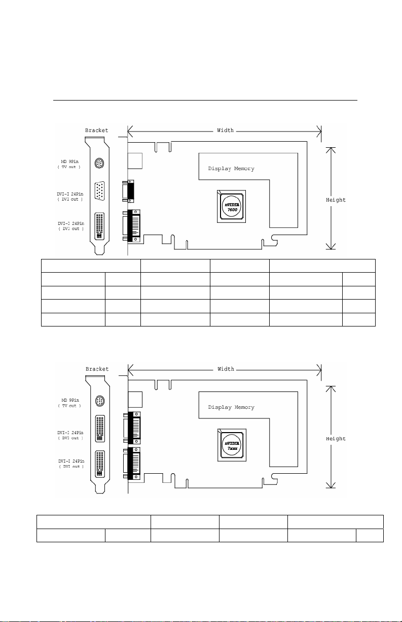
Hardware Description
Product name / PCB version Core Chipset PCB Size Memory Size
Video-PX7600GS 82378A nVIDIA GeForce 7600GS W=6.6” X H=4.376” 16M*16 x 4 DDR2 BGA 128MB
Video-PX7600GS-256 82378A nVIDIA GeForce 7600GS
Video-PX7600GS-256 82378A nVIDIA GeForce 7600GS
Video-PX7600GS-512 82378A nVIDIA GeForce 7600GS
W=6.6” X H=4.376”
W=6.6” X H=4.376”
W=6.6” X H=4.376”
16M*16 x 8 DDR2 BGA 256MB
32M*16 x 4 DDR2 BGA 256MB
32M*16 x 8 DDR2 BGA 512MB
Product name / PCB version Core Chipset PCB Size Memory Size
Video-PX7600GT 82368A nVIDIA GeForce 7600GT
7
W=6.875” X H=4.376”
16M*32 x 2 DDR3 BGA 128MB
Page 8
Video-PX7600GT-256 82368A nVIDIA GeForce 7600GT
Video-PX7900GT-256 P455 / 82388 nVIDIA GeForce 7900GT
W=6.875” X H=4.376”
W=7.8” X H=4.376”
16M*32 x 4 DDR3 BGA 256MB
8M*32 x 8 DDR3 BGA 256MB
Accessories for VGA cards are sold separately. Please go to http://Store.anvshopper.net for details.
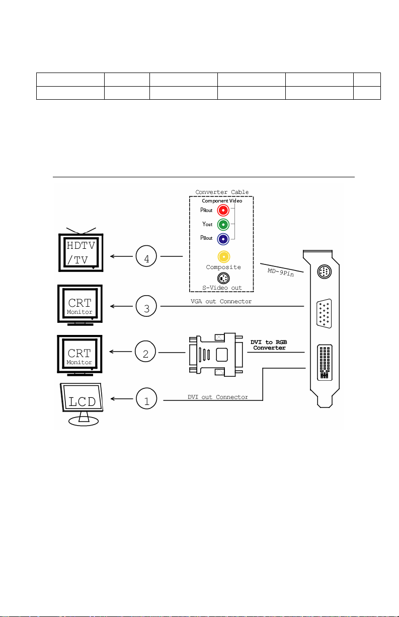
Display Devices Output
1. DVI out - DVI connects to LCD display panel.
2. DVI converts to RGB with DVI-RGB converter for VGA out.
3. VGA out - VGA connects to CRT monitor.
4. TV-Out – MD 9pin connector for Component, S-Video or Composite Out.
8
Page 9

1. DVI out - DVI connects to LCD display panel.
2. DVI converts to RGB with DVI-RGB converter for VGA out.
3. DVI out - DVI connects to LCD display panel.
4. DVI converts to RGB with DVI-RGB converter for VGA out.
5. TV-Out – MD 9pin connector for Component, S-Video or Composite Out.
9
Page 10

Hardware Installation
Installation Procedures
!! WARNING!!
Discharge static electricity by
touching the GROUND such
as metal part of your case
connected with good power
ground before you handle the
electronic circuit boards.
The manufacturer assumes no liability for any damage, caused directly
or indirectly, by improper installation of any components by unauthorized
service personnel. If you do not feel comfortable performing the
installation, consult with a qualified computer technician
.
Steps:
1. Turn OFF all powers to your system, including any peripherals (printer,
external drives, modem, etc.).
2. Disconnect the power cord and the monitor cable from the back of the
computer.
3. Unfasten the cover mounting screws on your system and remove the
system cover. Refer to your system user manual for instructions to
determine the location of the mounting screws.
4. Remove the retaining screw that holds the slot cover in place. Slide
the slot cover out and put the screw aside (you will need it to secure
the adapter).
5. To install the adapter in PCI-E expansion slot, carefully line up the
gold-fingered edge connector on the adapter directly above the
expansion slot connector on the motherboard. Then press the adapter
into place, completely. Use the (remaining) screw you removed to
secure the adapter-retaining bracket in place.
6. Replace the computer cover. Secure the cover with the mounting
screws you removed in Step 3.
You have now completed the installation of your new graphics adapter on your
system.
10
Page 11

Upgrade Steps:
Add or change your video adapter to an existing system, you
may precede a few steps before you install the new hardware
and software (video display driver). The followings are some of
the considerations:
1. To add a new adapter, ensure the mainboard has available
IRQ for new devices, and there is no conflict between each
other.
2. If you try adding this video adapter to an ALL-IN-ONE
mainboard (which video port built-in already), then you have
to disable that port first. Otherwise, that will be a problem for
the new video adapter setup.
3. The driver installation for system upgrade is the same as
below, if error occurs when you proceed to step 1, 2 or 3,
please consult with your system dealer or the existing
hardware manufacturer support.
Software Installation
á
Windows® XP/2000 Driver Installation
InstallShield® Program:
Microsoft Windows® XP/2000 detects this new hardware and places
appropriate display driver from its system folder automatically - it doesn’t
matter if you have added a new driver or changed the existing one. To
maximize the video board acceleration and increase its performance,
you may install the manufacturer’s display driver as follows:
11
Page 12

1.
Autorun feature brings-up the “Welcome Screen”, and you may
point to “Display Driver” and then press on it.
2.
Microsoft InstallShield® Wizard has start loading its setup process;
please wait until it has completed.
12
Page 13

Click on “Next” to continue the process.
3.
4.
The Windows system will copy all driver files from source media to
your local hard disk; please wait until the process has completed.
13
Page 14

Click on “Finish” to restart your computer, the new display driver will
5.
be in place after Windows boots-up.
Notice:
We believe that the all the installation steps mentioned above
are clear from manufacturer software’s CD to your operating
system. Any procedures other than these processes have not
been specified.
Technical Assistance
Q: Why is the display shifted or changed sizes when I switch display modes?
Explain and Suggestion:
Some monitors lack auto-sizing features or just do not synchronize properly to
the video board output. In some cases, horizontal and vertical display
adjustments may be necessary. Use the monitor control panel functions to adjust
screen.
In other cases, mode type and refresh rate adjustments may be necessary. Use
the utility program, which provided by video card manufacturer or production
14
Page 15

developer. To center the display with normal type (mode 3), and to reduce
(decrease) the refresh rate with the monitor's specification.
Q: What kind monitors can display 800x600 modes or higher resolution mode?
Explain and Suggestion:
To display 800x600 resolution at 60Hz refresh rate, the monitor must be capable
of synchronizing a 31.5KHz horizontal scan rate (e.g., NEC 2A, 3D). At 72Hz
refresh rate, the monitor must be capable of synchronizing a 48.0KHz scan rate
(e.g., Sony HG 1304, NEC 4D, 5D, Seiko 1450).
To display 1024x768 interlaced mode; the monitor must be capable of
synchronizing a 35.5KHz horizontal scan rate (e.g., NEC 3D, Seiko 1430 or
1440). To display 1024x768 non-interlaced mode at 60Hz, the monitor must be
capable of synchronizing a 48.7KHz scan rate (e.g., Sony HG 1304, NEC 4D,
5D, Seiko 1450).
To display 1024x768 non-interlaced mode at 70Hz, the monitor must be capable
of synchronizing a 56.4KHz scan rate (e.g., NEC 4D).
Q: System hangs-up after installing video driver.
Explain and Suggestion:
Today, most video drivers are developed for 32-bit processing and may require a
channel to Code/Decode. Conflict between device drivers and TSR (terminateand-stay-resident) programs will inverted the display, and are particularly
effectual at crashing computer. The most effective way to check for conflicts is to
replace with the original video driver, or delete and re-install the current video
driver to the system.
Accomplishing IRQs (Interrupt Request Query) settings or troubleshooting the
conflicts on hardware source may necessary. Most AGP video cards designed for
Plug-n-Play, that means video card IRQ's setup which controls by main board’s
(motherboard) circuitry and BIOS. Physically pulling out other devices from
system, and re-starts the computer. Confirm and modify your IRQ addresses with
qualified computer technician.
Q: Multiple images or unreadable screen after loading video driver.
Explain and Suggestion:
There are a variety of reasons why the display might be distorted. One common
reason is a monitor mis-match. Some older multi-frequency monitors are unable
to switch video modes without being turned off, then turned on again.
If the problem occurring in windows, make sure that you have loaded that proper
video driver, and that the driver is compatible with the monitor being used. Try reconfiguring your application software to use a compatible video mode. If problem
persist in windows, load the standard generic VGA driver. The generic VGA
15
Page 16

driver should function properly with virtually every video board and VGA (or
SVGA) monitor available.
If that is an unsatisfactory solution, you may have to upgrade to a monitor that
supports the desired video mode.
Some new monitors are also synchronizing this problem because built-in DDC
(Data-Digital-Channel) feature. Sometime that DDC automatically setup the
display frequency without loading video driver. Try to turn it off, or change
settings of monitor type in your system.
Q: Selection of color, resolution and refresh rate combination that always backs
to default after restart the system.
Explain and Suggestion:
Accordingly, there must be a bug (defected source-code) in video driver, or in the
system. Debug the source-code or fix the error in video driver that should be
done by the driver developer. Likewise, upgrade the video driver from the
manufacturer or from the original software developer is necessary.
Pinout and Sync Frequencies
Analog Color Display Pinouts (DB 15)
PIN FUNCTION
1
Red Video1
2
Green Video1
3
Blue Video1
4 Not Used
5 Ground
6 Red Return (ground)
7 Green Return (ground)
8 Blue Return (ground)
9 Vcc (+5v DDC Power)
10 Sync Return (ground)
11 Monitor ID (not used)
12 SDA (DDC support)
13 Horizontal Sync
14 Vertical Sync
15 SCL (DDC support)
16
Page 17

Note: Analog monochrome type monitors use green video for all video input
and ignore red and blue video.
Conversion Table: Pin Adapters
If you will be using a 9-to-15-pin adapter cable to link your 9-pin monitor
connector to the 15-pin accelerator card connector, check Table carefully before
you install the cable. The 9-to-15 pin adapter cables are available from a variety
of sources, but they need to match the specifications in Table to work properly
with your new card.
The adapter cable requires a D-shaped 9 pin female connector and a D-shaped
15 pin male connector.
9-to-15 Pin Conversion Table
9 PIN SIGNALS PIN NO. 15 PIN SIGNALS PIN NO.
Red 1 Red 1
Green 2 Green 2
Blue 3 Blue 3
Horz Sync 4 Horz Sync 13
Vert Sync 5 Vert Sync 14
Red Ground 6 Return Red 6
Green Ground 7 Return Green 7
Blue Ground 8 Return Blue 8
Sync Ground 9 Digital Ground 10
Analog Video Signals
Ground 5
Black Level = 0 V
Full Intensity (White) Level = +0.7 V
Digital Visual Interface (DVI-I) Connector
1 8 C1 C2
17 24 C3 C4
17
Page 18

24 pin DVI FEMALE connector built-in onboard.
Pin Number Signals
1 TMDS Data 2 2 TMDS Data 2 +
3 TMDS Data 2 Shield
4 No Connection
5 No Connection
6 DDC Clock
7 DDC Data
8 No Connection
9 TMDS Data 1 10 TMDS Data 1 +
11 TMDS Data 1 Shield
12 No Connection
13 No Connection
14 +5 V Power
15 Ground (for +5 V)
16 Hot Plug Detect
17 TMDS Data 0 18 TMDS Data 0 +
19 TMDS Data 0 Shield
20 No Connection
21 No Connection
22 TMDS Clock Shield
23 TMDS Clock +
24 TMDS Clock <
Technical Support
In the event you have a technical problem with this product, please
read the README files in the software CD_ROM. Updated drivers are
18
Page 19

available through Jaton Web site. Have following information handy
when you contact technical support:
; Name of the product.
; Software Driver and Version.
; System Information, such as CPU speed, BIOS version, Monitor
Specification, etc.
; Description of the problems including any error messages.
Telephone:
FAX:
email:
Website:
(408) 934-9369 (Mon. - Fri. 9am-5pm PST)
(408) 942-6699
vgasupport@jaton.com
www.jaton.com
How to Obtain Warranty Service
In the worldwide contact:
www.jaton.com
In United States contact:
Jaton Corporation.
Service Center
556 S. Milpitas Blvd.,
Milpitas, CA 95035
(408)-934-9369
In Thailand contact:
Jaton (Thailand) Co., Ltd.
93, 93/1-2 Moo 4 Thana City PC Tower 1
KM.14
Bangchalong Bangplee Samutprakarn 10540
Thailand
st
Fl. Bangna-Trad
19
Page 20

Tel: 662-336-1212
Fax: 662-336-1213
Tech Support: 662-336-0818
In Taiwan contact:
In Australia contact:
Jaton Technology pty, Ltd.
Unit 8, 41-49 Norcal Road,
Nunawading, Vic 3131 Australia
Tel: (Mel) 03 9873 3999 (Syd) 02 9476 8781
Fax 03 9873 3933
FCC SHIELDED CABLE WARNING:
This equipment has been tested and found to comply with the limits for a Class B digital
device, pursuant to Part 15 of the FCC Rules. Operation is subject to the following
conditions: (1) this device may not cause harmful interference, and (2) this device must
accept any interference received, including interference that may cause undesired
operation,
“SHIELD INTERFERENCE CABLE (S) MUST BE USED ACCORDING TO FCC 15.27©.”
CAUTION:
Changes or modifications not expressly approved by the Manufacturer could void your
authority to operate this equipment in accordance with FCC rules and regulations.
20
Page 21

SOFTWARE LICENSE AGREEMENT:
The Company grants the customer a non-exclusive, non-transferable license to use the
software in this package for internal use on a single computer system. No other license of
any kind is granted to any part of the product or any of the intellectual property therein.
Limited Warranty
Manufacturer warrants that the products sold hereunder are free
from defects in material and workmanship for a period of two (2)
years from manufacturing date. This limited warranty applies
only to the original purchaser of Jaton Product and is not
transferable. This limited warranty does not apply if failure to the
Product Registration, or over thirty (30) days from purchase
(original invoice date). This Limited Warranty does not cover any
incompatibilities due to the user’s computer, hardware, software
or any related system configuration in which the Jaton Products
interfaces. Proof of purchase will be requiring before any
consideration by Manufacturer occurs.
TRADEMARK AND COPYRIGHT:
This product incorporates copyright protection technology that is
protected by U.S. patents and other intellectual property rights. Use of
this copyright protection technology must be authorized by Macrovision,
and is intended for home and other limited viewing uses only unless
otherwise authorized by Macrovision. Reverse engineering or
disassembly is prohibited.
All Trademarks and Registered Trademarks belong to respective
owners.
©2006 Jaton Corporation. All rights reserved.
21
Page 22

Other Limits
The forgoing is in lieu of all other warranties, expressed or
implied. Including but not limited to the implied warranties
of merchantability and fitness for a particular purpose.
Manufacturer does not warrant against damages or defects
arising out of improper or abnormal use of handling of the
products; against defects or damages arising from improper
installation (where installation is by persons other than
Manufacturer), against defects in products or components not
manufactured or installed by Manufacturer, or against damages
result from non-manufacturer made products or components.
This warranty does not apply if accident, abuse, nor misuse has
damaged the Product. This warranty also does not apply to
products upon which repairs have been affected or attempted by
persons other than pursuant to written authorization by
Manufacturer.
Exclusive Obligation
This warranty is exclusive. The sole and exclusive obligation
of Manufacturer shall repair or replace the defective products in
the manner and for the period provided above. Manufacturer
shall not have any other obligation with respect to the Products
or any part thereof, whether based on contract, tort, and strict
liability or otherwise. Under no circumstances, whether based on
this Limited Warranty or otherwise, Manufacturer shall not be
liable for incidental, special, or consequential damage.
Other Statements
Manufacturer’s employees or representatives’ ORAL OR
OTHER WRITTEN STATEMENTS DO NOT CONSTITUE
WARRANTIES, shall not be relied upon by Buyer, and is not a
part of the contract for sale or this Limited Warranty.
Terms and Conditions
Direct Jaton Customer: This warranty applies only for a
period of two (2) years from
22
Page 23

purchase date of Jaton original
invoice.
Reseller/ Vendor: This warranty applies only for a
period of two (2) years from
manufacturing date.
Registered User: This warranty applies only for a
period of two (2) years from
purchase date and register within 30
days of purchase date from legal
reseller.
Others: If the products do not conform to this
Limited Warranty (as herein above
described), Manufacturer should
charge services such as repair,
replacement whether based on its
costs. Shipping and installation of the
replacement Products or
replacement parts shall be at User’s
expanse.
Services agreement:
(1) All applicants shall complete service request form from
Manufacturer.
(2) All returned checks will be charged a $20.00 fee by
Manufacturer.
(3) All repair and replacement services allow 4-6 weeks from
the date of receiving by Manufacturer.
(4) All products without warranties require service processing
fee $20 (payment in advance), which is not refundable.
Entire Obligation
This Limited Warranty states the entire obligation of
Manufacturer with respect to the Products. If any part of this
23
Page 24

Limited Warranty is determined to be void or illegal, the
remainder shall remain in force and effect. Some states do not
allow limitation of implied warranties, or exclusive or limitation on
product incidental or consequential damages, so above limitation
may not apply to you. This warranty gives you specific legal
rights. You may have other rights, which may vary from state to
state.
This warranty applies only to this product, and is governed by
the law of the State of California.
Reducing Warranty Claim Rejections
To reduce the potential of incurring damages not covered by
Manufacturers warranties, we strongly recommend the following:
• Read your manuals before installing peripherals
and/or before making changes to the machine’s
configuration;
• Ask your dealer if there are any known problems
with the system requirements or installation
procedures for any add-on products that your are
purchasing;
• Buy industry standard products where compatibility
issue are more likely to surface;
• If you are unsure about installation for a new
product, contact your dealer’s service department.
We believe it is important for you to know and understand what
your warranty coverage provides and what it does not.
We also want you to be aware that most hardware warranties
only relate to the function of the hardware. In most cases, no
assurances are given by the manufacturer that the hardware
item will work in conjunction with any other hardware item. If a
computer product is not working because it is not compatible
24
Page 25

with another product, or because it has not been properly
installed and set-up, the manufacturer does not pay for the
service time. To help avoid these inconveniences, contact a
professional consultant that one can help you determine the
possibility of incompatibility issue before you purchase add-on or
accessories.
Warranty Service Use Only
Serial Number - ten or eleven digit code, the serial number consists of the following parts:
Packaging Type Manufactured Date Code Production Numerical Code
A 00 8 000015
Year Month
XXXXX-XXX-XX S/N: A008000015
XXXX XX XXXXXX00.0xxxx/xxxx
Product Label and Manufactured Date Code
25
 Loading...