


3DForce G-16
3DForce G-32
3DForce G-16/TV
3DForce G-32/TV
3DForce XP
multimedia accelerator
User Manual
version 6.00
Copyright © 2002 Jaton Corporation, USA.

NOTICE
The information in this document is subject to change in order to
improve reliability, design, or function without prior notice and does not
represent a commitment on the part of the company. In no event will the
company be liable for direct, indirect, special, incidental, or
consequential damages arising out of the use or the inability to use the
product or documentation, even if advised of the possibility of such
damages. No part of this manual may be reproduced or transmitted in
any form or by any means without the prior written permission of the
company.
June 2001, Rev. A
2

Contents
1. INTRODUCTION..........................................................................................5
2. FEATURES.....................................................................................................6
2.1 AGP BUS INTERFACE..................................................................................6
2.2 PERFORMANCE (@800 MH Z PIII WITH 128MB OF MEMORY).............6
2.3 3D G RAPHICS ENGINE.................................................................................6
2.4 DVD SUPPORT.............................................................................................8
2.5 V IDEO ENGINE .............................................................................................8
2.6 ADVANCED POWER MANAGEMENT........................................................9
2.7 MEMORY BUS INTERFACE.........................................................................9
2.8 DIRECT 7.0....................................................................................................9
2.9 SOFTWARE.................................................................................................10
3. CHECK LIST ...............................................................................................10
4. SYSTEM REQUIREMENTS......................................................................10
5. HARDWARE DESCRIPTION....................................................................11
5.1 BOARD LAYOUT AND SPECIFICATION..................................................11
5.2 IDENTIFY AN AGP SLOT (SHORT AND BROWN).................................11
5.3 DISPLAY DEVICES CONNECTION............................................................12
6. HARDWARE INSTALLATION..................................................................13
6.1 INSTALLATION PROCEDURES.................................................................13
6.2 STEPS: .........................................................................................................13
7. SOFTWARE INSTALLATION..................................................................14
7.1.1 Microsoft Windows ®98/Me.........................................................14
7.1.2 Microsoft Windows NT™4.0 .........................................................20
7.1.3 Microsoft Windows2000 .............................................................25
7.1.4 Microsoft WindowsXP.................................................................32
8. TECHNICAL ASSISTANCE (Q & A)......................................................38
8.1 TIPS..............................................................................................................40
9. VIDEO MODE REFERENCE TABLE........................................................41
9.1 STANDARD MODES...................................................................................41
9.2 E XTENDED MODES...................................................................................42
10. PINOUT AND SYNC FREQUENCIES ...................................................45
3

10.1 ANALOG COLOR DISPLAY PINOUTS (DB 15)......................................45
10.2 CONVERSION TABLE: PIN ADAPTERS.................................................45
10.3 9-TO-15 PIN CONVERSION TABLE.........................................................46
10.4 ANALOG V IDEO SIGNALS.......................................................................46
11. FCC SHIELDED CABLE WARNING......................................................46
11.1 TECHNICAL SUPPORT ............................................................................47
12. LIMITED WARRANTY...........................................................................48
12.1 OTHER LIMITS.........................................................................................49
12.2 E XCLUSIVE OBLIGATION.......................................................................49
12.3 OTHER STATEMENTS............................................................................49
12.4 TERMS AND CONDITIONS......................................................................49
12.5 SERVICES AGREEMENT :..........................................................................50
12.6 E NTIRE OBLIGATION..............................................................................50
12.7 REDUCING WARRANTY CLAIM REJECTIONS.....................................50
4

1. Introduction
3DForce G-16, 3DForce G-32, 3DForce G-16/TV, and 3DForce G-32/TV
are based on Trident Blade T-16/T-64 (9970) Graphics Processor
with AGP-4x and DVD playback. With 64-bit memory bus at 143 MHz
clock on AGP 2x/4x bus aggregation, the performance of these
multimedia accelerators are beneficial to brings the DVD playback in
real-time and the high density video formal expression at high pixel
rate up to 286 million per second, and that is biggest unparalleled
cost/performance graphics solution for today’s desktop application.
3DForce XP, based on Trident Blade XP (9980) Graphics Processor
with AGP-4x and DVD playback. With 128-bit memory bus at 166 MHz
clock.
The most payoff on Trident Blade T-16/T-64 (9970) and Trident
Blade XP (9980) are that integrate the advanced 2D/3D Graphics
engine, which capable of supporting with DVD, video, and digital TV
into a single chip solution. The overlying combines highly evolved per
pixel 3D graphics engine setup and rendering with 2D graphical user
interface (GUI) acceleration can blend the high speed low latency
access on 256-bit totally. Taking expediency of AGP’s Direct Memory
Access (DMA) to retrieve textures from main memory, textures are no
longer limited by local memory.
Trident Hardware Assisted MPEG-2 Architecture (THAMA™) enables
DVD playback support to the multimedia PC. Compared to software
only DVD players, the combination of software based decode and
hardware based motion compensation delivers smooth frame rates
without overloading the processor, requires no extra frame buffer and
minimum AGP bandwidth.
The TVout choice supports an 8-bit Digital output to standard
NTSC/PAL encoder and its interface. In TVout optional livelihood, the
3DForce G-16/TV or 3DForce G-32/TV also offers independent control
interface ready for TV set output and with interlace/non-interlace
scanning capability.
For maximum throughput, the 3DForce G-16/G-32/XP use full AGP
2x/4x bus interface that supports at up to 1.06 GByte per second
transfer rate. Furthermore, 3DForce G-16/G-32/XP are subsistence
Microsoft graphics standard - DirectX 7.0 Cubic mapping, and PC2001
compliant.
Jaton Corporation, USA.
5

2. Features
2.1 AGP Bus Interface
• Full AGP 2X/4X Support at up to 1.06 GByte/sec transfer
rate
• DMA bus mastering support with Scatter Gather
• Execute Mode for Direct Textures, Video, and DVD
• Special impedance matching circuit for AGP-4X signaling
2.2 Performance (@800 MHz PIII with 128MB of
memory)
• Pixel processing rate: 800 Million pixels/sec
• Texel access rate: 1,200 Million pixels/sec
• Supports 32MB of SDRAM at up to 143 MHz memory
clock
• Up to 270 MHz RAMDAC for 1600x1200 resolution
• DVD playback in real-time (30fps) with 75% of CPU
headroom
2.3 3D Graphics Engine
2.3.1.1.1 Setup
− Up to 166 MHz clock
− Hardware interface to Direct 7.0
− 32-bit IEEE Floating Point Input Date
− 1/16 Sub-Pixel positioning accuracy for butter
image quality
6

2.3.1.1.2 Rendering
−
− Dual independent 128-bit pixel pipelines (256-bit
− Single-pass processing of diffused, specular
− Enhanced Gouraud Shading & Phong-like
− Fast order-independent scene anti-aliasing
− Fully OpenGL-compliant blending including fog
− Hidden surface removal with 16, 24, or 32-bit Z
− Color format includes 16, 24, or 32-bit per pixel
− Supports 8-bit stencil buffer
2.3.1.1.3 Texturing
− Single-pass processing of up to 4 textures per
total)
lighting and fog
environmental lighting
support
& depth cueing
buffer or W buffer
clock
− Single-pass Bi-linear, Tri-linear and Anisotropic
texture filtering
− Non-linear magnification and sharpening texture
filtering
− Multi-format texture cache
− Palletized texture format of 1, 2, 4, and 8-bit per
pixel
− Non-palletized texture of 16 or 32-bit per pixel
− Pallete data format with 565, 1555 or 4444 for
ARGB
7

− Texture color keying & enhanced filtering for
2.3.1.1.4 2D GUI
− 128-bit graphics engine
− 8/15/16/24/32-bit per pixel color formats
− 256 Raster Operations (ROPs)
− Hardware support for all 2D functions (BitBLT,
− Panning, scrolling, clipping, color expansion,
− Built-in 32x32 and 64x64 Hardware Cursor
2.4 DVD Support
• THAMA™ architecture enables full DVD player support
• Requires no extra frame buffer and minimum AGP
bandwidth
• Includes both Motion Compensation and IDCT hardware
assist
translucent objects
lines, polygons, fills, patterns, clipping, bit
masking…)
sprites
• Real-time playback (30fps) of 9.8 Mbps MPEG-2 video
bitstream with 80% CPU headroom for other application
• Alpha blending for subpicture
• Advanced error recovery & concealment
• Programmable multi-tap filtering
• Pan and scan support
• Anti-tearing support
• Supports DVD version 1.0 and VCD version 2.0
2.5 Video Engine
• State-of-art video de-interlacing
8

• Capable of supporting HD0 HDTV resolution (1280x720)
• TrueVideo® bilinear interpolation with proprietary edge
recovery scaling
• Dual apertures for simultaneous access to graphics and
video display memory area
• Dual color space converters (CSC)
• Accelerates YUV planar format
2.6 Advanced Power Management
• 7 GPIOs, suspend and standby modes
• Internal clock gating on each functional block
• PCIPM (H/W PCI initiated)
• AGP Clock Busy/Stop and PCI Clock Run
• ACPI and DPMS support
2.7 Memory Bus Interface
• Up to 128-bit SDRAM/SGRAM memory bus at 166 MHz
clock
• Up to 32 Mbytes of local frame buffer
2.8 Direct 7.0
• Microsoft graphics standard for Windows 2000
• hardware support of Cubic mapping reflections, refraction
and lighting
• Hardware support of environment and emboss bump
mapping
• Hardware support of texture compression
• Hardware support of all data formats for setup processing
• Adaptive sharing of Transform & Lighting processing
with CPU
9

2.9 Software
• Window 98/Me, Window 2000/XP
• Windows NT 4.0
• DirectX 6.0, 7.0 and 8.0
• DirectShow 3.0 and 4.0
• OpenGL ICD 1.0 and 1.2
3. Check List
The package you have purchased should contain the following:
þ 3DForce G-16, or 3DForce G-16/TV, or 3DForce
G-32, or 3DForce G-32/TV, or 3DForce XP
multimedia accelerator
þ Software and Documentation CDs
þ Quick Start Guide (Printed)
If any of these items is missing or damaged, contact your dealer.
IMPORTANT: Keep all packaging materials that accompany your
adapter in the event you need to return the product.
4. System Requirements
• Intel or compatible Pentium® II system with an AGP-2x/4x Bus
Extension Slot
• CD-ROM drive, Double speed or faster
• Hard Drive with at least 10MB Free space
• Mouse, Sound Card and Speaker optional
• MS Windows®98/Me, Windows® NT4.0, Windows2000, and
Windows XP operating system
10
5. Hardware Description
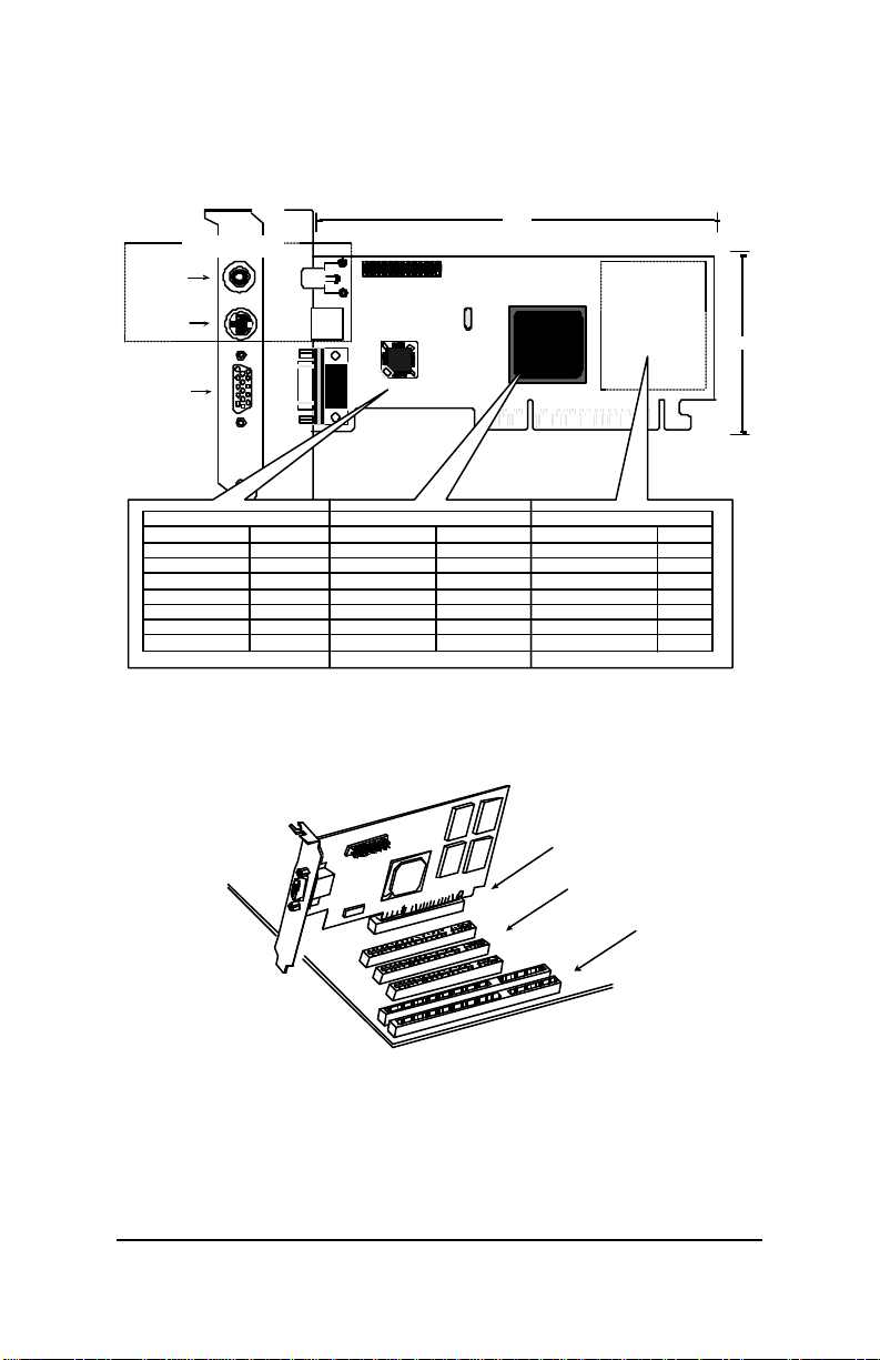
5.1 Board Layout and Specification
Plate
TVOUT OPTIONAL
RCA Video
2
1
26
25
Width
S_Video
DB 15 VGA
Y1
Trident
Blade-Txx
AGP 2x4x BUS
Product's Name / PCB version Core Chipset / PCB size Memory Module / Size
3DForce G-16
3DForce G-16TV
3DForce G-32
3DForce G-32TV
3DForce XP
82117B
82117B
82117B
82117B
82127B
Trident Blade T-16
Trident Blade T-16
Trident Blade T-64
Trident Blade T-64
Trident Blade XP
W = 6.3" x H = 3.3"
W = 6.3" X H = 3.3"
W = 6.3" X H = 3.3"
W = 6.3" X H = 3.3"
W = 6.5" X H = 3.5"
2M X 16 SDRAM X 4
2M X 16 SDRAM X 4
4M X 16 SDRAM X 4
4M X 16 SDRAM X 4
2M X 32 SDRAM X 4
5.2 Identify an AGP Slot (short and brown)
AGP adapter
AGP Slot
PCI Slots
Display Memory
ISA Slots
16MB
16MB
32MB
32MB
32MB
Height
Main board
11
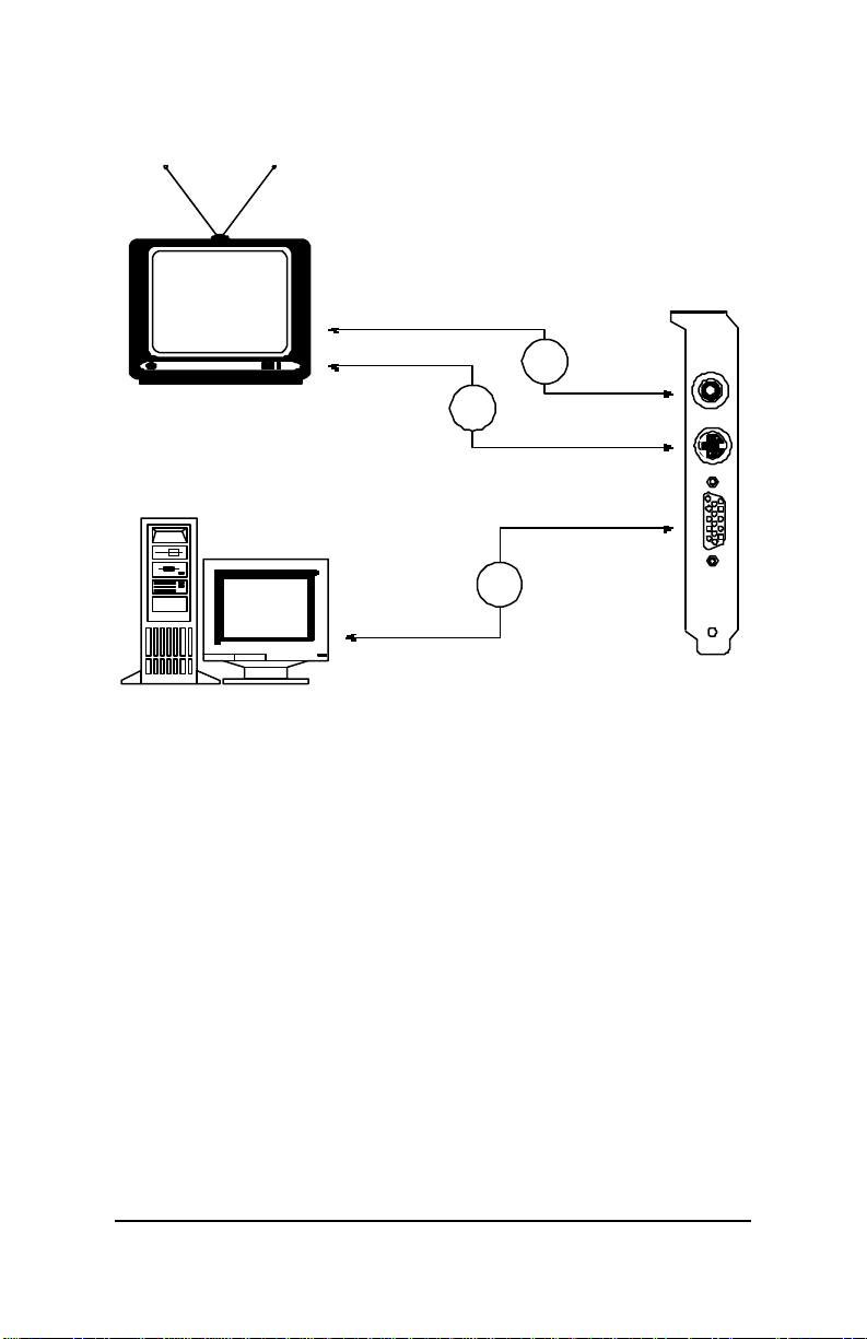
5.3 Display Devices Connection
AGP Plate
Television
PC Computer
1
2
3
RCA Video
Connector
S_Video
Connector
DB 15 VGA
Connector
1. If your system is equipped with a sound board, you can also
connect a Y-cable for speaker (single male mini stereo phono jack to
double male RCA jack) from the Speaker-Out jack of the sound
board to the Audio-In jack on your television set.
2. For optional TV connection, please check the back of your TVset or
VCR for a S-Video connector. If such a connector is present, you
will need a S-Video cable to adjoin S-Video TV-Out on the adapter
to S-Video In on the TV or VCR. If such a connector is not
available, a RCA video cable is needed to link Composite TV-Out
on the adapter to Composite Video In on the TV or VCR. S-Video
connection is recommended since it provides a higher quality
display.
3. Connect your monitor to the adapter standard VGA 15-pin analog
connector. Be sure you have the right cable and cable connector.
For complicated connection (connect more devices between the TV and
video card) that may required different layout and accessories. Please
ask qualified technician or consultant for the details.
12
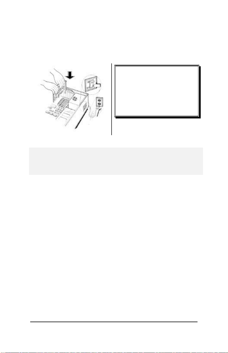
6. Hardware installation
6.1 Installation Procedures
!! WARNING !!
Discharge static electricity by
touching the GROUND such as
metal part of your case connected
with good power ground before
you handle the electronic circuit
boards.
The manufacturer assumes no liability for any damage, caused
directly or indirectly, by improper installation of any components by
unauthorized service personnel. If you do not feel comfortable
performing the installation, consult with a qualified computer
technician.
6.2 Steps:
1. Turn OFF all powers to your system, including any
peripherals (printer, external drives, modem, etc.).
2. Disconnect the power cord and the monitor cable from the
back of the computer.
3. Unfasten the cover mounting screws on your system and
remove the system cover. Refer to your system user manual
for instructions to determine the location of the mounting
screws.
4. Remove any graphics adapter that already installed on your
motherboard. Start by removing the screw that holds the
adapter retaining bracket in place (keep this screw, you will
need it later). Then, gently pull straight up on the adapter card
itself, and remove it from the motherboard.
5. Refer to your computer system manual for the location of the
AGP bus expansion slots. Remove the retaining screw that
holds the slot cover in place. Slide the slot cover out and put
the screw aside (you will need it to secure the adapter).
If you just removed an existing graphics adapter and are not
13

going to use that expansion slot, you can install the slot cover
you just removed from the unused expansion slot to cover the
open hole.
6. To install the adapter in the selected expansion slot, carefully
line up the gold-fingered edge connector on the adapter
directly above the expansion slot connector on the
motherboard. Then press the adapter into place, completely,
with necessary but minimum pressure. DO NOT USE
excessive force. Use the (remaining) screw you removed to
secure the adapter retaining bracket in place.
7. Replace the computer cover. Secure the cover with the
mounting screws you removed in Step 3.
You have now completed the installation of your new graphics adapter
on your system.
7. Software Installation
7.1.1 ÿÿ M ICROSOFT WINDOWS ®98/ME
When you powered the computer and boots-up in the Windows,
the Plug-n-Play detects a new hardware and pops-up install
wizard. Do Not [Cancel] because you need place a default
display setting from Microsoft Windows for your video adapter,
then restart your Windows. After the desktop loaded completely,
insert the software’s CD into CD ROM drive and proceed the
display driver installation that provided from Video Adapter
manufacturer..
14
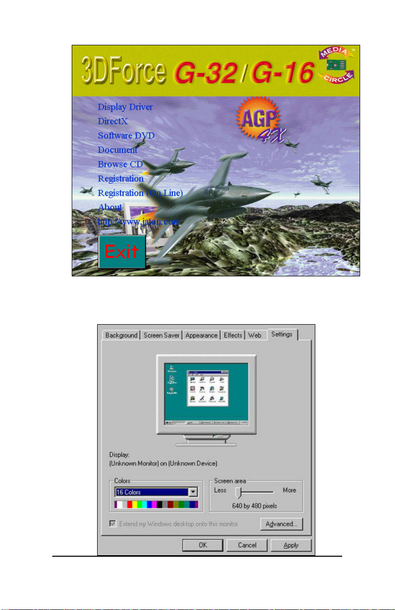
1. Autorun feature pops-up “Welcome” screen as below, then you
may click on “Display Driver” selectable text to start the
installation.
15
2. Click on Settings tab, then click on Advanced…button in lower
portion of tab screen.
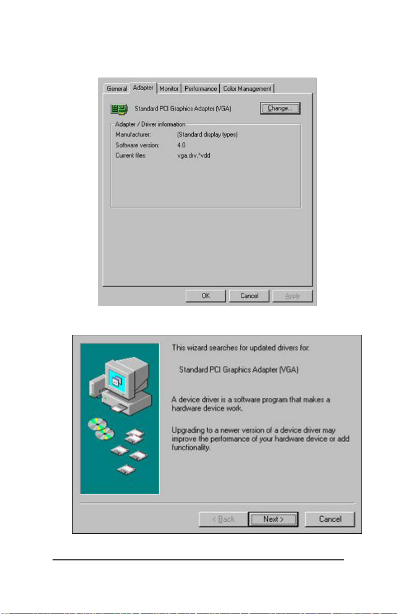
3. Select Change… button in Adapter tab screen.
16

4. Install wizard will searching an updated driver for standard VGA
adapter. Click the Next button now.
5. Click on Next button with “Specify the location driver (Advanced) “
option to continue.
17

6. Click on Next button with “Display a list of all the drivers in a
specific location, so you can select the driver you want” selectable
option.
7. Obedient to the select device page, press on "Have Disk..." button
to specify the location of drivers.
8. You can input D:\G1632&XP\WIN9X into the dialog box, and click
on OK button. (Where D is drive letter of your CD_ROM drive. If D
is not your CD-ROM drive, substitute D with the correct drive
letter.) Or, you can browsing on CD and unfold these folders then
click on OK button.
18

9. Install wizard selected on "3DForce G-16/G-32/TV/XP (Trident
Video Blade XP/T64)" to install, you may click on OK button.
10. Click Next to start transmit all driver files from software CD to your
local hard disk drive.
19

11. Click Finish to close the install wizard screen after all files have
been copy over.
7.1.2 ÿÿ M ICROSOFT WINDOWS NT™4.0
Note: The procedure of display driver installation that is required
“setup” with service pack4 or above (Microsoft® Windows NT™4.0)
before install the video display driver.
After Windows desktop loaded completely, place software CD from
manufacturer into your CD ROM drive, then Autorun brings up the
“Welcome” screen as below.
20

1. SELECT on the “Display Driver” from the picture above.
2. TAB, or CLICK on the “Settings” screen page.
21

3. SELECT “Display Type...” button in the “Settings” page.
4. SELECT “Change...” button from the Adapter type section.
22

5. SELECT “Have Disk...” button from the Change Display page.
6. Microsoft Windows NT 4.0 will prompt you for the correct path where the
video drivers are located. ENTER “D:\G-32&XP\Winnt4\” where D: is the
letter of your CD ROM drive that the Software & Documents CD has been
inserted. Click on “Open” button to continue.
23

7. Click on “OK” button, if the file source for driver is corrected.
8. If the driver “3DForce G-16/G-32/TV/XP (Trident Video Blade-
XP/T64)” is listed under the Display list, SELECT the “OK” button to
continue.
24

9. A screen message prompt that the conformation of your display driver has
been in place for the new hardware. Click on “Yes”.
10. Click on “OK”. Once the driver files are copied, RESTART Microsoft
Windows NT 4.0 for the changes to take effect.
7.1.3 ÿÿ M ICROSOFT WINDOWS 2000
Microsoft Windows® XP detects this device and
placed appropriate display driver from its
operating system automatically, it doesn’t
matter you have add a new or change the existing
one. To maximum the video board acceleration and
breadth its performance, you may install the
manufacturer display driver as the followings:
Insert the software CD into your CD ROM, and …
25

1. Aoturun brings up the “Welcome” screen for
your new display driver installation, click
on “Display Driver” from this picture above.
2. Add New Hardware Wizard will pops-up, click
on “ Next” to start the installation.
3. Checked “Add/Troubleshooting device” and
click on “Next” to continue.
26

4. Wizard has been found the new device, click
on “Next” to continue.
5. Place the check mark to “search device from a
list” then click on “Next”.
27

6. High light “Display adapter” and click on
“Next”.
7. Wizard ask you to select device driver from
its table, do not take any of them from that
list. Click on “Have disk…” button to
continue the process.
28

8. Browse and unfolded on CD sub-directories, or
type “D:\G1632&XP\Win2000” into dialog box as
above, then click on “OK”. (D is the letter
of your CD_ROM drive, typically, D or E
drives, etc.)
9. A confirmation screen for the device you have
selected, click on “Next” to continue the
installation.
29

10. A confirmation for digital signature was not
embody all driver files (not necessarily to
have that signature), click on “Yes” to
continue installation.
11. Windows operating system will copying all
30

files to the designation (local hard drive)
drive. Click on “Next” now.
12. File transmission has been progress, please
wait until it finished.
13. Click on “Finish” to complete the driver
install process.
31

14. Re-boot your computer is required for new
display driver in places.
7.1.4 ÿÿ M ICROSOFT WINDOWS XP
Microsoft Windows® XP detects this device and
placed appropriate display driver from its
operating system automatically, it doesn’t
matter you have add a new or change the existing
one. To maximum the video board acceleration and
breadth its performance, you may install the
manufacturer display driver as the followings:
Insert software CD into your CD_ROM, and …
32

1. Aoturun brings up the “Welcome” screen for
your new display driver installation, click
on “Display Driver” from this picture above.
2. Add New Hardware Wizard will pops-up, click
on “ Next” to start the installation.
33

3. Wizard searches the Plug-and-Play device
information from its database.
4. Wizard has been found the new device, click
on “Next” to continue.
5. Place the CD from manufacturer into your CD
ROM drive, browse and unfolded on sub-
34

directories, or type in “E:\G1632&Xp\winxp”
into dialog box as above, then click on
“Next”.
6. Wizard searches the source files for the new
device.
35

7. Wizard has been listed the device to install,
click on “Next” to continue the process.
8. A conformation screen that prompts to ensure
36

the progress, click on “Continue Anyway”.
9. Windows operating system starts copy all
files to the designation (local hard
drive)drive.
37

10. Click on “Finish” to complete the driver
installation.
8. Technical Assistance (Q & A)
Q: Why is the display shifted or changed sizes when I switch
display modes?
A:
Some monitors lack auto-sizing features or just do not
synchronize properly to the video board output. In some cases,
horizontal and vertical display adjustments may be necessary.
Use the monitor control panel functions to adjust screen.
In other cases, mode type and refresh rate adjustments may be
necessary. Use the utility program which provided by video card
manufacturer or production developer. To centering the display
with normal type (mode 3), and to reduce (decrease) the refresh
rate with the monitor’s specification.
Q: What kind monitors can display 800x600 mode or higher
resolution mode?
A:
To display 800x600 resolution at 60Hz refresh rate, the monitor
must be capable of synchronizing a 31.5KHz horizontal scan rate
(e.g., NEC 2A, 3D). At 72Hz refresh rate, the monitor must be
capable of synchronizing a 48.0KHz scan rate (e.g., Sony HG
1304, NEC 4D, 5D, Seiko 1450).
To display 1024x768 interlaced mode, the monitor must be
capable of synchronizing a 35.5KHz horizontal scan rate (e.g.,
NEC 3D, Seiko 1430 or 1440). To display 1024x768 noninterlaced mode at 60Hz, the monitor must be capable
of synchronizing a 48.7KHz scan rate (e.g., Sony HG 1304, NEC
4D, 5D, Seiko 1450).
To display 1024x768 non-interlaced mode at 70Hz, the monitor
must be capable of synchronizing a 56.4KHz scan rate (e.g., NEC
4D).
38

Q: Windows screen won’t come up, it kicks back to
DOS prompt. Why?
A:
The SYSTEM.INI file may contain different information with the
system hardware, cause by the new integration or the new
installation of a video adapter. The SYSTEM.INI file is located in
the WINODWS\SYSTEM directory. Use MS DOS editor to open
the file, and change the statement that is under [Boot description]
section:
display.drv= VGA then save changes, and restart Windows.
Or, Under
DOS prompt, type within Windows “SETUP” , change the display
selection to VGA then exit and restart Windows.
Windows 9x
Inadvertently, certain configuration files (e.g., msdos.sys,
command.com) have been changed in the system. Proceed to
correct that, is re-boot the system with a system (Windows 9x)
formatted floppy diskette.
There are many reasons to causing the system booting-up with
un-appropriated steps. Base on Microsoft support wizard on
their WEBsite, there are many technical articles to help users
with this subject, such as troubleshooting with VXD errors, virus,
Fatal exceptions, etc., more details cover on each issue are
descriptive and familiar with, and exclusively further to our support.
Q: System hangs-up after installing video driver.
A:
Today, most video drivers are developed for 32-bit processing and
may require a channel to Code/Decode. Conflict between device
drivers and TSR (terminate-and-stay-resident) programs will
inverted the display, and are particularly effectual at crashing
computer. The most effective way to check for conflicts is to
replace with the original video driver, or delete and re-install the
current video driver to the system.
Accomplishing IRQs (Interrupt Request Query) settings, or
troubleshooting the conflicts on hardware source may necessary.
39

Most PCI/AGP video cards designed for Plug-n-Play, that means
video card IRQ’s setup which controls by main board’s (mother
board) circuitry and BIOS. Physically pulling out other devices
from system, and re-start the computer. Confirm and modify your
IRQ addresses with qualified computer technician.
Q: Multiple images or unreadable screen after loading video driver.
A:
There are a variety of reasons why the display might be distorted.
One common reason is a monitor mismatch. Some older multifrequency monitors are unable to switch video modes without
being turned off, then turned on again.
If the problem occurring in windows, make sure that you have
loaded that proper video driver, and that the driver is compatible
with the monitor being used. Try re-configuring your application
software to use a compatible video mode. If problem persist in
windows, load the standard generic VGA driver. The generic VGA
driver should function properly with virtually every video board and
VGA (or SVGA) monitor available.
If that is an unsatisfactory solution, you may have to upgrade to a
monitor that support the desired video mode.
Some new monitors are also synchronizing this problem because
built-in DDC (Data-Digital-Channel) feature. Sometime that DDC
automatically setup the display frequency without loading video
driver. Try to turn it off, or change settings of monitor type in your
system.
Q: Selection of color, resolution and refresh rate combination
that always back to default after restart the system.
A:
Accordingly, there must be a bug (defected source-code) in video
driver, or in the system. Debug the source-code or fix the error in
video driver, that should be done by the driver developer. Likewise,
upgrade the video driver from the manufacturer or from the original
software developer is necessary.
8.1 Tips
The following are some recommended steps to take if the video adapter
will not boot up or operate properly in your system:
40

1. Ensure that the monitor or TV brightness and contrast controls
are properly adjusted.
2. Check to see if your monitor or TV is properly connected to the
card. Be sure your monitor’s pin definitions match those of
your video card. For TV out, ensure that the composite signal
is connected to a “Video Input” RCA jack on the TV (or check
the S-video connection). Read the TV owner’s manual to
select the proper signal jack for the display.
3. Turn the system on and confirm that the power supply is
operating properly; i.e., that the fan operates and the system
power light turns on.
4. Check to see if the card is firmly seated in its AGP bus
expansion slot. It should not be making contact with any other
cards in the system.
Note: Turn the system off before adjusting the card.
9. Video Mode Reference Table
The adapter’s video modes include all of the following:
9.1 Standard Modes
Mode
#
0h,1h 320x200-16 31.4 70 2MB 40x25 Text NI
2h,3h 640x400-16 31.4 70 2MB 80x25 Text NI
4h,5h 320x200-4 31.4 70 2MB 40x25 Graph NI
6h 640x200-2 31.4 70 2MB 80x25 Graph NI
7h 720x350-Mono 31.5 70 2MB 80x25 Text NI
Dh 320x200-16 31.4 70 2MB 40x25 Graph NI
Eh 640x200-16 31.4 70 2MB 80x25 Graph NI
Fh 640x350-2 31.4 70 2MB 80x25 Graph NI
10h 640x350-16 31.4 70 2MB 80x25 Graph NI
11h 640x480-2 31.4 60 2MB 80x30 Graph NI
12h 640x480-16 31.4 60 2MB 80x30 Graph NI
13h 320x200-256 31.4 70 2MB 40x25 Graph NI
Resolution
-Colors
Horz
KHz
Vert
Hz
Mem
Req
Text
Res.
Mode
Type
Scan
Type
41

9.2 Extended Modes
Mode
#
50h 640x480-16 31.5 60 2M 80x43 Text NI
51h 640x473-16 31.5 60 2M 80x43 Text NI
52h 640x480-16 31.5 60 2M 80x60 Text NI
53h 1056x350-16 31.3 70 2M 132x25 Text NI
54h 1056x480-16 31.3 60 2M 132x30 Text NI
55h 1056x473-16 31.3 60 2M 132x43 Text NI
56h 1056x480-16 31.3 60 2M 132x60 Text NI
57h 1188x350-16 31.3 70 2M 132x25 Text NI
58h 1188x480-16 31.3 60 2M 132x30 Text NI
59h 1188x473-16 31.3 60 2M 132x43 Text NI
5Ah 1188x480-16 31.3 60 2M 132x60 Text NI
5Bh_1 800x600-16 37.8 60 2M 100x75 Graph NI
5Ch 640x400-256 31.6 70 2M 80x25 Graph NI
5Dh_4 640x480-256 43.2 85 2M 80x30 Graph NI
5Dh_3 640x480-256 37.5 75 2M 80x30 Graph NI
5Dh_2 640x480-256 37.8 72 2M 80x30 Graph NI
5Dh_1 640x480-256 31.4 60 2M 80x30 Graph NI
5Eh_3 800x600-256 53.7 85 2M 100x37 Graph NI
5Eh_2 800x600-256 46.8 75 2M 100x37 Graph NI
5Eh_1 800x600-256 37.8 60 2M 100x37 Graph NI
5Fh_5 1024x768-16 68.7 85 2M 128x48 Graph NI
5Fh_4 1024x768-16 60.4 75 2M 128x48 Graph NI
5Fh_3 1024x768-16 56.4 70 2M 128x48 Graph NI
5Fh_2 1024x768-16 48.5 60 2M 128x48 Graph NI
5Fh_1 1024x768-16 35.5 87i 2M 128x48 Graph I
62h_5 1024x768-256 68.7 85 2M 128x48 Graph NI
62h_4 1024x768-256 60.0 75 2M 128x48 Graph NI
62h_3 1024x768-256 56.4 70 2M 128x48 Graph NI
62h_2 1024x768-256 48.3 60 2M 128x48 Graph NI
62h_1 1024x768-256 35.5 87i 2M 128x48 Graph I
63h_4 1280x1024-16 91.1 85 2M 160x64 Graph NI
63h_3 1280x1024-16 80.0 75 2M 160x64 Graph NI
63h_2 1280x1024-16 63.9 60 2M 160x64 Graph NI
63h_1 1280x1024-16 46.4 87i 2M 160x64 Graph I
64h_4 1280x1024-256 91.1 85 2M 160x64 Graph NI
64h_3 1280x1024-256 80.0 75 2M 160x64 Graph NI
64h_2 1280x1024-256 63.9 60 2M 160x64 Graph NI
64h_1 1280x1024-256 46.4 87i 2M 160x64 Graph I
65h_2 1600x1200-16 75 60 2M 200x75 Graph I
65h_1 1600x1200-16 62.5 96i 2M 200x75 Graph I
66h_2 1600x1200-256 75 60 2M 200x75 Graph I
Resolution
-Colors
Horz
KHz
VertHzMem
Req
42
Text Res. Mode
Type
Scan
Type

Mode
#
Resolution
-Colors
Horz
KHz
VertHzMem
Req
Text Res. Mode
Type
Scan
Type
66h_1 1600x1200-256 62.5 96i 2M 200x75 Graph I
6Ah_1 800x600-16 37.8 60 2M 100x75 Graph NI
6Bh 640x400-16M 31.6 70 2M 80x25 Graph NI
6Ch_4 640x480-16M 43.2 85 2M 80x30 Graph NI
6Ch_3 640x480-16M 37.5 75 2M 80x30 Graph NI
6Ch_2 640x480-16M 37.8 72 2M 80x30 Graph NI
6Ch_0 640x480-16M 31.4 60 2M 80x30 Graph NI
6Dh_3 800x600-16M 53.7 85 2M 100x37 Graph NI
6Dh_2 800x600-16M 46.8 75 2M 100x37 Graph NI
6Dh_1 800x600-16M 37.8 60 2M 100x37 Graph NI
66h_2 1600x1200-256 75 60 2M 200x75 Graph I
6Eh_5 1024x768-16M 68.7 85 2M 128x48 Graph I
6Eh_4 1024x768-16M 60.0 75 2M 128x48 Graph I
6Eh_3 1024x768-16M 56.4 70 2M 128x48 Graph I
6Eh_2 1024x768-16M 48.3 60 2M 128x48 Graph I
6Eh_1 1024x768-16M 35.5 87i 2M 128x48 Graph I
72/3h 640x400-32K/64K 31.6 70 2M 80x25 Graph NI
74/5h_4 640x480-32K/64K 43.2 85 2M 80x30 Graph NI
74/5h_3 640x480-32K/64K 37.5 75 2M 80x30 Graph NI
74/5h_2 640x480-32K/64K 37.8 72 2M 80x30 Graph NI
74/5h_1 640x480-32K/64K 31.4 60 2M 80x30 Graph NI
76/7h _4 800x600-32K/64K 53.7 85 2M 100x37 Graph NI
76/7h_3 800x600-32K/64K 46.8 75 2M 100x37 Graph NI
76/7h_2 800x600-32K/64K 37.8 60 2M 100x37 Graph NI
78/9h_5
78/9h_4
78/9h_3
78/9h_2
78/9h_1
7A/Bh_1
1024x768-32K/64K
1024x768-32K/64K
1024x768-32K/64K
1024x768-32K/64K
1024x768-32K/64K
1280x1024-
32K/64K
68.7 85 2M 128x48 Graph NI
60.0 75 2M 128x48 Graph NI
56.4 70 2M 128x48 Graph NI
48.3 60 2M 128x48 Graph NI
35.5 87i 2M 128x48 Graph NI
46.4 85 4M 160x128 Graph I
2Ch 320x200-256 31.6 70 2M 40x12 Graph
2Dh_4 320x240-256 43.3 85 2M 40x15 Graph
2Dh_3 320x240-256 37.5 75 2M 40x15 Graph
2Dh_2 320x240-256 37.9 72 2M 40x15 Graph
2Dh_1 320x240-256 31.5 60 2M 40x15 Graph
2Eh_3 400x300-256 53.7 85 2M 50x18 Graph
2Eh_2 400x300-256 46.9 75 2M 50x18 Graph
2Eh_1 400x300-256 37.9 60 2M 50x18 Graph
3Bh 320x200-16M 31.6 70 2M 40x12 Graph
3Ch_4 320x240-16M 43.3 85 2M 40x15 Graph
3Ch_3 320x240-16M 37.5 75 2M 40x15 Graph
3Ch_2 320x240-16M 37.9 72 2M 40x15 Graph
43

Mode
#
Resolution
-Colors
Horz
KHz
VertHzMem
Req
Text Res. Mode
Type
3Ch_0 320x240-16M 31.5 60 2M 40x15 Graph
3Dh_3 400x300-16M 53.7 85 2M 50x18 Graph
3Dh_2 400x300-16M 46.9 75 2M 50x18 Graph
3Dh_1 400x300-16M 37.9 60 2M 50x18 Graph
42/3h 320x200-32K/64K 31.6 70 2M 40x12 Graph
44/5h_4 320x240-32K/64K 43.3 85 2M 40x15 Graph
44/5h_3 320x240-32K/64K 37.5 75 2M 40x15 Graph
44/5h_2 320x240-32K/64K 37.9 72 2M 40x15 Graph
44/5h_1 320x240-32K/64K 31.5 60 2M 40x15 Graph
46/7h_4 400x300-32K/64K 53.7 85 2M 50x18 Graph
46/7h_3 400x300-32K/64K 46.9 75 2M 50x18 Graph
46/7h_2 400x300-32K/64K 37.9 60 2M 50x18 Graph
NOTES:
1. VESA mode. Same as 5Bh_1.
2. The “I” and “NI” in the vertical frequency column denote “interlaced” and “Non-interlace”,
respectively.
Scan
Type
44

10. Pinout and Sync Frequencies
10.1 Analog Color Display Pinouts (DB 15)
PIN FUNCTION
1
Red Video
2
Green Video
3
Blue Video
4 Not Used
5 Ground
6 Red Return (ground)
7 Green Return (ground)
8 Blue Return (ground)
9 Vcc (+5v DDC Power)
10 Sync Return (ground)
11 Monitor ID (not used)
12 SDA (DDC support)
13 Horizontal Sync
14 Vertical Sync
15 SCL (DDC support)
1
1
1
Note: Analog monochrome type monitors use green video for all
video input and ignore red and blue video.
10.2 Conversion Table: Pin Adapters
If you will be using a 9-to-15 pin adapter cable to link your 9 pin monitor
connector to the 15 pin accelerator card connector, check Table
carefully before you install the cable. The 9-to-15 pin adapter cables are
available from a variety of sources, but they need to match the
specifications in Table to work properly with your new card.
The adapter cable requires a D-shaped 9 pin female connector and a Dshaped 15 pin male connector.
45

10.3 9-to-15 Pin Conversion Table
9 PIN SIGNALS PIN NO. 15 PIN SIGNALS PIN NO.
Red 1 Red 1
Green 2 Green 2
Blue 3 Blue 3
Horz Sync 4 Horz Sync 13
Vert Sync 5 Vert Sync 14
Red Ground 6 Return Red 6
Green Ground 7 Return Green 7
Blue Ground 8 Return Blue 8
Sync Ground 9 Digital Ground 10
Ground 5
10.4 Analog Video Signals
1. Black Level = 0 V
2. Full Intensity (White) Level = +0.7 V
11. FCC SHIELDED CABLE WARNING
This equipment has been tested and found to comply with the limits for
a Class B digital device, pursuant to Part 15 of the FCC Rules. These
limits are designed to provide reasonable protection against harmful
interference in a residential installation. This equipment generates, uses
and can radiate radio frequency energy and, if not installed and used in
accordance with the instructions, may cause harmful interference to
radio communications. However, there is no guarantee that interference
will not occur in a particular installation. If this equipment does cause
interference to radio or television reception, which can be determined by
turning the equipment off and on, the user is encouraged to try to
correct the interference by one or more of the following measures:
Reorient or re-locate the receiving antenna.
Increase the separation between the equipment and the receiver.
Connect the equipment into an outlet on a circuit different from that
46

to which the receiver is connected.
Consult an experienced radio/TV technician for help.
The user may find the following booklet prepared by the Federal
Communications Commission helpful:
“How to Identify and Resolve Radio/TV Interference Problems”.
This booklet is available from the U.S. Government Printing Office,
Washington, DC 20402, Stock No. 004-000-00345-4.
This device complies with Part 15 of the FCC Rules. Operation is subject
to the following conditions: (1) this device may not cause harmful
interference, and (2) this device must accept any interference received,
including interference that may cause undesired operation,
“SHIELD INTERFERENCE CABLE(S) MUST BE USED ACCORDING
TO FCC 15.27©.”
CAUTION: Changes or modifications not expressly approved by the
Manufacturer could void your authority to operate this equipment in
accordance with FCC rules and regulations.
11.1 Technical Support
In the event you have a technical problem with this product, please read
the README files in the software CD-ROM. Updated drivers are
available through Jaton BBS and Web site. Have following information
handy when you contact technical support:
þ Name of the product.
þ Software Driver and Version.
þ System Information, such as CPU speed, BIOS version, Monitor
Specification, etc.
þ Description of the problems including any error messages.
For Customer Service or Return Merchandise Service, please contact
Jaton service centers worldwide in your regional location.
In North America contact:
Jaton Corporation.
Service Center
556 S.Milpitas Blvd.,
Milpitas, CA 55035
(408)-942-9888 ext.151
47

In Europe contact:
Jaton Europe B.V.
Overwegwachter 3, 3034 G,
Potterdam, Netherland (Holland)
31-10-412-1154
In Thailand contact:
Jaton (Thailand) Co., Ltd.
27th Floor, Panjathani Tower
127/32 Nonsee Rd., Chongnonsee
Yannawa, Bangkok 10120
Thailand
Tel: 662-681-0388
In Taiwan contact:
In Australia contact:
Jaton Technology pty, Ltd.
Unit 8, 41-49 Norcal Road,
Nunawading, Vic 3131 Australia
Tel: 61-3-9873-3999
12. Limited Warranty.
Manufacturer warrants that the products sold hereunder are free from
defects in material and workmanship for a period of two (2) years from
manufacturing date. This limited warranty applies only to the original
purchaser of Jaton Product and is not transferable. This limited warranty
does not apply if failure to the Product Registration, or over thirty (30)
days from purchase (original invoice date). This Limited Warranty does
not cover any incompatibilities due to the user’s computer, hardware,
software or any related system configuration in which the Jaton
Products interfaces. Proof of purchase will be requiring before any
consideration by Manufacturer occurs.
48

12.1 Other Limits.
The forgoing is in lieu of all other warranties, expressed or implied.
Including but not limited to the implied warranties of merchantability
and fitness for a particular purpose. Manufacturer does not warrant
against damages or defects arising out of improper or abnormal use of
handling of the products; against defects or damages arising from
improper installation (where installation is by persons other than
Manufacturer), against defects in products or components not
manufactured or installed by Manufacturer, or against damages result
from non-manufacturer made products or components. This warranty
does not apply if the Product has been damaged by accident, abuse, nor
misuse. This warranty also does not apply to products upon which
repairs have been affected or attempted by persons other than pursuant
to written authorization by Manufacturer.
12.2 Exclusive Obligation.
This warranty is exclusive. The sole and exclusive obligation of
Manufacturer shall repair or replace the defective products in the
manner and for the period provided above. Manufacturer shall not have
any other obligation with respect to the Products or any part thereof,
whether based on contract, tort, and strict liability or otherwise. Under
no circumstances, whether based on this Limited Warranty or
otherwise, Manufacturer shall not be liable for incidental, special, or
consequential damage.
12.3 Other Statements.
Manufacturer’s employees or representatives’ ORAL OR OTHER
WRITTEN STATEMENTS DO NOT CONSTITUE WARRANTIES, shall
not be relied upon by Buyer, and are not a part of the contract for sale
or this Limited Warranty.
12.4 Terms and Conditions.
Direct Jaton Customer: This warranty applies only for a period of
two (2) years from purchase date of Jaton
original invoice.
Reseller/ Vendor: This warranty applies only for a period of
two (2) years from manufacturing date.
Registered User: This warranty applies only for a period of
two (2) years from purchase date and
register within 30 days of purchase date
from legal reseller.
49

Others: If the products do not conform to this
Limited Warranty (as herein above
described), Manufacturer should charge
services such as repair, replacement
whether based on its costs. Shipping and
installation of the replacement Products
or replacement parts shall be at User’s
expanse.
12.5 Services agreement:
(1) All applicants shall completed service request form from
Manufacturer.
(2) All returned checks would be charged a $20.00 fee by
Manufacturer.
(3) All repair and replacement services allow 4-6 weeks from
the date of receiving by Manufacturer.
(4) All products without warranties require service processing
fee $20 (payment in advance), which is not refundable.
12.6 Entire Obligation.
This Limited Warranty states the entire obligation of Manufacturer with
respect to the Products. If any part of this Limited Warranty is
determined to be void or illegal, the remainder shall remain in force and
effect. Some states do not allow limitation of implied warranties, or
exclusive or limitation on product incidental or consequential damages,
so above limitation may not apply to you. This warranty gives you
specific legal rights. You may have other rights, which may vary from
state to state.
This warranty applies only to this product, and is governed by the law
of the State of California.
12.7 Reducing Warranty Claim Rejections.
To reduce the potential of incurring damages not covered by
Manufacturers warranties, we strongly recommend the following:
• Read your manuals before installing peripherals and/or
before making changes to the machine’s configuration;
50

• Ask your dealer if there are any known problems with the
system requirements or installation procedures for any
add-on products that your are purchasing;
• Buy industry standard products where compatibility issue
are more likely to surface;
• If you are unsure about installation for a new product,
contact your dealer’s service department.
We believe it is important for you to know and understand what your
warranty coverage provides and what it does not.
We also want you to be aware that most hardware warranties only relate
to the function of the hardware. In most cases, no assurances are given
by the manufacturer that the hardware item will work in conjunction with
any other hardware item. If a computer product is not working because
it is not compatible with another product, or because it has not been
properly installed and set-up, the manufacturer does not pay for the
service time. To help avoid these inconveniences, contact a
professional consultant that one can help you determine the possibility
of incompatibility issue before you purchase add-on or accessories.
Warranty Service Use Only
Serial Number - ten or eleven digit code, the serial number consists of the following parts:
Packaging Type Manufactured Date Code Production Numerical Code
A 00 8 000015
Year Month
XXXXX-XXX-XX S/N: A008000015
XXXX XX XXXXXX00.0xxxx/xxxx
Product Label and Manufactured Date Code
51
 Loading...