

Page 1

Operating Manual
Page 2

TABLE OF CONTENTS
IMPORTANT NOTICE....………………………………………………….
I. OUTLINE ……………………………………………….……………….
1. COMPONENTS……………………………………………………………………
1.1 Components Table……………………………………………….………………….
1.2 Connection System …………………………………………………………………
2. FEATURES & FUNCIONS…………………………………………………….
2.1 Features …………………………………………………………………………………
2.2 Functions ………………………………………………………………………………
3. SPECIFICATION……………………………………………………………….
3.1 Main Body…………………………………………………………………………………
3.2 Wireless Diagnostic Module…………………………………………………….
3.3 Environmental Features……………………………………………………………
4. MAIN BODY……………………………………………………………………….
4.1 External Shape……………….………………………………………………………
4.2 Key Pad Components…………….…………………………………………………
4.3 Key Function…………………….………………………………………………………
4.4 Status LED Display………….………………………………………………………
5. WIRELESS DIAGNOSTIC MODULE……..………………............
5.1 External Shape & Connection…………………………………………………
5.2 Status LED Display……………………………………………………………………
5.3 Vehicle Connection……………………………………………………………………
5.4 Cigar Lighter Power Supply ……………………………………………………
6. COMPUTER CONNECTION ………………………………..............
7. AC/DC POWER ADAPTOR…………………………………………………
8. RECHARGEABLE BATTERY ….………………………………………… ..
8.1 Insertion and Removal..……………………………………………….
8.2 Charging…………………………………………………… ….............
8.3 Li-ion Rechargeable Battery ………………………………………
9. PROGRAM CARD……………………………………………………………..
Page 3

9.1 Installation and Removal ……………………………………………
9.2 Program Card…………………………………………………............
II. HOW TO USE…………………………………………………………….
1. POWER ON/OFF………………………………………………………………….
2. MENU………………………………………………………………………………….
2.1 MAIN MENU ….……….…………….……….………………………………………….
2.2 SYSTEM MENU….……….………. ……………………………………………………
2.3 PRINT….……….…………………………………………………………………………….
2.4 DOWNLOAD….……….… …………………….…………………….……………….
2.5 QUICK START….……….………………………………………………………………
2.6 POWER….……….…………………………………………………….………………...
2.7 Tool Info.…………………………………………………………………………….…..
3. MAIN MENU(DIAGNOSIS)…………………………………………………
3.1 Car Selection……………………………………………………………..…………….
3.2 Self-Diagnosis………………………………………………………………………...
3.3 Service Data …………………………………………………………………………..
3.4 How to use the Actuator Mode………………………………………………
3.5 ECU ID Check ………………………………………………………………………
4. SYSTEM MENU…………………………………………………………………
4.1 LCD Brightness Control & Save Mode Time Setting…………….
4.2 Clock Setting…………………………………………………………………………...
4.3 Buzzer Setting…………………………………………………………..............
4.4 LCD TEST……………………………………………………………………………….…
4.5 Memory Information………………………………………………………………..
4.6 KEY Test ……………………………………………………………………………….…
4.7 Battery Voltage Information…………………………………………………..
4.8 RF-TEST ……………………………………………………………………………………
4.9 Update ….……………………………………………………………………………..
4.10 Tool Info. ……………………………………………………………………………….
III. APPENDIX………………………………………………………………
Page 4

FOREWORD
Today, we are entering a new paradigm with the advent of the ubiquitous
society, which is rapidly changing our lifestyle with intelligent, networked,
and wireless systems. Cars have also been developed into “intelligent”
vehicles that feature better stability and driving efficiency by applying topnotch electric and electronic control system, no longer requiring physical
control. In keeping pace with such trends, we developed the much upgraded
and high-performing next-generation diagnostic system, the wireless CarDoctor. The Car-Doctor uses a wireless communication system that enables
easy and convenient diagnosis and repair of vehicle defects.
Please carefully read this manual before using the Car-Doctor to ensure
getting the utmost efficiency with the diagnostic system and to shorten the
maintenance hours. In addition, for your convenience, we recommend using
this manual along with the maintenance guide.
JASTEC Co., Ltd.
Car-Doctor Development Team
Page 5

IMPORTANT NOTICE
Please read and follow the following warnings and precautions for the safe and effective us e of
the Car-Doctor. Any defect or damage caused by misuse of the product cannot be covered by
the warranty for free A/S.
WARNING!
1. Use the battery carefully; it may explode or cause fire.
z Do not subject it to excessive shock or puncture it.
z Do not put it in high-temperature areas or subject it to heat.
z Do not let it get wet and be sunk under water.
z Keep the battery charging terminal away from metals.
2. Do not subject to strong electrical currents.
Voltage beyond the specified level can damage the Car-Doctor.
3. Use only the AC/DC power adaptor provided with the product.
4. Do not disassemble or assemble the Car-Doctor.
If warranty indication is damaged, free A/S will not be available.
CAUTION!
Please be careful in using the Car-Doctor. It consists of high-precision parts including
semiconductors.
1. Do not use the Car-Doctor in places with drastically shifting levels of moisture and
temperature or where dust and liquid oil exist.
2. Avoid placing it under the direct rays of the sun, and do not leave it in the car for long.
3. Preheat it for about 30 minutes when using in a cold area.
The properties of electronic parts including the LCD may change in temperatures below 0℃.
4. Charge the battery before using the Car-Doctor.
5. Use the bag after arranging the cable to ensure the cover is well f itted.
6. Avoid subjecting the device to excessive shock when opening and closing the bag (shock may
damage the device).
Page 6

FCC NOTICE: This device complies with part 15 of the FCC rules.
Operation is subject to the following two conditions: ( 1) This devices may not
cause harmful interference, and (2) This device must accept any interference
received, including interference that may cause undesired operation.
This equipment has been tested and found to comply with the limits for a
Class B digital device, pursuant to part15 of the FCC Rules. These limits are
designed to provide reasonable protection against harmful interference in a
residential installation. This equipment generate, uses and can radiate radio
frequency energy and, if not installed and used in accordance with the
instructions, may cause harmful interference to radio communications.
However, there is no guarantee that interference w ill not occur in a particular
installation. If this equipment does cause harmful interference to radio or
television reception, which can be determined by turning the equipment off and
on, the user is encouraged to try to correct the interference by one or more of
the following measures:
• Reorient or relocate the receiving antenna.
• Increase the separation between the equipment and receiver.
• Connect the equipment into an outlet on a circuit different from that to which
the receiver is connected.
• Consult the dealer or an experienced radio/TV technician for help.
Caution: Any changes or modifications to the equipment not expressly
approved by the party responsible for compliance could void user’s authority t o
operate the equipment.
FCC Radiation Exposure Statement: This equipment complies with FCC
radiation exposure limits set forth for an uncontrolled environment. This
equipment should be installed and operated with minimum distance 20cm
between the radiator & your body. End users must follow the specific operating
instructions for satisfying RF exposure compliance. This transmitter must not
be co-located or operating in conjunction with any other antenna or transmitter.
Page 7
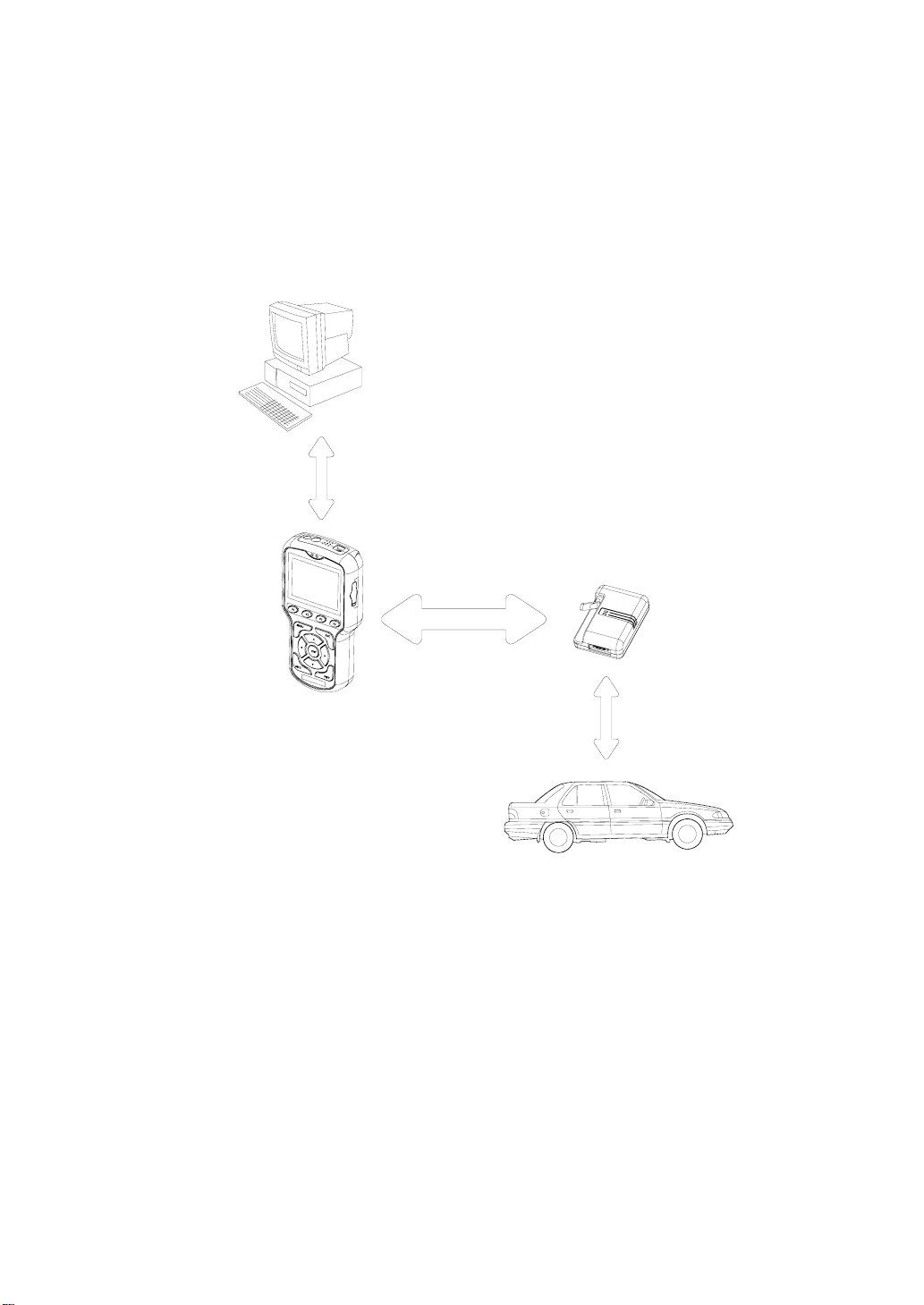
I. OUTLINE
USB
12Mbps
2.4G Hz Wireless
Communication
Wireless
Modu le
Wireless
Autom otive
Scanner
Diagn ostic
Communication
[Picture I-1. Outline]
Page 8
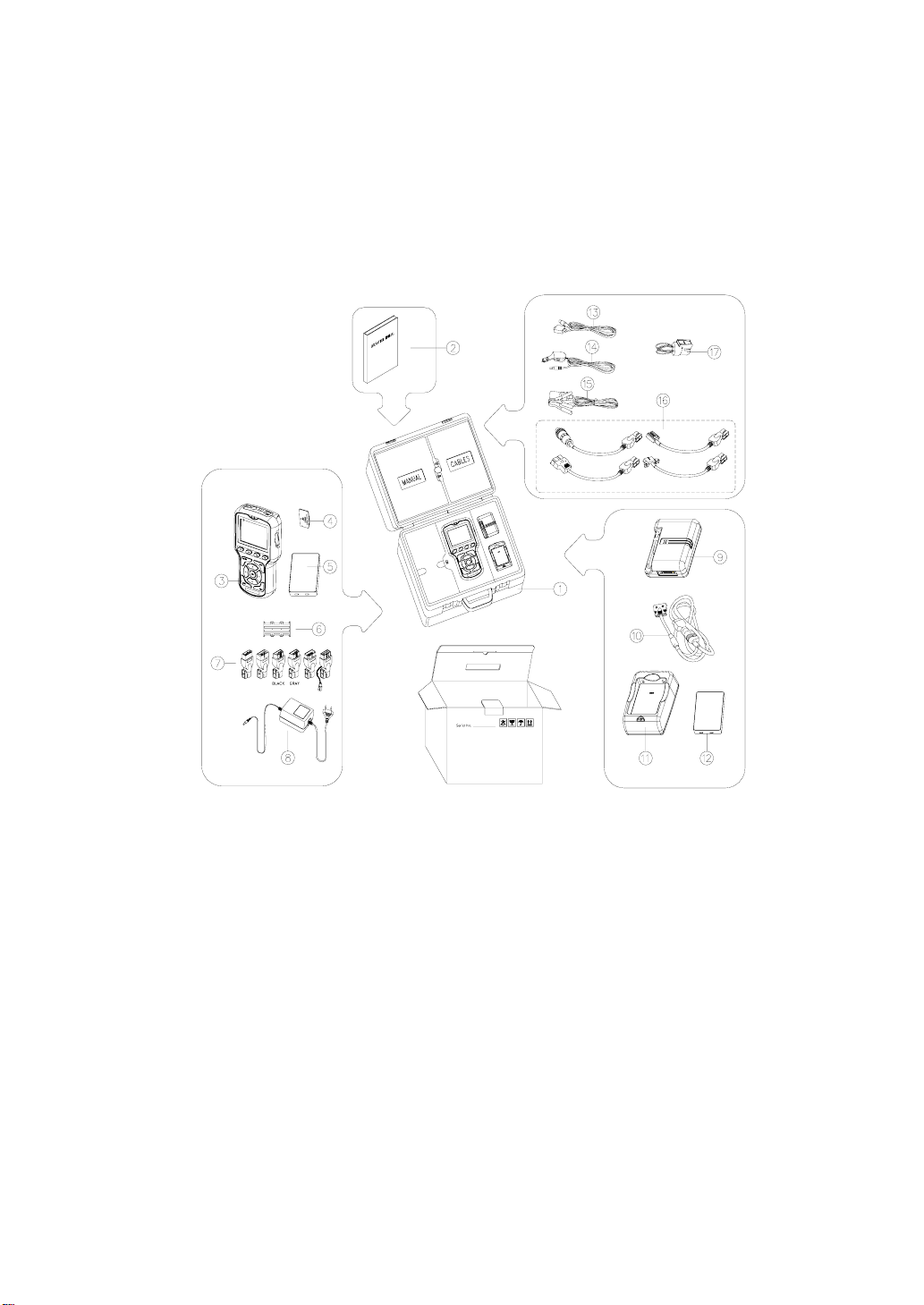
1. COMPONENTS
4
F
3
F
2
F
1
F
C
S
E
U
N
E
M
▲
▶
T
N
E
◀
▼
R
W
P
G
A
I
D
[Picture I-2. Components]
Page 9

1.1 Components Table
NO Component Name Component No.
1 Bag 068-M3012
2 Operating Manual MJJ-CR6-E0001
3 Main Body 068-E0001
4 Program Card (built into the main body) JXD-128
5 Rechargeable Battery (main) JBT-01
6 Program Card Case -
OBD-II 16P Adaptor CB-96-0063
GM Daewoo 12P Adaptor CB-96-0061
Ssangyong OBD-II 16P Adaptor CB-96-0063S
Kia 20P Adaptor CB-96-0064
Kia 6P Adaptor CB-96-0066
7
Renault Samsung/Nissan 14P Adaptor CB-97-0046
Proton OBD-II 16P Adaptor CB-96-0063P
HONDA 3P Adaptor 068-M1002
BMW 20P Adaptor 068-M1003
Toyota Rectangle-17P Adaptor 068-M1004
8 AC/DC Power Adaptor JAD-12V
9 Wireless Diagnostic Module 068-E0002
10 Main Cable 068-M1001
11 Battery Charger 068-E0003
12 (back-up)Rechargeable Battery(Optional) JBT-01
13 USB Communication Cable USB-AB-2M
14 Cigar Lighter Cable CB-96-0069-02
15 Battery Cable CB-96-0069-01
Ssangyong 14P Adaptor 015-M1002-C
Ssangyong 20P Adaptor 015-M1001-C
16
Hyundai 12P Adaptor CB-96-0065
Benz 3P Adaptor 068-M1005
17 Self Test Adaptor 068-M1006
Page 10
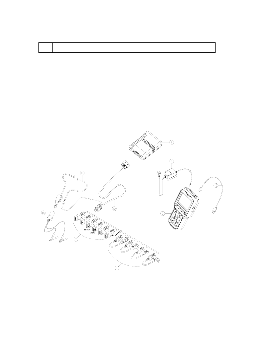
18 Benz 38P Adaptor(Optional) 068-E0004
※ Diagnostic adaptors and cables of No. 7 and 16 may vary depending
on product type.
1. 2 Connection System
[Picture I-3. Car-Doctor System]
Page 11

2. FEATURES AND FUNCTIONS
2.1 Features
1) Wireless Communication System
Through the high-speed data transmission function and the application of highly stable
wireless system, the Car-Doctor can diagnose a car in close range while moving.
2) 32-BIT High-performance CPU
The 32-BIT high-speed CPU enables faster and more accurate processing of data, and to
have various itemized data that are helpful in identifying source in def ects diagnosis.
3) Top-notch and highly stable Linux OS
The embedded Linux system effectively and stably manages the sys tem and hardware,
software, database, and diagnostic data.
4) Database OS
Efficiency, stability, and security are guaranteed by building the DB on car type and
diagnostic data, and the data on a new car can easily be upgraded.
5) Powerful Graphic Function
You can easily spot changes in diagnost ic data through the line and bar graphs made by
analyzing the diagnostic data.
6) USB Upgrade Function
Easy and high-speed upgrade on a new car is made possible by connecting to a
computer through USB.
7) CAN Communication Support
The case is an all-in-one type that combines strong ABS ma terial insid e and uretha ne on
its exterior to absorb and withstand shock and this strong and luxurious cas e was made
by applying the latest dual-injection molding technology.
8) Noblesse Case
The case is an all-in-one type that combines strong ABS ma terial insid e and uretha ne on
its exterior to absorb and withstand shock and this strong and luxurious cas e was made
by applying the latest double-injection molding technology.
9) User-friendly Design
Page 12

Handy-type design, high-resolution and easy-to-use LCD that is small and light, with
soft-touch key pad and large buttons for easy usage.
2.2 Function
1) MAIN MENU: Car Diagnosis Checkup Function
z Defect Diagnosis and Data Check
Engine, automatic transmission, ABS, airbag, suspension, traxion, air-conditioner
z Removal of Defects
z Data Analysis and Storage
Graph Function (Line/Bar Graph)
2) SYSTEM MENU: Setup and Self-diagnosis Function
z Screen Adjustment z Time Setting
z Sound (buzzer) setting z LCD TEST
z Battery Capacity z Memory Capacity
z RF TEST z System Information
※ RF TEST: check the communication b etween the wireless diagnostic module and
main cable.
3) SNAP-SHOT Analysis
Analyzes the stored data
4) Database Update Function
When diagnostic software for new car is added
5) Firmware Update Function
Adds or complements functions
3. SPECIFICATION
Page 13

3.1 Main Body
Case
Display
Key Pad
Main CPU
Dark gray and blue, Dual injection
Interior: ABS material; Exterior : Ur ethane
Monochrome graphic LCD (Resolution: 320 × 240)
Power LED (Red/Green), Communication LED (Red/Green )
Material: Rubber
Function Keys: 4; Operation Keys: 4; Direction Keys: 4;
Power Key: 1
32-Bit High Performance CPU
Main Clock: 200 MHz (Max. 266 MHz)
OS
Program Card
Wireless
Communication
PC
Communication
Rechargeable
Battery
External Power
Power
Consumption
Size [mm]
Embedded Linux 2.4
Type: Flash Memory Card
Basic 128 MB (can be expanded up to 256/512 MB)
Frequency : sharing 2.4-GHz frequency band
Speed : 125 K–1 Mbps
Ultra-sensitive Built-in Antenn a
USB 1.1 Full Speed (12 Mbps)
RS-232 Communication (service functions including A/S)
Runtime : over three consecutive hours (when completely
charged)
Recharge Time: within two hours
Final Charge Voltage: 8.0–8.4 [V] , 1700 [mAH]
DC 11 ~ 30 V Input
Below 4 W (But, Max. 9.4 W in charging)
Width: 120 Length: 225 Thickness: 47
Weight: 645 [g] (with battery: 115 [g])
Page 14
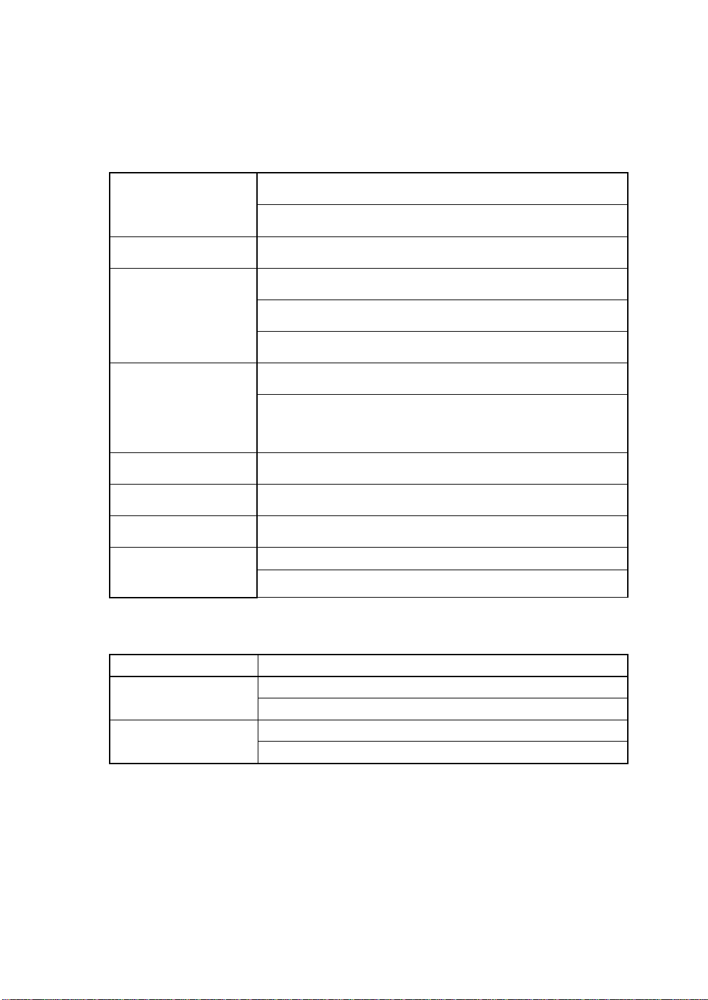
3.2 Wireless Diagnostic Module
Dark gray and blue, Dual injection
Case
Interior: ABS material; Exterior : Ur ethane
Display
Wireless
Communication
Power LED (Red/Green), Communication LED (Red/Green )
Frequency : sharing 2.4-GHz frequency band
Speed: 125 K–1 Mbps
Ultra-sensitive Built-in Antenna , 90˚ rotation
26 PIN Input/Output Terminal (power input, communication
input/output )
Vehicle
Communication
Operating
Temperature
Input Power
Power Consumption
Supporting all the vehicle interfaces including NRZ, UART, RS232C, CAN, PWM, VPWM, CLOCK, and PULSE.
0℃ – 50℃
Inputting DC 9 ~ 30V of vehicle battery power
Below 3W
Width: 82 Length: 117 Thickness: 36
Size [mm]
Weight : 222 [g]
3.3 Environmental Features
Condition Feature
Temperature
Relative Humidity
Operating Temperature: 0 to 50℃ (32 to 104℉)
Storage Temperature: –40 to 70℃ (–40 to 158℉)
Operating Humidity: 15% to 95% at 40℃
Storage Humidity: 90% at 65℃
Page 15
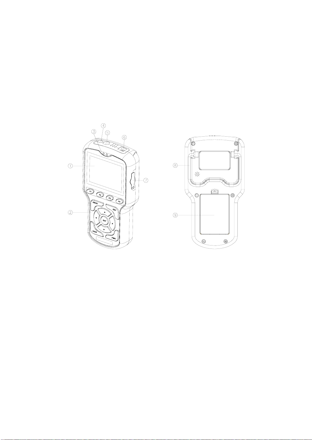
4. Main Body
4.1 External Shape
① LCD Screen
② Key Pad
③Status LED Display
Power Connector
④
⑤ RS-232 Port
⑥ USB Port
⑦ Program Card Slot
[Picture I-4. External Shape]
⑧Main Body Support
Rechargeable Battery
⑨
Page 16
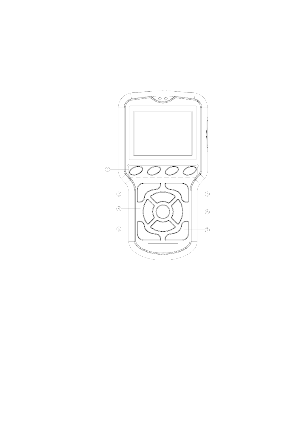
4.2 Key Pad Components
F1 F2 F3 F4
MENU ES C
▲
ENT
◀▶
▼
PWRDIAG
① Function Key F1,F2,F3, F4
② MENU Key
③ ESC Key
4.3 Key Function
④ Direction Key W, X, S, T
⑤ ENTER Key ENT
⑥ Diagnosis Key DIAG
[Picture I-5. Key Pad]
⑦ Power Key PWR
Page 17

Component Function
Four function keys are located on right below the LCD screen.
Because the functions vary according to each mode, the
mechanic can select the desired item and display it a t eac h
mode.
Function Key
F1, F2, F3, F4
MENU Key
Function Key Operation for Car Diagnosis and Checkup
- F1 (Item Fixing): Fixing the ite m the cursor selected
- F2 (Item Cancel): Canceling the fixed item
- F3 (Line Graph): Display the item that the curser fixed with
line graph
- F4 (Bar Graph): Display the item that the curser fixed with
bar graph.
Basic Menu
MAIN - SYSTEM - PRINT - DOWNLOAD, etc
Press MENU to display the Selection screen.
Direction
ESC Key
Up/Down
Key
Left/Right
ENTER Key
ENT
Diagnosis Key
DIAG
Power Key
PWR
S T
W X
Close the current screen and exit.
Back to previous menu screen.
Move the cursor up or down on the selected screen.
Move the cursor to the left and right at the selected screen.
Used in page transfer in the screen where several page exist.
(◀: Page Up, ▶: Page Down)
Select the item when the cursor is located.
Transfer into the selected menu screen
Quick Diagnostic Function
Move to the car type menu that was recently diagnosed.
Turn the power on and off.
Press it for over 4 seconds, and the power will go off.
4.4 Status LED Display
Page 18
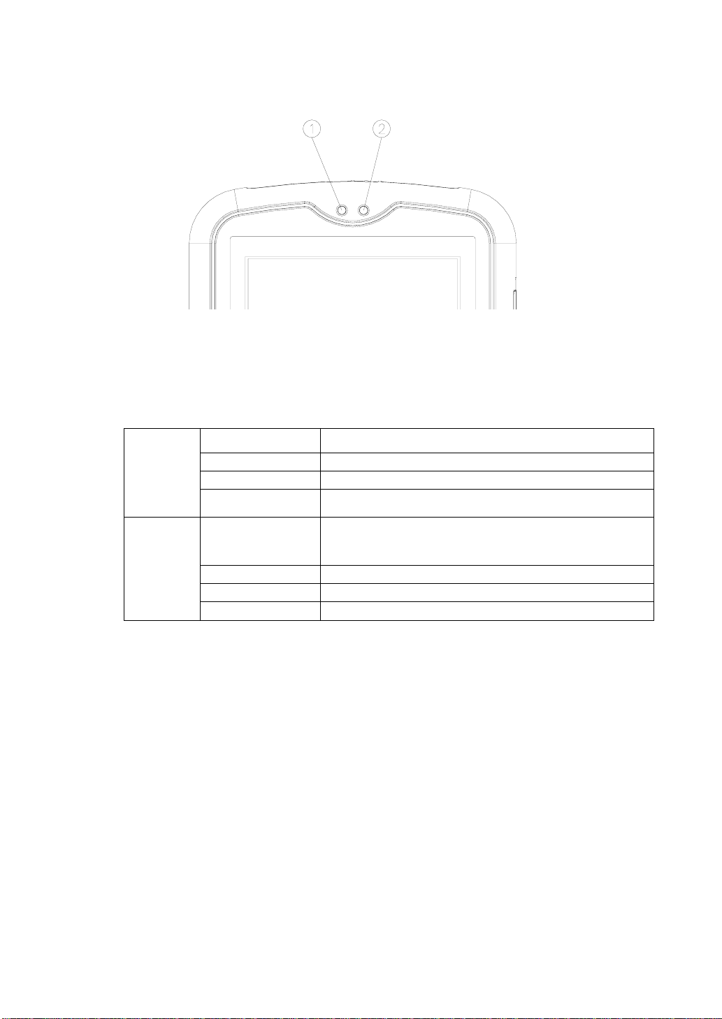
PWR COM
① PWR: Power LED ② COM: Communication LED
[Picture I-6. LED Display]
4.4.1 PWR LED: Upper Left
Displays the current status of power and battery
No Lighting Normal state
Power ON
Red Lighting Charging state
Green Lighting Indicates proper charging state
Yellow Lighting
Indicates the battery is fully charged (charging
completed)
Power OFF
Note: When the PWR LED blinks in red while in use, supply the power or replace the battery.
If not, battery discharge may occur and the device will lose power.
Red Blinking
Red Lighting In use
Green Lighting Indicates proper charging state
Yellow Lighting Indicat es full charging sta te
Indicates the need for charging and battery
replacement
4.4.2 COM LED: Upper Right
Display the current wireless communication status (Communication Status with
Wireless Module).
• Red Lighting: Data Transmission
• Green Lighting: Data Receipt
• In case wireless communication is in normal state in diagnosing a car, the red
and green lights at COM LED come out alternately, or yellow light comes out.
5. WIRELESS DIAGNOSTIC MODULE
Page 19
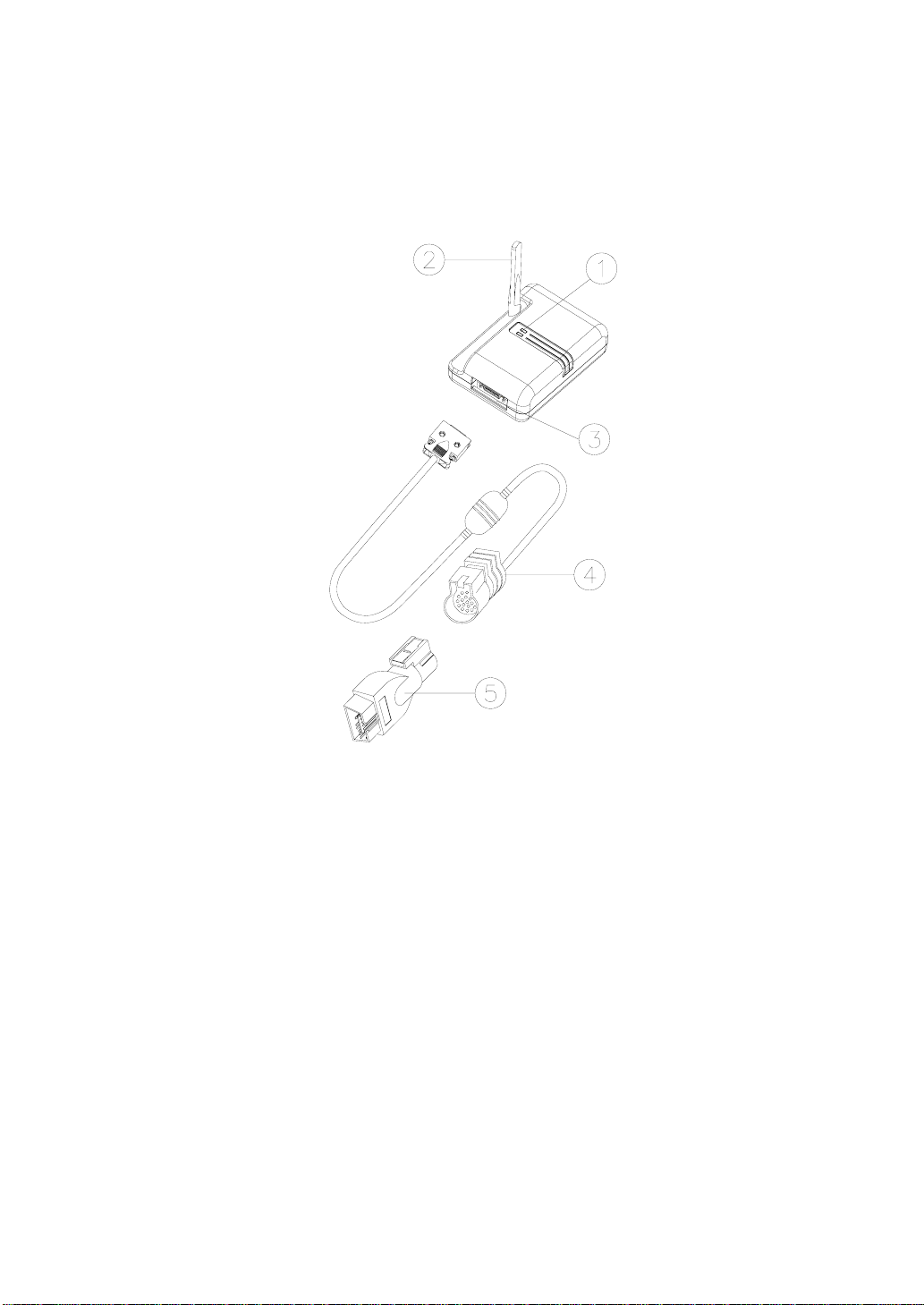
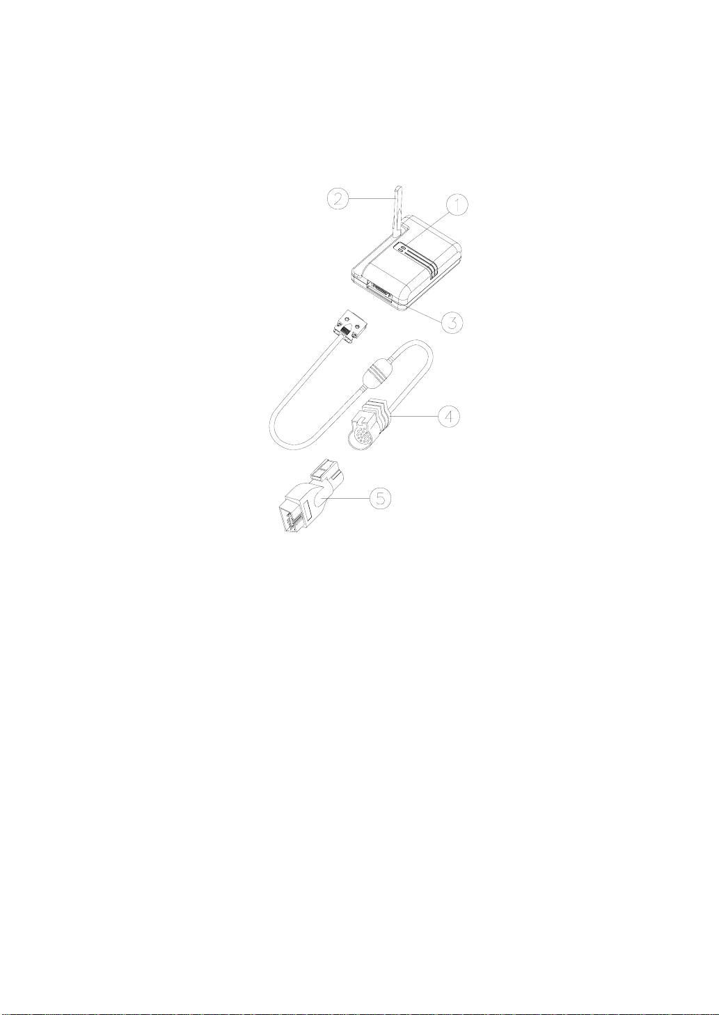
5.1 External Shape & Connection
① Status LED Display
② Antenna
Connection Sequence
① Connect main cable 26-pin connector to the main connector (put it to full until it is
clicked).
② Connect the car adaptor to the main cable 19-pin adaptor.
③ Set the antenna upright up to 90°
③ Main Connector (26 PIN)
④ Main Cable (26–19 PIN)
[Picture I-7. Wireless Module]
⑤ Car Adaptor
Page 20
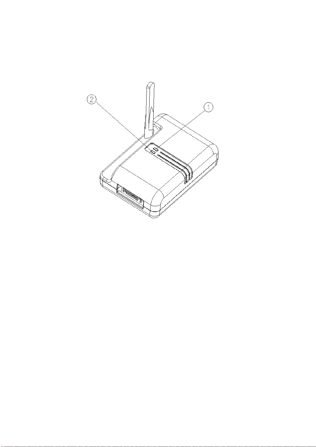
5.2 Status LED Display
① PWR: Power LED ② COM: Communication LED
[Picture I-8. Status LED Display]
5.2.1 PWR LED: Red LED
Display the current power state.
If the power is turned on, the red light comes on.
5.2.2 COM LED: Upper Right
Display the current vehicle communication status.(Communication Status between
Wireless Module and Vehicle)
• Red Lighting: Data Transmission
• Green Lighting: Data Receipt
• In case the communication with the vehicle is in normal state, the red and
green lights at COM LED come out alternately, or yellow light comes out.)
5.3 Vehicle Connection
Page 21
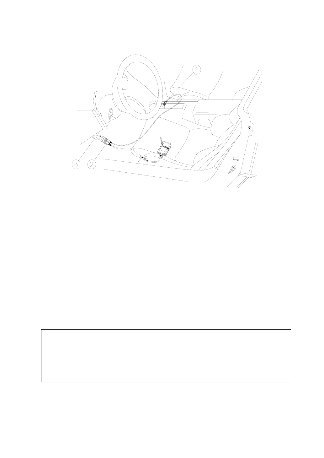
① Cigar Lighter Cable ② Main Cable ③ Car Adaptor
[Picture I-9. Vehicle Connection]
Picture 1-9 shows how to connect the Car-Doctor to the diagnostic connector
of the vehicle.
; Connect cable to the diagnostic connector of vehic le
; KEY-ON vehicle or start the vehicle
; If normally connected, PWR LED lights red
Note :
It is not needed to connect the cigar lighter cable in
diagnosing and checking the vehicle, because the vehicle
battery power is supplied to the wireless module. (
some vehicles, however, cigar lighter cable is needed to supply power).
For with
Page 22
5.4 Cigar Lighter Power Supply
① Main Cable ② Cigar Lighter Cable DC Jack
[Picture I-10. Cigar Lighter Power Connection]
The wireless module receives the battery power of the vehicle through the main
cable. However, power may not output through the diagnostic connector in some
vehicles. In this case, its power can be supplied by connecting the cigar lighter
cable.
6. COMPUTER CONNECTION
Page 23
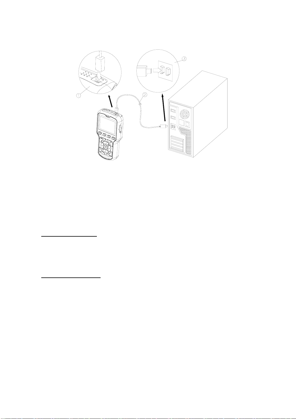
① USB-B Connector ② USB Cable ③ USB-A Connector
[Picture I-11. Computer Connection]
The Car-Doctor supports the communication with the computer with its expanded
function.
Connection Method
; Insert the B connector of the cable into the USB connector on the upper side of the main
body.
; Insert the A connector of the cable into the USB port of the computer
Connection Function
; Diagnosis data management and back-up (data upload & download)
; Diagnosis data output
; Vehicle DB update
; Diagnostic system firmware update
※ For further details, see the PC program manual.
7. AC/DC POWER ADAPTOR
Page 24
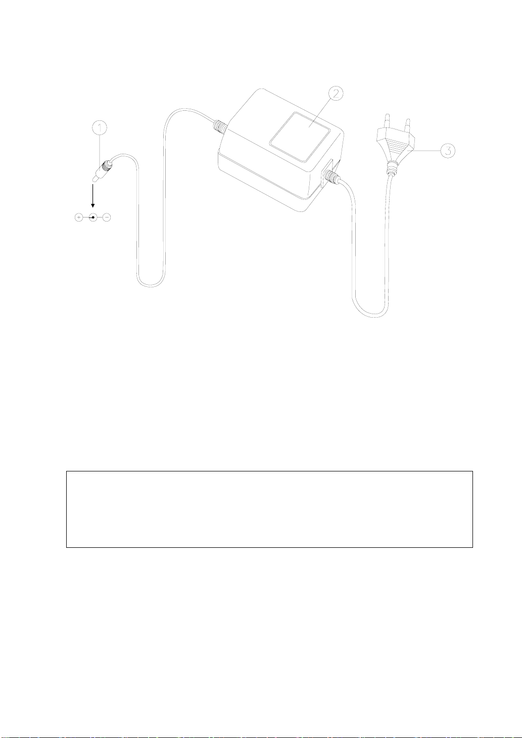
① Power Supply Jack ② AC/DC Power Adaptor ③ AC Power Plug
[Picture I-12. AC/DC Power Adaptor]
; AC/DC power adaptor is used for charging and external power supply.
; Input: AC 100–230V, 50/60Hz
; Output: DC 12V/1.2A
CAUTION!
Please use only the AC/DC power adaptor provided with the device. Unauthorized
products may seriously damage the equipment. We are not responsible for any defect
caused by using other products or power adaptors.
Page 25
8. RECHARGEABLE BATTERY
8.1 Insertion and Removal
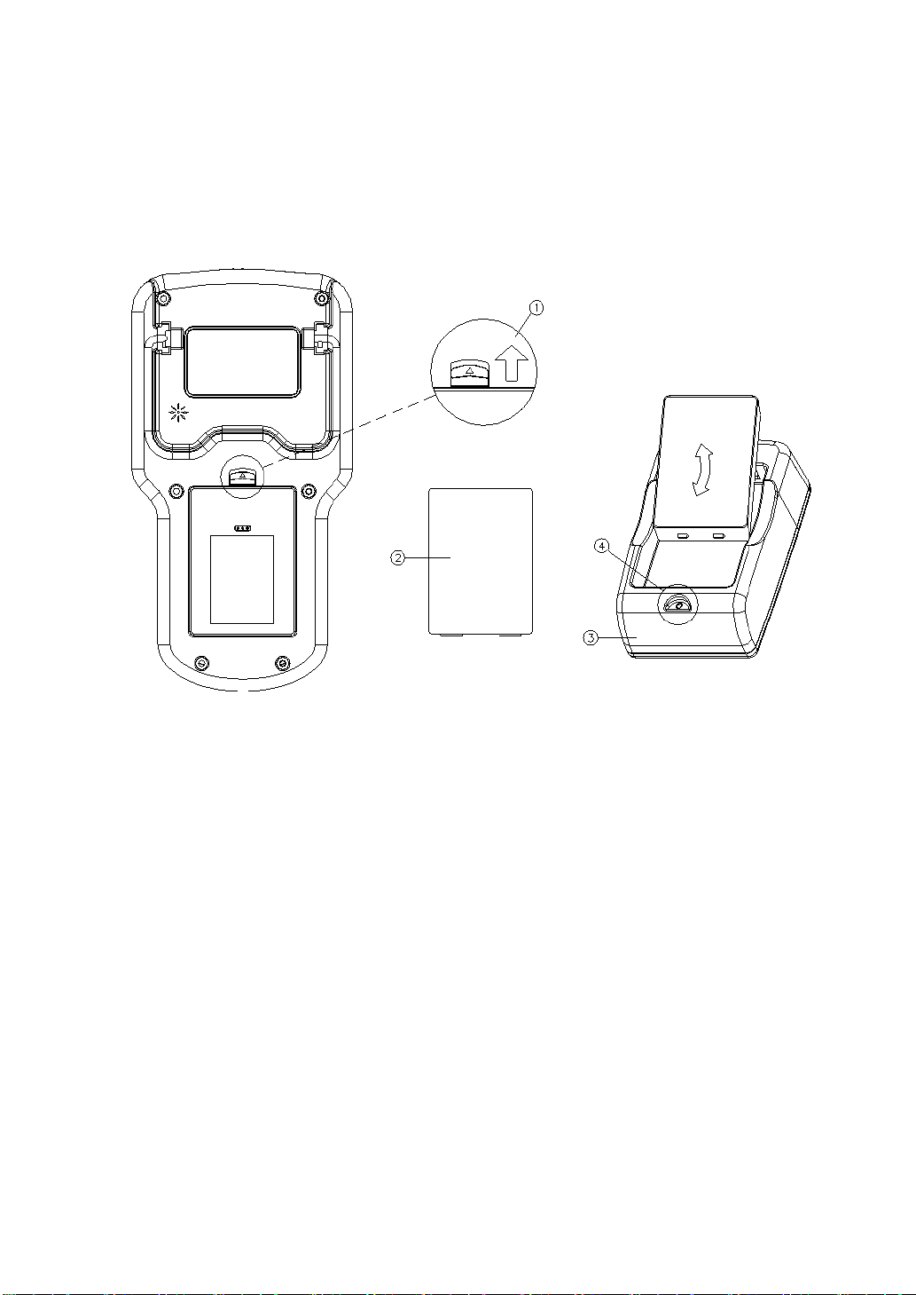
① Lock Lever
② Rechargeable Battery
[Picture I-13. Battery Insertion/Removal]
; Removal: Push up the lock lever on the back of the main body as seen in the
above picture, then slightly pull the upper part of the battery.
; Charging: Insert the battery as seen in the above picture to begin charging. In
case the insertion is properly done, the PWR LED turns on.
(Red, Green, or Yellow light comes on according to the charging
conditions.)
; Insertion: Insert the battery so that the main body and contact pin terminal of
the battery can be in contact with each other. Insert it by pressing inward
after the projecting part of the lower part of battery and the two grooves
on the lower battery insertion part of the main body have been in contact
③ Charger
④ PWR LED
Page 26
with each other.
Press the battery firmly until the lock lever clicks. If the battery is
not firmly in place and falls out, it may be damaged.
8.2 Charging
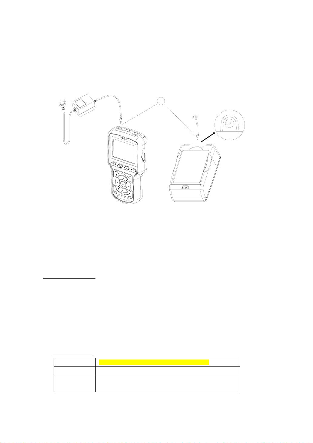
① AC/DC Power Adaptor DC Jack
[Picture I-14. Power Connection for Charging]
The Car-Doctor can be also charged in its main body. In addition, it can be
charged with the provided charger and back-up battery.
Charging Method
; Supply power by connecting AC/DC power adaptor.
; Charging is available while using the main body.
(For fast charging, please turn off the device while charging the battery)
; Checking the charging status through PWR LED is available.
; If necessary, battery charging can be done by battery charger.
PWR LED Status
No Lighting When AC/DC power adaptor is not connected
Red Lighting Currently charging
Green
Lighting
Proper charging state
Page 27

Yellow
Lighting
; If charging is completed, use the battery after pulling out AC/DC power adaptor.
Fully charged state (completed)
※ Both the main body and charger have a built-in protection circuit,
which prevents the battery from overheating due to excessive
charging (prevents from overheating and explosion).
8.3 Li-ion Rechargeable Battery
8.3.1 Specifications
Car-Doctor uses Li-ion rechargeable battery (The Li-ion battery is of good quality and its
expected lifespan is much longer than existing Ni-Cd or Ni-Mh batteries).
; Final Charge Voltage: 8.0–8.4 [V], 1700 [mAH]
; Recharging Time: Within two hours
; Runtime: Over four consecutive hours (when completely charged
8.3.2 Battery Charging
In case PWR LED blinks (repeats on and off), which indicates that battery capacity is
insufficient, please replace or recharge the battery.
8.3.3 Expected Life Span & Replacement Cycle
The more the Li-ion battery is used or recharged, the shorter is its lifespan. It is
recommended to check it periodically (once every six months) or to replace it (on ce a
year).
)
Page 28
9. PROGRAM CARD
9.1 Installation and Removal
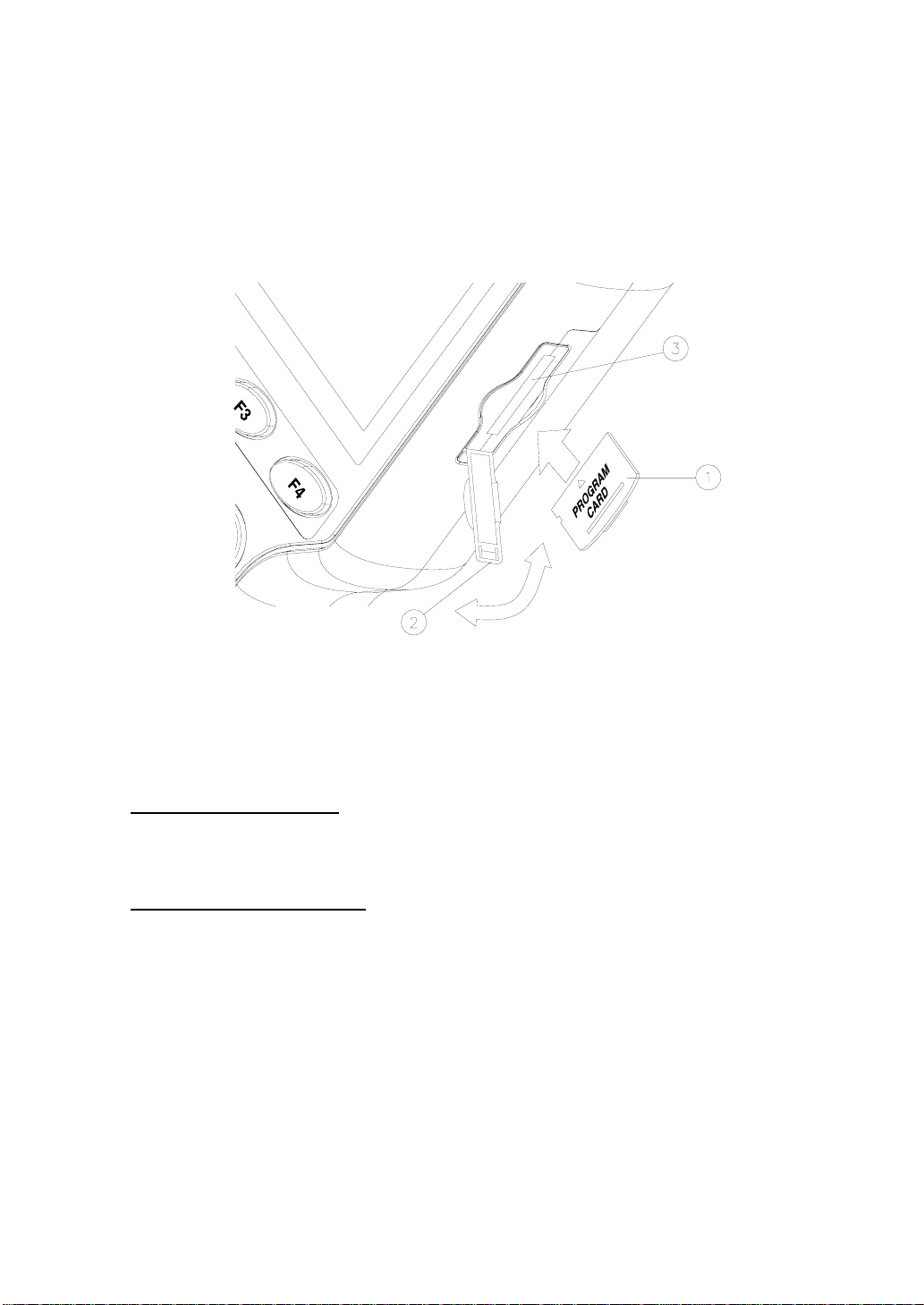
① Program Card ② Card Protection Cover ③ Card Connector
[Picture I-15. Program Card Installation]
Program Card Removal
; After turning off the power, open the card protection cover downwards and pull out the
end of the program card inserted in connector.
Program Card Installation
; Insert the program card in the connector as seen in the above picture.
; Turn on the power.
(Power Reset! In case the replacement was done when the power is on, turn off the
device and turn it on again. If the power is not rese t, the existing card program, not the
new program, is operated.)
Page 29

Note: Data Back-up
If there's stored data, transmit and save the data to the computer (by uploading
through USB), and replace the program card.
9.2 Program Card
The program card has built-in flash memory.
With the high capacity of basic 128 MB, one card is enough for the diagnosis and
data storage.
Power: 3 V (3.3 V)
Size (P x L x H): 20 mm x 25 mm x 1.7 mm
Weight: 2 g
Page 30
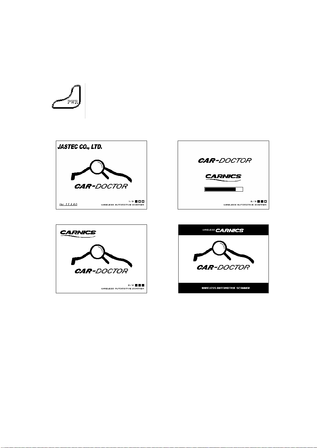
II. HOW TO USE
1. POWER ON/OFF
Press the power key on the lower left side to turn on the power
and boot up the Car-Doctor.
1.1 Booting
Turning on the device boots up the Car-Doctor.
Boot Screen Æ During boot up of the OS….
Æ During boot up of application…. Æ During boot up of database….
It takes approximately 50-60 seconds to complete the boot up.
Do not turn off or operate the Car-Doctor during boot up.
Page 31
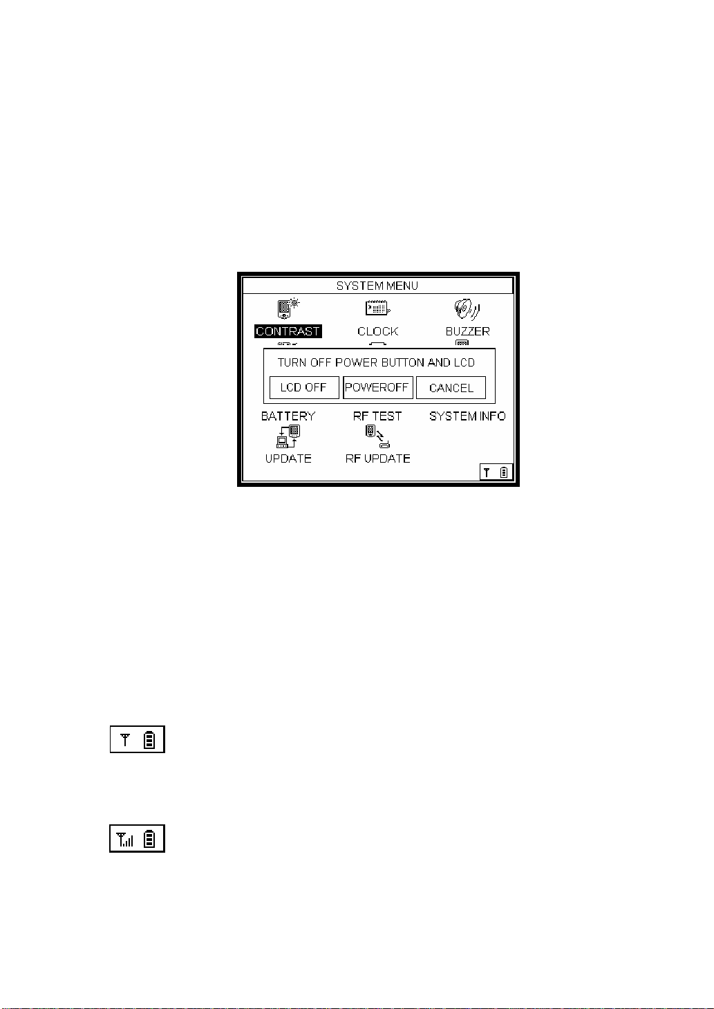
1.2 Power Off
Press the power key, and the screen as shown below will be displayed. Select
"POWER OFF" in the middle by pressing Left/Right (W / X) key to turn off the power.
Selecting “LCD OFF” turns off the LCD by the power-saving function. The powersaving function enables longer use of the Car-Doctor. If you want to use it again, just
press any key to turn on the LCD.
Picture 1 [Power Off Screen]
Note: Press the power key of the Car-Doctor for 4–5 seconds to force shutting off the
power. Please do this when the operation is abruptly stopped due to unknown
reasons or any defect caused by internal/external shocks, or noise.
1.3 Antenna & Remaining Battery Capacity
In the lower right side of the screen, the communication status and the remaining
battery capacity are displayed as shown below.
The left icon indicates the status of wireless communication. While the
vehicle diagnosis is being done, the antenna icon appears with full bars; otherwise,
when reception is poor, the antenna icon shows few or no bars at all.
The right icon indicates the remaining battery capacity. If the icon shows
only one block or none, the battery should be recharged.
Page 32
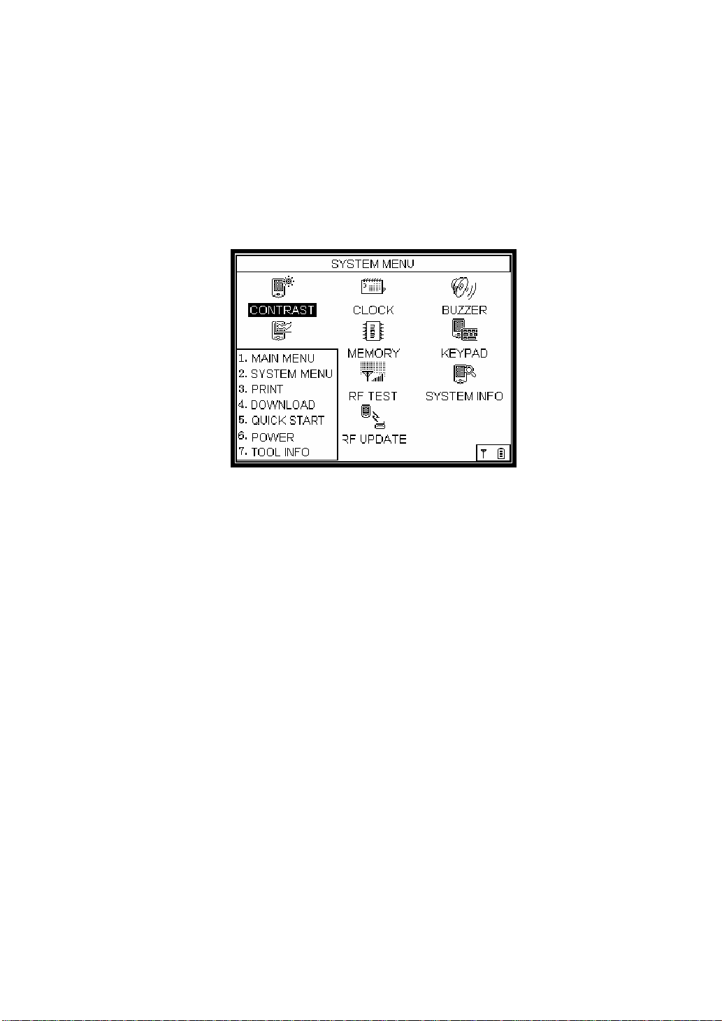
2. MENU
How to Select: Press the Menu key, and the menu item will pop up in a box on
the lower left.
Picture 2.1 [Menu Screen]
The menu item appears by pressing the MENU on the key pad.
This menu item includes:
1. MAIN MENU
2. SYSTEM MENU
3. PRINT
4. DOWNLOAD
5. QUICK START
6. POWER
7. TOOL INFO
By using this menu item, the user can shift to the diagnosis or system setup
screen. QUICK START is to instantly run user’s preset item. The following are the
details on each menu item.
Page 33
2.1 MAIN MENU
Select MAIN MENU.
Picture 2.2 [The screen after selecting Main Menu]
The MAIN MENU shows car makers that the user may choose corresponding to the
vehicle to diagnose. Press the Enter key () after selecting MAIN MENU to go to
the screen of car maker selection.
Page 34
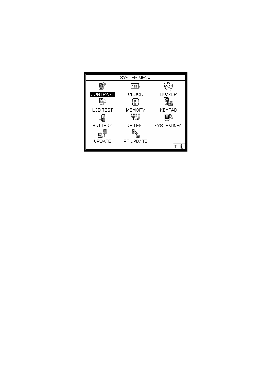
2.2. SYSTEM MENU
Select SYSTEM MENU.
Picture 2.3 [SYSTEM Setup Screen]
The system-related mode of the Car-Doctor gives the information on the
equipment of the main body and memory capacity. With this mode, one can
check and adjust settings for brightness/contrast, clock, battery info, LCD test,
buzzer, and RF test. It plays an important role in effective maintenance.
2.3 PRINT
Select PRINT.
This is the mode that allows the user to save the current screen on the LCD.
Select PRINT, then the current LCD screen will be saved as a picture file.
2.4 DOWNLOAD
Select DOWNLOAD.
This is to update software and transmit the screen capture file to the personal computer.
Page 35
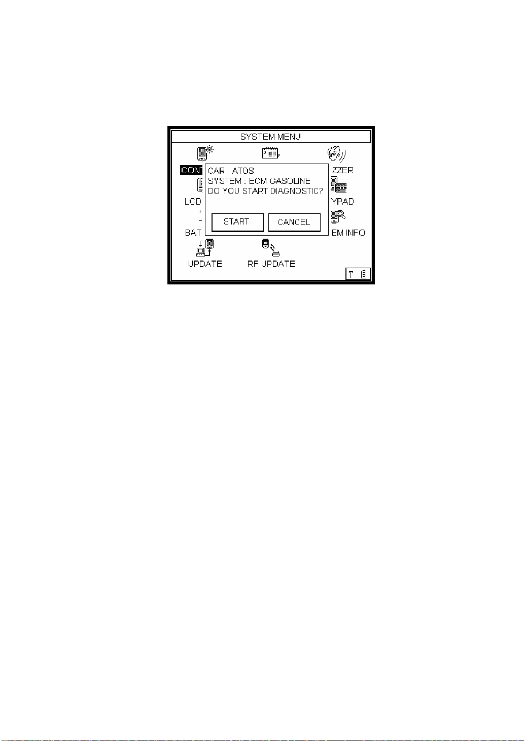
2.5 QUICK START
How to Select: Press the Menu key, and select QUICK START.
Picture 2.4 [The screen after selecting QUICK START]
QUICK START allows the user to save the item that was recently diagnosed. The
Car-Doctor should be used at least once to use QUICK START. The Car-Doctor saves
the last diagnosed item, and QUICK START enables to directly run the saved item.
The above picture shows the screen when QUICK START is selected.
Page 36
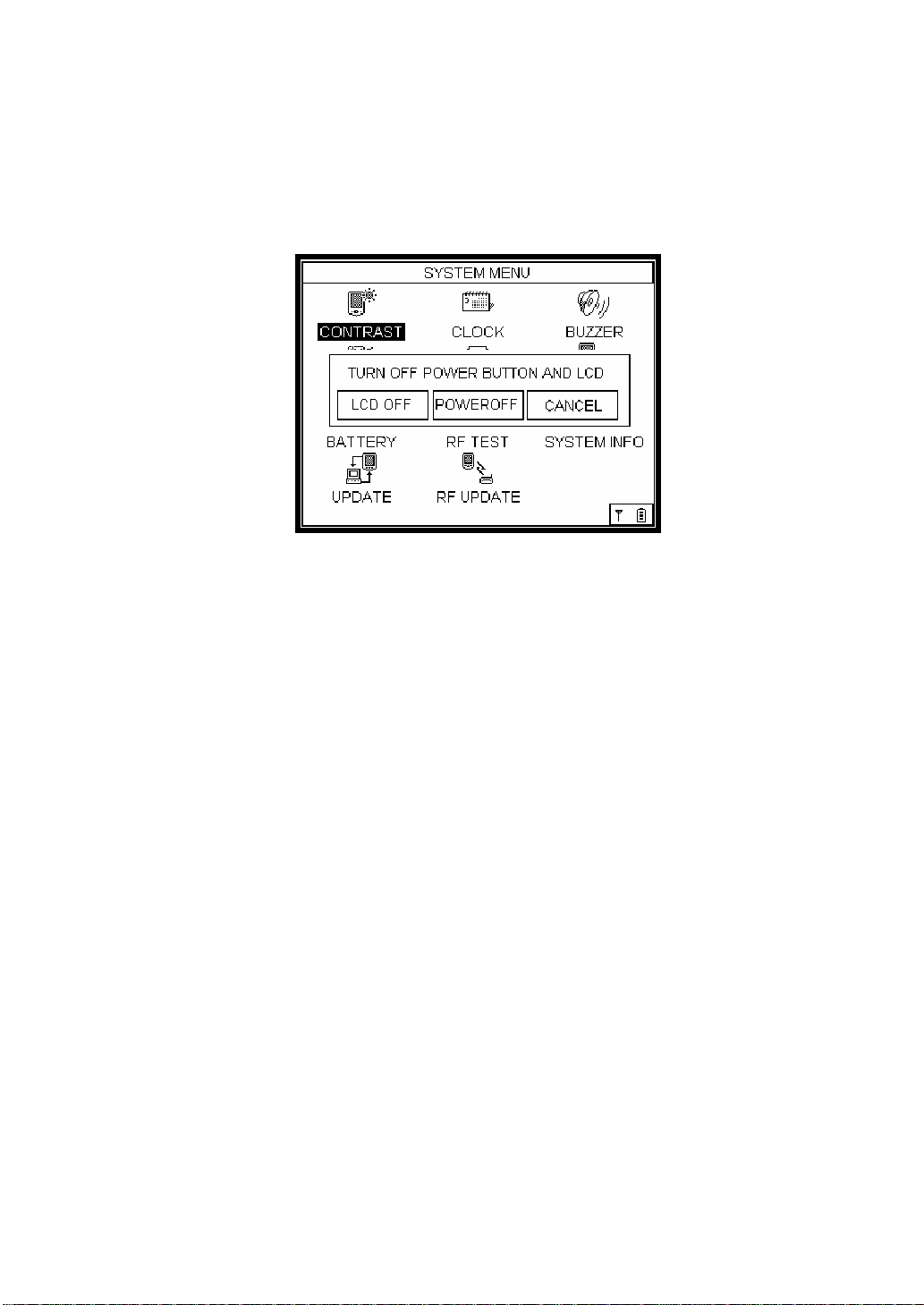
2.6 POWER
Select POWER.
Picture 2.5 [Power Key Screen]
By selecting POWER, it shows the LCD OFF, POWER OFF, and CANCEL items.
LCD turns off when chose LCD OFF menu. To switch on the LCD, just press the
Enter key (). To turn off the main body, select the POWER OFF Key.
Page 37
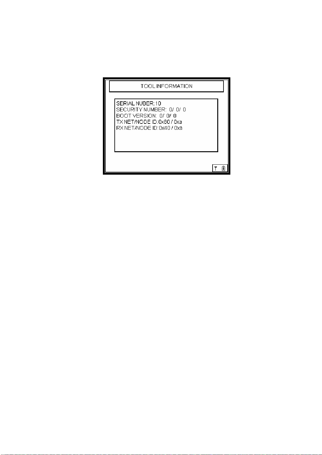
2.7 TOOL INFO.
How to Select: Press the Menu key, and select TOOL INFO.
Picture 2.6 [TOOL INFO screen]
The TOOL INFO displays the Car-Doctor-related information on equipment,
version, and DB, etc. This item can also be accessed by selecting the TOOL Info
icon on the SYSTEM MENU.
Page 38
3. MAIN MENU (DIAGNOSIS)
3.1 Car Selection
The following is the flowchart of Car-Doctor’s diagnosis. It is composed of car
maker selection menu, car selection menu, diagnosis item selection, and detailed
item selection.
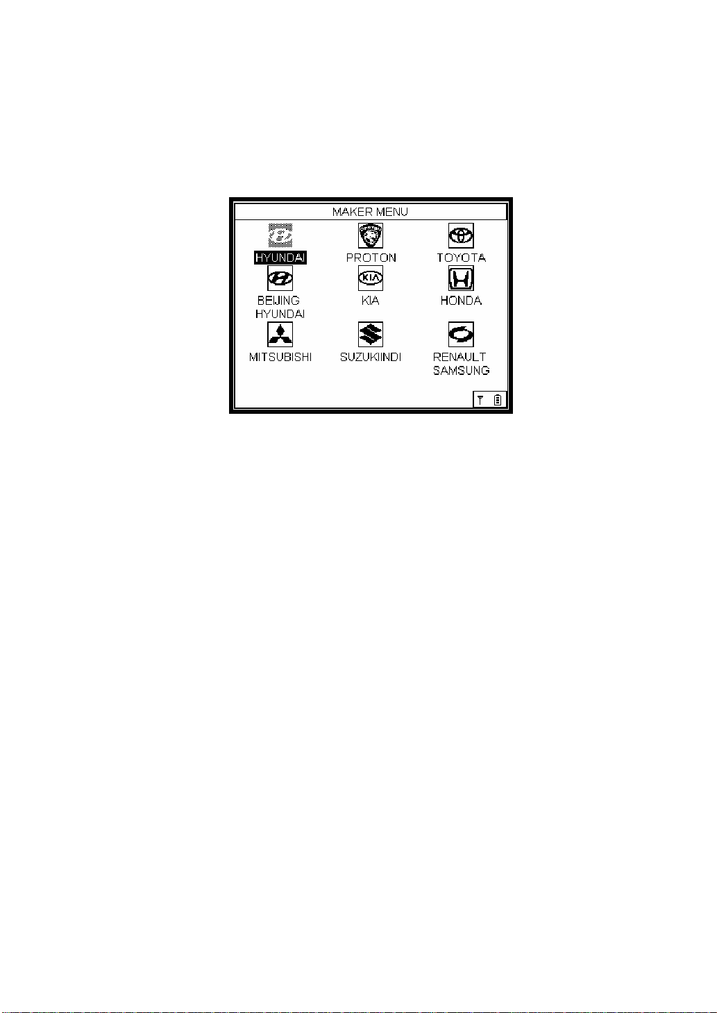
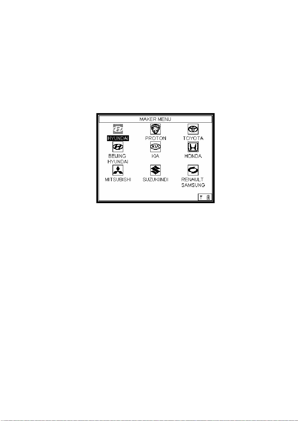
[Car Maker Selection]
Picture 3.1 [Maker Menu Screen]
When the user runs the Car-Doctor, the first screen that appears is the car
maker menu. In this screen, press Enter key () after selecting the maker of the
car the user wants to diagnose.
[TRANSFER] Select Car Maker (using the up/down and left/right arrows)
→ Press Enter key()
[NEXT] Car Selection
Page 39
[Car Selection]
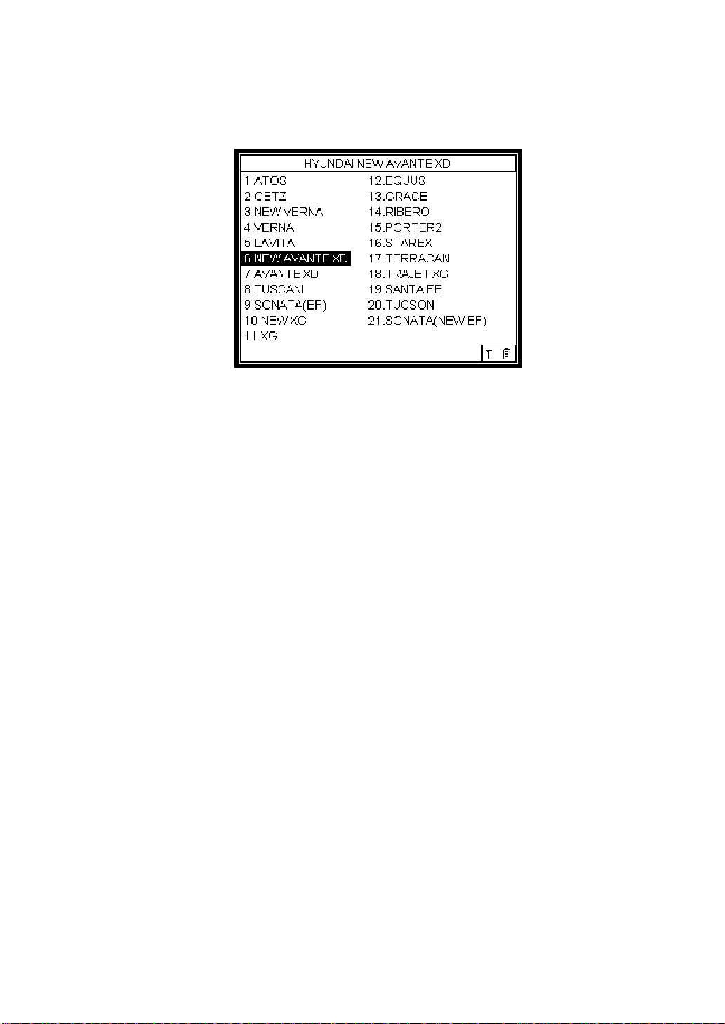
Picture 3.2 [Vehicle Selection Screen]
This screen displays the list of different car models under a particular car maker.
After selecting a car to be diagnosed, please press the Enter key (). The
diagnosable systems of the selected car will be displayed in the next screen
[TRANSFER] Select car model (using the up/down and left/right arrows)
→ Press Enter key ()
[NEXT: ] System Selection
[PREVIOUS: ESC] Car Maker Selection
Page 40
[System Selection]
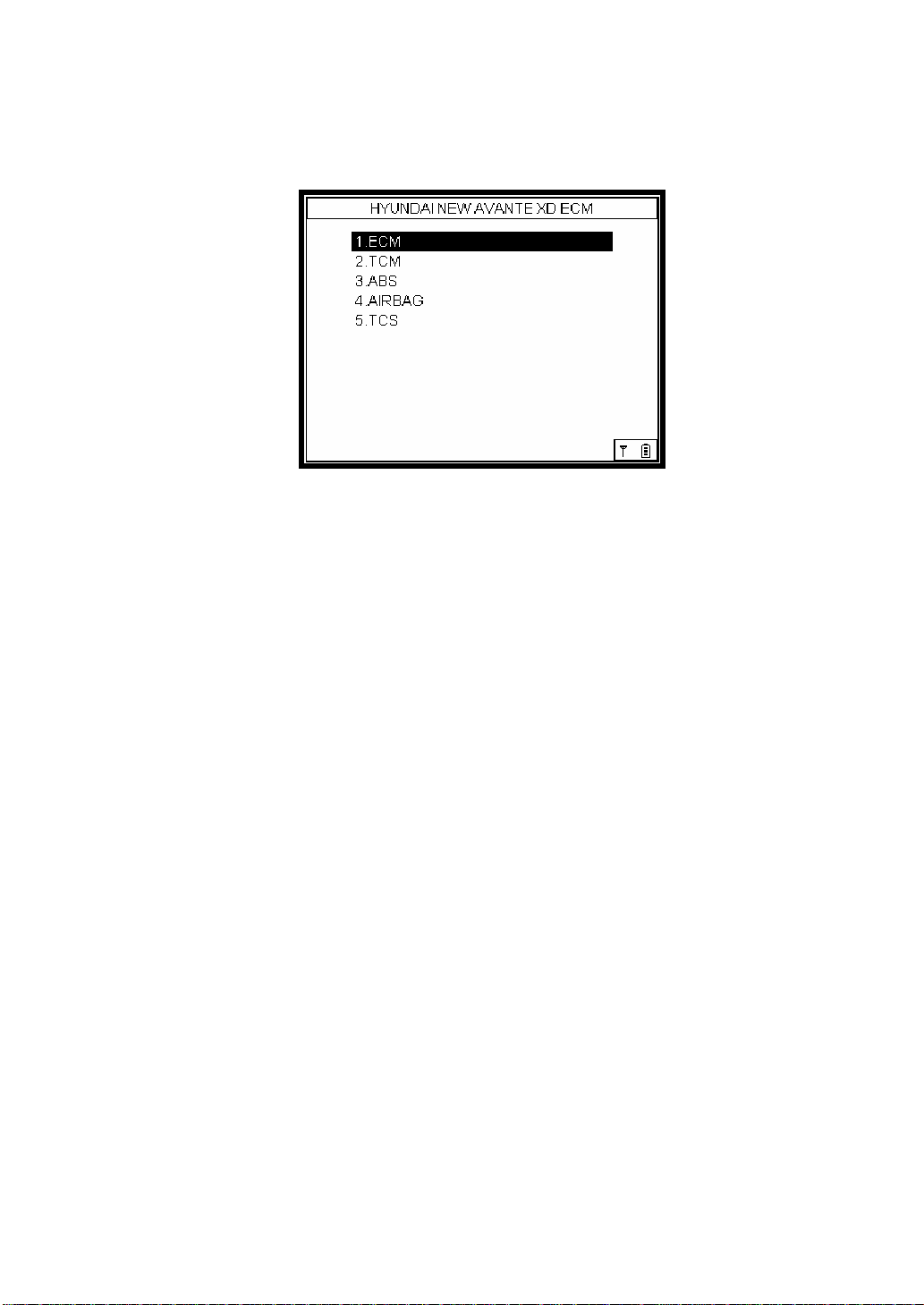
Picture 3.3 [Diagnosis Items]
The above screen lists the diagnosable systems of the selected car. Select the
system you want to diagnose, and press the Enter key ().
[TRANSFER] Select system (using the up/down and left/right arrows) →
Press Enter key ( )
[NEXT: ] Detailed Item Selection
[PREVIOUS: ESC] Car Selection
Page 41
[Detailed Item Selection]
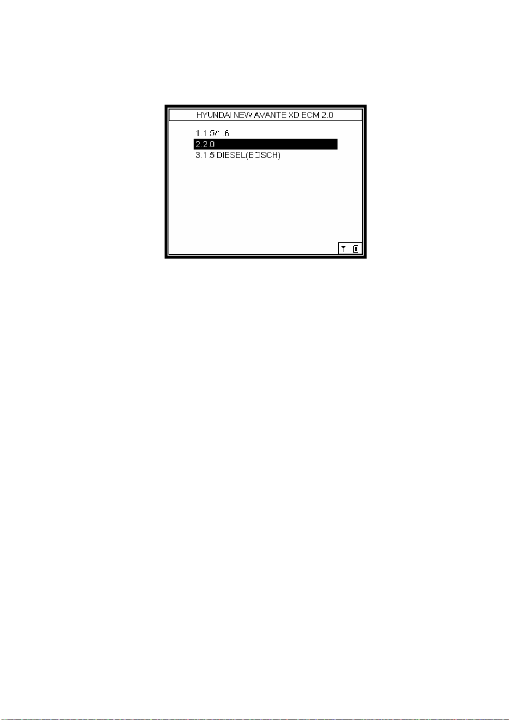
Picture 3.4 [Detailed Item Selection]
The above screen shows the detailed items of car. After selecting one of the
items to be diagnosed, please press the Enter key ().
[TRANSFER] Select item (using the up/down and left/right arrows) →
Press Enter key ()
[NEXT: ] Diagnosable Item Selection
[PREVIOUS: ESC] System Selection
Page 42
[Diagnosable Item Selection]
Picture 3.5 [Diagnosis Item on Engine Type 2.0]
The above screen shows the items that can be diagnosed.
[TRANSFER] Select item (using the up/down and left/right arrows) →
Press Enter key ()
[PREVIOUS: ESC] System Selection
Page 43
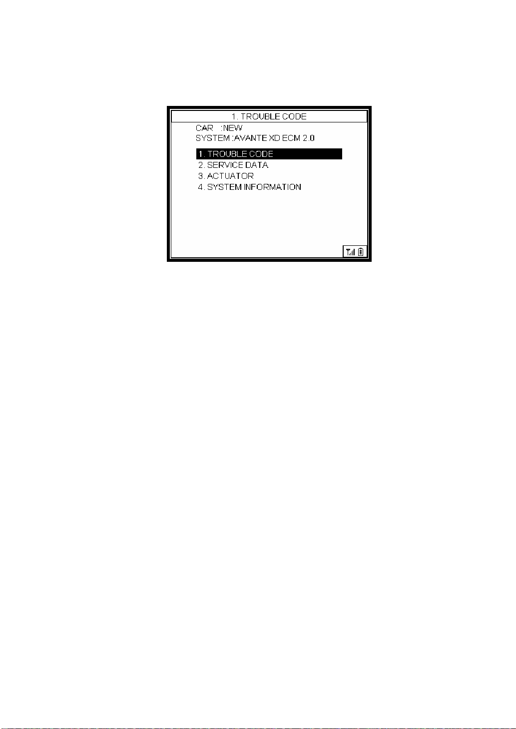
3.2 Self-Diagnosis
[Car Maker Selection] → [Car Selection] → [System Selection] →
[Detailed Item Selection] → [Diagnosable Item Selection] → [1. SelfDiagnosis Selection]
Selecting a detailed item in picture 3.4 displays the diagnosable items, as seen in
picture 3.5. Select Self-Diagnosis item among the diagnosable items.
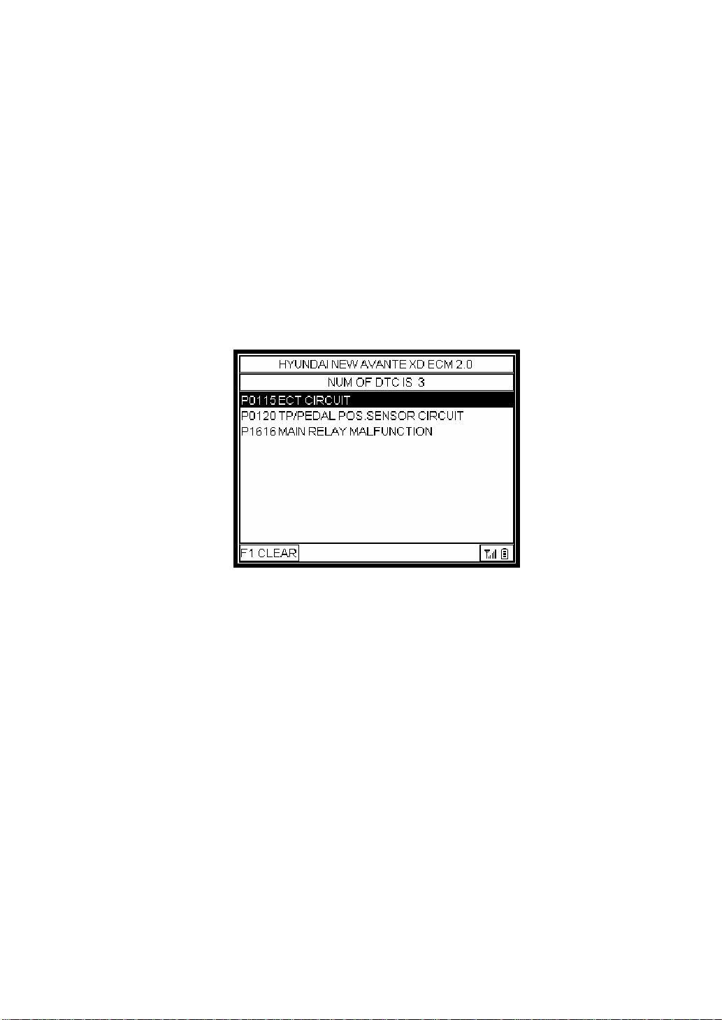
[Self-Diagnosis]
Picture 3.6 [Diagnosis Code Output Screen]
In case an error occurs with the selected ECM, the fault code is displayed in the
screen. To clear the fault code, press the F1 key.
※ Clear: The F1 key is used to clear the error code to be printed out after
diagnosis. Pressing F1 deletes the item.
Page 44
3.2 Service Data
[Car Maker Selection] → [Car Selection] → [System Selection]
→ [Detailed Item Selection] → [Diagnosable Item Selection] → [2.
Service Data Selection]
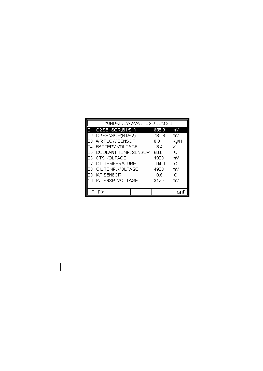
Selecting the detailed item in picture 3.4 shows the diagnosable items as seen in
picture 3.5. Select Service Data item among the diagnosable items.
[Service Data]
Picture 3.7 [Sensor Data Output Screen]
Picture 3.7 is the output screen on the service data. This item displays the data
of various kinds of sensors. Press F1 key to FIX the selected item.
Use S,T(up/down) to see the service data values, Using ◀, ▶ (left/right)
enables to access the next ten service data.
FIX
Press this key to fix the selected item. Although the user moves to the other
item using S, T key, the fixed item by FIX key is always at the same location.
It is useful to directly compare the data of fixed item and those of the other
specific items. (*) marks the fixed item, then press the FIX key (F1) again to
cancel.
Page 45
3.3 How to Use the Actuator Mode
[Car Maker Selection] → [Car Selection] → [System Selection]
→ [Detailed Item Selection] → [Diagnosable Item Selection] → [3.
Actuator Selection]
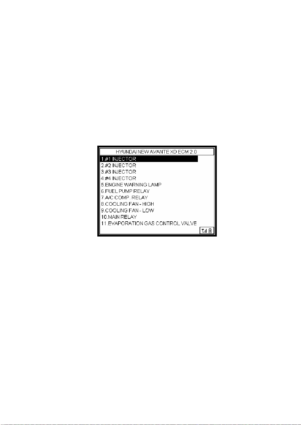
Selecting the detailed item in picture 3.4 shows the diagnosable items as seen in
picture 3.5. Select Actuator item among the diagnosable items.
Picture 3.8 [Actuator Items]
This is the mode to forcibly start and stop the actuator using the Car-Doctor.
Selecting the actuator function displays the actuator items that can be forcibly
started or stopped. Select the desired item, and press the Enter key ().
Page 46
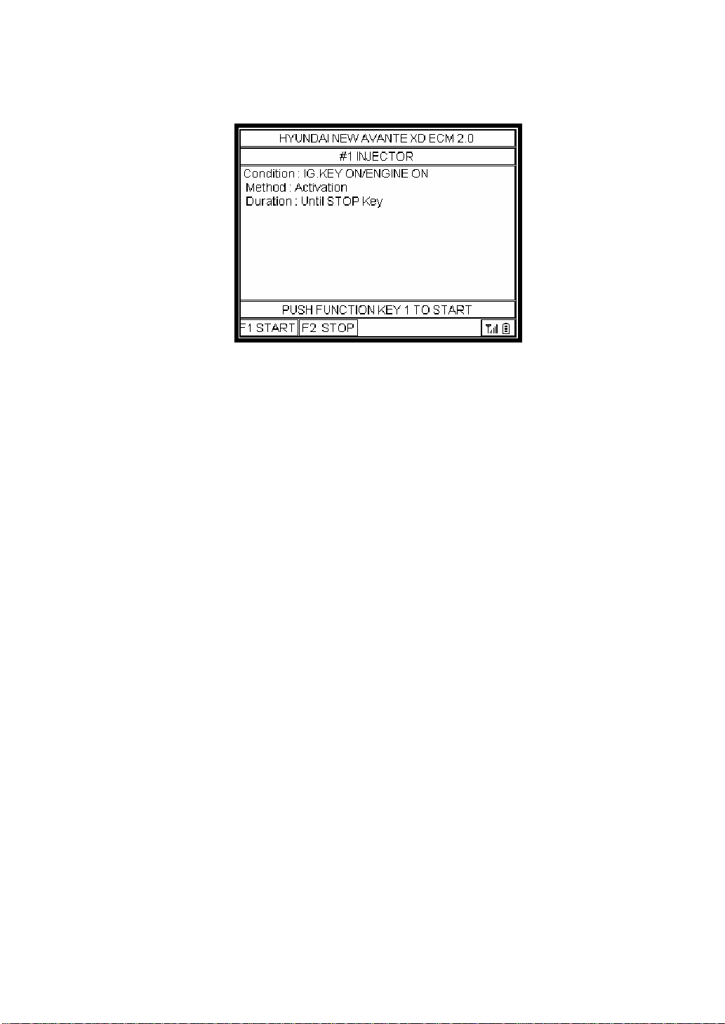
Picture 3.9 [Actuator Start/Stop]
Change the vehicle status into the status specified in the test conditions before the
actuator test. In case there’s test time, press the F1 START button, and the
actuator will be operated during the test time and will automatically stop. In case
there’s no test time, press the F1 START button to begin the test, and press F2
STOP to finish the test.
Page 47
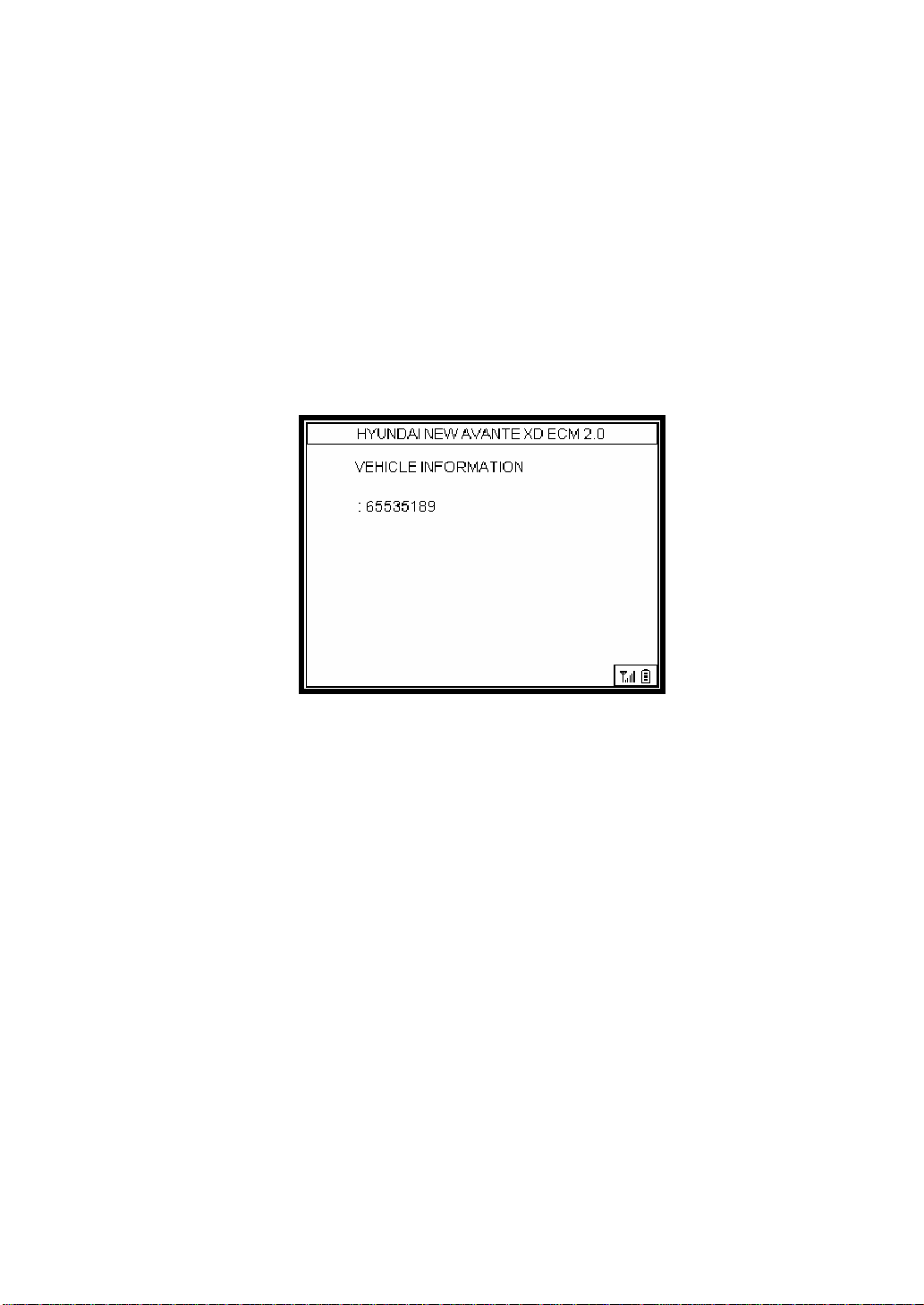
3.4 ECU ID Check
[Car Maker Selection] → [Car Selection] → [System Selection] →
[Detailed Item Selection] → [Diagnosable Item Selection] → [4. ECU ID
Check Selection]
Selecting the detailed item in picture 3.4 shows the diagnosable items as seen in
picture 3.5. Select ECU ID Check item among the diagnosable items.
Picture 3.10 [ECU ID]
Select ECU ID Check to see the information of the relevant ECU.
Page 48
4. SYSTEM MENU
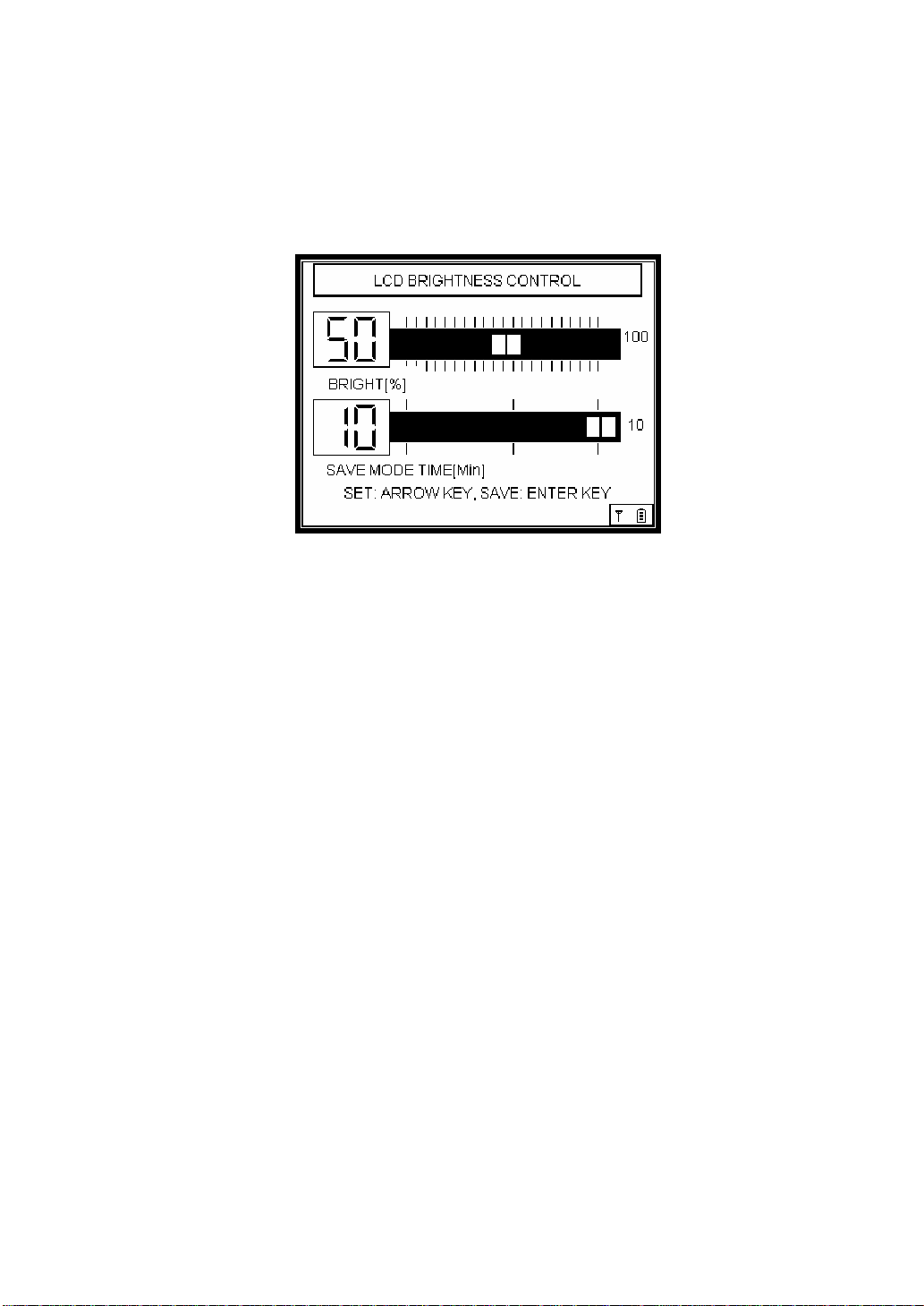
4.1 LCD Brightness Control & Save Mode Time Setting
Select contrast icon on the SYSTEM MENU.
Picture 4.1 [LCD Brightness Control Screen]
4.1.1 LCD Brightness Control
Follow the succeeding instructions to adjust the LCD brightness of the Car-
Doctor.
The direction keys W and X let the user adjust the LCD brightness.
Press W to decrease the screen’s brightness.
Press X to increase the screen’s brightness.
Note: Any drastic or sudden change in ambient temperature also changes the br ightness
of the LCD. If temperature dips below 0 ℃ or climbs over 40℃, the brightness should be
readjusted manually.
4.1.2 Save Mode Time Setting
Using direction keys S and T, the Save Mode Time can be adjusted. You can
set the save time from a minimum of 1 minute to a maximum of 10 minutes.
4.1.3 Saving
To save the newly set value, press the Enter key () (the message that saving
was done will be displayed). To return to the previous item, select the ESC key.
4.2 Clock Setting
Page 49
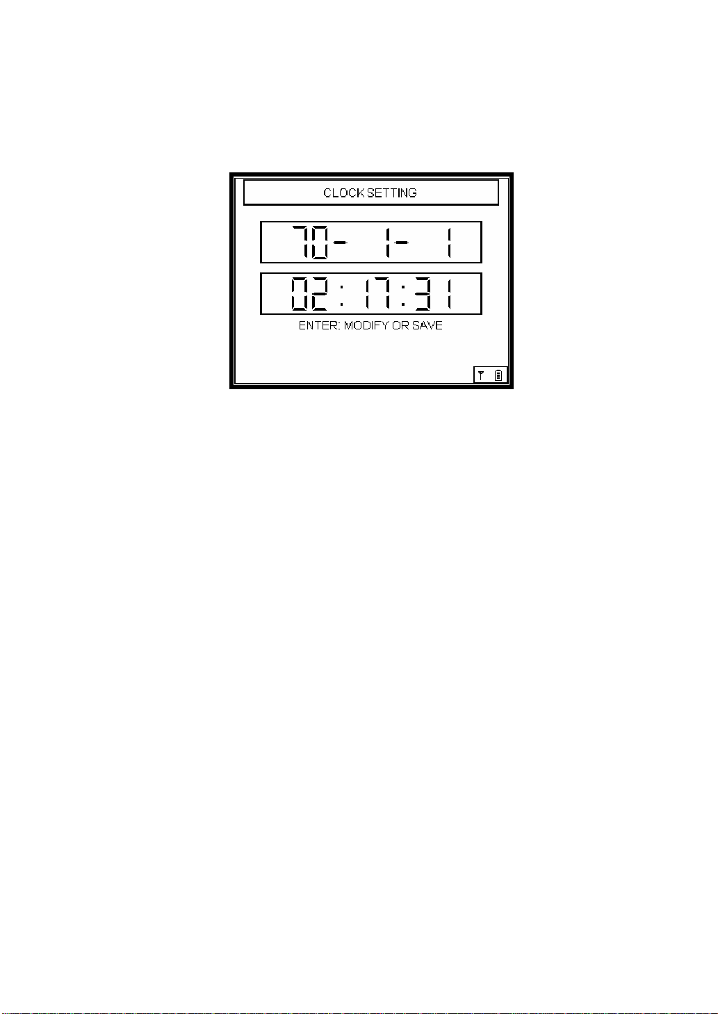
Select the clock icon on the SYSTEM MENU.
Picture 4.2 [Clock Setting Screen]
The time should be set the first time the Car-Doctor is used. Setting the time is
done as follows;
; Left/Right (W and X) Key: Allows the selection of year, month, day, hour,
minute, and second.
; Up/Down (S and T) Key: Can modify the value
① Pressing the Enter key () first, the Hour item will blink.
Use ② S and T to set the value of the blinking item.
③ Transfer to the next item using W and X to set the value of the next item.
When done④ , press the Enter key ( ) to save the settings.
(A message will appear to indicate saving is successful.)
⑤ To return to the previous item, select the ESC key.
Page 50
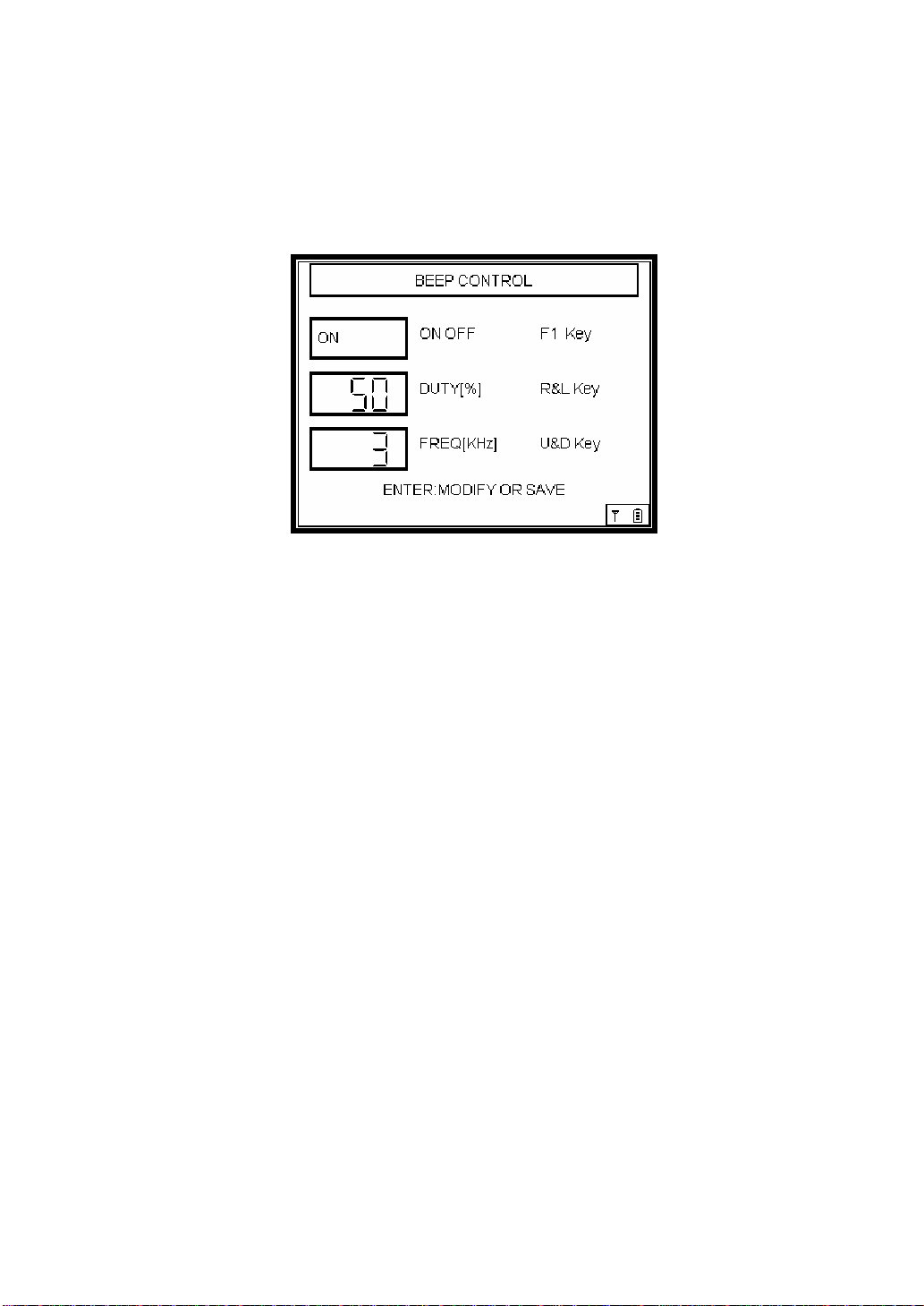
4.3 Buzzer Setting
Select the Buzzer icon on the SYSTEM MENU.
Picture 4.3 [Buzzer Setting Screen]
Car-Doctor can set the sounds when you press keys.
This is the way to set the buzzer.
; Left/Right (W, X) Key: Sets the volume of the buzzer.
(The bigger or smaller the number is, the stronger or weaker the sound is.)
; Up/Down (S, T) Key: Sets the pitch of the buzzer.
(The bigger or smaller the number is, the higher or lower the pitch is set.)
; Enter Key (): Saves the settings.
(A message will appear to indicate saving is successful.)
; ESC Key: Returns to the previous item.
Page 51

4.4 LCD TEST
Select the LCD Test icon on the SYSTEM MENU
Picture 4.4 [LCD TEST Screen]
The Car-Doctor can check whether the LCD has Dot Defect through the LCD Test.
As seen in picture 4.4, the screen is reversed every second, during which the user
must check for any pixel defect. To return to the previous item, select ESC key.
Note: Car-Doctor LCD consists of 320 ± 240 pixels.
Page 52
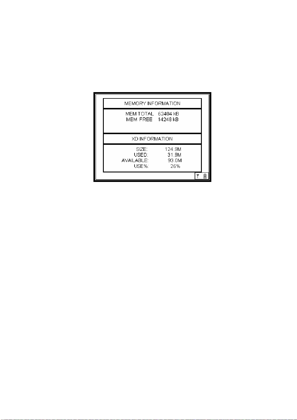
4.5 Memory Information
Select Memory icon on the SYSTEM MENU
Picture 4.5 [Memory Information Screen]
The Car-Doctor shows the internal memory capacity of the equipment, the
memory capacity, and the used capacity of the program card.
; Picture 4.5 shows the information on memory capacity and used capacity of
the equipment in the upper menu.
; The lower menu shows the information on the program card. The memory
capacity of the card, used capacity, and available capacity are indicated, and
the proportion of card use is indicated in percent.
; To return to the previous item, select ESC key.
Page 53
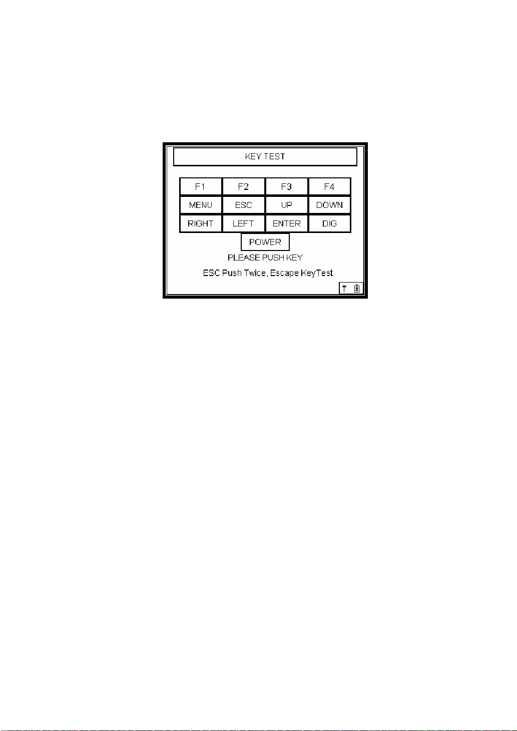
4.6 KEY TEST
Select KEY PAD icon on the SYSTEM MENU.
Picture 4.6 [KEY PAD Screen]
To check whether there’s any problem in keys, press any key. Then the key you
pressed will be reserved to check the problem.
; To return to the previous item, select the ESC key.
; To return to the System Menu after checking KEY PAD, press the ESC key
twice.
Page 54
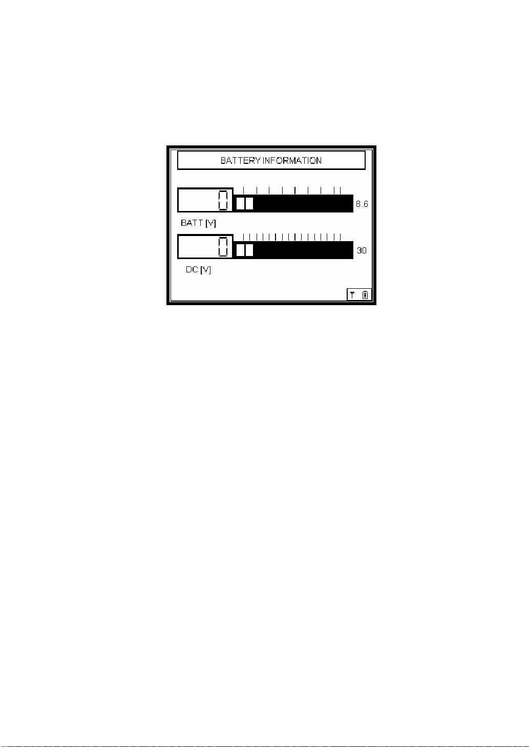
4.7 Battery Voltage Information
Select Battery icon on the SYSTEM MENU.
Picture 4.7 [Battery Voltage Info Screen]
; The upper graph indicates the current battery voltage.
In case the battery voltage is low, please recharge.
; The lower graph indicates the DC input voltage (external power).
; To return to the previous item, select the ESC key.
Page 55
4.8 RF-TEST
Select RF-TEST icon on the SYSTEM MENU to access the TEST screen.
The following shows the way to connect.
4.8.1 How to Connect
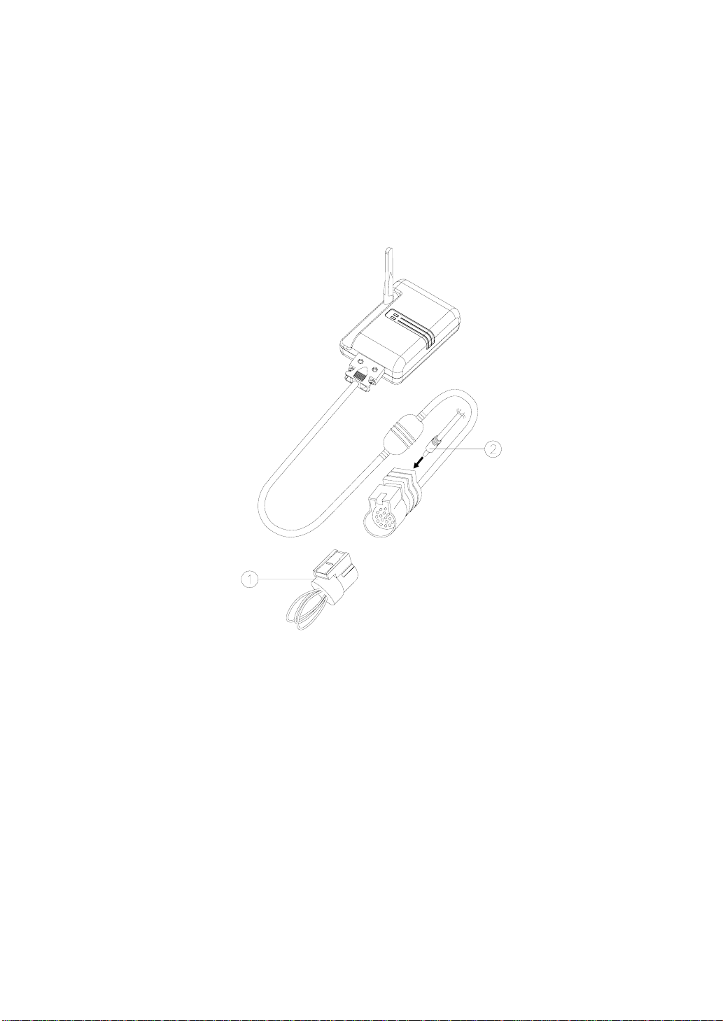
① Self-Test Adaptor AC/DC ② Power Adaptor DC Jack
[Picture 4.16 Self-Test Adaptor Connection]
① Connect the main cable and the Self-Test adaptor to the wireless module.
② Connect the AC/DC power adaptor DC Jack to supply power.
Page 56
4.8.2 RF TEST Screen
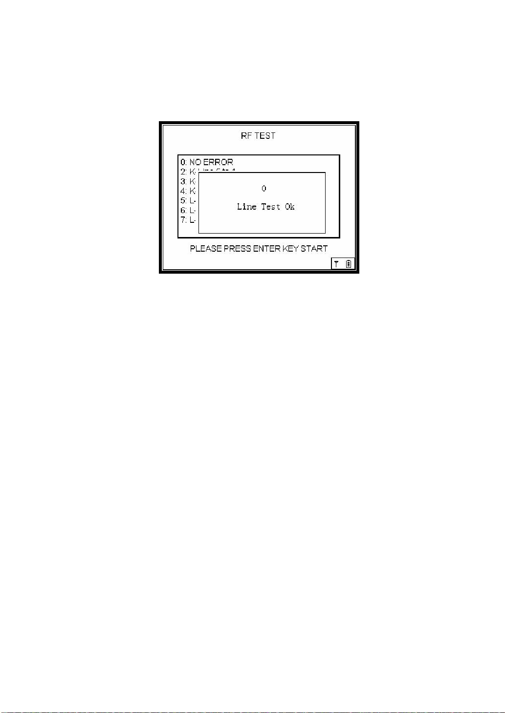
Picture 4.8 [TEST Screen]
RF Test checks the status of communication between the main body and the
wireless module, whether the wireless module has any defect or not. (Checking
the communication circuit of the wireless module)
① Press Enter key () to start the TEST.
② If any defect is detected, the relevant error message will be displayed.
③ To return to the previous item, select the ESC key.
Page 57

4.9 UPDATE
Select the Update icon on the SYSTEM MENU.
Update is used when Car-Doctor adds a new car or upgrades applications. It is also
used in updating the firmware of the wireless module.
For further details, see the provided manual.
4.10 Tool Information
Select the System Info icon on the SYSTEM MENU.
It is same with section 2.7 on Tool Info.
Page 58

III. APPENDIX
1. Types of Car Adaptors (Diagnostic Connector)…………………
2. PC Program (Dr. Sync) Operating Manual…………………………
Page 59

1. Types of Car Adaptors (Diagnostic Connectors)
SHAPE FUNCTION
OBD-II 16 Pin Adaptor
Enables diagnosis of vehicles
by connecting to the diagnostic
connector of OBD-II vehicle.
Daewoo 12 Pin Adaptor
Enables diagnosis of vehicles
by connecting to the 16 pin
diagnostic connector of the
general vehicles.
Ssangyong 20 Pin Adaptor
Enables diagnosis of vehicles
by connecting to the 20 pin
diagnostic connector of Musso
and Korando vehicles produced
after 1998.
Ssangyong 14 Pin Adaptor
PART NO.
CB-96-0063
CB-96-0061
015-M1001-C
Kia 20 Pin Adaptor
Kia 6 Pin Adaptor
Enables diagnosis of vehicles
by connecting to the 14 pin
diagnostic connector of general
vehicle types.
Enables diagnosis of vehicles
by connecting to the 20 pin
diagnostic connector of the
general vehicle types.
Enables diagnosis of vehicles
by connecting to the 6 pin
diagnostic connector of old
vehicle models.
015-M1002-C
CB-96-0064
CB-96-0066
Page 60

Samsung Adaptor (14 Pin)
Hyundai Adaptor (12 Pin)
Ssangyong OBD-II 16 Pin
Toyota R 17P
Enables diagnosis of vehicles
by connecting to the 14 pin
diagnostic connector of general
vehicle types.
Enables diagnosis of vehicles
by connecting to the 12 pin
diagnostic connector of general
vehicle types.
Enables diagnosis of vehicles
by connecting to the 16 pin
diagnostic connector of general
vehicle types.
Enables diagnosis of vehicles
by connecting to the square 17
pin diagnostic connector.
CB-97-0046
CB-96-0065
CB-96-0063S
068-M1004
Proton OBD-II 16P
Honda 3P
Enables diagnosis of vehicles
by connecting to the 16 pin
diagnostic connector of general
vehicle types.
Enables diagnosis of vehicles
by connecting to the 3 pin
diagnostic connector of general
vehicle types
CB-96-0063P
068-M1002
Page 61

Honda 3P
BMW 20P
Benz 3P
Benz 38P
Enables diagnosis of vehicles
by connecting to the 3 pin
diagnostic connector of general
vehicle types
Enables diagnosis of vehicles
by connecting to the 3 pin
diagnostic connector of general
vehicle types
Enables diagnosis of vehicles
by connecting to the 3 pin
diagnostic connector of general
vehicle types
Enables diagnosis of vehicles
by connecting to the 38 pin
diagnostic connector of general
vehicle types
068-M1002
068-M1003
068-M1005
068-E0004
※ Car adaptors may differ from the products described above depending on
the package you purchased.
Page 62

Operating Manual
1st Edition published in February
2006
Author: JASTEC CO., LTD.
Publisher: JASTEC CO., LTD.
Editing/Printing: JASTEC CO., LTD.
Registration No.:
Registration Date: February 2006
92-7, Geumgok-dong, Bundang,
Seongnam-si, Gyeonggi-do, South Korea
TEL: +82 31 719 5170, 2747 (DIRECT)
FAX: +82 31 719 5177
All rights reserved. No part of this book may be
reproduced or transmitted in any form without written
permission from the publisher.
 Loading...