

Jasic TIG 200 AC/DC Digital Series, TIG 315 AC/DC Digital Series, JT-200D, JT-315D Operator's Manual

wilkinsonstar.com
TIG 200 / 315 AC/DC
Digital Series
AC/DC MMA / TIG Welding machine
Order code ! JT-200D, JT-315D
OPERATOR MANUAL

Your new product
Thank you for selecting this Jasic Technology, Wilkinson Star product.
This product manual has been designed to ensure that you get the most from your new product. Please ensure that you are fully
conversant with the information provided paying particular attention to the safety precautions. The information will help protect
yourself and others against the potential hazards that you may come across.
Please ensure that you carry out daily and periodic maintenance checks to ensure years of reliable and trouble free operation.
Wilkinson Star Limited are a leading supplier of equipment in the UK and our products are supported by our extensive service
network. Call your distributor in the unlikely event of a problem occurring. Please record below the details from your product as
these will be required for warranty purposes and to ensure you get the correct information should you require assistance or
spare parts.
Date purchased! _____________________________________________________
From where ! ! _____________________________________________________
Serial Number! _____________________________________________________
(The serial number will normally be located on the equipment data plate on the underside of the machine or on the rear panel)
Please note products are subject to continual development and may be subject to change without notice
i

Safety Precautions
1
These general safety norms cover both arc welding
machines and plasma cutting machines unless
otherwise noted.
The equipment must only be used for the purpose it was
designed for. Using it in any other way could result in
damage or injury and in breach of the safety rules.
Only suitably trained and competent persons should use the
equipment. Operators should respect the safety of other
persons.
Prevention against electric shock
The equipment should be installed by a qualified person and
in accordance with current standards in operation.It is the
users responsibility to ensure that the equipment is
connected to a suitable power supply. Consult with your
utility supplier if required
If earth grounding of the work piece is required, ground it
directly with a separate cable.
Do not use the equipment with the covers removed.
Do not touch live electrical parts or parts which are
electrically charged.
Turn off all equipment when not in use.
Cables (both primary supply and welding) should be
regularly checked for damage and overheating. Do not use
worn, damaged, under sized, or poorly jointed cables.
Ensure that you wear the correct protective clothing, gloves,
head and eye protection.
Insulate yourself from work and ground using dry insulating
mats or covers big enough to prevent any physical contact
with the work ground.
Never touch the electrode if you are in contact with the work
ground, or another electrode from a different machine.
Do not wrap cables over your body.
Ensure that you take additional safety precautions when you
are welding in electrically hazardous conditions such as
damp environments, wearing wet clothing, and metal
structures. Try to avoid welding in cramped or restricted
positions.
Ensure that the equipment is well maintained. Repair or
replace damaged or defective parts immediately. Carry out
any r e g u l ar ma i n t e n an c e in accordanc e with the
manufacturers instructions.
Safety against fumes and welding gases
Locate the equipment in a well-ventilated position.
Keep your head out of the fumes. Do not breathe the fumes.
Ensure the welding zone is in a well-ventilated area. If this is
not possible provision should be made for suitable fume
extraction.
If ventilation is poor, wear an approved respirator.
Read and understand the Material Safety Data Sheets
(MSDS’s) and the manufacturer’s instructions for metals,
consumable, coatings, cleaners, and de-greasers.
Do not weld in locations near any de-greasing, cleaning, or
spraying operations. Be aware that heat and rays of the arc
can react with vapours to form highly toxic and irritating
gases.
2

Do not weld on coated metals, unless the coating is
removed from the weld area, the area is well ventilated, and
while wearing an air-supplied respirator. The coatings on
many metals can give off toxic fumes if welded.
Prevention against burns and radiation
Arc rays from the welding process produce intense, visible
and invisible (ultraviolet and infrared) rays that can burn eyes
and skin.
Wear an approved welding helmet fitted with a proper shade
of filter lens to protect your face and eyes when welding or
watching
Wear approved safety glasses with side shields under your
helmet.
Never use broken or faulty welding helmets.
Always ensure there are adequate protective screens or
barriers to protect others from flash, glare and sparks from
the welding area. Ensure that there are adequate warnings
that welding or cutting is taking place.
Wear suitable protective flame resistant clothing.
The sparks and spatter from welding, hot work pieces, and
hot equipment can cause fires and burns
Welding on closed containers, such as tanks, drums, or
pipes, can cause them to explode.
Accidental contact of electrode to metal objects can cause
arcs, explosion, overheating, or fire.
Check and be sure the area is safe and clear of inflammable
material before carrying out any welding.
Protection against noise
Some welding and cutting operations may produce noise.
Wear safety ear protection to protect your hearing.
Protection from moving parts
When the machine is in operation keep away from moving
parts such as motors and fans. Moving parts, such as the
fan, may cut fingers and hands and snag garments.
Protections and coverings may be removed for maintenance
and controls only by qualified personnel, after first
disconnecting the power supply cable.
Replace the coverings and protections and close all doors
when the intervention is finished, and before starting the
equipment.
Take care to avoid getting fingers trapped when loading and
feeding wire during set up and operation.
When feeding wire be careful to avoid pointing it at other
people or toward your body.
Always ensure machine covers and protective devices are in
operation.
Precautions against fire and explosion
Avoid causing fires due to sparks and hot waste or molten
metal
Ensure that appropriate fire safety devices are available near
the cutting / welding area.
Remove all flammable and combustible materials from the
cutting / welding zone and surrounding areas
Do not cut/weld fuel and lubricant containers, even if empty.
These must be carefully cleaned before they can be cut/
welded.
Always allow the cut/welded material to cool before touching
it or placing it in contact with combustible or flammable
material.
Do not work in atmospheres with high concentrations of
combustible fumes, flammable gases and dust.
Always check the work area half an hour after cutting to
make sure that no fires have begun.
Risks due to magnetic fields
The magnetic fields created by high currents may
affect the operation of pacemakers or electronically
controlled medical equipment.
Wearers of vital electronic equipment should consult their
physician before beginning any arc welding, cutting, gouging
or spot welding operations.
Do not go near welding equipment with any sensitive
electronic equipment as the magnetic fields may cause
damage.
3

RF Declaration
Equipment that complies with directive 2004/108/EC
concerning electromagnetic compatibility (EMC) and the
technical requirements of EN60974-10 is designed for use in
industrial buildings and not those for domestic use where
electricity is provided via the low voltage public distribution
sy stem. Difficultie s ma y ari se in ass uring clas s A
electromagnetic compatibility for systems installed in
domestic locations due to conducted and radiated
emissions.
In the case of electromagnetic problems, it is the
responsibility of the user to resolve the situation. It may be
necessary to shield the equipment and fit suitable filters on
the mains supply.
LF Declaration
Consult the data plate on the equipment for the power
supply requirements.
Due to the elevated absorbance of the primary current from
the power supply network, high power systems affect the
quality of power provided by the network. Consequently,
co n ne ct i on re s tr i ct io n s o r m ax i m u m i mp e da n ce
requirements permitted by the network at the public network
connection point must be applied to these systems.
In this case the installer or the user is responsible for
ensuring the equipment can be connected, consulting the
electricity provider if necessary.
Materials and their disposal
The equipment is manufactured with materials, which do not
contain any toxic or poisonous materials dangerous to the
operator.
When the equipment is scrapped, it should be dismantled
separating components according to the type of materials.
Do not dispose of the equipment with normal waste. The
European Directive 2002/96/EC on Waste Electrical and
Electronic Equipment states the electrical equipment that
has reached its end of life must be collected separately and
returned to an environmentally compatible recycling facility.
Handling of Compressed gas cylinders and
regulators
All cylinders and pressure regulators used in welding
operations should be handled with care.
Never allow the electrode, electrode holder or any other
electrically “hot” parts to touch a cylinder.
Keep your head and face away from the cylinder valve outlet
when opening the cylinder valve.
Always secure the cylinder safely
Never deface or alter any cylinder
4

Product Overview
2
The JT-200D and 315D are a series of digital controlled AC/
DC pulsed TIG/MMA inverter welding machines with
excellent performance and utilising advanced technology
system. They It have various AC/DC modes such as AC
square-wave TIG, AC pulsed TIG, DC TIG, DC pulsed TIG,
AC MMA (SMAW), DC MMA (SMA, TIG spot welding (DC,
pulsed or AC), and composite waveform TIG, etc., and can
be widely used in high quality welding of a wide range of
materials.
The design uses both advanced and mature technologies to
ensure reliability and extended machine life.
Key features
Advanced digital control
The machines adopt advanced MUC intelligent digital
control technology, and all the major functions are
performed through the software. It is this digital control that
provides a much improved performance when compared
with the traditional welding machines.
Advanced inverter technology
The primary inverter frequency is 100 KHz, which greatly
reduces the volume and weight of the welder. The great
reduction in magnetic and resistance loss obviously
enhances the transformer efficiency and energy saving
effect. The working frequency is beyond audio range, which
almost eliminates the noise pollution.
Automatic protection functions
When the mains voltage fluctuates sharply, the welding
machine will automatically stop working with the fault
information displayed, and it will automatically recover after
the mains voltage turns stable. In the case of over current or
overheating, the machine will stop working automatically
with the fault information displayed. Such protection
functions greatly increase the lifespan of the machine.
Excellent consistency and stable performance
The machines adopt intelligent digital control, so it is not
sensitive to the change of parameters of components. That
is,the performance of welding machine will not be affected
by the change of the parameters of certain components. It
can also compensate for any change of the working
environment such as temperature and humidity, etc.
Therefore, the consistency and stability of the digital control
welder is better than that of traditional welder.
Parameters are easy to adjust and software easy to update
The control of parameters for a welding machine with
intelligent digital control is much easier and more accurate,
because its main functions are achieved through software.
To change the a function or some of the parameters, you do
not need to change the circuit, and the only thing you have
to do is to download the updated software.
User-friendly interface
This machine adopts international standard graphic
language interface, which is simple, clear, intelligible, and
convenient for users’ operation.
Practical welding process management function
The machine allows users to divide the welding parameters
into five groups, according to different techniques during
operation, each of which can complete a particular welding
task. It undoubtedly facilitates the technical standardisation
management in welding production.
High-quality MMA welding
MMA welding performance is significantly improved with an
excellent control algorithm: easier to ignite arc, stable
welding current, little spatter, no electrode sticking, good
shaping, and adaptable to the change of length or section
of welding cable.
High-quality TIG welding
Improved digital technology for constant current ensures
the low noise and a high stability of arc quality as well. The
mature control algorithm provides users with a convenient
and practical approach to control the current. Totally 20 TIG
operation modes, including the typical 2T/4T, and 4 of them
5

are programmable, which offers a facility for a user‘s special
application.
Remote control available
The machine offers an analog remote control mode (foot
control), which can realise real-time adjustment of TIG
welding current over 10m away.
Robot system for automatic welding available
The machine is provided with RS-485 communication
interface, and it is easy for users to use with an automatic
welding system or with other equipment with the embedded
standard ModBus communication protocol. Available as a
special order.
Perfect automatic recording function
All data such as cumulative start up times, cumulative
running time, cumulative welding time, cumulative TIG
welding time, accumulative MMA welding time, cumulative
times of alarm, cumulative times of over current, cumulative
times of overheating, cumulative times of under voltage and
cumulative times of water-cooling alarm can be calculated
and stored in FLASH memory.
Control interface for automatic welding equipment available
This machine provides torch trigger signal, current signal and
fault alarm signal for connection with automatic welding
equipment.
Wide input voltage range tolerance
6

Technical data
3
7
Product design may vary due to continual improvements or customer requirements.
Parameter
JT-200D AC/DC
JT-315D AC/DC
Input voltage Range
Single-phase 190~250V AC, 50/60Hz
3-phase 280~420V AC, 50/60Hz
Rated input capacity (KVA)
4.6
9
Rated input power (KW)
4.2
8.4
Recommended fuse capacity (A)
40
40
Rated duty cycle @ 400C
TIG: 200@35%- MMA: 160@40%
TIG: 315@20% - MMA: 250@40%
No-load voltage (V)6050
Insulation class
B
Cooling mode
Forced air cooling
Protection class
IP21S
Overall size (mm)
570×350×420
590×375×380
Weight (kg)
27
33
Welding current range MMA(A)
DC: 10~160; AC: 20~160
DC: 10~250; AC: 20~250
Arc ignition current range MMA(A)
DC: 10~200; AC: 20~200
DC: 10~300; AC: 20~300
Arc force current range MMA(A)
0~100
0~100
Initial current range (A)
DC: 10~200; AC: 20~200
DC: 10~320; AC: 20~250
Peak current range (A)
DC: 10~205; AC: 30~205
DC: 10~320; AC: 30~320
Base current range (A)
DC: 10~205; AC: 30~205
DC: 10~320; AC: 30~320
Crater current range (A)
DC: 10~200; AC: 20~200
DC: 10~320; AC: 20~250
DC pulse frequency range (Hz)
0.5~200
DC pulse duration ratio range (%)
10~90
AC frequency range (Hz)
20~70
Positive and negative half-wave
time ratio (%)
10~60
AC pulse frequency range (Hz)
0.5~5.0
AC pulse duration ratio range (%)
10~90
Upslope time (s)
0~60
Downslope time (s)
0~60
Pre-flow time (s)
0~15.0
Post-flow time (s)
0~20.0
Spot welding time (s)
0.0~8.9
Arc ignition mode
Contact arc ignition, HF arc ignition

Controls
4
Front view JT-200D
1. Control panel
2. Negative output socket
3. Torch gas connector
4. Torch switch connector
5. Remote control connector
6. Positive power connector
7. Mains switch
8. Adjustment control
Front view JT-315D
1.! Control panel
2.! Negative output socket
3.! Torch gas connector
4.! Torch switch connector
5.! Remote control connector
6.! Water connection
7.! Positive power connector
8.! Adjustment control
8

Rear View JT-200D!
9! Data plate
10! Power cable input
11. Shield gas input connector
12. Serial number
Rear View JT-315D
9.! Data plate
10.! Power cable input
11.! Water input connector
12. Shield gas input connector
13. Serial number
14. Mains switch
9

Control Panel
1—Welding mode selecting zone
It is used to select the welding mode. Press the key in this zone to shift the welding mode among “” (AC square-wave
TIG), “” (AC pulsed TIG), “” (DC TIG), “” (DC pulsed TIG), “” (AC SMAW) and “” (DC SMAW) with the corresponding
LED lit. However, if the LED flashes, it indicates that welding is being carried out in the corresponding welding mode
and that re selection cannot be performed.
2—Parameter and alarm display zone
The digital meter is used for displaying the parameters and error codes, and it also displays the software version when
starting the machine. The details are as below.
A." Generally, the digital meter displays the pre-set current, time, pulse duration ratio and frequency with the
corresponding LED “A S % Hz” lit. Parameters can be adjusted by turning the knob. The digital meter displays the
welding current during welding, and parameters can be adjusted at this time as well. It displays the parameter being
adjusted, and turns to display the welding current 3s after the adjustment.
B." Press the key “↓” in this zone to shift the display of the digital meter among “A S % Hz”, “V”, “” and “MEMORY”
with the corresponding LED lit. “V” indicates the output voltage; “” is used for selecting the operation mode of TIG
welding
“MEMORY” can store 5 groups of parameters, and users may perform welding conveniently with these parameters.
C." The digital meter displays the software version after the machine is started, and displays the pre-set current 2
seconds later.
D. In normal condition, all alarm LEDs are off. In case of any error, the corresponding LED will illuminate, and the
digital meter will display the corresponding error code.
When the “OC” LED illuminates and the digital meter displays “E-0” or “E-1”, it indicates that over current occurs.
Restart the machine, and welding can be continued.
When the “LV/OV” LED illuminates and the digital meter displays “E-2”, it indicates that the mains voltage is overly low
or that the secondary inverter drive power source fails. In the former condition, welding can be recovered when the
mains voltage goes into normal. In the latter condition, please consult the service department.
When the “OH” LED illuminates and the digital meter displays “E-3” or “E-4”, it indicates that welding is forced to stop
because the main circuit of the machine is overheated. In this condition, it is unnecessary to turn off the machine, but
just wait a few minutes, and then welding can be continued.
3—Parameter adjustment knob
It is used to adjust all adjustable parameters.
4—Mains switch
1. Welding mode selector
2. Parameter and alarm
displays
3. Parameter adjustment
knob
4. Mains on off switch
5. TIG parameter
selection area
6. MMA parameter
selection area
7. Remote control
selection
JT-200D panel shown

11
5—TIG parameter selecting zone
Hz
%
% Hz
2
1
3
4
5
6
7
8
9101112
!
6-MMA Parameter selection area
$
7—Foot control selecting zone
Select the foot control to control the welding current by pressing the foot control key until the LED is on. The welding current
should be 30A at least (to avoid arc breaking due to overly low current) and should not be higher than the pre-set current. The
foot control is effective only in TIG mode.
1-Pre-flow time
7-Pilot arc current
2-Initial current
8-Post-flow time
3-Upslope time
9-Pulse frequency
4-Base current
10-Pulse duration ratio
5-Peak current
11-AC frequency
6-Downslope-time
12-Cathode current
1-Arc ignition current
2-Arc ignition time
3-Welding current
4-Arc force current
5-MMA parameter selecting key

12
Parameter setting
Operation hints
Selection and adjustment of parameters
● Press “↓” in parameter display selecting zone to select the parameter to be displayed.
● Press “↓” in welding mode selecting zone to select welding mode (totally 6 welding modes).
● Press “←”or “→” in TIG parameter selecting zone to select parameter in TIG. (only parameters associated with TIG mode can
be adjusted)
● Press “→”in MMA parameter selecting zone to select parameter in MMA. (only parameters associated with MMA mode can be
adjusted)
● Turn the adjustment knob to set or amend the parameter currently selected.
Operation hints
Parameter storage
The parameters having been adjusted will be auto saved in the parameter group currently used (no auto saving will be done if no
welding is done after parameters are adjusted or the machine was turned off within 3s’ time). When the machine is turned on
next time, the parameters in this parameter group will be the parameters used last time. No special save key and manual saving
operation is available for this machine.
Concept hints
Parameter group
5 parameter groups (1-5) are available for users to save the welding parameters based on a welding application, and all
parameters in all the six welding modes can be saved in each parameter group. Every time when the machine is turned on, the
parameter group of last time when the machine is turned off will be used. If users do not reselect a different parameter group,
the machine will continue its working under this parameter group. Users can set different parameters in different parameter
groups and select the corresponding one to weld. (Note: Parameters in all the five parameter groups are the same and are all
default when using the machine for the first time.)
Parameter group selecting
In standby mode, press “↓” in parameter and alarm display zone to light the “MEMORY” LED, and at this time, what the digital
meter displays is the number of the parameter group being used. Turn the adjustment knob, the parameter group number will be
changed, and you can select the desired parameter group. After selecting the parameter group, you can repress “↓” to exit, or
you can wait for about 10s when the machine return to parameter display status automatically.

Program key setting
MMA (DC)
Note: ! t0—Standby: No welding current; output voltage is the no-load !
! voltage.
! t1—Arc ignition: Welding current is arc ignition current (I1).
! t3—Arc burning: Welding current is the pre-set current (I2).
! t4—Short-circuit transfer: Welding current is the short-circuit !
! transfer current (I3).
In MMA mode, 4 parameters that can be adjusted directly
and 1 parameter that can only be adjusted through
programming are available for this machine. These are
shown below.
Current (I2): This is the welding current when arc is burning,
and users can set it according to their own technical
requirements.
Arc force: It refers to the ascending slope of the current in
short circuit, and it is set as the amperage increased per
millisecond in this machine. The current will rise from the
pre-set value by this slope after short circuit occurs. (E.g.
When the pre-set current is 100A and the arc force is 20, the
current will be 200A 5ms after short circuit occurs.) If it is still
under short circuit when the current increases to the
allowable maximum value 250A, the current will not rise any
more. If the short circuit status lasts for 0.8s or more, the
machine will enter into electrode sticking process: to wait the
disconnection of the electrode under low current. Arc force
should be set according to the electrode diameter, pre-set
current and the technical requirement. If the arc force is high,
the molten drop can be transferred quickly, and electrode
sticking seldom occurs. However, too high arc force may
lead to excessive spatter. If the arc force is low, there will be
little spatter, and the weld bead will be shaped well.
However, too small arc force may lead to soft arc and
electrode sticking. Therefore, the arc force should be
increased when welding with thick electrode under low
current. In general welding, the arc force may be set at 5~50.
Arc ignition current (I1) and arc ignition time (T1): Arc
ignition current is the output current of the machine when the
arc is ignited. Arc ignition time is the time the arc ignition
current lasts. When in high current ignition mode, the arc
ignition current is generally 1.5~3 times the welding current,
and the arc ignition time is 0.02~0.05s. When in low current
ignition mode, the arc ignition current is generally 0.2~0.5
times the welding current, and the arc ignition time is
0.02~0.1s.
Operation hints
Arc ignition modes in MMA
Low current arc ignition: This can be also called lift/soft arc
ignition. Set the arc ignition current (I1) to be a value lower
than I2 and the machine will enter into low current arc
ignition mode. Touch the work piece with the electrode, and
lift the electrode to the normal position to weld after arc is
ignited.
High current arc ignition: This can be also called contact/
thermal arc ignition. Set the arc ignition current (I1) to be a
value not lower than I2 and the machine will enter into high
current arc ignition mode. Touch the work piece with the
electrode, and normal welding can be carried out without
lifting the electrode.
Arc breaking voltage (U1): This parameter is used for
setting the arc breaking voltage during welding. It is specially
designed to meet the requirement in HF intermittent welding,
and its resolution is 0.1V. The arc breaking voltage indicates
the maximum allowable arc voltage during welding, that is to
say, welding can be continued when the arc voltage is lower
than U1, or else welding will stop immediately. This
parameter cannot be simply adjusted like other parameters,
and should be adjusted by the following method.
Operation hints
Arc breaking voltage programming
Enter into the amendment state: Press the MMA parameter
selecting key and turn on the machine, and the parameter
display meter will flash “P-1”, which will disappear 5s later.
At this time, the voltage LED will turn on, and the machine
will enter into arc breaking voltage amendment state.
Amend the arc breaking voltage: After entering into arc
breaking voltage amendment state, what the parameter
display meter shows is the effective arc breaking voltage
before amendment. You can amend it to your desired value
by turning the knob.
Exit the amendment state: Exit by pressing the MMA
parameter-selecting key after amendment. At this time, the
new arc breaking voltage comes into being and it can be
automatically saved.
Note: In general welding, the arc breaking voltage should be
above 45V. If it is too low, arc breaking will occur during
welding.
13

MMA (AC)
T0-Arc ignition time (0.01~1s)
T1-AC period (20ms)&
(i.e. frequency=50Hz)
I0-Arc ignition current (20~300A)
I1-Welding current (20~250A)
In MMA AC mode, the adjustment of all parameters is the
same with that in MMA DC mode except that the arc force is
0 fixed.
TIG DC welding
In the DC TIG mode, 8 adjustable parameters are available
for this machine. These are described below.
Current (I3): This parameter can be set according to users’
own technical requirements.
Initial current (I1): It is the current when arc is ignited by
pushing the torch trigger, and it should be set according to
users’ own technical requirements. If the initial current is
high enough, arc is easier to ignite. However, it should not be
too high when welding thin plate, so as to avoid burn
through the work piece during arc ignition. In some operation
modes, the current can stay at the initial current value to
preheat the work piece or illuminate the weld area.
Pilot arc current (I5): In some operation modes, the arc does
not stop after current downslope but stays in the pilot arc
state. The working current in this state is called pilot arc
current, and it should be set according to users’ technical
requirements.
Pre-flow time: It indicates the time from the torch trigger is
operated to the arc being ignited in non-contact mode.
Commonly it should be longer than 0.5s to make sure that
the gas has been delivered to the welding torch in normal
flow before arc ignition. The pre-flow time should be
increased if the gas hose is long.
Post-flow time: It indicates the time from the welding current
being cut off to the gas valve inside the machine being
closed. If it is too long, it will lead to a waste of shield gas; if
it is too short, it will result in the oxidation of weld bead and
electrode. When in AC TIG or for special materials, the time
should be longer.
Upslope time (tr): It indicates the time taken for the current to
rise from 0 to the pre-set value, and it should be set
according to users’ technical requirements.
Downslope time (td): It indicates the time taken for the
current to fall from the pre-set value to 0, and it should be
set according to users’ technical requirements.
Pulsed TIG DC welding
Current change in pulsed TIG welding
In pulsed TIG mode, all DC TIG parameters except current
(I3) and another 4 adjustable parameters are available for
this machine. Describe them as below.
Peak current (Ip): It should be adjusted according to users’
technical requirements.
Base current (Ib): It should be adjusted according to users’
technical requirements.
Pulsed frequency (1/T): T=Tp+Tb. It should be adjusted
according to users’ technical requirements.
Pulse duration ratio (100%*Tp/T): The percentage peak
current time holding in pulse period. It should be adjusted
according to users’ technical requirements.
AC square wave TIG welding
tc
tp
I0
I2
I1
tu
td
!
I0-Initial current, I1-Welding current, I2-Pilot arc current,
tu-Upslope time, td-Downslope time
tp-AC period, tc-Cathode current time
Current change in AC square wave TIG welding
In AC square wave TIG welding, the pre-flow time and postflow time are the same as in DC TIG welding. Others
parameters are described as below.
Initial current (I0), welding current (I1) & pilot arc current (I2):
The pre-set value of the three parameters is approximately
the absolute average of the practical welding current, and
can be adjusted according to users’ technical requirements.
Pulse frequency (1/tp): It can be adjusted according to users’
technical requirements.
14
I
t
0
T0
I1
T1
I0
!

Cleaning strength (100%*Tc/Tp): Generally, in AC welding,
when taking the electrode as the anode, the current is called
the cathode current. Its main function is to break up the
oxidized layer of the work piece, and the cleaning strength is
the percentage cathode current holding in the AC period.
This parameter is 10~40% commonly. When the value is
smaller, arc is concentrated, the molten pool is narrow and
deep, and when it is larger, the arc is spread, the molten pool
is wide and shallow.
AC pulsed TIG welding
tc-Cathode current time, tp-AC period
Tp-Pulsed peak current time, T-Pulse period
Current change in AC pulsed TIG welding
AC pulsed TIG welding is almost the same as AC square
wave TIG welding, and what makes them different is that in
AC pulsed TIG welding, the welding current varies with the
pulse peak current and base current. For the AC square
wave parameter selecting and setting, please refer to the
corresponding contents in AC square wave TIG welding. For
the pulse frequency and pulse duration ratio, users may refer
to the corresponding contents in DC pulsed TIG welding.
The pulse frequency (1/T) can be adjusted between 0.5Hz
and 5Hz. The pulse duration ratio (Tp/T) can be adjusted
between 10% and 90%.
TIG spot welding
Select TIG operation mode 1 and TIG spot welding function
can be achieved. Spot welding is available in all the four TIG
welding modes. Please note that the spot welding time is
1/10 of the upslope time, and that the upslope time is still
the pre-set value. For current change in DC TIG spot
welding, pulsed TIG spot welding, AC TIG spot welding and
AC pulsed TIG spot welding; please refer to the figures
below. In AC mode, the pre-set value of spot welding current
is approximately the absolute average of welding current.
C u r r e n t
change in
D C T I G
s p o t
welding
C u r r e n t
change in
p u l s e d
TIG s p ot
welding
C u r r e n t
change in AC
T I G s p o t
welding
Current change
in AC pulsed TIG
spot welding
Complex waveform TIG welding
Ib
Ip
Id
T2
T2
!
Current change in complex waveform DC pulsed welding
This machine can provide complex waveform TIG welding
through programming. Special pulsed welding can be
obtained in DC TIG mode, dual-pulse welding can be
obtained in pulsed TIG mode, and variable polarity pulsed
welding can be obtained in AC TIG mode. To obtain complex
waveform TIG welding, it is necessary to select the
appropriate TIG operation mode or reprogram the TIG
operation mode according to the appendix Programming
Guide for Users (TIG mode). Take complex waveform DC
pulsed welding for example. By adding a pulsed current with
15
!
!

higher frequency to the peak pulsed current with lower
frequency, some special welding requirements can be met.
Complicated complex waveform DC pulsed welding can be
obtained by selecting the operation mode 18/19 or selfprogramming in pulsed welding mode. A typical waveform of
complex waveform DC pulsed welding (operation mode 18)
is showed in the above figure, in which, Ib and Ip stand for
the base current and peak current in pulsed welding mode
respectively. Id ‘s value is equal to that of the pilot arc
current, but it has no sense of pilot arc current, and it can be
considered as secondary base current. T2 stands for the
period of the secondary pulse (LF), and here in this example
T2 is 200ms. In operation mode 19, the period of the
secondary pulse (LF) can be changed at any moment by
adjusting the upslope time.
TIG operation mode
20 TIG operation modes are available for this machine, in
which 0-15 cannot be amended by users, and 16-19 can be
amended. If you want to amend the TIG operation modes,
please refer to the appendix Programming Guide for Users
(TIG mode).
TIG operation mode should be selected according to users’
technical requirements. All the 20 TIG operation modes for
this machine are listed in the table TIG operation modes
below.
TIG operation modes
Mode no.
Operation
Torch trigger
operation and
current curve
0
Follow mode:
① Push the torch trigger:
arc is ignited and current
rises to the pre-set value.
② Release it: arc stops.
1
1T/Spot welding mode:
① Push the torch trigger:
arc is ignited and current
rises to the p re -s et
value.
② When the spot welding
time is up, current drops
gradually, and arc stops.
Note: Spot welding time is
1/10 of the upslope time.
2
Standard 2T mode:
① Push the torch trigger:
arc is ignited and current
rises gradually.
② Release the torch
tr i gg e r: cu rre nt dr o ps
gradually, and arc stops.
③ If the torch trigger is re
operated again before arc
stops, the current will
gradually rise again, to
status ②.
3
Double operation 2T
mode:
① Push the torch trigger:
a r c i s i g ni t e d a n d
current rises gradually.
The torch trigger can be
released at any time.
② Push it again: current
drops gradually, and arc
stops. The torch trigger
can be released at any
time.
③ If the torch trigger is re
operated again before
arc stops, the current
will gradually rise again,
to status ②.
16
!
!
!
!
Torch trigger operation notes
Torch trigger operation notes
Push the torch
trigger.
Release the torch
trigger.
Push the torch
trigger and then
release it at any
time.
Release the torch
trigger and then
push it at any time.
Push and release
the torch trigger
within 0.5s, or
release and push
the torch trigger
within 0.5s.
Push the torch
trigger twice within
0.5s, or release the
torch trigger twice
within 0.5s.

17
!
1s
1s
4
Standard 4T mode:
① Push the torch trigger: arc is ignited and current
reaches the initial value.
② Release it: current rises gradually.
③ Push it again: current drops to pilot arc current
value.
④ Release it: arc stops.
5
Double operation 4T mode:
① Push the torch trigger: arc is ignited and current
reaches the initial value. The torch trigger can be
released at any time.
② Release it: current rises gradually. The torch trigger
can be released at any time.
③ Push it again: current drops to pilot arc current
value. The torch trigger can be released at any time.
④ Release it: arc stops.
6
Cycle single operation mode without initial current:
①" Push the torch trigger: arc is ignited and current
rises gradually.
②" Release it: current drops to pilot arc current value.
③" Push it again: current rises gradually again, and
then turn to ②.
④" If push the torch trigger and release it at once, arc
will stop.
7
Cycle single operation mode with initial current:
①" Push the torch trigger: arc is ignited and current
reaches the initial value.
②" Release it: current rises gradually.
③" Push it again: current drops to pilot arc current
value, and turn to ②.
④" If release the torch trigger and push it at once, arc
will stop.
8
Inner timing operation mode:
① Push the torch trigger: arc is ignited and current
rises gradually.
② If release it within 1s, arc will stop; if release it after
1s, it will turn to ③.
③ Push it again: current drops gradually, and arc
stops. The torch trigger can be released at any
time.
④ If push the torch trigger again before arc stops, the
current will gradually rise again, and then turn to ③.
9
Outer timing operation mode:
①" Push the torch trigger: arc is ignited and current
rises gradually.
②" If release it within 1s, it will turn to ③; if release it
after 1s, arc will stop.
③" Push it again: current drops gradually, and arc
stops.

18
1s
10
Cycle double operation mode without initial
current:
①" Push the torch trigger: arc is ignited and current
rises gradually. The torch trigger can be released at
any time.
②" Push the torch trigger and release it at once:
current drops to pilot arc current value.
③" Push the torch trigger and release it at once:
current gradually rises again, and then turn to ②.
④" If push the torch trigger twice within 0.5s, the
current will drop gradually, and arc will stop.
11
Cycle double operation mode with initial current:
①" Push the torch trigger: arc is ignited and current
reaches the initial value. The torch trigger can be
released at any time.
②" Push the torch trigger and release it at once:
current gradually rises.
③" Push the torch trigger and release it at once:
current drops to pilot arc current value, and then
turn to ②.
④" If push the torch trigger twice within 0.5s, the
current will drop gradually, and arc will stop.
12
Single operation 3T mode:
①" Push the torch trigger: arc is ignited and current
rises gradually.
②" Release it: current drops to pilot arc current value.
③" Push it again: arc stops.
13
Double operation 3T mode:
①" Push the torch trigger: arc is ignited and current
rises gradually. The torch trigger can be released at
any time.
②" Push the torch trigger and release it at once:
current drops to pilot arc current value.
③" Push it again: arc stops.
14
Real time waveform control operation mode with
initial current (intermittent up-down):
①" Push the torch trigger: arc is ignited and current
reaches the initial value.
②" Release it: current gradually rises.
③" Push it again: current stops rising.
④" Release it: current drops gradually.
⑤" Push it again: current stops dropping, and then turn
to ②.
⑥" If the torch trigger is not pushed after the current
begins to drop, the current will drop gradually till arc
stops.
15
Real time waveform control operation mode
without initial current (intermittent up-down):
①" Push the torch trigger: arc is ignited and current
rises gradually.
②" Release it: current stops rising.
③" Push it again: current drops gradually.
④" Release it: current stops dropping.
⑤" Push it again: current rises gradually, and then turn
to ②.
⑥" If the torch trigger is not pushed after the current
begins to drop, the current will drop gradually till arc
stops.

When reading the above table, please note:
•
Whether the arc is ignited by HF or by striking the
electrode, and no matter what kind of operation mode is
selected, after arc is ignited successfully, it enters into
initial current, and later into operational mode control.
•
Some operation modes adopt the exit mode by pushing
the torch trigger. The operator should release it after
exiting welding. In this way, another welding operation can
be entered by pushing the torch trigger.
•
Current curves in all operation modes are drawn on the
assumption that the machine works in DC TIG mode. If the
machine works in pulsed TIG mode, the current curve
appears a pulse shape; if the machine works in AC TIG
mode, the current curve appears a variable polarity pulse
shape.
•
Normally, the TIG operation modes most widely used are
2T and 4T, which exactly correspond to operation mode 2
and 4 for this machine respectively.
•
Use the operation mode programming function carefully,
since it can be complicated.
19
!
!
16
Manual pulsed single operation mode:
①" Push the torch trigger: arc is ignited and current
reaches the preset value.
②" Release it: current drops to pilot arc current value.
③" Push it again: current rises to the preset value, and
then turn to ②.
④" If push the torch trigger and release it at once, or
release the torch trigger and push it at once, arc will
stop.
Note: Preset value is the peak value; pilot arc value is
the base value. It is programmable.
17
Manual pulsed double operation mode:
①" Push the torch trigger: arc is ignited and current
reaches the preset value. The torch trigger can be
released at any time.
②" Push the torch trigger and release it at once:
current drops to pilot arc current value.
③" Push the torch trigger and release it at once:
current rises to the preset value, and then turn to
②.
④" If push the torch trigger twice within 0.5s, the
current will drop gradually, and arc will stop.
Note: Preset value is the peak value; pilot arc value is
the base value. It is programmable.
18
Pulsed welding with fixed frequency (5Hz) and
fixed duty cycle (50%):
①" Push the torch trigger: arc is ignited and
current reaches the initial value.
②" Release it: current gradually rises.
③" Push it again: current drops to pilot arc
current value, and the timing function is
started.
④" If time is out, do peak-base switch.
⑤" Release the torch trigger: arc stops.
Note: Preset value is the peak value; pilot arc
value is the base value. It is programmable.
19
Pulsed welding with unfixed frequency (the cycle
is 1/5 of the upslope time) and fixed duty cycle
(50%):
The same with that of mode 18.

Installation
5
Unpacking
Check the packaging for any signs of damage.
Carefully remove the machine and retain the packaging until
the installation is complete.
Location
The machine should be located in a suitable position and
environment. Care should be taken to avoid moisture, dust,
steam, oil or corrosive gases
Place on a secure level surface and ensure that there is
adequate clearance around the machine to ensure natural
airflow.
Input connection
Before connecting the machine you should ensure that the
correct supply is available. Details of the machine
requirements can be found on the data plate of the machine
or in the technical parameters shown in the manual.
The equipment should be connected by a suitably qualified
competent person. Always ensure the equipment has a
proper grounding.
Never connect the machine to the mains supply with the
panels removed.
Output connections
Electrode polarity
In general when using manual arc welding electrodes the
electrode holder is connected the the positive terminal and
the work return to the negative terminal. Always consult the
electrode manufacturer’s data sheet if you have any doubts.
When using the machine for TIG welding the TIG torch
should be connected to the negative terminal and the work
return to the positive terminal
MMA welding DC
Insert the cable plug with electrode holder into the “+”
socket on the front panel of the welding machine, and
tighten it clockwise.
Insert the cable plug of the work return lead into the “-”
socket on the front panel of the welding machine, and
tighten it clockwise
If the welding mode is not pointing to “DC MMA”, press the
key in the welding mode selecting zone on the front panel of
the machine to select “ ” DC MMA mode. After
adjusting all parameters according to relevant content in this
manual, SMAW can be carried out. When welding, the digital
meter displays the welding current, and it can also display
the arc voltage if you press the key in the parameter and
alarm display selecting zone.
MMA welding AC
The only difference from that of SMAW (DC) is that the
welding mode points to “ ”.
TIG Welding
Insert the cable plug with the work clamp into the “+” socket
on the front panel of the welding machine, and tighten it
clockwise.
Insert the cable plug of the TIG torch into the “-” socket on
the front panel of the machine and tighten clockwise.
Connect the TIG torch control switch into the socket on the
machine front panel.
Connect the remote control if fitted into the socket on the
machine front panel.
Connect the gas hose to the regulator / flowmeter located on
the shield gas cylinder and connect the other end to the
machine.
20

Operation
Before starting any welding activity ensure that you have
suitable eye protection and protective clothing. Also take
the necessary steps to protect any persons within the
area.
MMA (DC)
After connecting the cables as above, make sure that all are
correctly installed. Switch on the mains supply to start the
machine. Select the welding mode “ ” DC MMA by
pressing the key in the welding mode selecting zone on the
front panel of the machine. After adjusting all parameters
according to relevant content in this manual, MMA welding
can be carried out. When welding, the digital meter displays
the welding current, and it can also display the arc voltage if
you press the selection key in the parameter and alarm
display selecting zone.
For DC welding, the connection as mentioned above is
DCEP polarity. The operator may choose DCEP/DCEN
acco rding to work piece and electrode application
requirement. Generally, DCEP polarity is recommended for
basic electrodes, while there is no special polarity
requirement for acid electrodes.
MMA (AC)
The only difference from that of MMA (DC) is that the
welding mode points to “ ”.
Set the amperage on the machine suitable for the electrode
being used. Please see below a guide to amperages
required. Ensure you check that you have the electrode
polarity correct.
Set the arc force current percentage as required. This can be
adjusted during welding.
TIG Welding
After making sure that all leads and cables are correctly
installed, close the power supply switch to start the
machine. Select AC square wave TIG, AC pulsed TIG, DC
TIG or DC pulsed TIG by pressing the welding mode
selecting key on the front panel of the machine, or select
welding mode such as TIG spot welding or composite
waveform TIG welding by selecting operation mode. Open
the gas valve of the cylinder, adjust the gas flow to the
proper value, select the correct cooling mode, adjust all
parameters to the proper value according to the relevant
content in this manual, and TIG welding can be carried out.
The arc ignition mode of this machine is non contact arc
ignition. During welding, the parameter display meter
displays the welding current, and it can display the arc
voltage by pressing the key in the parameter display
selecting zone.
Foot control
Foot control function is generally used in TIG mode:
Connect the foot control to the corresponding terminal on
the front panel of machine with a special cable.
Press the foot control selecting key on the front panel of the
machine to lighten the foot control LED.
Adjust the welding parameters to the proper value, and then
welding can be carried out.
When welding under foot control, TIG operation mode 0 is
used, and it has nothing to do with the current operation
mode setting.
Step on the foot control to ignite arc in non-contact arc
ignition mode. After arc is ignited successfully, the welding
current will be controlled by the foot control. The minimum
current value is 30A, while the maximum current is the preset
value.
Note: Foot control is optional. Give your requirement when
placing your order if necessary.
Application of automatic welding
Connect the computer with the communication interface
RS-485 (It is optional, and give your requirement when
placing your order if necessary.) of the machine; equip
proper software; and computer-controlled automatic welding
can be carried out. The communication protocol of
automatic control is available against payment with this
machine, while the computer software for automatic welding
should be provided by users themselves.
Press the foot control selection key on the front panel of the
machine to light the foot control LED.
Adjust the welding parameters to the proper value, and then
welding can be carried out.
When welding under foot control, TIG operation mode 0 is
used, and it has nothing to do with the current operation
mode setting.
For welder training please visit our Academy website at
www.wilkinson-welding-academy.com
21
Electrode Diameter (mm)
Recommended Welding Current (A)
1.6
44~84
2.0
60~100
2.5
80~120
3.2
108~148
4.0
140~180

Maintenance and troubleshooting
6
The following operation requires sufficient professional
knowledge on electric aspects and comprehensive
safety knowledge. Make sure the input cable of the
machine is disconnected from the electricity supply and
wait for 5 minutes before removing the machine covers.
In order to guarantee that the arc welding machine works
efficiently and in safety, it must be maintained regularly.
Operators should understand the maintenance methods and
means of arc welding machine operation. This guide should
enable customers to carry on simple examination and
safeguarding by oneself, try to reduce the fault rate and
repair times of the arc welding machine, so as to lengthen
service life of arc welding machine
Troubleshooting
Before arc welding machines are dispatched from the
factory, they have already been checked thoroughly. The
machine should not be tampered with or altered.
Maintenance must be carried out carefully. If any wire
becomes loose or is misplaced, it maybe potential danger to
user!
Only professional maintenance personnel should repair the
machine!
Ensure the power is disconnected before working on the
machine. Always wait 5 minutes after power switch off
before opening the case.
NOTE
•
When the inverter welder is powered on, defective
components may explode or lead to explosion of other
components.
•
Wear face guard and long-sleeved clothing when
maintaining the inverter welder.
•
Wear a grounded antistatic wristband when carrying PCBs
and components.
•
Store, carry and transport PCBs with appropriate antistatic
bags or boxes.
•
Cut off the power supply of the welder before testing.
•
Test with appropriate instruments and leads
•
Read the instructions of the testing equipment carefully.
22
Period
Maintenance item
Daily
examination
Carry out a full visual inspection. Check
for any damage to the machine, leads,
cables and connections. Replace where
necessary.
Switch on the machine and check for any
warning Led’s and general operation
Monthly
examination
Using the dry compressed air to clean the
inside of arc welding machine. Especially
check for build up of dust / debris on
intake grills, main voltage transformer,
inductance, IGBT module, the fast recover
diode and PCB, etc. Take care when
blowing electronic components and do not
dislodge any wiring connections
Check the security of output connections
and plugs. Replace if signs of overheating.
Yearly
examination
Carry out an annual service. Check earth
continuity and insulation resistance of the
machine at the relevant points.
PLEASE NOTE THIS WORK SHOULD
BE CARRIED OUT BY A TRAINED
COMPETENT PERSON.

23
Phenomena
Cause
Solution
The power cord is not well connected.
Reconnect the power cord.
The fan does not work or it works
Input failure
Solve the input failure problem.
The fan does not work or it works
abnormally.
The mains voltage is overly low.
Welding can be carried out after the mains
voltage recovers.
The power cord is not well connected.
Reconnect the power cord.
The fan does not work or it
Input failure
Solve the input failure problem.
The fan does not work or it
works abnormally.
The mains voltage is overly low.
Welding can be carried out after the mains voltage
recovers.
Hard to ignite arc
The arc ignition current is too low or the arc
ignition time is too short.
Increase the arc ignition current or prolong the arc
starting time.
Excessive spatter or the
molten pool is too big.
The arc ignition current is too high or the arc
ignition time is too long.
Reduce the arc ignition current or shorten the arc
ignition time.
MMA
Normal arc cannot be
started.
Input failure of the mains power supply or the
power cord is not well connected.
Solve the input failure problem or reconnect the
power cord.
MMA
Electrode sticking
The arc force current is too low.
Increase the arc force current.
MMA
The electrode holder
becomes very hot.
The rated current of the electrode holder is
lower than its actual working current.
Replace it with a higher rated current holder.
MMA
Arc is easy to break.
Arc breaking voltage is too low.
Increase the arc breaking voltage.
There is no current
Welding can be exited when the torch trigger is
pushed in some TIG operation modes.
Release the torch trigger and try again.
There is no current
output when pushing
the torch trigger.
The welding circuit is not in good connection.
Check the welding circuit, and reconnect it if
necessary.
There is no discharge
and arc cannot be
The torch trigger is not connected.
Connect the torch trigger.
There is no discharge
and arc cannot be
ignited when pushing
the torch trigger in HF
arc ignition mode.
The spark gap on the discharge board is too
big.
Adjust the spark gap on the discharge board to
about 1.0mm.
The electrode burns
The output polarity connection is incorrect.
Exchange the polarity.
The electrode burns
quickly in TIG welding.
The cleaning strength is too big in AC mode.
Reduce the cleaning strength.
TIG
The weld bead is not well protected and is
oxidized.
Make sure the gas valve of the cylinder is open and
the pressure inside the cylinder is high enough.
Generally, it is necessary to refill the cylinder when
the pressure is lower than 0.5MPa.
TIG
Black weld bead
The weld bead is not well protected and is
Check if the gas flow is normal. You may select
different gas flow according different welding
current. However low the current is, the gas flow is
recommended to be not less than 5L/min.
Otherwise, the weld bead may not be fully covered
for lack of shielded gas.
TIG
Black weld bead
The weld bead is not well protected and is
oxidized.
Check if the gas path is air proof and if the gas is
pure enough.
TIG
Black weld bead
The weld bead is not well protected and is
oxidized.
Check if the environment is with strong wind.

Alarms
24
Phenomena
Cause
Solution
Replace it with electrode of better quality.
The electrode you use is
Remove the oxidized layer of the electrode.
Arc is hard to start
but easy to break.
The electrode you use is
of poor quality or is badly
oxidized.
Prolong the post-flow time to avoid oxidization of the electrode.
Arc is hard to start
but easy to break.
The electrode you use is
of poor quality or is badly
oxidized.
Adjust the spark gap on the discharge board to about 1.0mm.
TIG
Unstable current
Mains voltage fluctuates
badly, or the input cable
is loosely connected with
the mains power supply.
Check the mains power supply for normal state, and reconnect the power cord.
TIG
Unstable current
during welding
There is serious
interference from other
electric appliances
Do not connect the machine to the power cord, which is connected to other electric
appliances of serious interference.
Other malfunction
Contact the service centre
Typ e
Alarm
Automatic response
Cause
Solution
Over current
Over current LED
flashes and there
are alarm beeps.
Cut off the main circuit
permanently.
Load current is too high, or over
current protection of main
power unit occurs.
Restart the machine. If the problem remains, shut down
the machine and contact the service department.
Under voltage
Over voltage/
under voltage LED
flashes and there
are alarm beeps.
Cut off the main circuit
temporarily.
The mains voltage is low
Problem will be automatically eliminated when the mains
power supply recovers, and welding can be continued. If
under-voltage sustains, ask an electrician to check the
input power. Welding cannot be carried out until the mains
power supply recovers. If the mains voltage is normal, but
alarm beeps still exist, contact the service department
Overheating
Overheating LED
flashes and there
are alarm beeps.
Cut off the main circuit
temporarily.
Excessive work of the main
circuit
It is unnecessary to shut down the machine, but just wait
for the overheating LED to go off, and then welding can be
continued.

Electrical schematic
7
25
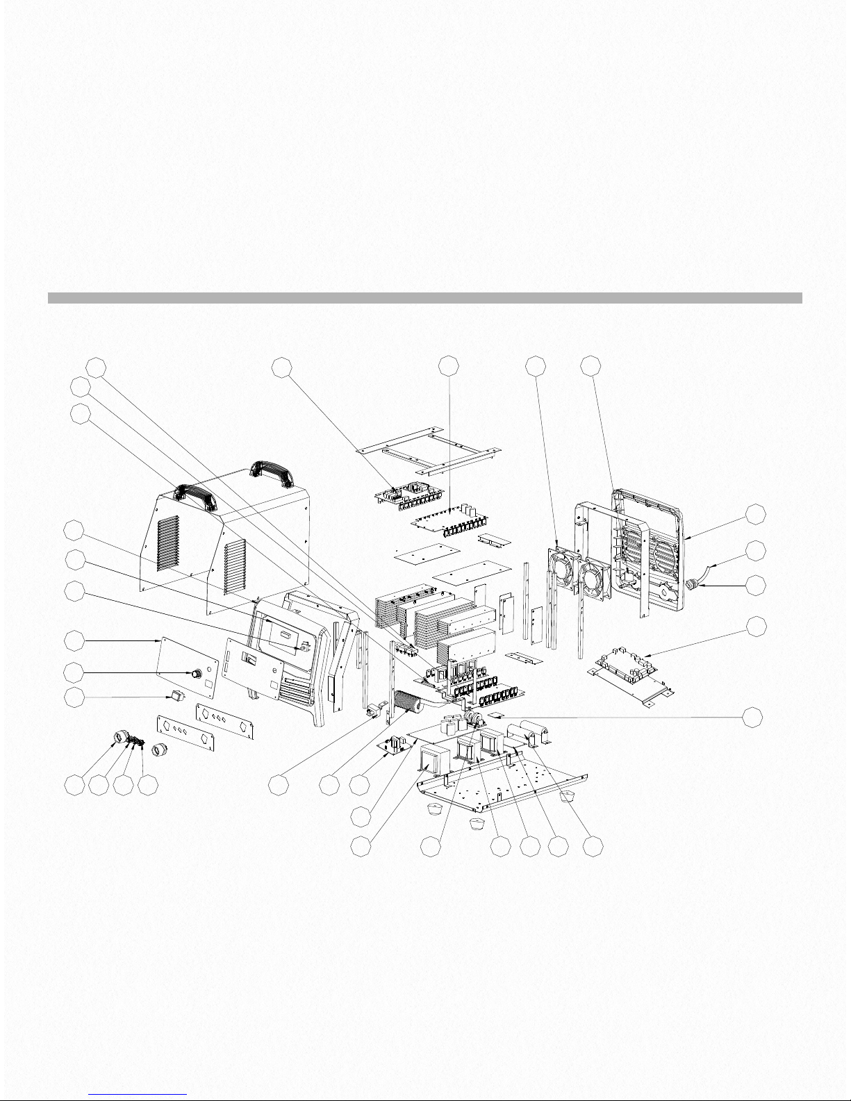
Parts list
8
JT-200D
26
!

JT-200D
JT-315D
No.
Part no
Description
No.
Part no
Description
1
10040581
Summary board
18
10022040
Solenoid value
2
10006625
Silicon bridge
19
10006520
Encoder
3
10020434
Bottom panel
20
10040130
Control board
4
10020604
Arc start board
21
10044448
Front panel
5
10006560
Reactor
22
10044430
Panel overlay (with electro circuit)
6
10020646
Hand switch board
23
10004919
Knob710005295
Glaze resistor
24
10045761
Underneath stick for the front panel
8
10040654
Power transformer
25
10004684
Two pin socket
9
10037776
Secondary driver board
26
10004685
Five pin socket
10
10020665
Secondary power transformer
27
10016390
Water connection
11
10020608
Power transform board
28
10021856
Quick socket
12
10037448
Back Panel
29
10020975
Secondary inverter board A
13
10004935
Power switch
30
10020977
Secondary inverter board B
14
10037303
EMC3110040578
Top board
15
10022057
Fan3210038699
Central board
16
10016389
Connector for water
33
10020826
Power line
17
10021912
Line button
27
No.
Part no
Description
No.
Part no
Description
1
10014869
Front Panel
17
10020665
Secondary power transformer
2
10038551
Panel overlay
18
10037776
Secondary inverter driver board
3
10040580
Summary board
19
10005305
Glaze resistor
4
10006803
Electric current trans
20
10020809
Power line
5
10004946
Power switch
21
10013302
Back panel
6
10004919
Knob2210022039
Solenoid value
7
10021855
Quick Socket
23
10022060
Fan810016390
Water fast socket
24
10020998
Secondary inverter board A
9
10004684
Two pin socket
25
10040579
Top board
10
10001685
Five pin socket
26
10042330
Control board
11
10021002
Arc coil
27
10006520
Encoder
12
10020441
Bottom panel
28
10021912
Line button
13
10006562
Reactor
29
10006625
Silicon bridge
14
10021614
EMC3010020997
Secondary inverter board B
15
10020608
Power transform board
31
10039434
Central board
16
10040655
Power transformer
32
10020646
Hand switch board

JT-315D
28
!

JT-200D / JT-315D DIGITAL AC/DC PULSE TIG/MMA WELDING
MACHINE
Order code ! JT-200D, JT-315D
© Wilkinson Star Limited
Issue 1 January 2014
Product is subject to change without notice
xxix

Appendix
PROGRAMMING GUIDE FOR USERS (TIG MODE)
Skip this chapter over if user-programming function (TIG mode) is not to be used.
4 programmable TIG operation modes (No.16-19) are available for this welding machine, and all the 4 modes are clearly defined
when leaving the factory. Users can freely modify them to meet their special requirements according to the methods provided in
this chapter. Read this chapter carefully and fully understand all contents before the re-programming or modifications of the
operation modes.
1. Operation of the torch trigger
It is the operation mode’s connotation that different operation of the torch trigger during welding lead to different current
waveform. The operation of torch trigger typically includes the following forms:
⊙ Push the torch trigger (↓)
⊙ Release the torch trigger (↑)
⊙ Push the torch trigger and release it at once (↓↑)
⊙ Release the torch trigger and push it at once (↑↓)
⊙ Push the torch trigger twice within 0.5s (↓↑↓or↑↓↑↓)
⊙ Release the torch trigger twice within 0.5s (↑↓↑or↓↑↓↑)
These are the general descriptions of the operation of the torch trigger. In addition, descriptions based on operation times are
used in this chapter.
•
Single operation: Push or release the torch trigger.
•
Double operation: Push and release the torch trigger within 0.5s, or release and push the torch trigger within 0.5s.
•
Triple operation: Push, release and push the torch trigger within 0.5s, or release, push and release the torch trigger within
0.5s.
•
Quartic operation: Push, release, push and release the torch trigger within 0.5s, or release, push, release and push the torch
trigger within 0.5s.
•
2. Coding of operation mode
•
For digital welding machine, the function of TIG operation mode is realized by running an orderly code group. This orderly
code group is called operation mode code sequence, and codes that composing of this sequence code are named operation
30

mode codes. To plan and design a new TIG operation mode is actually to design a code sequence group and to program it
into the welding machine. The code sequence of operation mode is composed of the following.
•
Operation mode code sequence: C0, C1, C2, C3, C4, C5, C6, C7, C8, C9
•
In this sequence, Ci (i stands for code no. 0~9) is a code in the code sequence. The code sequence of an operation mode is
composed of 10 codes, and each code can be a number among 0~99. The meaning of all codes in the code sequence are
detailed as below.
•
C0 is the no. 0 code in the sequence, and it defines the operation time of the operation mode:
•
C0=0~89 stands for that the operation time is 0.0~8.9s.
•
C0=9X stands for that the operation time is (X+1)/10 of the upslope time.
•
C1~C9 respectively stands for no.1~9 code in the sequence and also the operation stipulation of step 1~9. Different values of
these codes stand for different operation stipulations. 100 codes are classified and explained in Attached Table 2 based on
their functions and characteristics, and users should fully understand all those. For welding machine, operation mode is
realized by implementing the code sequences one by one. Here Attached Figure 1 and Attached Figure 2 show the general
steps to implement the code sequences.
Attached Figure 1 Flow chart of operation sequences without code transfer
Attached Figure 2 Flow chart of operation sequences with code transfer
General steps for operation mode code sequence design:
①! Function setting: set operation function according to the welding technical requirements.
②! Function decomposing: decompose function referring to Attached Table 2 to bring out several sub-functions.
③! Code selecting: select appropriate codes referring to Attached Table 2 to realize each sub-function.
④! Sequence composing: arrange the order of codes appropriately to compose applicable code sequences.
Tips in operation mode code sequence design:
31
C
4
C
5
C
6
C7 C2 C3 C8 C9 C
1
Start
Stop
!
C4 C5 C7 C2 C3 C8 C9 C
1
Start
Stop
C
6
!

①! During welding, users always enter into operation mode control after the torch trigger is pushed and arc is successfully
ignited, so users do not need to care about the arc ignition requirements of welding in the code design.
②! Operation mode control will be exited once arc stops. If users want to enter into it again, arc should be ignited for another
time.
③! Operation codes "1X" and "2X" are with a rapid response, while "3X", "4X" and "5X" are with a slow response, because it
takes about 0.5s for the latter to collect the effective changes of torch trigger.
④! Except C0, select “0” in any other codes means no operation and not turning to the next step (i.e. waiting).
⑤! Since as many as 100 kinds of operation codes are available for this machine, there is more than one code sequence to
achieve the specific operation function, and users only need to choose one of them.
⑥! It should be stressed that not all the programming codes can be combined arbitrarily. Some code combinations do not
make sense, and some can achieve some specific functions but against users’ habit. Therefore, users should pay attention
when obtaining code combinations.
20 kinds of TIG operation modes are available for this machine, in which 0-15 are non-programmable, and 16-19 are
programmable. Whether non-programmable ones or programmable ones, they are achieved by their own operation mode code
sequences, which are obtained based on “Operation mode encoding rules” (see Attached Table 1). Please refer to the
description of the operation modes in the text when reading this table.
32

Attached Table 1 TIG operation mode code sequences list
33
Mode
Code sequences
Code sequences
Code sequences
Code sequences
Description
(SEE TEXT FOR DETAILS)
0
Follow mode
1
1T/spot welding mode
2
Standard 2T mode
3
Double operation 2T mode
4
Standard 4T mode
5
Double operation 4T mode
6
Cycle single operation mode
without initial current
7
Cycle single operation mode
with initial current
8
Inner timing operation mode
9
Outer timing operation mode
10
Cycle double operation mode
without initial current
11
Cycle double operation mode
with initial current
12
Single operation 3T mode
13
Double operation 3T mode
14
Real time waveform control
operation mode with initial
current (intermittent up-
down)
15
Real time waveform control
operation mode without initial
current (intermittent up-
down)
16
Manual pulsed single
operation mode
17
Manual pulsed double
operation mode
18
Pulsed welding with fixed
frequency (5Hz) and fixed
duty cycle (50%)
19
Pulsed welding with unfixed
frequency (the cycle is 1/5 of
the upslope time) and fixed
duty cycle (50%)

Attached Table 2 TIG operation mode code function
34
Code
Operation stipulation
Code
Operation stipulation
0X
Immediate executive code:
Execute order X immediately.
5X
Transfer code in torch trigger operation
condition:
Wait for the torch trigger operation. Stop arc if
triple or quartic operation, turn to next step if
single operation, and if double operation:
X=0: Turn to next step
X≠0: Turn to Step X (X=0~9)
1X
Executive code in torch trigger
operation condition:
Wait for the torch trigger operation,
and execute order X when pushing
the torch trigger.
6X
Timing executive code:
Wait for the operation time, and during this
period, no influence if single or double
operation, stop arc if triple or quartic operation.
If no operation of the torch trigger and time is
up, execute order X.
2X
Executive code in torch trigger
operation condition:
Wait for the torch trigger operation,
an d e xe cu t e or de r X w he n
releasing the torch trigger.
7X
Timing transfer code:
Wait for the operation time, and during this
period, turn to next step if single or double
operation, stop arc if triple or quartic operation.
If no operation of the torch trigger:
X=0: Turn to next step
X≠0: Turn to Step X (X=0~9)
3X
Executive code in torch trigger
operation condition:
Wait for the torch trigger operation.
If single operation, execute order
X. Otherwise, stop arc.
8X
Transfer code with torch trigger state:
X=0: Turn to next step immediately
X≠0: Turn to Step X if the torch trigger is
pushed. Otherwise, turn to next step. (X=0~9)
4X
Executive code in torch trigger
operation condition:
Wait for the torch trigger operation.
If single operation, no influence; if
double operation, execute order X;
if triple or quartic operation, stop
arc.
9X
Immediate transfer code:
X=0: Turn to next step
X≠0: Turn to Step X (X=0~9)
The definition of order X:
X=0: Turn to next step
X=1: Go to the initial current and turn to next step
X=2: Go to the preset current and turn to next step
X=3: Go to the pilot arc current and turn to next step
X=4: Upslope and turn to next step
X=5: Stop upslope and turn to next step
X=6: Downslope to the pilot arc and turn to next step
X=7: Downslope till arc stops and turn to next step
X=8: Stop downslope and turn to next step
X=9: Stop arc

3. Operation mode programming
After designing a group of operation code sequence, you can enter into the operation mode programming state and input the
code sequence into the machine. The main steps of operation mode programming are described as below.
①! Access programming state
Press the TIG parameter selecting right shift key to start the machine, and the digital meter displays the flashing “P-2”. After
about 5s, “P-2” disappears and “16” appears, and “
!
” LED turns on, which means that the programming state has been
accessed. Note: If no operation within 5min after accessing the programming state, it will exit automatically.
②! Select operation mode no.
After you access operation mode programming state, “16” displayed on the digital meter stands for the operation mode 16, and
you can select the operation mode to be programmed with the adjustment knob. (Operation mode no. for your selection is
16-19.)
③! Enter into code editing state
After the operation mode no. is determined, you can press the parameter display selecting key, and the operation mode LED
“
!
” flashes. This means you have entered into code editing state.
④! Code no. selecting and code content editing
After you enter into code editing state, the digital meter will display a 3-figure number, of which the flashing higher one stands
for the operation mode code sequence no. and the lower two refer to the code content. You can change the code no. (0~9) by
pressing the TIG parameter selecting right/left shift key and edit the code content (0~99) by turning the adjustment knob.
⑤! Exit code editing state
After you finish editing an operation mode, you can exit code editing state by pressing the parameter display selecting key.
⑥! Exit programming state
After making sure that the edited code is correct, and that you are not going to edit any other operation modes, you can exit
programming state by pressing the MMA parameter selecting key.
The machine will run into normal operation after exiting operation mode programming state. Users can select TIG parameters
appropriately, and check whether the code sequence designed and edited can achieve the desired function by test-welding.
35
 Loading...