


wilkinsonstar.com
Cut 160
Air Plasma Cutting machine
Order code ! JP-160
OPERATOR MANUAL

Your new product
Thank you for selecting this Jasic Technology, Wilkinson Star product.
This product manual has been designed to ensure that you get the most from your new product. Please ensure that you are fully
conversant with the information provided paying particular attention to the safety precautions. The information will help protect
yourself and others against the potential hazards that you may come across.
Please ensure that you carry out daily and periodic maintenance checks to ensure years of reliable and trouble free operation.
Wilkinson Star Limited are a leading supplier of equipment in the UK and our products are supported by our extensive service
network. Call your distributor in the unlikely event of a problem occurring. Please record below the details from your product as
these will be required for warranty purposes and to ensure you get the correct information should you require assistance or
spare parts.
Date purchased! _____________________________________________________
From where ! ! _____________________________________________________
Serial Number! _____________________________________________________
(The serial number will normally be located on the equipment data plate on the underside of the machine or on the rear panel)
Please note products are subject to continual development and may be subject to change without notice
i

Safety Precautions
1
These general safety norms cover both arc welding
machines and plasma cutting machines unless
otherwise noted.
The equipment must only be used for the purpose it was
designed for. Using it in any other way could result in
damage or injury and in breach of the safety rules.
Only suitably trained and competent persons should use the
equipment. Operators should respect the safety of other
persons.
Prevention against electric shock
The equipment should be installed by a qualified person and
in accordance with current standards in operation.It is the
users responsibility to ensure that the equipment is
connected to a suitable power supply. Consult with your
utility supplier if required
If earth grounding of the work piece is required, ground it
directly with a separate cable.
Do not use the equipment with the covers removed.
Do not touch live electrical parts or parts which are
electrically charged.
Turn off all equipment when not in use.
Cables (both primary supply and welding) should be
regularly checked for damage and overheating. Do not use
worn, damaged, under sized, or poorly jointed cables.
Ensure that you wear the correct protective clothing, gloves,
head and eye protection.
Insulate yourself from work and ground using dry insulating
mats or covers big enough to prevent any physical contact
with the work ground.
Never touch the electrode if you are in contact with the work
ground, or another electrode from a different machine.
Do not wrap cables over your body.
Ensure that you take additional safety precautions when you
are welding in electrically hazardous conditions such as
damp environments, wearing wet clothing, and metal
structures. Try to avoid welding in cramped or restricted
positions.
Ensure that the equipment is well maintained. Repair or
replace damaged or defective parts immediately. Carry out
any r e g u l ar ma i n t e n an c e in accordanc e with the
manufacturers instructions.
Safety against fumes and welding gases
Locate the equipment in a well-ventilated position.
Keep your head out of the fumes. Do not breathe the fumes.
Ensure the welding zone is in a well-ventilated area. If this is
not possible provision should be made for suitable fume
extraction.
If ventilation is poor, wear an approved respirator.
Read and understand the Material Safety Data Sheets
(MSDS’s) and the manufacturer’s instructions for metals,
consumable, coatings, cleaners, and de-greasers.
Do not weld in locations near any de-greasing, cleaning, or
spraying operations. Be aware that heat and rays of the arc
can react with vapours to form highly toxic and irritating
gases.
2

Do not weld on coated metals, unless the coating is
removed from the weld area, the area is well ventilated, and
while wearing an air-supplied respirator. The coatings on
many metals can give off toxic fumes if welded.
Prevention against burns and radiation
Arc rays from the welding process produce intense, visible
and invisible (ultraviolet and infrared) rays that can burn eyes
and skin.
Wear an approved welding helmet fitted with a proper shade
of filter lens to protect your face and eyes when welding or
watching
Wear approved safety glasses with side shields under your
helmet.
Never use broken or faulty welding helmets.
Always ensure there are adequate protective screens or
barriers to protect others from flash, glare and sparks from
the welding area. Ensure that there are adequate warnings
that welding or cutting is taking place.
Wear suitable protective flame resistant clothing.
The sparks and spatter from welding, hot work pieces, and
hot equipment can cause fires and burns
Welding on closed containers, such as tanks, drums, or
pipes, can cause them to explode.
Accidental contact of electrode to metal objects can cause
arcs, explosion, overheating, or fire.
Check and be sure the area is safe and clear of inflammable
material before carrying out any welding.
Protection against noise
Some welding and cutting operations may produce noise.
Wear safety ear protection to protect your hearing.
Protection from moving parts
When the machine is in operation keep away from moving
parts such as motors and fans. Moving parts, such as the
fan, may cut fingers and hands and snag garments.
Protections and coverings may be removed for maintenance
and controls only by qualified personnel, after first
disconnecting the power supply cable.
Replace the coverings and protections and close all doors
when the intervention is finished, and before starting the
equipment.
Take care to avoid getting fingers trapped when loading and
feeding wire during set up and operation.
When feeding wire be careful to avoid pointing it at other
people or toward your body.
Always ensure machine covers and protective devices are in
operation.
Precautions against fire and explosion
Avoid causing fires due to sparks and hot waste or molten
metal
Ensure that appropriate fire safety devices are available near
the cutting / welding area.
Remove all flammable and combustible materials from the
cutting / welding zone and surrounding areas
Do not cut/weld fuel and lubricant containers, even if empty.
These must be carefully cleaned before they can be cut/
welded.
Always allow the cut/welded material to cool before touching
it or placing it in contact with combustible or flammable
material.
Do not work in atmospheres with high concentrations of
combustible fumes, flammable gases and dust.
Always check the work area half an hour after cutting to
make sure that no fires have begun.
Risks due to magnetic fields
The magnetic fields created by high currents may affect the
operation of pacemakers or electronically controlled medical
equipment.
Wearers of vital electronic equipment should consult their
physician before beginning any arc welding, cutting, gouging
or spot welding operations.
Do not go near welding equipment with any sensitive
electronic equipment as the magnetic fields may cause
damage.
3

RF Declaration
Equipment that complies with directive 2004/108/EC
concerning electromagnetic compatibility (EMC) and the
technical requirements of EN60974-10 is designed for use in
industrial buildings and not those for domestic use where
electricity is provided via the low voltage public distribution
system. Difficulties may arise in assuring class A
electromagnetic compatibility for systems installed in
domestic locations due to conducted and radiated
emissions.
In the case of electromagnetic problems, it is the
responsibility of the user to resolve the situation. It may be
necessary to shield the equipment and fit suitable filters on
the mains supply.
LF Declaration
Consult the data plate on the equipment for the power
supply requirements.
Due to the elevated absorbance of the primary current from
the power supply network, high power systems affect the
quality of power provided by the network. Consequently,
connection restrictions or maximum impedance
requirements permitted by the network at the public network
connection point must be applied to these systems.
In this case the installer or the user is responsible for
ensuring the equipment can be connected, consulting the
electricity provider if necessary.
Materials and their disposal
The equipment is manufactured with materials, which do not
contain any toxic or poisonous materials dangerous to the
operator.
When the equipment is scrapped, it should be dismantled
separating components according to the type of materials.
Do not dispose of the equipment with normal waste. The
European Directive 2002/96/EC on Waste Electrical and
Electronic Equipment states the electrical equipment that
has reached its end of life must be collected separately and
returned to an environmentally compatible recycling facility.
Handling of Compressed gas cylinders and
regulators
All cylinders and pressure regulators used in welding
operations should be handled with care.
Never allow the electrode, electrode holder or any other
electrically “hot” parts to touch a cylinder.
Keep your head and face away from the cylinder valve outlet
when opening the cylinder valve.
Always secure the cylinder safely
Never deface or alter any cylinder
4

Product Overview
2
Features
The machine adopts advanced inverter technology. The
high inverter frequency of 20KHz greatly reduces the size
and weight of the cutter.
There is a great reduction in magnetic and resistance loss
which enhances the cutting efficiency and energy saving
effect.
A closed loop feedback control provides a stable output
cutting current, even with a mains voltage fluctuation of
±15%.
Non-contact ignition with pilot arc, excellent arc ignition,
can cut rusty and painted metals conveniently.
Excellent dynamic characteristics, high arc stiffness,
smooth cutting surface, high cutting performance.
Current upslope function is available when arc is ignited to
carry out cutting, which can reduce the arc ignition impact.
The constant pilot arc technology can effectively prolong
the lifespan of the electrode and nozzle of the cutting torch.
The cutting current can be accurately preset and step-less
adjustment can be achieved through the preset current
function. Thus, the machine can be used to cut workpieces
with different thicknesses. Low current is used when cutting
thin plate and high current is used when cutting thick plate
to ensure cutting quality and save energy.
With protection function of over/under-voltage, overheating
and low gas pressure inside the machine; gas-check and
2T / 4 T function (automated c u t ting) av a i l a ble; arc
established signal and arc voltage output signal optional;
making it suitable to connect all kinds of CNC machine
tools.
Uses main components from world leading brands, with
high reliability.
Application
Economic and practical using compressed air as the
plasma gas source. The plasma cutter has a wide range of
uses, especially for cutting metal plates of carbon steel,
alloy steel, stainless steel, galvanised steel, copper and
aluminium, etc.
It can be widely used in various industries involving metal
cutting such as boiler and pressure vessel manufacturing,
chemical container manufacturing, power plant installation
and construction industry, metallurgy, chemical engineering,
aeros p a c e, a u tomob i l e a n d e n g ineer i n g v e h ic les
manufacturing and construction, etc.
5

Technical data
3
Tested at the environment temperature of -100 - 400 C
Product design may vary due to customer requirements.
6
MODEL
CUT 160
Rated input voltage (V)
Three phase 400V AC±15%
Rated input frequency (Hz)
50/60
Rated input capacity (KVA)
29.2
Recommended supply fuse (A)
50
Compressed air requirement
170L/Min. 6Bar
No load voltage
330V DC
Cutting current (A)
30-160
Rated output voltage (V)
144
Rated duty cycle (%)
160A @ 60%
Efficiency (%)
85
Power factor
0.99
Insulation class
F
Protection class
IP21S
Arc ignition
HF
Maximum cutting thickness (mm)
60 (Carbon steel)
Weight (kg)
55
Overall size (mm) (L×W×H) without handle
676*333*712

Controls
4
PANEL LAYOUT
7
1
DIGITAL METER
6
CUTTING CURRENT ADJUSTER
2
GAS SELECTOR
7
SECONDARY GAS REGULATOR
3
2T/4T (AUTOMATIC OPERATION)
8
AIR PRESSURE GUAGE
4
TORCH CONNECTOR
9
ALARM INDICATORS
5
WORK RETURN SOCKET

1
2
3
4
5
6
1
AIR INLET
4
FUSE
2
AIR FILTER
5
MAINS INPUT CABLE
3
FAN
6
MAINS ON/OFF SWITCH

Installation
5
Unpacking
Check the packaging for any signs of damage.
Carefully remove the machine and retain the packaging until
the installation is complete.
Location
The machine should be located in a suitable position and
environment. Care should be taken to avoid moisture, dust,
steam, oil or corrosive gases
Place on a secure level surface and ensure that there is
adequate clearance around the machine (at least 20cm) to
ensure natural airflow.
Input connection
Before connecting the machine you should ensure that the
correct supply is available. Details of the machine
requirements can be found on the data plate of the machine
or in the technical parameters shown in the manual.
The equipment should be connected by a suitably qualified
competent person. Always ensure the equipment has a
proper grounding.
Never connect the machine to the mains supply with the
panels removed.
Connection of work cable
Insert the quick plug on the work cable into the quick socket
at the bottom of the front panel of the machine, and tighten
it clockwise. Clamp the workpiece with the work clamp at
the other end of the earth cable.
Connection of cutting torch
Connect the central connection plug on the cutting torch to
the central connection socket of the power supply, and
tighten It clockwise to avoid gas leakage.
Connection of the air supply
The unit should be connected to a suitable, clean and dry air
supply. If there is oil or water in the air a suitable three stage
filter should be connected.
If the quality of air is poor, the cutting speed will decrease,
the cutting quality will lower, the cutting thickness will
reduce, and the service life of wearing parts will be
shortened. In order to obtain the optimal performance, the
maximum particle size of air should be 0.1μm, the maximum
concentration of air should be 0.1mg/m3, the maximum dew
point of air should be -40℃, the maximum oil concentration
should be 0.1mg/m3.
9

The air supply pressure should not exceed 8 bar and normal
cutting pressure will be around 6 bar.
Adjustment of the pilot arc gas
The pilot arc gas of CUT160 (L307) is appropriately set when
leaving factory, and it is unnecessary for users to adjust it
any more. If the operator wants to adjust the pilot arc gas
according to their own preference, the following procedure
should be observed.
1! Disconnect the mains supply
2! Remove the upper cover and adjust the regulator
marked in the figure below to set the pilot arc gas pressure.
If the working gas pressure reaches 6~7 times the
atmospheric pressure, the working gas pressure will be
normal. However, if the pilot arc is unstable and appears
green, it indicates that the pilot arc gas pressure is overly
low, which will cause damage of the wearing parts of the
cutting torch. In this condition, adjust the regulator with a
slotted screwdriver until the pilot arc appears normal. If the
pilot arc snaps and is unstable, it indicates that the pilot arc
gas pressure is overly high. In this condition, adjust the
regulator counterclockwise with a slotted screwdriver until
the pilot arc appears normal.
Installation of the cutting torch
1)! Screw the end of the electrode with screw thread into
the torch head, and tighten it.
2)! Insert the other end of the electrode into the
distributor.
3)! Connect the nozzle with the electrode and distributor.
4)! Connect the protective sleeve with the nozzle, screw
it into the torch head, and tighten it.
Note: Screw the electrode into the torch with an inner
hexagon spanner, and tighten it. Otherwise, the inner thread
of the electrode will be burned.
Introduction of the cutting torch
The plasma cutter CUT160 (L307) uses the Starparts P150
plasma cutting torch for its standard configuration.
The frequency of replacing the wearing parts of the cutting
torch depends on the aspects below:
The thickness of the metal to be cut.
The average cutting length.
Whether it is used for automatic cutting or it is used for
handheld cutting.
Air quality (whether there is oil, water or other contaminants)
Whether it is used to punch on the metal or it is used to cut
from the metal edge.
Whether the distance between the cutting torch and the
workpiece is appropriate when cutting with wearing parts
without protective sleeves.
Whether the cutting height is appropriate.
The quality of the wearing parts used.
Under normal circumstances, the nozzle will wear out first in
hand-held cutting.
The general rule is: The wearing parts will expire after the
practical “arc discharge” time reaches 1~2 hours when it is
used for handheld cutting. The specific time depends on the
above factors. The wearing parts will expire after the
practical “arc discharge” time reaches 3~5 hours when it is
used for automatic cutting. Selecting wearing parts
A complete set of wearing parts for cutting are attached to
the cutting torch P150, including the wearing parts installed
on the cutting torch and the spare electrodes and nozzles
contained in the wearing parts package.
Standard wearing parts for cutting torch P150 are
recommended in order to obtain optimal cutting quality.
WARNING: Plasma arc may cause burns or scalds during
the instantaneous start of cutting torch.
The Plasma arc will be produced at the moment after the
cutting torch is started, so make sure that the power is cut
10
!

P150LT COMPATIBLE CEBORA
Gas: Single • Air Flow: 220 Litres Per Min • Rating: 150 Amp @ 60% Duty Cycle • Cutting Capacity: 35mm Most Materials
TORCH PACKAGES
Item No
Description List Price Each £
C1576LT Hand Torch 6mt Central Fitting 670.55
C1578LT Hand Torch 12mt Central Fitting 792.15
C1577 Machine Torch 6mt Central Fitting 709.34
C1579 Machine Torch 12mt Central Fitting 831.47
MAIN CONSUMABLES
Item
Part Description Pack List Price
No No
Qty
Each £
16 C1007 Spring Holder Protection Nut 1 5.96
17 C1008 Spacer Springs for C1007 5 1.51
18 C1009 Gouging Spacer 1 6.95
19 C1010 Spacer for Contact Cutting - Hand 1 6.69
Use with items 8, 15 & 24
C1011 Spacer for Contact Cutting - Hand 1 9.53
Use with items 10, 15 & 24
C1394 Spacer for Contact Cutting - Hand 1 9.45
Use with items 10, 15 & 24
20 C1012 Spacer - Machine 1 8.36
Use with items 8, 15 & 24
C1013 Spacer - Machine 1 8.36
Use with items 10, 15 & 24
21 C1014 Shield Cup - Hand Max 50 Amp 1 7.23
22 C1015 Spacer for Contact Cutting - Hand 1 7.73
23 C1020 Spacer for Extended Tips High Amp 1 10.99
24 C1016 Locking Nut 1 4.59
25 C1004 Spacer c/w Springs 1 9.04
26 C1005 Spacer Springs 5 0.66
27 C1386 Stand Off Spring 5 1.34
28 C1408 Double Pointed Spacer 1 10.39
29 C1409 Crown Spacer 1 10.87
30 C1406 Gouging Spacer 1 9.45
31 C1509 Extractor for Swirl Ring 1 9.62
32 09706 Handle c/w Micro Switch - Hand Torch 1
33 07301.20 Switch 1 14.75
34 C3055623 Handle Machine Torch 1 32.77
35 C3045012 Wrench for Electrode 1 6.23
36 C970 6mt Cable Assy Hand Torch 1 268.26
C980 12mt Cable Assy Hand Torch 1 425.56
C04320 6mt Cable Assy Machine Torch 1 268.00
C04330 12mt Cable Assy Machine Torch 1 425.00
37 C534-JP Central Connector 1 39.33
MAIN CONSUMABLES
Item
Part Description Pack List Price
No No
Qty
Each £
1 02001 Torch Head 1 224.12
2 C1354 Torch Head - Macine Torch 1 268.33
3 C3160067 'O' Ring - Torch Head 10 0.53
4 C1378 Diffuser 1 4.50
5 C1017 Front Insulator - Vespel 1 32.71
6 C1376 Electrode Hafnium 5 3.15
7 C1377 Swirl Ring Vespel 1 19.66
8 C1371 Cutting Tip 1.1 10 2.45
C1372 Cutting Tip 1.35 10 2.45
C1373 Cutting Tip 1.6 10 2.45
C1374 Cutting Tip 1.8 10 2.45
C1375 Gouging Tip 3.0 10 2.45
9 C1389 Nozzle Retaining Cap 1 24.29
10 C1390 Contact Cutting Tip 1.35 10 3.15
C1391 Contact Cutting Tip 1.6 10 3.15
C1392 Contact Cutting Tip 1.8 10 3.15
11 C1018 Extended Diffuser 1 6.55
12 C1517 Extended Electrode 5 7.02
13 C1369 Extended Contact Cutting Tip- 50 Amp 5 6.32
14 C1001 Extended Tip 1.35 - 90 Amp 5 6.32
C1002 Extended Tip 1.6 - 120 Amp 5 6.32
C1003 Extended Tip 1.8 - 150 Amp 5 6.32
15 C1393 Contact Nozzle Retaining Cap 1 30.74
C1006 Contact Nozzle Ret cap - Long Life 1 42.60
SECONDARY CONSUMABLES
37
19
29
30
28
27
25
18
26
17
16
15
9
13
14
12
11
4
3
5
1
6
7
8
1
0
35
31
36
32
36
34
2
3
5
23
22
24
21
20
© WILKINSON STAR LTD
33

Operation
Before starting any cutting activity ensure that you have
suitable eye protection and protective clothing. Also take
the necessary steps to protect any persons within the
area.
Check that all connections have been made as shown above
Check the following before starting the machine.
1)! Check if the machine is reliably grounded according
to the relevant standard.
2)! Check that there are no bad contacts.
3)! Check if the power cord is connected to the correct
input voltage.
4)! Check if the connecting cables and gas hoses are in
good condition and are not twisted.
Operation
1)! Turn on the power switch on the back panel of the
machine, and the power LED is on.
2) Select the working mode and function.
3) Set cutting current according to the thickness of
workpiece.
4) Bring the copper nozzle of the cutting torch at a distance
of about 2mm between the copper nozzle of the torch and
the workpiece.), and then push the torch trigger. After the
arc is ignited and cutting starts.
5) It is recommended that a torch of maximum length of 6
metres is used. If the torch cable is too long, the
performance of this cutting machine such as arc ignition
will possibly be affected due to the fact that the inner
resistance of the cable will reduce the output voltage.
Notes for cutting operation
1)! Do not touch the hot workpiece with bare hands to
avoid burning.
2)! It is recommended not to ignite the arc in the air if not
necessary, for it will shorten the lifespan of the electrode and
nozzle of the torch.
3)! It is recommended to initiate the cutting from the
edge of workpiece, unless penetration is needed.
4)! Ensure spatter comes from the bottom of workpiece
while cutting. If spatter comes upward from the top of
workpiece, it indicates that the workpiece has not been fully
cut through. This could be due to not enough power or the
cutting torch is moved too fast.
5)! For cutting a round workpiece or to meet precise
cutting requirement, a stencil board or other tools are
needed.
7)! It is recommended to pull the cutting torch while
cutting.
8)! Keep the nozzle of cutting torch upright over the
workpiece, and check if the arc is moving with the cutting
line. Do not bend the cable too much, step on or press upon
the cable to avoid restricting the air flow. The cutting torch
may be burned if the air flow is too low. Keep the cutting
cable away from sharp edges.
9)! When the workpiece is nearly cut off, slow down the
cutting speed and release the torch trigger to stop cutting.
10)! Maintain the torch consumables frequently to prolong
the life
11)! Always ensure the correct consumables are fitted in
the torch. Incorrect items may cause damage to the torch or
machine
Cutting parameters table
For welder training please visit our Academy website at
www.wilkinson-welding-academy.com
12
Cu#ng&capability&(thickness&of&the&mild&steel)
!"#$%&'()"*+,(&-%).+/00(12#)-%+/3"0/(#"&42#5)()"*+,6
7822
!"#$%&'()"*+,(&-%).+/00(1-#+9-/$9()"*+,6
:822
;#<%2"2()"*+,(&-%).+/00(1-#+9-/$9()"*+,6
=822
Cu#ng&mild&steel&with&air&plasma&cu;er
>$#&/(
&-%).+/00(
1226
?@%A)/(
9%#2/&/@((
4B(
)4+&#)&(
5C(1226(
D"*+,(
)"@@/+&(
1E6
F%0&#+)/(
G/&H//+(
&-/(
)"*+,(
&4@)-(#+9(
H4@.C%/)/(
1226
I#0(
J4H(
1KL2%+6
M4@.%+ ,(
,#0(
C@/00"@/(
1N#@6
O/)422/+9/9(
)"*+,(0C//9(
122L2%+6
P8
ΦPQ=
P=8
722
PR8R=S8
T8
ΦPQ=
P=8
722
PR8R::8
78
ΦPQU
P=8
R22
PR8R778
:8
ΦPQU
P=8
R22
PR8RPR8
R8
ΦPQU
P=8
V22
PR8RP88
=8
ΦPQU
P=8
V22
PR8RU8
Cu#ng&stainless&steel&with&air&plasma&cu;er
>$#&/(
&-%).+/00(
1226
?@%A)/(
9%#2/&/@((
4B(
)4+&#)&(
5C(1226(
D"*+,(
)"@@/+&(
1E6
F%0&#+)/(
G/&H//+(
&-/(
)"*+,(
&4@)-(#+9(
H4@.C%/)/(
1226
I#0(
J4H(
1KL2%+6
M4@.%+ ,(
,#0(
C@/00"@/(
1N#@6
O/)422/+9/9(
)"*+,(0C//9(
122L2%+6
:8
WPQU
P=8
R22
PR8RTP8
Cu#ng&aluminium&and&aluminium&alloy&with&air&plasma&cu;er
T8
WPQ=
P=8
722
PR8RR=8

Maintenance and troubleshooting
6
The following operation requires sufficient professional
knowledge on electric aspects and comprehensive
safety knowledge. Make sure the input cable of the
machine is disconnected from the electricity supply and
wait for 5 minutes before removing the machine covers.
In order to guarantee that the arc welding machine works
efficiently and in safety, it must be maintained regularly.
Operators should understand the maintenance methods and
means of arc welding machine operation. This guide should
enable customers to carry on simple examination and
safeguarding by oneself, try to reduce the fault rate and
repair times of the arc welding machine, so as to lengthen
service life of arc welding machine
Troubleshooting
Before arc cutting machines are dispatched from the factory,
they have already been checked thoroughly. The machine
should not be tampered with or altered.
Maintenance must be carried out carefully. If any wire
becomes loose or is misplaced, it maybe potential danger to
user!
Only professional maintenance personnel should repair the
machine!
Ensure the power is disconnected before working on the
machine. Always wait 5 minutes after power switch off
before opening the case.
13
Period
Maintenance item
Daily
examination
Carry out a full visual inspection. Check
for any damage to the machine, leads,
cables and connections. Replace where
necessary.
Switch on the machine and check for any
warning Led’s and general operation
Monthly
examination
Using the dry compressed air to clean the
inside of arc welding machine. Especially
check for build up of dust / debris on
intake grills, main voltage transformer,
inductance, IGBT modules, the fast
recover diode and PCB, etc. Take care
when blowing electronic components and
do not dislodge any wiring connections
Check the security of output connections
and plugs. Replace if signs of overheating.
Yearly
examination
Carry out an annual service. Check earth
continuity and insulation resistance of the
machine at the relevant points.
PLEASE NOTE THIS WORK SHOULD
BE CARRIED OUT BY A TRAINED
COMPETENT PERSON.
Malfunction
Cause and solution
Turn the power switch
( O N / O F F ) t o “ 1 ”
position, but the
machine cannot be
started.
Check and make sure that the power
cable is connected to the power
supply.
Check and make sure that the power
of the main power PCB or circuit cutoff switch box is switched on.
Check and make sure that the circuit
voltage is neither too high nor too
low (the voltage for normal working
is 380V±15%).
Check and make sure that the
machine is not under protection
status.
The abnormal indicator
illuminates with yellow.
Check and make sure that the input
voltage is within the normal range.
Check and make sure that the
machine is not under overheating
protection.
Check and make sure that the
machine is not under overcurrent
protection.

14
Malfunction
Cause and solution
X-/( ,#0( $#).( %+9%)#&4@( %$$"2%+#&/0(
H%&-('/$$4HQ
D-/).( #+9( 2#./( 0"@/( &-#&( &-/( ,#0(
0"CC$'()%@)"%&(%0()4++/)&/9(&4(&-/(C4H/@(
0"CC$'Y(#+9(&-#&(&-/(,#0(0"CC$'( )%@)"%&(%0(
C4H/@/9(4+Q
D-/).(%B( &-/@/( %0( ,#0( $/#.#,/( %+( &-/( ,#0(
0"CC$'( )%@)"%&Y( #+9( &/0&(&-/( C@/00"@/(4B(
&-/(%+C"&(,#0Q
E@)()#++4&(G/(&@#+0B/@@/9(4+&4(&-/(
H4@.C%/)/Q
D$/#+(&-/()4+&#)&(C#@&(4B(&-/( H4@.()$#2C(
#+9(&-/(H4@.C%/)/(&4(/+0"@/(,449(2/&#$3
2/&#$()4+&#)&Q
D-/).(%B(&-/(H4@.()$#2C(%0(9#2#,/9Y(#+9(
@/C#%@(%&(%B(+/)/00#@'Q
X-/( 9%0&#+)/( G/&H//+( &-/( )"*+,( &4@)-(
#+9( H4@.C%/)/( %0( &44( G%,Q( ;4Z/( &-/(
)"*+,( &4@)-( )$40/@( &4( &-/( H4@.C%/)/Y(
#+9(&@'(#,#%+Q
E@)(,4/0(4" &Y( G"&(%&(%0( %,+%&/9(#,#%+(
#[/@( C@/00%+,( 94H+( &-/( )"*+,(
&4@)-(&@%,,/@(B4@(#+4&-/@(52/Q
D-/).( %B( &-/( H/#@%+,( C#@&0( #@/( H4@+( 4@(
9#2#,/9Y(#+9(@/C$#)/(&-/2(%B(+/)/00#@'Q(
D-/ ) .( %B( &-/( ,#0( A$&/@( /$/2/+&( % 0(
C4$$"&/9Y(#+9(@/C$#)/(%&(%B(+/)/00#@'Q
E@)()@#).0(#+9(-%00/0Q
D-/ ) .( %B( &-/( ,#0( A$&/@( /$/2/+&( % 0(
C4$$"&/9Y(#+9(@/C$#)/(%&(%B(+/)/00#@'Q
D-/).(%B( &-/@/(%0( H#&/@(%+( &-/( ,#0()%@)"%&Y(
#+9( %+0&#$$( 4@( @/C#%@( &-/( ,#0( A$&/@(
)4++/)&/9( &4( &-/( C4H/@( 0"CC$'( %B(
+/)/00#@'Q
X-/()"*+,(\"#$%&'(%0(C44@Q
D-/).( #+9( 2#./( 0"@/( &-#&( &-/( )"*+,(
&4@)-(%0(4C/@#&/9()4@@/)&$'Q
D-/).( %B( &-/( H/#@%+,( C#@&0( #@/( H4@+( 4@(
9#2#,/9Y(#+9(@/C$#)/(&-/2(%B(+/)/00#@'Q

Parts
7
15
Position
Part Number
Description
Position
Part Number
Description
1
10004622
Torch connector
29
10050741
Filter protection cover
2
10050737
Front panel
30
10050738
Rear panel
3
10034377
Quick connector
31
10004935
Switch
4
10028232
RC module
32
10046896
Handle
5
10006523
Contactor
33
10004960
Connector
6
10039598
Contactor bracket
34
10039599
Bracket
7
10047520
Base panel
35
10046586
Pressure switch
8
10046462
Reactor
36
10004890
Cable clip
9
10047523
Output fittings
37
10047382
Cable clip bracket
10
10005326
Resistor
38
10023065
Ring M12 x 22
11
10047524
Fitting
39
10047526
Valve bracket
12
10046591
Hall device
40
10046227
Valve
13
10015578
Column
41
10044738
Transformer
14
10016565
Heat sink bracket
42
10020618
EMC board
15
10016592
Heat sink bracket
43
10000778
Power driver board
16
10046605
RC assembly
44
10046423
Program control board
17
10039597
Resistor
45
10047521
Central baffle
18
10028348
Fast recovery diode
46
10001074
Transformer
19
10038347
Fast recovery diode
47
10044293
Hand switch isolation plate
20
10015985
Connector
48
10047527
Regulator bracket
21
10042779
Cylinder
49
10047275
Relief valve
22
10047522
Diode connector
50
10007295
Gauge
23
10044790
Deflector
51
10004918
Knob
24
10036646
Fan
52
10046712
Display
25
10047560
Diode heatsink
53
10004944
Switch
26
10007335
Grill
54
10026117
Switch
27
10007294
Filter
55
10047371
Top cover
28
10050735
Filter bracket
56
10047377
Left cover

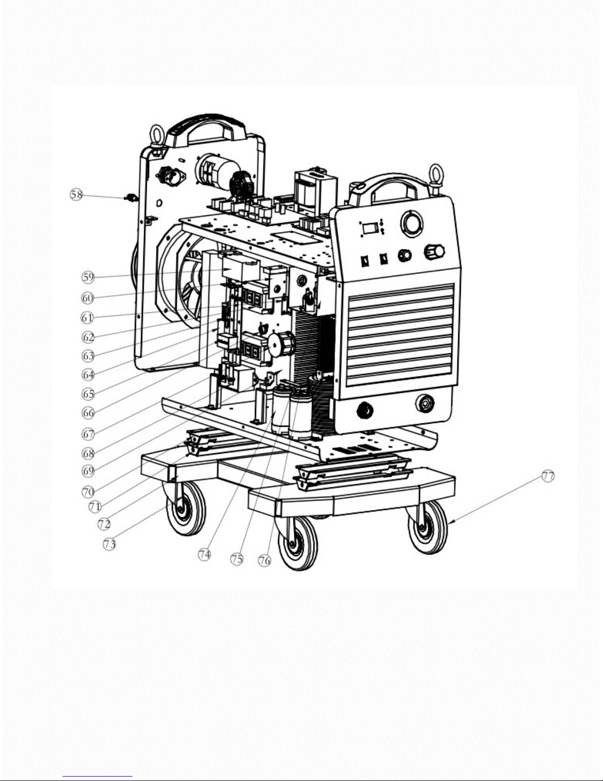
17

Position
Part Number
Description
Position
Part Number
Description
57
10047376
Right cover
68
10035396
IGBT connector
58
10045291
Fuse holder
69
10047561
IGBT heatsink
59
10005913
Non inductive capacitor
70
10053633
Holder 1
60
10046425
Current sampling board
71
10053637
Holder 2
61
10016634
Bracket
72
10053634
Support plate
62
10007233
IGBT module
73
10053217
Wheel
63
10006623
3 phase rectifier
74
10005825
Capacitor
64
10046609
Capacitor
75
10047459
Protection cover
65
10005912
Non inductive capacitor
76
10047525
Capacitor connector
66
10006445
Thermal switch
77
10016534
Swivel wheel
67
10006603
DC filter inductance

CUT 160 AIR PLASMA CUTTING MACHINE
Order code !JP-160
© Wilkinson Star Limited
Issue 1 June 2015
Product is subject to change without notice
xix
 Loading...