

Page 1

Model V-630/650/660/670
Spectrophotometer
Hardware/Function Manual
P/N: 0302-1935D February 2010
Page 2

Safety Considerations
To ensure operation safety, this instrument must be operated correctly and maintained according
to a regular schedule. Carefully read to fully understand all safety precautions in this manual
before operating the instrument. Please take a moment to understand what the signal words
!
WARNING
(1) Safety symbols
WARNING
CAUTION A CAUTION indicates a potentially hazardous situation which, if not
Note A Note provides additional information to help the operator achieve
, CAUTION, and Note mean in this manual.
Instruction manual symbol. If the product is marked with this symbol,
refer to the instrument manuals to protect the instrument against
damage.
!
A WARNING
!
indicates a potentially hazardous situation which, if
not avoided, could result in serious injury or even death.
avoided, may result in minor or moderate injury. It may also be
used to alert against damaging the equipment.
!
Do not proceed beyond a WARNING
or CAUTION notice until you
understand the hazardous conditions and have taken the
appropriate steps.
optimal instrument performance.
i
Page 3
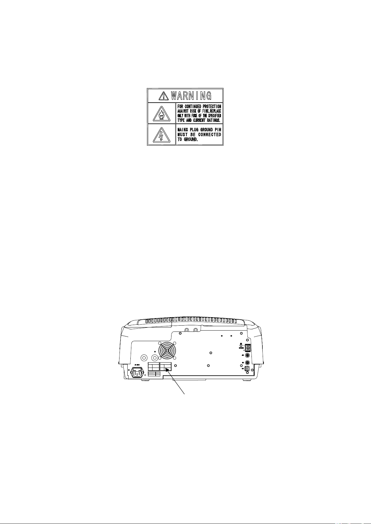
(2) Warning indication
Warnings are indicated at several locations on this instrument. Do not deface or damage the
warning indication.
Figure.1 Warning indication
1) Warning for FUSE (Fig. 2 or Fig. 3)
Only use fuses of the designated rating to protect both operator and instrument from fire and
other hazards. Whenever replacing the lamp, be sure to turn the “Power” switch OFF and
unplug the power cable from the power outlet to avoid the risk of electric shock and other
hazards.
2) Warning for GROUND (Fig. 2 or Fig. 3)
You may receive an electric shock if the instrument is not properly grounded. Correctly ground
the instrument using the grounding terminal on the power board. Do not use water supply
pipes for grounding because they are often made of nonmetals. For the same reason, do not
use gas piping for grounding either.
Warning indication
Figure 2 V-630 Rear Panel
ii
Page 4

Warning indication
Figure 3 V-650/660/670 Rear Panel
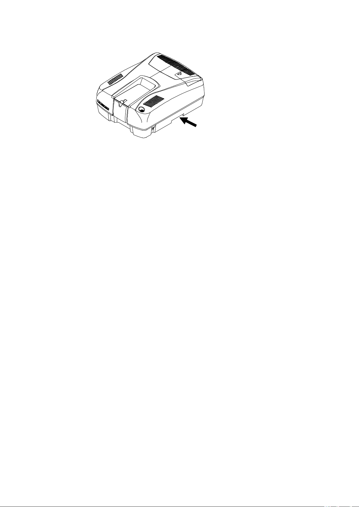
(3) Warning for carrying
These instruments weigh as follows:
V-630: 15.0 kg V-650: 27.0 kg
V-660: 29.0 kg V-570: 28.0 kg
When carrying the instrument, hold the carrying handle at the bottom of the instrument
firmly (See Fig. 4 or Fig. 5).
Carrying handle (both sides)
Figure 4 V-630 side view
iii
Page 5
Carrying handle (both sides)
Figure 5 V-650/660/670 side view
iv
Page 6
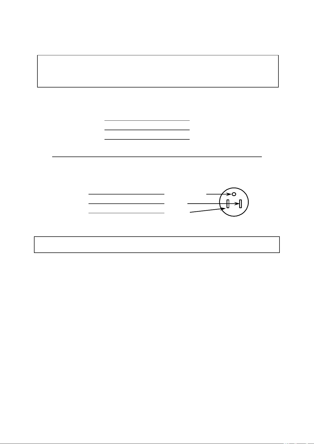
Connecting the Power Cable
Line
WARNING!: The green/yellow ground core of the mains lead must be connected
to a ground that complies with the local electricity supply authority (or
equivalent body). The instrument is dangerous if not correctly
grounded.
240 Volt (nominal) Supply
Wire Color
Ground
Line
Neutral
115 Volt (nominal) Supply
Wire Color
Ground
Neutral
View of pin side of plug
Green/Yellow
Black
White
Green/Yellow
Brown
Blue
Note: Instruments intended for operation at 115 V, 60 Hz are supplied with a mains
cable with a molded plug and socket.
v
Page 7

Regulatory Statement
CE Notice
The symbol indicates compliance of this JASCO system to the EMC (Electromagnetic
Compatibility) and Low Voltage Directives of the European Community. This symbol indicates
that this JASCO system meets the relevant basic safety and health requirements of the EC
Directive based on the following technical standards:
· EN61326-1: "Electrical equipment for measurement, control and laboratory use – EMC
requirements – Part 1: General requirements"
WARNING!: This is a Class A product. In a domestic environment this product
may cause radio interference, in which case the user may be
required to take corrective measures.
· IEC61000-3-2: "Electromagnetic compatibility (EMC) Part 3-2: Limits – Limits for harmonic
current emissions (equipment input current up to and including 16A per phase) "
· IEC61010-1: "Safety requirements for electrical equipment for measurement, control and
laboratory use – Part 1: General requirements"
· A "Declaration of Conformity" in accordance with the above standards has been made and is
on file at JASCO CORPORATION, 2967-5 Ishikawa-machi, Hachioji-shi, Tokyo 192-8537,
JAPAN.
FCC Statement (for USA only)
Federal Communications Commission Radio Frequency Interference Statement
WARNING!: This equipment generates, uses, and can radiate radio frequency
energy. If it is not installed and used in accordance with the
instruction manual, it may cause interference to radio
communications. It has been tested and found to comply with the
limits for a Class A computing device pursuant to Part 15 of FCC
Rules, which are designed to provide reasonable protection against
such interference when operated in a commercial environment.
Operation of this equipment in a residential area is likely to cause
interference, in which case the users at their own expense will be
required to take whatever measures may be required to correct the
interference.
vi
Page 8

Preface
This instruction manual is your guide for using this instrument. It instructs first-time users on how
to use the instrument, and serves as a reference for experienced users.
Before using the instrument, please read this instruction manual carefully, and make sure that the
contents are fully understood. This manual should be easily accessible to the operator at all times
during instrument operation. When not using the instrument, keep this manual in a safe place. If this
instruction manual becomes lost, order a replacement from your local JASCO distributor.
Note: The operating procedure varies with the type of instrument. Operation is
described by type. Read the portion relevant to your instrument.
vii
Page 9

Installation Requirements
To ensure operation safety, observe the following conditions:
(1) Do not operate the instrument under voltage fluctuations exceeding 10% of the
recommended line voltage. Otherwise, the instrument may not function properly.
(2) Frequency or spike noise in the power supply should be minimal.
(3) Ensure that the instrument is grounded.
(4) Operate the instrument in a temperature range of 15 to 30 °C.
(5) Operate the instrument in humidity below 85% (RH). JASCO recommends operating the
instrument in humidity below 60% to avoid the deterioration of the optical components due
to the condensation caused by high humidity.
(6) Operate the instrument in an atmospheric pressure range of 750 to 1060 hPa.
(7) Avoid strong magnetic fields and sources of high frequency. The instrument may not
function properly when near a strong magnetic field or high frequency source.
(8) Avoid vibration from vacuum pumps, electric motors, processing equipment and machine
tools.
(9) Avoid dust and corrosive gas. Do not install the instrument where it may be exposed to dust,
especially in locations exposed to outside air or ventilation outlets that discharge dust
particles.
(10) Do not install the instrument in a location where it may be exposed to direct sunlight.
(11) Install the instrument in a horizontal and stable position. (This includes a table or desk upon
which the instrument is installed.)
(12) Ensure that no air conditioner blows air directly onto the instrument. This may prevent
stable measurement.
(13) Install the instrument in a location that allows easy access for maintenance.
Note: The above conditions do not guarantee optimal performance of this
instrument.
viii
Page 10

Servicing
Contact your local JASCO distributor for instrument servicing. In addition, contact your JASCO
distributor before moving the instrument to another location. Consumable parts should be ordered
according to part number from your local JASCO distributor. If a part number is unknown, give
your JASCO distributor the model name and serial number of your instrument.
Do not return contaminated products or parts that may constitute a health hazard to
JASCO employees.
Notices
(1) JASCO shall not be held liable, either directly or indirectly, for any consequential damage
incurred as a result of product use.
(2) Prohibitions on the use of JASCO software
Copying software for purposes other than backup
Transfer or licensing of the right to use software to a third party
Disclosure of confidential information regarding software
Modification of software
Use of software on multiple workstations, network terminals, or by other methods (not
applicable under a network licensing agreement concluded with JASCO)
(3) The contents of this manual are subject to change without notice for product improvement.
(4) This manual is considered complete and accurate at publication.
(5) This manual does not guarantee the validity of any patent rights or other rights.
(6) If a JASCO software program has failed causing an error or improper operation, this may
be caused by a conflict from another program operating on the PC. In this case, take
corrective action by uninstalling the conflicting product(s).
(7) Windows is a registered trademark of Microsoft Corporation in the United States and other
countries. In general, company names and product names are trademarks or registered
trademarks of the respective companies. However, the TM and ® marks are not used in all
cases in this manual.
(8) JASCO and the JASCO logo are registered trademarks of JASCO Corporation in Japan
and other countries.
(C) JASCO Corporation, 2010. All rights reserved. Printed in JAPAN.
ix
Page 11

Limited Warranty
Products sold by JASCO, unless otherwise specified, are warranted for a period of one year from
the date of shipment to be free of defects in materials and workmanship. If any defects in the
product are found during this warranty period, JASCO will repair or replace the defective part(s)
or product free of charge.
THIS WARRANTY DOES NOT APPLY TO DEFECTS RESULTING FROM THE FOLLOWING:
(1) IMPROPER OR INADEQUATE INSTALLATION
(2) IMPROPER OR INADEQUATE OPERATION, MAINTENANCE, ADJUSTMENT OR
CALIBRATION
(3) UNAUTHORIZED MODIFICATION OR MISUSE
(4) USE OF CONSUMABLE PARTS NOT SUPPLIED BY AN AUTHORIZED JASCO
DISTRIBUTOR
(5) CORROSION DUE TO THE USE OF IMPROPER SOLVENTS, SAMPLES, OR DUE TO
SURROUNDING GASES
(6) ACCIDENTS BEYOND JASCO'S CONTROL, INCLUDING NATURAL DISASTERS
This warranty does not cover the consumable parts listed below:
(1) Tungsten lamp, and other light sources
(2) Mirrors in the light source section, and cell windows
(3) Fuses, batteries, glassware, chart paper and ink
THE WARRANTY FOR ALL PARTS SUPPLIED AND REPAIRS PROVIDED UNDER THIS
WARRANTY EXPIRES ON THE WARRANTY EXPIRATION DATE OF THE ORIGINAL
PRODUCT. FOR INQUIRIES CONCERNING REPAIR SERVICE, CONTACT YOUR JASCO
DISTRIBUTOR AFTER CONFIRMING THE MODEL NAME AND SERIAL NUMBER OF YOUR
INSTRUMENT.
JASCO Corporation
2967-5, Ishikawa-machi, Hachioji-shi
Tokyo 192-8537
JAPAN
x
Page 12

Contents
Safety Considerations............................................................................................... i
Connecting the Power Cable ................................................................................... v
Regulatory Statement ............................................................................................. vi
Preface .................................................................................................................... vii
Installation Requirements..................................................................................... viii
Servicing .................................................................................................................. ix
Notices...................................................................................................................... ix
Limited Warranty ...................................................................................................... x
Contents................................................................................................................... xi
1 Unpacking and Installation ............................................................................... 1
1.1 Unpacking ...............................................................................................................1
1.2 Installation and Connecting Cables......................................................................4
1.2.1 Preparation ...........................................................................................................4
1.2.2 Connecting the Cable of iRM Type.......................................................................4
1.2.3 Connecting the Cable of PC Type ........................................................................4
2 Specifications ....................................................................................................... 6
2.1 V-630 UV/VIS Spectrophotometer Specifications................................................6
2.2 V-650 UV/VIS Spectrophotometer Specifications................................................7
2.3 V-660 UV/VIS Spectrophotometer Specifications................................................8
2.4 V-670 UV/VIS/NIR Spectrophotometer Specifications.........................................9
3 General Description of Instrument.................................................................... 11
3.1 V-630 Spectrophotometer Optical System .........................................................11
3.2 V-650/660/670 Spectrophotometers Optical System .........................................13
3.3 iRM System ...........................................................................................................16
4 Names and Functions of Components ............................................................. 17
4.1 V-630 Spectrophotometer ....................................................................................17
4.1.1 Overview.............................................................................................................17
4.1.2 Rear Panel..........................................................................................................18
4.2 V-650/660/670 Spectrophotometers: Overview..................................................19
4.2.1 Overview.............................................................................................................19
4.2.2 Rear Panel..........................................................................................................20
4.3 Standard Cell Holder (Model USE-753 Rectangular Cell Holder) .....................21
4.4 Intelligent Remote Module (iRM) .........................................................................22
5 Maintenance........................................................................................................ 23
5.1 Cautions for Routine Operation ..........................................................................23
5.2 Cleaning the Sample Compartment ....................................................................23
5.3 Replacement of Consumables ............................................................................24
5.3.1 Replacement of Fuse..........................................................................................24
xi
Page 13

5.3.2 Lamp Replacement and Adjustment of the Light Source Mirror .........................26
5.3.2.1 Lamp replacement ...................................................................................... 26
5.3.2.2 Adjustment of iRM type light source mirror .................................................27
5.3.2.3 Adjustment of PC type light source mirror ..................................................29
5.3.3 Consumable Parts .............................................................................................30
6 Troubleshooting ................................................................................................. 31
xii
Page 14
1 Unpacking and Installation
MODEL
SERIAL No.
POWER
CLASS I
日本分光株式会社
_
AC
WARNING!: This section is intended for trained JASCO servicemen. If the user
attempts unpacking and installation, injury may result. Please leave
unpacking and installation to your JASCO serviceman.
CAUTION: Use this manual when you are unpacking/installing the instrument in
conjunction with a JASCO serviceman’s instructions in the case of a
problem.
1.1 Unpacking
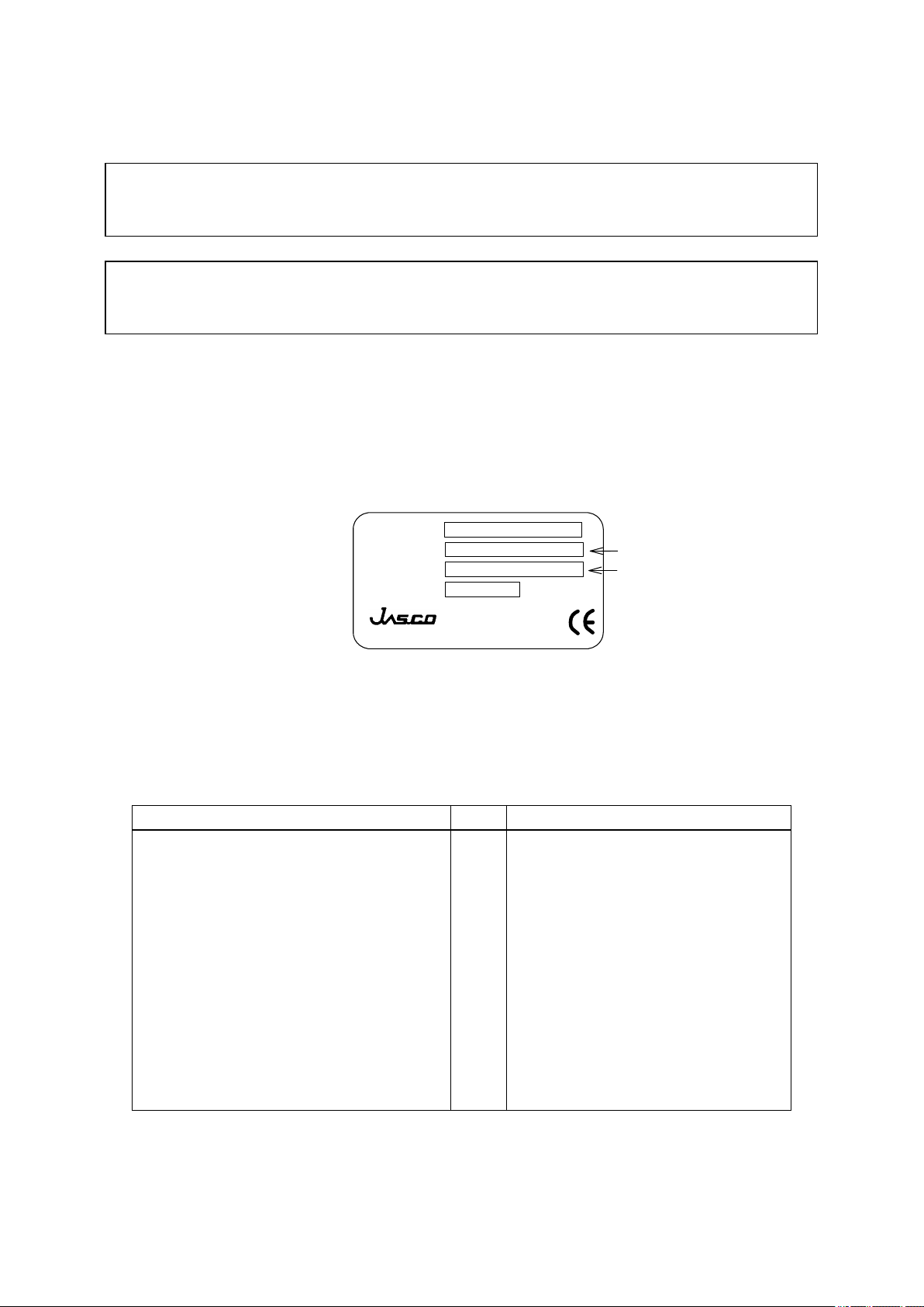
(1) Unpacking the main unit
Take out the main unit from the carton and make sure that the serial No. displayed on the serial
No. label located on the left side of the unit and the serial No. on the inspection certificate agree.
Also ensure that the line voltage is consistent with the power requirement of the instrument.
PROTECT
JASCO Corpration
V 50/60Hz VA
MADE IN JAPAN
192-8537 東京都八王子市石川町 2967-5
Serial Number
Line voltage, frequency
Figure 1.1 Serial No. label
(2) Unpacking the standard accessories
Remove the standard accessories from the carton and check them against the packing list. If you
find any parts missing or damaged items, contact your local JASCO distributor.
Table 1.1 List of Standard Accessories for V-630 iRM Type
Description Qty.
Intelligent remote module(iRM)
iRM touch pen
Compact flash
Card adapter
Holmium glass
Time-lag fuse
AC power cable
Allen wrench
Certificate of inspection
Instruction manual
1
1
1
1
1
2
1
1
1
1 set
Bifunctional holmium glass
holder/shielding plate
For adjustment of the light source
mirror
Comments
1
Page 15

Note 1: Use of the holmium glass does not guarantee wavelength accuracy.
Note 2: Holmium glass holder can also be used as a shielding plate by rotating it
through 90 degree from its usual position.
Table 1.2 List of Standard Accessories for V-650/660/670 iRM Type
Description Qty.
Intelligent remote module(iRM)
iRM touch pen
Compact flash
Card adapter
Holmium glass
Time-lag fuse
AC power cable
Phillips screw driver
Certificate of inspection
Instruction manual
1
1
1
1
1
2
1
1
1
1 set
Bifunctional holmium glass
holder/shielding plate
For adjustment of the light source
mirror
Comments
Note 1: Use of the holmium glass does not guarantee wavelength accuracy.
Note 2: Holmium glass holder can also be used as a shielding plate by rotating it
through 90 degree from its usual position.
Table 1.3 List of Standard Accessories for V-630 PC Type
Description Qty. Comments
Holmium glass
Time-lag fuse
USB cable
AC power cable
Allen wrench
Software setup CD
Certificate of inspection
Instruction manual
1
2
1
1
1
1
1
1 set
Bifunctional holmium glass
holder/shielding plate
For adjustment of the light source
mirror
Note 1: Use of the holmium glass does not guarantee wavelength accuracy.
Note 2: Holmium glass holder can also be used as a shielding plate by rotating it
through 90 degree from its usual position.
2
Page 16

Table 1.4 List of Standard Accessories for V-650/660/670 PC Type
Description Qty.
Holmium glass
Time-lag fuse
USB cable
AC power cable
Phillips screw driver
Software setup CD
Certificate of inspection
Instruction manual
1
2
1
1
1
1
1
1 set
Bifunctional holmium glass
holder/shielding plate
For adjustment of the light source
mirror
Comments
Note 1: Use of the holmium glass does not guarantee wavelength accuracy.
Note 2: Holmium glass holder can also be used as a shielding plate by rotating it
through 90 degree from its usual position.
3
Page 17

1.2 Installation and Connecting Cables
Note:
Be certain to comply with the instrument installation requirements
described in this manual (see page ⅷ). Failure to comply with these
requirements can cause faults with the instrument.
1.2.1 Preparation
Prepare a table which can bear a weight of about 50 kg (differs according to instrument) and has
an area of 700 mm (length) × 600 mm (width) when using the iRM type.
If using a PC as well, prepare a table, which can hold a weight of about 70 kg (differs according to
instrument) and has an area of 700 mm (length) × 1500 mm (width), allowing space for a printer.
Confirm that the power switch of the main unit is off and that the power switch of the PC is off
when using a PC.
1.2.2 Connecting the Cable of iRM Type
WARNING!: You may receive an electric shock if the instrument is not properly
grounded. Correctly ground the instrument using the grounding
terminal on the power board.
CAUTION: For grounding, do not use water pipes, which are often made of
nonmetals. For safety reasons, do not use gas tubing for grounding
either.
Note: Use of a 3-pin power plug with a grounding terminal is recommended.
(1) Connect the cable from the iRM to the “iRM” connector on the rear of V-600.
(2) Connect the AC power cable to the “AC INPUT” connector on the rear of V-600.
Connect the other end of the AC power cable to an electrical outlet.
1.2.3 Connecting the Cable of PC Type
WARNING!: You may receive an electric shock if the instrument is not properly
grounded. Correctly ground the instrument using the grounding
terminal on the power board.
CAUTION: For grounding, do not use water pipes, which are often made of
nonmetals. For safety reasons, do not use gas tubing for grounding
either.
Note: Use of a 3-pin power plug with a grounding terminal is recommended.
(1) Connect the “USB” port located on the rear of V-600 and the USB port on the PC using the
USB cable.
4
Page 18

(2) Connect the PC and the monitor.
(3) Connect the AC power cable to the “AC INPUT” connector on the rear of V-600. Connect
the other end of the AC power cable to an electrical outlet.
(4) Connect the AC power cables to the AC input connector of PC and monitor. Connect the
other ends of the AC power cables to an electrical outlet.
5
Page 19

2 Specifications
The specifications of each model covered in this manual are given below.
2.1 V-630 UV/VIS Spectrophotometer Specifications
Optical system Single monochromator
UV/VIS region: 1200 lines/mm concave grating
Rowland off-circle arrangement
Double beam type
Light source Deuterium lamp: 190 to 350 nm
Halogen lamp: 330 to 1100 nm
Light source exchange
wavelength
Detector Silicon photodiode (S1337)
Wavelength range 190 to 1100 nm
Wavelength accuracy ±0.2 nm (at 656.1 nm, when the room temperature is
Wavelength repeatability ±0.1 nm
Slew speed 12000 nm/min
Spectral bandwidth 1.5 nm fixed
Photometric range 0 to 10000 %T
Photometric accuracy
Photometric repeatability
Stray light 1 % (198 nm KCL 12 g/L aqueous solution)
Baseline stability 0.0004 Abs/hour
Baseline flatness
RMS noise 0.00006 Abs (0 Abs, wavelength: 500 nm, measurement
Power requirements
Dimensions and weight
Note: Values given for wavelength accuracy, wavelength repeatability, photometric
accuracy, photometric repeatability, baseline flatness, and RMS noise are
those obtained more than one hour after the light source was turned on.
Any wavelength between 330 and 350 nm can be
selected.
stabilized.)
-2 to 3 Abs
±0.002 Abs (0 to 0.5 Abs)
±0.003 Abs (0.5 to 1 Abs)
±0.3 %T
(Tested with NIST SRM 930D)
±0.001 Abs (0 to 0.5 Abs)
±0.001 Abs (0.5 to 1 Abs)
0.04 % (220 nm NaI 10 g/L aqueous solution)
0.02 % (340 nm NaNO2 50 g/L aqueous solution)
0.02 % (370 nm NaNO2 50 g/L aqueous solution)
(10 mm cell used)
(Value obtained more than two hours after turning on the
light source, when the room temperature is stabilized,
wavelength: 250 nm, and response: slow.)
±0.0006 Abs
(Value obtained after baseline correction with a
temperature variation of less than 5°C, wavelength: 200
to 1000 nm, response: medium, with smoothing
processing and wavelength scanning speed: 400 nm
/min.)
time: 60 sec, response: medium)
100, 115, 200, 220, 230, 240 V ±10 %, 105 VA
216(H) ´ 486(W) ´ 441(D)mm (excluding protrusions)
15 kg
6
Page 20

2.2 V-650 UV/VIS Spectrophotometer Specifications
Optical system Single monochromator
UV/VIS region: 1200 lines/mm plane grating
Czerny-Turner mount
Double beam type
Light source Deuterium lamp: 190 to 350 nm
Halogen lamp: 330 to 900 nm
Light source exchange
wavelength
Detector Photomultiplier tube
Wavelength range 190 to 900 nm
Wavelength accuracy
Wavelength repeatability
Slew speed 12000 nm/min
Spectral bandwidth 0.1, 0.2, 0.5, 1, 2, 5, 10 nm
Photometric range 0 to 10000 %T
Photometric accuracy
Photometric repeatability
Stray light 1 % (198 nm KCL 12g/L aqueous solution)
Baseline stability 0.0003 Abs/hour
Baseline flatness
RMS noise 0.00003 Abs (0 Abs, wavelength: 500 nm, measurement
Power requirements
Dimensions and weight
Note: Values given for wavelength accuracy, wavelength repeatability, photometric
accuracy, photometric repeatability, baseline flatness, and RMS noise are
those obtained more than one hour after the light source was turned on.
Any wavelength between 330 and 350 nm can be
selected.
±0.2 nm (at a spectral bandwidth of 0.5 nm, wavelength:
656.1 nm, when the room temperature is stabilized.)
±0.05 nm
L2, L5, L10 nm (low stray-light mode)
M1, M2 nm (micro-cell mode)
-2 to 4 Abs
±0.002 Abs (0 to 0.5 Abs)
±0.003 Abs (0.5 to 1 Abs)
±0.3 %T
(Tested with NIST SRM 930D)
±0.001 Abs(0 to 0.5 Abs)
±0.001 Abs(0.5 to 1 Abs)
0.005 %(220 nm NaI 10g/L aqueous solution)
0.005 %(340 nm NaNO2 50g/L aqueous solution)
0.005 %(370 nm NaNO2 50g/L aqueous solution)
(spectral bandwidth: L2 nm, 10 mm cell used)
(value obtained more than two hours after turning on the
light source, when the room temperature is stabilized,
wavelength: 250 nm, response: slow, and spectral
bandwidth: 2nm.)
±0.0003 Abs
(value obtained after baseline correction with a
temperature variation of less than 5°C, wavelength: 200
to 850 nm, response: medium, spectral bandwidth: 2 nm,
and wavelength scanning speed: 400 nm/min with
smoothing processing)
time: 60 sec, response: medium, spectral bandwidth: 2
nm)
100, 115, 200, 220, 230, 240 V ±10 %, 145 VA
270(H) ´ 460(W) ´ 602(D) mm (excluding protrusions)
27 kg
7
Page 21

2.3 V-660 UV/VIS Spectrophotometer Specifications
Optical system Double monochromator
UV/VIS region: 600 lines/mm plane grating
Czerny-Turner mount
Double beam type
Light source Deuterium lamp: 187 to 350 nm
Halogen lamp: 330 to 900 nm
Light source exchange
wavelength
Detector Photomultiplier tube
Wavelength range 187 to 900 nm
Wavelength accuracy
Wavelength repeatability
Slew speed 12000 nm/min
Spectral bandwidth 0.1, 0.2, 0.5, 1, 2, 5, 10 nm
Photometric range 0 to 10000 %T
Photometric accuracy
Photometric repeatability
Stray light 1 % (198 nm KCL 12 g/L aqueous solution)
Baseline stability 0.0003 Abs/hour
Baseline flatness
RMS noise 0.00005 Abs (0 Abs, wavelength: 500 nm, measurement
Power requirements
Dimensions and weight
Any wavelength between 330 and 350 nm can be
selected.
±0.1 nm (at a spectral bandwidth of 0.5 nm, wavelength:
656.1nm, when the room temperature is stabilized.)
±0.05 nm
L2, L5, L10 nm (low stray-light mode)
M1, M2 nm (micro-cell mode)
-2 to 6 Abs
±0.002 Abs (0 to 0.5 Abs)
±0.003 Abs (0.5 to 1 Abs)
±0.3 %T
(Tested with NIST SRM 930D)
±0.001 Abs (0 to 0.5 Abs)
±0.001 Abs (0.5 to 1 Abs)
0.00008 % (220 nm NaI 10 g/L aqueous solution)
0.00008 % (340 nm NaNO2 50 g/L aqueous
solution)
0.00008 % (370 nm NaNO2 50g/L aqueous
solution)
(spectral band width: L2 nm, 10 mm cell used)
(Value obtained more than two hours after turning on the
light source, when the room temperature is stabilized,
wavelength: 250 nm, response: slow, and spectral
bandwidth: 2nm)
±0.0005Abs
(Value obtained after baseline correction with a
temperature variation of less than 5°C, wavelength: 200 to
800 nm, response: medium, spectral bandwidth: 2 nm,
smoothing processing and wavelength scanning speed:
400 nm/min)
time: 60 sec, response: Medium, spectral bandwidth: 2
nm)
100, 115, 200, 220, 230, 240 V ±10 %, 145 VA
270(H) ´ 460(W) ´ 602(D) mm (excluding protrusions)
29 kg
8
Page 22

Note: Values given for wavelength accuracy, wavelength repeatability, photometric
accuracy, photometric repeatability, baseline flatness, and RMS noise are
those obtained more than one hour after the light source was turned on.
2.4 V-670 UV/VIS/NIR Spectrophotometer Specifications
Optical system Single monochromator
UV/VIS region: 1200 lines/mm plane grating
NIR region: 300 lines/mm plane grating
Czerny-Turner mount
Double beam type
Light source Deuterium lamp: 190 to 350 nm
Halogen lamp: 330 to 2700 nm
Light source exchange
wavelength
Detector Photomultiplier tube
Detector exchange
wavelength
Wavelength range 190 to 2700 nm
Wavelength accuracy
Wavelength repeatability
Slew speed 12000 nm/min (UV/VIS region)
Spectral bandwidth 0.1, 0.2, 0.5, 1, 2, 5, 10 nm (UV/VIS region)
Photometric range 0 to 10000 %T
Photometric accuracy
Photometric repeatability
Stray light 1 % (198 nm KCL 12g/L aqueous solution)
Any wavelength between 330 and 350 nm can be selected.
PbS photoconductive cell
Any wavelength between 750 and 900 nm can be selected.
The diffraction grating is set to the same wavelength as the
detector exchange wavelength.
Using the optional wavelength extension accessory,
wavelength of up to 3200 nm can be measured.
±0.3 nm (at a spectral bandwidth of 0.5 nm, UV/VIS region,
when the room temperature is stabilized.)
±1.5 nm (at a spectral bandwidth of 2.0 nm, NIR region,
when the room temperature is stabilized.)
±0.05 nm (at a spectral bandwidth of 0.5 nm, UV/VIS
region)
±0.2 nm (at a spectral bandwidth of 2.0 nm, NIR region)
48000 nm/min (NIR region)
L2, L5, L10 nm (low stray-light mode, UV/VIS region)
M1, M2 nm (micro-cell mode)
0.4, 0.8, 1, 2, 4, 8, 20, 40 nm (NIR region)
L8, L20, L40 nm (low stray-light mode, NIR region)
M4, M8 nm (micro-cell mode, NIR region)
-2 to 4 Abs (UV/VIS region)
-2 to 3 Abs (NIR region)
±0.002 Abs (0 to 0.5 Abs)
±0.003 Abs (0.5 to 1 Abs)
±0.3 %T
(Tested with NIST SRM 930D)
±0.001 Abs (0 to 0.5 Abs)
±0.001 Abs (0.5 to 1 Abs)
0.005 % (220 nm NaI 10g/L aqueous solution)
0.005 % (340 nm NaNO2 50g/L aqueous solution)
0.005 % (370 nm NaNO2 50g/L aqueous solution)
(spectral band width: L2 nm, 10 mm cell used)
0.04% (1690 nm H2O 10 mm cell used)
9
Page 23

0.1% (1690 nm CH2Br2 50 mm cell used)
(spectral bandwidth: L8 nm)
Baseline stability 0.0003 Abs/hour
(Value obtained more than two hours after turning on the
light source, when the room temperature is stabilized,
wavelength: 250 nm, response: slow, and spectral
bandwidth: 2nm)
Baseline flatness
RMS noise 0.00003 Abs (0 Abs, wavelength: 500 nm, measurement
Power requirements
Dimensions and weight
±0.0005 Abs
(Value obtained after baseline correction with a temperature
variation of less than 5°C, wavelength: 200 to 850 nm,
response : medium, spectral bandwidth: 2 nm, smoothing
processing and wavelength scanning speed: 400 nm/min,
spectral bandwidth: 8 nm in wavelength 850 to 2500 nm)
time 60 sec, response: medium, spectral bandwidth: 2 nm)
100, 115, 200, 220, 230, 240 V ±10 %, 145 VA
270(H) ´ 460(W) ´ 602(D) mm (excluding protrusions)
28 kg
Note: Values given for wavelength accuracy, wavelength repeatability, photometric
accuracy, photometric repeatability, baseline flatness, and RMS noise are
those obtained more than one hour after the light source was turned on.
10
Page 24

3 General Description of Instrument
D D
Sam
F G
WI
5
M
2
S
2
4
WI D
2
S
F
G
BS
D
Sam
Ref
Deuterium lamp
H
alogen lamp
Slit
Grating
Bea
m
spl
itter
Detector
Sample beam
Reference beam
3.1 V-630 Spectrophotometer Optical System
(1) Optical System
The V-630 is designed to measure the absorption spectrum of a sample over a wavelength range
of 190 to 1100 nm. The light sources used are a deuterium (D2) lamp (190 to 350 nm) for the UV
region, and a halogen (WI) lamp (330 to 1100 nm) for the VIS/NIR region. The light from the light
source is focused and enters the monochromator. The light is dispersed by the grating in the
monochromator and focused onto the exit slit. The light that passes through the exit slit is
monochromated. This light is split into two beams, one going to the sample to be measured and
the other to the reference sample such as a solvent. The light that has passed through the
sample and the reference sample is incident upon the silicon photodiode.
M
1
D
Ref
M
M
2
Filter
S
3
(BS)
M
Figure 3.1 V-630 Optical system
(2) Electrical System
A schematic diagram of the electrical system used in the V-630 is shown in Fig. 3.2. The light
detected by the silicon photodiode is converted into an electrical signal and, after being subjected
to synchronous rectification, is converted into a digital signal and is sent to the computer. The
signal processed by the computer is displayed on the monitor as digital data or a spectrum.
Actions such as light source exchange, wavelength drive, filter drive, etc. are controlled by the
computer.
11
Page 25

Figure 3.2 V-630 electrical system diagram
12
Page 26

3.2 V-650/660/670 Spectrophotometers Optical System
(1) Optical System
The optical system varies between the models of the instrument. Figures 3.3 through 3.5 show
the optical systems. The V-650 measures the absorption spectrum of a sample over a
wavelength range of 190 to 900 nm, the V-660 measures the absorption spectrum of a sample
over a wavelength range of 187 to 900 nm and the V-670 measures the absorption spectrum of a
sample over a wavelength range of 190 to 2700 nm (can be extended to 3200 nm using the
optional wavelength extension accessory). The light sources used are a deuterium (D2) lamp (187
to 350 nm) for use in the UV region and a halogen (WI) lamp (330 to 2700 nm) for use in the
VIS/NIR region. The light from the light source is focused and enters the monochromator. It is
dispersed by the grating in the monochromator and focused on to the exit slit. The light that
passes through the exit slit is monochromated. This light is split into two beams by a sector mirror,
one going to the sample to be measured and the other to the reference sample such as a solvent.
The beams that have passed through the sample and reference sample are alternately incident
upon the detector (that is a photomultiplier tube or a PbS photoconductive cell).
WI, D2 : Light source
M : Mirror
S : Slit
F : Filter
G : Grating
M8 : Sector mirror
PM : Detector
Sam : Sample beam
Ref : Reference beam
W : Window
Figure 3.3 V-650 Optical system
13
Page 27

WI, D2 : Light source
M : Mirror
S : Slit
F : Filter
G : Grating
M8 : Sector mirror
PM : Detector
Sam : Sample beam
Ref : Reference beam
W : Window
Figure 3.4 V-660 Optical system
WI, D2 : Light source
M : Mirror
S : Slit
F : Filter
G : Grating
M8 : Sector mirror
PM : UV/VIS Detector
PbS : NIR detector
Sam : Sample beam
Ref : Reference beam
W : Window
Figure 3.5 V-670 Optical system
14
Page 28

(2) Electrical System
Figure 3.6 shows a schematic diagram of the electrical system used in the V-650, V-660 and V670 spectrophotometers. The light incident upon the photomultiplier tube or PbS photoconductive
cell is converted into an electrical signal and, after being subjected synchronous rectification, it is
converted into a digital signal. The signal processed by the computer is displayed on the monitor
as digital data or a spectrum.
Actions such as light source exchange, wavelength drive, slit drive, filter drive, etc. are controlled
by the computer.
Figure 3.6 V-650/660/670 electrical system diagram
15
Page 29

3.3 iRM System
Figure 3.7 shows the schematic diagram of the iRM system.
The iRM can be connected to the V-630/650/660/670 spectrophotometers, and can be used to
control measurement, printing, and saving. Various menus can be selected using the touch panel
key on the color LCD.
Figure 3.7 iRM system diagram
16
Page 30

4 Names and Functions of Components
4.1 V-630 Spectrophotometer
4.1.1 Overview
Sample compartment
Light source lid
“START” switch
“Power" switch
Fixing screws
Figure 4.1 V-630 appearance
Name Function
Sample compartment Slide the lid to the back to open it. The single position cell holder
(the standard cell holder) is installed. The cell holder located
toward the front is the sample cell holder, and the one located
toward the rear is the reference cell holder.
Fixing screws Fixes the standard cell holder in position. Loosen the two fixing
screws, pull the standard cell holder toward you a little and lift to
remove it.
“Power” switch When the switch is pressed on, the power supply is turned on.
“START” switch Switch to start measurement. The lamp flashes during
measurement.
Light source lid The light source is housed here.
17
Page 31

4.1.2 Rear Panel
"
AUX
"
"
GND
"
" iRM "
Fuse
" RECORDER "
" USB "
"AC INPUT"
Warning indications
Figure 4.2 V-630 rear panel
Name Function
AC INPUT The power supply input connector. Connect with the power cable.
Fuse Fuses for the main unit
Warning
indications
GND Grounding terminal
RECORDER Terminal for analog output.
AUX Auxiliary connector for connecting an accessory.
iRM Connector for connecting the cable of iRM.
USB Connector for connecting the cable with PC.
Warning indications for fuse and ground.
The value specified by setting the scale of [Abs/%T meter] program is
recorded in the range 0 to 1 V.
18
Page 32

4.2 V-650/660/670 Spectrophotometers: Overview
Light source lid
"
START
" switch
4.2.1 Overview
Sample compartment
Fixing screws
"Power" switch
Figure 4.3 V-650/660/670 appearance
Name Function
Sample compartment Slide the lid back to open it. The single position cell holder (the
standard cell holder) is installed. The cell holder located toward
the front is the sample cell holder, and the one located toward the
rear is the reference cell holder.
Fixing screws Fixes the standard cell holder in position. Loosen the two fixing
screws, pull the standard cell holder toward you a little and lift to
remove it.
“Power” switch When the switch is pressed on, the power supply is turned on.
“START” switch Switch to start measurement. The lamp flashes during
measurement.
Light source lid The light source is housed here.
19
Page 33

4.2.2 Rear Panel
"AC I
NPUT
"
Fuse
"
AUX
"
"
GND
"
"
USB
"
" RECORDER "
" iRM "
Warning indications
Figure 4.4 V-650/660/670 rear panel
Name Function
AC INPUT The power supply input connector. Connect with the power cable.
Fuse Fuses for the main unit.
Warning
indications
GND Grounding terminal.
RECORDER Terminal for analog output.
AUX Auxiliary connector for connecting an accessory.
iRM Port for connecting the cable of iRM.
USB Port for connecting the cable with PC.
Warning indications for fuse and ground.
The value specified by setting the scale of [Abs/%T meter] program is
recorded in the range 0 to 1 V.
20
Page 34

4.3 Standard Cell Holder (Model USE-753 Rectangular Cell Holder)
Accessory information
Accessory information
Reference cell holder
Sample cell holder
contact
Fixing screw holes
chip
Figure 4.5 Standard cell holder (Model USE-753 Rectangular cell holder)
Name Function
Sample cell holder Mount the cell containing the sample here.
Reference cell holder Mount the cell containing the reference solvent here.
Fixing screw holes Screw holes for attaching the standard cell holder.
Accessory information
Memory chip for accessory information.
chip
Accessory information
Contact pin for reading accessory information.
contact
21
Page 35

4.4 Intelligent Remote Module (iRM)
Display panel
Cable
(Appearance)
Connector for printer
(USB interface)
Connector for printer
(Parallel I/0 interface)
Card slot
Connector for accessory
(Rear panel)
Figure 4.6 Intelligent remote module
Name Function
Display panel 320x240 pixel color LCD. Displays wavelength, absorbance,
measurement parameters, etc. Also used for selecting menus and
editing measurement parameters via the touch key pad.
Cable Connects to the main unit.
Card slot
Connector for printer
Connector for
accessory
Accepts a compact flash card or a flash ATA card. Card adapter is
necessary for the compact flash card.
Connector for the printer (USB interface and parallel I/O interface).
Connects to an accessory.
22
Page 36

5 Maintenance
Pay attention to the instrument operating environment and always keep it clean so that the
instrument can be used in a stabilized condition over a long period.
This section contains instructions on how to clean the sample compartment when a sample is
spilt, and on replacing consumables.
It is recommended that the validation program be used for checking the performance of the
instrument.
5.1 Cautions for Routine Operation
(1) Before operating the instrument, allow the instrument to warm-up for at least 15 minutes after
turning the power on.
(2) Do not place anything on the instrument.
(3) After completing measurements, remove the sample from the sample compartment.
5.2 Cleaning the Sample Compartment
If a sample is spilt in the sample compartment, quickly wipe up the spillage using gauze or a
similar material, remove the cell holder, and clean it using the following procedure.
CAUTION: Use ethanol to clean the sample compartment. Do not use other types
of organic solvent as this may remove the instrument paint.
(1) Removing the standard cell holder
a) Open the sample compartment lid and loosen the two fixing screws located on the front
underside of the sample compartment by hand (see Fig. 4.1 or Fig. 4.3).
b) Pull the standard cell holder toward you a little and lift to remove it.
(2) Cleaning the standard cell holder
<<When the sample is soluble in water>>
Wipe up the spilt sample using gauze or a similar material. Remove any trace of the spillage
with gauze soaked in water. Finally, remove any moisture with gauze and then allow drying.
<<When the sample is insoluble in water>>
Wipe up the spilt sample using gauze or a similar material. Remove any trace of the spillage
with gauze soaked in ethanol. Finally, remove any moisture with gauze and then allow drying.
(3) Remounting the standard cell holder
a) Locate the standard cell holder over the two positioning pins on the main unit certainly
and move it toward to the back.
b) Ensure that light is incident upon the center of the cell holder. To check it visually, set the
wavelength to 500 nm and place a piece of white paper in front of the cell holder.
c) Firmly tighten the two fixing screws of the bottom of the standard cell holder.
23
Page 37

5.3 Replacement of Consumables
5.3.1 Replacement of Fuse
WARNING!: Only use fuses of the rated capacity to prevent injury to personnel
and overheating of the instrument.
WARNING!: To avoid electric shock, always turn off the power switch and unplug
the AC power cable from the outlet before replacing a fuse.
V-630 uses 2A time-lag fuses (P/N: 5840-H102A 5pcs/set) when using a 100 V voltage supply
and 1.6 A time-lag fuses (P/N: 5840-H106A 5pcs/set) when using a 200 V voltage supply. V650/660/670 use 2.5 A time-lag fuses (P/N: 5840-H103A 5pcs/set) when using a 100 V voltage
supply and 1.6 A time-lag fuses (P/N: 5840-H106A 5pcs/set) when using a 200 V voltage supply.
(V-630)
100 V to 120 V: 2.0 A time-lag fuse
200 V to 240 V: 1.6 A time-lag fuse
(V-650/660/670)
100 V to 120 V: 2.5 A time-lag fuse
200 V to 240 V: 1.6 A time-lag fuse
Fuse
Figure 5.1 V-630 rear panel
Fuse
Figure 5.2 V650/660/670 rear panel
24
Page 38

Fuse
s
Note: Replace both fuses, even if only one is burned out.
(1) Turn off the power and disconnect the AC power cable from the “AC INPUT”.
(2) Insert a flat-head screwdriver under the fuse holder, then pull forward to remove the fuses
with the holder (Fig. 5.3).
(3) Take the old fuses out of the holder, and replace with new ones. Insert the fuse holder in its
original position.
(4) Plug the power cable into the “AC INPUT” and turn the power switch on, then check that the
instrument can be operated.
Note: If the fuses burn out again soon after replacement, contact your nearest local
JASCO distributor.
Fuse holder
Figure 5.3 Replacement of fuse
25
Page 39

5.3.2 Lamp Replacement and Adjustment of the Light Source Mirror
The lifetime of both the deuterium (D2) lamp and the halogen (WI) lamp is approx. 1000 hours.
After prolonged use, the noise level in the measured data will increase because of the low light
intensity.
5.3.2.1 Lamp replacement
WARNINGS!:
(1) The lamp is hot when lit. Therefore, before replacing the lamp,
switch off the light source and wait for at least 15 minutes.
(2) To avoid electric shock, turn off the power and remove the power
cable from the outlet.
Notes:
(1) Never loosen any screws other than those required for lamp
replacement.
(2) When handling the lamp, wear clean cloth gloves. Never handle the
lamp with bare hands.
(3) Never touch the mirror or any other optical elements by hands.
(4) If the lamp surface is contaminated, clean it with gauze soaked in
ethanol and wipe it with dry clean gauze.
<<Replacement of halogen (WI) lamp>>
(1) Slide the outer lid of the light source unit to remove it and then remove the inner lid (Fig. 5.4).
The way to remove the lamp is the same for V-630, even though V-650/660/670 is shown in
figure 5.4.
Light source lid (inner side)
Light source lid (outside)
Figure 5.4 Removal of light source lid (V-650/660/670)
(2) Remove the halogen lamp from the socket.
(3) Insert a new halogen lamp into the socket (Fig. 5.5 or 5.6).
(4) Adjust the light source mirror as described in Section 5.3.2.2 or 5.3.2.3.
26
Page 40

<<Replacement of deuterium lamp>>
2
WI lamp stopper
2
A
djustment screw
WI
lamp
D2 lamp stopper
Adjuatment screw
(1) Slide the outer lid of the light source unit to remove it.
(2) Remove the deuterium lamp from the socket.
(3) Insert a new deuterium lamp into the socket (Fig. 5.5 or 5.6).
(4) Adjust the light source mirror as described in Section 5.3.2.2 or 5.3.2.3.
lamp stopper
D
Adjustment screw
lamp
D
WI lamp
Figure 5.5 Light source unit (V-630)
WI lamp stopper
Adjustment screw
D
lamp
2
Figure 5.6 Light source unit (V-650/660/670)
5.3.2.2 Adjustment of iRM type light source mirror
When the light source is replaced, if the beam from the lamp is not incident upon the entrance slit
correctly, problems will occur, such as insufficient light intensity, a non-linear baseline, and
incorrect values for measurements. Whenever the lamp is replaced, be sure to adjust the light
source mirror.
WARNINGS!:
(1) The lamp is hot when lit. Do not touch with bare hands.
(2) Wear glasses (ordinary glasses or sunglasses) during adjustment to
(3) Do not touch the wiring either with your hand or with a screwdriver.
Note: Never loosen any screws other than those required for lamp replacement.
protect your eyes from ultraviolet rays.
Contact with the wiring may cause electric shock.
27
Page 41

<<Adjustment of light source mirror for halogen lamp>>
(1) Turn on the instrument and the halogen lamp.
(2) Select [Environment] from the main menu to display the [Environment] menu.
(3) Select [Single Beam Measurement] from the [Environment] menu to display the single beam
measurement window.
(4) Set parameters as follows.
V-630 measurement parameters V-650/660/670 measurement parameters
Photometric mode Sam Photometric mode Sam
Response Fast Response Fast
Band Width 2.0 nm
PMT Voltage 200 V
(5) Set the wavelength to 500 nm.
(6) Slide the lid of the light source unit to remove it (see Fig. 5.4).
Note: Do not mistakenly loosen other screws instead of the adjustment screw.
(7) Turn the halogen lamp stopper adjustment screw (Fig. 5.5 or 5.6) and search for a position
where the value displayed on the monitor is a maximum.
(8) Replace the lid of the light source unit.
<<Adjustment of light source mirror for deuterium lamp>>
(1) Turn on the instrument, and light the deuterium lamp.
(2) Select [Environment] from the main menu to display the [Environment] menu.
(3) Select [Single Beam Measurement] from the [Environment] menu to display the single beam
measurement window.
(4) Set parameters as follows.
V-630 measurement parameters V-650/660/670 measurement parameters
Photometric mode Sam Photometric mode Sam
Response Fast Response Fast
Band width 2.0 nm
PMT voltage 300 V
(5) Set the wavelength to 250 nm.
(6) Slide the lid of the light source unit to remove it (see Fig.5.4).
Note: Do not mistakenly loosen other screws instead of the adjustment screw.
(7) Turn the deuterium lamp stopper adjustment screw (Fig. 5.5 or Fig. 5.6) and search for a
position where the value displayed on the monitor is a maximum.
(8) Replace the of the light source unit.
28
Page 42

5.3.2.3 Adjustment of PC type light source mirror
When the light source is replaced, if the beam from the lamp is not incident upon the entrance slit
correctly, problems will occur, such as insufficient light intensity, a non-linear baseline, and
incorrect values for measurements. Whenever the lamp is replaced, be sure to adjust the light
source mirror.
WARNINGS!:
(1) The lamp is hot when lit. Do not touch with bare hands.
(2) Wear glasses (ordinary glasses or sunglasses) during adjustment to
protect your eyes from ultraviolet rays.
(3) Do not touch the wiring either with your hand or with a screwdriver.
Contact with the wiring may cause electric shock.
Note: Never loosen any screws other than those required for lamp replacement.
<<Adjustment of light source mirror for halogen lamp>>
(1) Turn on the instrument.
(2) Start [Abs/%T meter] from the [Spectra Manager] window and appears the [Abs/%T meter]
window.
(3) Set parameters as follows.
V-630 measurement parameters V-650/660/670 measurement parameters
Photometric mode Sample Photometric mode Sample
Response Fast Response Fast
Wavelength 500 nm Band Width 2.0 nm
Halogen lamp Turn on Wavelength 500 nm
HT Voltage 200 V
Halogen lamp Turn on
(4) Slide the lid of the light source unit to remove it.
Note: Do not mistakenly loosen other screws instead of the adjustment screw.
(5) Turn the WI lamp stopper adjustment screw (Fig. 5.5 or Fig. 5.6) and search for a position
where the value displayed on the monitor is a maximum.
(6) Replace the lid of the light source unit.
<<Adjustment of light source mirror for deuterium lamp>>
(1) Turn on the instrument.
(2) Start [Abs/%T meter] from the [Spectra Manager] window and appears the [Abs/%T meter]
windows.
(3) Set parameters as follows.
V-630 measurement parameters V-650/660/670 measurement parameters
Photometric mode Sample Photometric mode Sample
Response Fast Response Fast
Wavelength 250 nm Band Width 2.0 nm
Deuterium lamp Turn on Wavelength 250 nm
PMT Voltage 200 V
Deuterium lamp Turn on
29
Page 43

(4) Slide the id of the light source unit to remove it (see Fig.5.4).
Note: Do not loosen screws other than the adjustment screw for the stopper.
(5) Turn the deuterium lamp stopper adjustment screw (Fig. 5.5 or Fig. 5.6) and search for a
position where the value displayed on the monitor is a maximum.
(6) Replace the lid of the light source unit.
5.3.3 Consumable Parts
Table5.1 gives consumable parts necessary for maintenance. On any order, please quote the
part names and also the part numbers.
Table 5.1 Consumable parts
Part name Part number Description
Halogen lamp (WI) 5330-0099
Deuterium lamp (D2) 5330-0094B
Fuse (2.0 A Time-lag fuse) 5840-H102A 5 fuses/set, V-630, 100 V
Fuse (2.5 A Time-lag fuse) 5840-H103A 5 fuses/set, V-650/660/670, 100 V
Fuse (1.6 A Time-lag fuse) 5840-H106A 5 fuses/set, V-630/650/660/670, 200 V
30
Page 44

6 Troubleshooting
If the spectrophotometer does not operate normally, it may be due to the following causes:
· Erroneous operation
· Deterioration of a consumable parts
· Instrument trouble
Possible causes and corrective actions to be taken against these problems are given below in the
troubleshooting chart. In the event that the trouble cannot be corrected after following the actions
given in the troubleshooting chart, contact your local JASCO distributor and provide the model
name and serial number of your instrument together with a complete description of the problem.
When checking the instrument, observe the following warnings and cautions.
WARNINGS!:
(1) Do not directly look at the light (ultraviolet ray) emitted from the deuterium
lamp as this may cause injury your eyes. Wear glasses (ordinary glasses
or sunglasses) during adjustment.
(2) The lamp is very hot when lit. When the lamp is lit do not touch with bare
hands. Before replacing the lamp, wait for at least 15 minutes after turning
off the lamp until the lamp cools down.
(3) Before checking the electrical system, be sure to turn off the power
switch.
Notes:
(1) Before plugging in the AC power cable, ensure that the power switch is in
the OFF position.
(2) Never touch the mirror or any other optical elements by hands.
31
Page 45

Symptoms Check Possible solutions
The instrument does
not operate at all.
WI lamp does not
come on.
D2 lamp does not
come on.
The baseline is curved
greatly, in excess of
1%.
When the light source
is changed from WI to
D2, the step height of
the baseline is greater
than 1%.
The performance at
wavelengths shorter
than 320 nm is not
stable.
The performance at
wavelengths longer
than 400 nm is not
stable.
Noise is high.
1. Check if the power cable is
securely plugged into the outlet.
2. Remove the power cable from
the outlet and check the fuse in
the main unit. Replace the fuse if
blown.
Check the WI lamp to see if it has
burnt out.
Check the D2 lamp to see if it has
burnt out.
Check if baseline correction is set
to “OFF”.
1. Check if baseline correction is
set to “OFF”.
2. Poor adjustment of light source
mirror.
3. Check if the standard cell holder
is in good contact with the two
positioning pins. The beam may
be incident upon the cell holder.
D2 lamp is “OFF”. Turn the D2 lamp “ON”
WI lamp is “OFF”. Turn the WI lamp “ON”.
1. Check if light is incident upon
the center of the entrance slit.
2. Spectral bandwidth is too small. 2. Increase the spectral
3. The absorption of the solvent
placed on the reference beam
side is too high.
4. Lamp output has deteriorated. 4. Replace the lamp with a
1. Reconnect the cable
securely, if disconnected.
2. Replace the fuse if it
blows. (Refer to Section
5.3.1.) If the fuse blows
immediately after
replacement, the electrical
system is faulty. Contact
your local JASCO
distributor.
Replace the lamp with a new
one if burnt out. (Refer to
Section 5.3.2.)
Replace the lamp with a new
one if burnt out. (Refer to
Section 5.3.2.)
Set it to “ON” if set to “OFF”
(Refer to the Software
manual.)
1. Set it to “ON” if set to
“OFF”. (Refer to the
Software manual.)
2. Re-adjust the mirror
referring to Section 5.3.2.2
or Section 5.3.2.3.
3. Set the standard cell
holder in the correct
position.
(Refer to the Software
manual.)
(Refer to the Software
manual.)
1. If not, adjust the light
source mirror. (Refer to
Section 5.3.2.2 or Section
5.3.2.3.)
bandwidth.
3. Replace the solvent with a
more suitable one.
new one. (Refer to Section
5.3.2.)
32
Page 46

JASCO Corporation
2967-5, Ishikawa-machi, Hachioji-shi
TOKYO, JAPAN
Printed in Japan
 Loading...