

Page 1
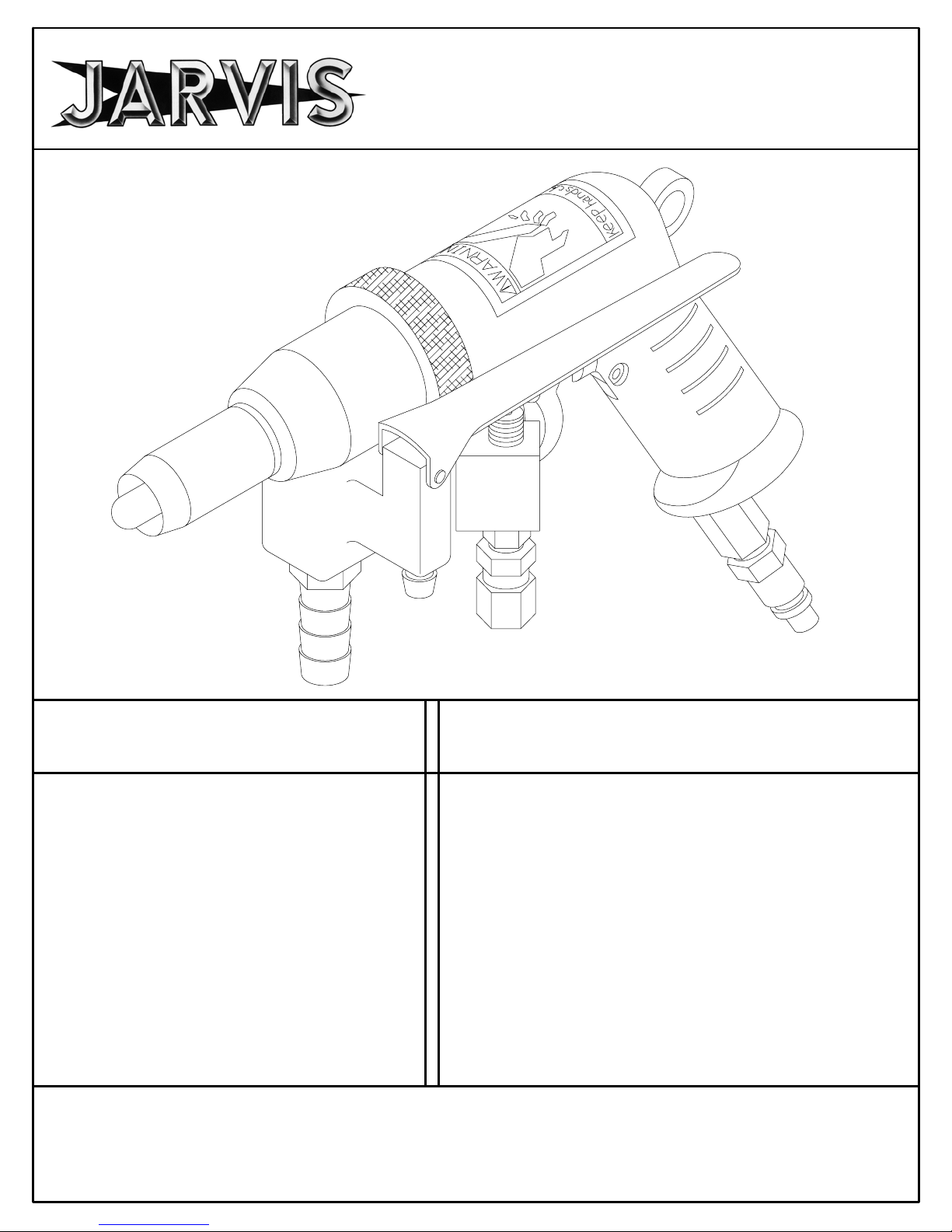
Model VC
Poultry Vent Cutter
EQUIPMENT
SELECTION Ordering No.
Model VC Package 4302008...........
Model VC 4302007...............
Balancer 1350084................
Air Control Circuit 3350006........
Vacuum Hose (8 ft.) 1323010......
Air Hose Assembly 1323011.......
Water Tube (8 ft.) 1323019........
Grease (1 lb.) 1348001............
Oil (1 pt.) 1348004................
JARVIS
6222009::.
..........
®
TABLE OF
CONTENTS Page.........................
• Notice to Employer and Safety
Director 2.........................
• Notice to Operators, Maintenance
and Cleanup Personnel 3............
• Parts Diagram and List 4............
• Installation Instructions 6............
• Specifications 7....................
• Operation Instructions 8.............
• Blade / Pilot Pin Information 9........
• Maintenance Instructions 10.........
• Troubleshooting 12.................
PRODUCTS CORPORATION
33 ANDERSON ROAD, MIDDLETOWN, CONNECTICUT 06457--4926
UNITED STATES OF AMERICA E--MAIL. jarvis.products.corp@snet.net
TEL. 860--347--7271 FAX. 860--347--6978
WWW
.jarvisproducts.com
Page 2

Model VC
noticetoemployer
and safety director
page 2 of 12
Keep hands clear
NOTICE TO EMPLOYER AND SAFETY DIRECTOR
AVOID INJURY
1. Remove and repair any tool that malfunctions. All personnel must be instructed to remove any
malfunctioning tool.
2. Ensure that all employees who use this tool are trained in the proper use of this tool and are aware of
the dangers that may arise if they do not follow the procedures outlined in this brochure.
3. Ensure that all employees who use this tool wear a steel mesh glove at all times. Do not rely on the
steel mesh glove for safety; employees who use this tool must be instructed to keep their free hand(s)
away from the cutting edge and the cutting path of the tool.
4. Enclosed are four (4) copies of “NOTICE TO OPERATORS, MAINTENANCE AND CLEANUP
PERSONNEL.” Post one copy on the employees’ bulletin board; give one copy to the operator(s);
give one copy to the maintenance foreman; and give one copy to the sub-contract / internal cleanup
foreman. Additional copies will be provided upon request.
5. The tool is designed and intended to be powerful. This fact should be obvious to your employees, but
you must emphasize it to them.
6. Never make modifications or alterations to the tool. Replace any missing or illegible labels.
7. Ensure that proper procedures are established (in accordance with OSHA’s lockout/tagout procedures
29 CFR 1910.147) to prevent accidental startup or release of stored energy.
8. Hand/Wrist/Arm injury and other Cumulative Trauma Disorders may result from repetitive work,
motion or vibration. You must make your employees aware of hazards, symptoms of injury and appropriate prevention. See OSHA’s “Ergonomics Program Management Guidelines for Meatpacking
Plants.”
9. Follow our installation and maintenance instructions for proper installation and care of the tool.
10. Avoid injury. Do not permit the tool to be misused.
11. If you resell or distribute a Jarvis product, you must provide the purchaser with the appropriate safety
sheets and tool brochure. Additional copies of safety sheets and tool brochures will be provided upon
request.
JARVIS
6222009::.
®
PRODUCTS CORPORATION
33 ANDERSON ROAD, MIDDLETOWN, CONNECTICUT 06457-- 4926
UNITED STATES OF AMERICA E--MAIL. jarvis.products.corp@snet.net
TEL. 860--347--7271 FAX. 860--347--6978 WWW.jarvisproducts.com
Page 3

notice to operators, maintenance
and cleanup personnel
page 3 of 12
Model VC
Keep hands clear
NOTICE TO OPERATORS, MAINTENANCE AND CLEANUP PERSONNEL
REMOVE ANY MALFUNCTIONING TOOL FROM SERVICE
REPORT ANY PROBLEMS TO YOUR SUPERVISOR
1. Disconnect the air supply in accordance with OSHA’s lockout/tagout procedures (29 CFR 1910.147)
before changing the blade.
2. Disconnect the air supply in accordance with OSHA’s lockout/tagout procedures (29 CFR 1910.147)
before performing any repairs or maintenance.
3. Disconnect the air supply -- or have the air supply disconnected -- in accordance with OSHA’s lockout/
tagout procedures (29 CFR 1910.147) before performing any cleanup.
4. Disconnect the air hose when the tool is not in use.
5. Never put fingers, hands or other parts of the body on the cutting edge of the blade or in the cutting path
of the tool.
6. Always wear a steel mesh glove on the hand that is not
gloves when handling the blade.
7. Test the tool prior to use or daily. Pull the trigger and the t ool should
tool should stop. If the tool malfunctions, remove it from service and report or repair it immediately.
8. Never depress the trigger unless you want to use the tool.
9. Never make modifications or alterations to the tool. Report or replace any missing or illegible labels.
operating the tool. Always wear steel mesh
start; release the trigger and the
JARVIS
6222009::.
®
PRODUCTS CORPORATION
33 ANDERSON ROAD, MIDDLETOWN, CONNECTICUT 06457-- 4926
UNITED STATES OF AMERICA E--MAIL. jarvis.products.corp@snet.net
TEL. 860--347--7271 FAX. 860--347--6978 WWW.jarvisproducts.com
Page 4

Model VC
*
see page 9 for
additional blade and
pilot pin information.
parts diagram and list
page 4 of 12
Model VC
Figure A
ITEM PART NO. PART NAME QTY
1 1327038
2 3332001
3 1312043 Cutter Shaft 1
4 3330007 Shaft Housing Assembly 1
5 1324040 Hose Connector 1
6 1343004 O--ring 2
7 1350032 Throttle Lever 1
8 1324033 Close Pipe Nipple 1
9 1350033 Lever Pivot Pin 1
10 1324061 Tube Connector w/Washer 1
11 3327002 Trigger Pin Assembly 1
12 1346001 Water Valve 1
13 1324066 Tube Connector 1
14 1350066 Grease Fitting 2
15 1311019 Needle Bearing 2
16 1342003 Planetary Gear 2
17 1350042 Rotor Vane 4
18 1304035 Motor End Plate (Rear) 1
19 131 1020 Ball Bearing 1
20 1301060 Screw 1
21 1017084 Warning Label 1
3
/8inch Pilot Pin 1
7
/8inch Blade 1
* use tool 8327001 to remove
ITEM PART NO. PART NAME QTY
22 1330042 Pistol Grip Handle 1
(includes items 20--23)
23 1317010 Hanger Ring 1
24 1327062 Trigger Retaining Pin 1
25 1343022 Gasket Seal 1
26 1303022 Split Lock Washer 2
27 1350081 Air Exhaust Muffler 1
28 1350043 Air Screen 1
29 1301092 Socket Head Cap Screw 2
30 1317012 Retaining Ring 1
31 1324017 Quick Connect Coupling 1
32 1350080 Air Inlet Valve 1
33 1327064 Valve Stem Pin 1
34 1327063 Valve Pin 1
35 1327048 Cam Retaining Pin 1
36 1349001 Trigger Cam 1
37 1338017 Trigger Bushing 1
38 1345005 Air Motor Trigger 1
39 1327046 Rotor Housing Pin 1
40 1337018 Rotor Sleeve 1
41 1312044 Splined Rotor 1
42 1304034 Motor End Plate (Front) 1
43 131 1021 Ball Bearing 1
44 1303019 Washer 1
45 1311018 Needle Bearing 1
46 1312045 Gear Shaft 1
47 1327047 Planetary Gear Pin 2
48 1342004 Ring Gear 1
49 131 1017 Ball Bearing 1
50 1316037 Shaft Spacer 1
JARVIS
6222009::.
®
PRODUCTS CORPORATION
33 ANDERSON ROAD, MIDDLETOWN, CONNECTICUT 06457-- 4926
UNITED STATES OF AMERICA E--MAIL. jarvis.products.corp@snet.net
TEL. 860--347--7271 FAX. 860--347--6978 WWW.jarvisproducts.com
Page 5

parts diagram and list
page 5 of 12
Air Control Circuit
Figure B
Model VC
ITEM PART NO. PART NAME QTY
51 1324069 Tube Connector 1
52 1324058 Tube Connector 4
53 3350002 Venturi Assembly 1
54 1324063 Reducer Bushing 2
55 1323012 Tubing (9 inch) 2
56 1324051 Street Elbow 3
57 1324049 Hex Pipe Nipple 6
58 1350063 Air Regulator 1
59 1350079 Air Pilot Valve 1
60 1324050 Pipe Tee 2
61 1350048 Air Pressure Gauge 1
62 1350067 Air Regulator 1
63 1324039 Hex Soc Pipe Plug 1
64 1350050 Air Filter 1
65 1350078 Air Pilot Valve 1
66 1346007 Check Valve 1
67 1350057 Air Lubricator 1
1323015 Trigger Control Hose ft
3343009 Seal Kit for item 59
JARVIS
6222009::.
®
PRODUCTS CORPORATION
33 ANDERSON ROAD, MIDDLETOWN, CONNECTICUT 06457-- 4926
UNITED STATES OF AMERICA E--MAIL. jarvis.products.corp@snet.net
TEL. 860--347--7271 FAX. 860--347--6978 WWW.jarvisproducts.com
Page 6
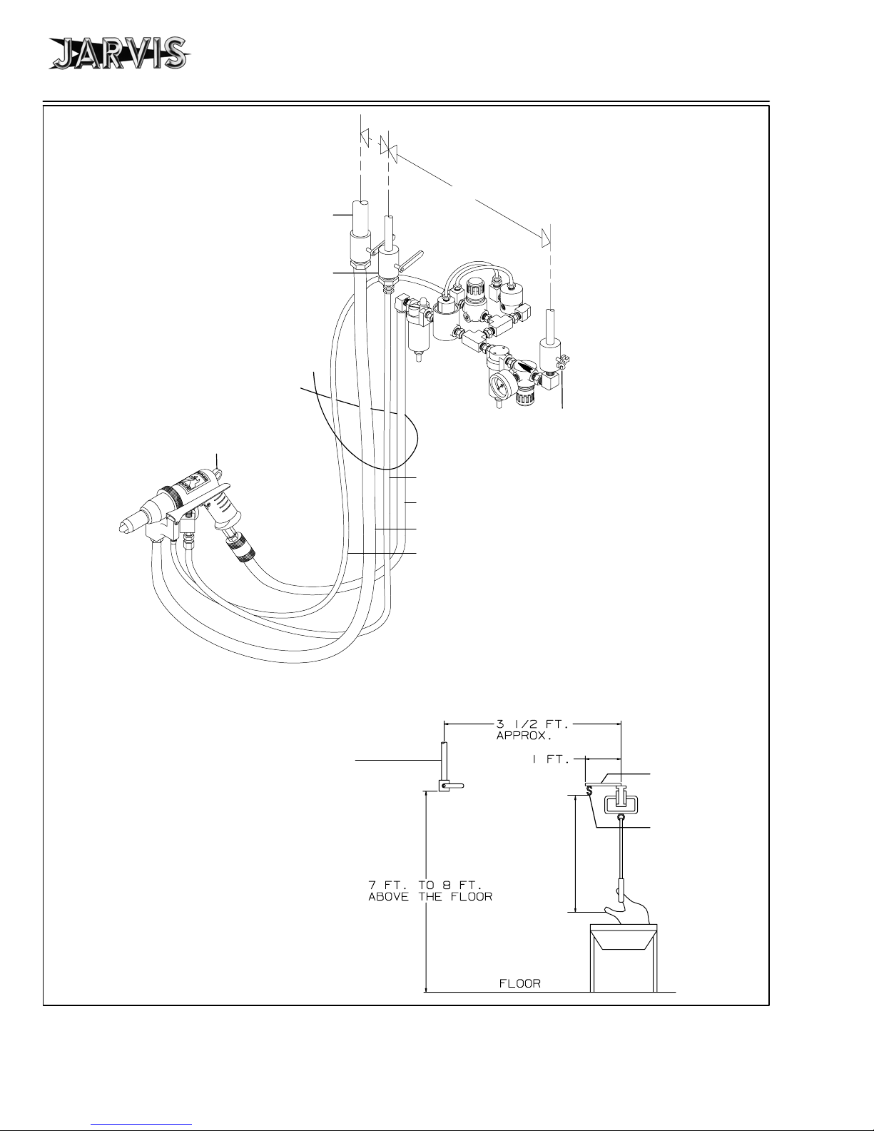
Model VC
Figure C
Model VC
To Vacuum Tank:
1
/2inch Pipe min.
1
1
/4Turn Shutoff Valve
To Water Supply:
1
/2inch Pipe
1
/4Turn Shutoff Valve
Tie all tubes and
hoses together.
To Balancer
3--6 inch
15 inch
Approx.
To compressed
air supply:
1
/2inch Pipe
Water Tube (1323019)
Air Hose (1323011)
installation instructions
page 6 of 12
Air Control Circuit
The vacuum pipe,
water pipe, air pipe
should all end at the
same height from
the floor.
Vacuum Hose (1323010)
Trigger Control Hose (1323015)
Figure D
The tool
should be
suspended
at this level.
Weld angle or
pipe to rail.
Weld “s” hook
to angle or pipe.
Hang tool balancer from “s”
hook.
Trough
JARVIS
6222009::.
®
PRODUCTS CORPORATION
33 ANDERSON ROAD, MIDDLETOWN, CONNECTICUT 06457-- 4926
UNITED STATES OF AMERICA E--MAIL. jarvis.products.corp@snet.net
TEL. 860--347--7271 FAX. 860--347--6978 WWW.jarvisproducts.com
Page 7

installation instructions
and specifications
page 7 of 12
Model VC
Model VC
SPECIFICATIONS
Operating Pressure 30-60 p si 2.0-4.1 bar
Air Consumption 5.6-14 ft3/min 0.16--0.39 m3/min
Vacuum Requirements 15 in Hg 50.8 kPa
Air Flow(vacuum) 6--7 ft3/min 0.16--0.19 m3/min
Capacity Limited by operator skill (avg. 3000 / hour)
INSTALLATION INSTRUCTIONS
1 Make a bracket to suspend the Model VC and ba-
lancer. Refer to Figure D, page 6.
2 Install a balancer (1350084) from the bracket. Refer
to Figures C and D, page 6.
3 Suspend the Model VC from a balancer (1350084).
Refer to Figures C and D, page 6.
4 Make the necessary vacuum connection. Refer to
Figures C and D, page 6.
Control Handle Single Trigger
Blade Dia. (range) 0.75--1.75 in 19--44 mm
Blade Length (range) 0.88--3.50 in 22--89 mm
Overall Length 11.0 in 267 mm
Weight 3.2 lbs 1.45 kg
7.1.1 Attach the 8 ft. v acuum hose (1323010) to
the vacuum supply.
7.1.2 Attach the 8 ft. v acuum hose (1323010) to
connector (item 5).
7.2 Water:
7.2.1 Attach the 8 ft. water tube (1323019) to the
water supply.
5 Make the necessary water connection. Refer to Fig-
ures C and D, page 6.
6 Make the necessary air connection. Refer to Figures
C and D, page 6.
6.1 The air control circuit (3350006) must be installed in the air supply line.
6.1.1 The required compressed air supply is 14
7 Model VC hook--up. Refer to Figure C, page 6. Re-
fer to pages 4 and 5 for all referenced items.
7.1 Vacuum:
3
ft
/min at 60 psi.
7.2.2 Attach the 8 ft. water tube (1323019) to connector assembly (item 13).
7.3 Air:
7.3.1 Attach the air hose (1323011) to street elbow (item 56).
7.3.2 Attach the air hose (1323011) to quick connect coupling (item 31).
7.3.3 Attach trigger control hose (1323015) to
tube connector (item 51).
7.3.4 Attach trigger control hose (1323015) to
tube connector (item 10).
JARVIS
6222009::.
®
PRODUCTS CORPORATION
33 ANDERSON ROAD, MIDDLETOWN, CONNECTICUT 06457-- 4926
UNITED STATES OF AMERICA E--MAIL. jarvis.products.corp@snet.net
TEL. 860--347--7271 FAX. 860--347--6978 WWW.jarvisproducts.com
Page 8

Model VC
operation instructions
page 8 of 12
OPERATION INSTRUCTIONS
IMPORTANT: DISCONNECT THE AIR LINE IN ACCOR-
DANCE WITH OSHA’S LOCKOUT/TAGOUT PROCEDURES
(29 CFR 1910.147) BEFORE SHARPENING BLADES. DIS-
CONNECT THE AIR LINE IN ACCORDANCE WITH OSHA’S
LOCKOUT/TAGOUT PROCEDURES (29 CFR 1910.147) BE-
FORE PERFORMING ANY REPAIR OR MAINTENANCE.
Refer to pages 4 and 5 for all referenced items.
1 Attach the 8 ft. vacuum hose (1323010) to connector
(item 5).
2 Attach the 8 ft. water tube (1323019) to connector
assembly (item 13).
3 Attach the air hose (1323011) to quick connect cou-
pling (item 31).
4 Attach trigger control hose (1323015) to tube con-
nector (item 10).
5 Each day, before you begin operation, go through
the following checklist:
5.1 Make sure that the Model VC moves freely on
its balancer.
5.2 Make sure that you are wearing a steel mesh
safety glove on the hand that will not be operating the Model VC.
6.2 With the vacuum activated, insert the pilot pin
(item 1) into the anus of the bird. The entire anus
ring should be enclosed by the blade, and the
skin of the bird should be sucked up around the
entire cutting edge of the blade. Refer to Figure
2.
Anus
Blade
Pilot pin
Rosebud
gland
Tail
Oil gland
Anus ring
Backbone
Figure 2
6.3 While vacuum is holding the skin upward, pull
the trigger back fully and allow the blade to rotate. Move the blade gently forward into the bird
about 1/2 to 3/4 of the length of the blade. Do
not apply pressure on the bird until the blade is
rotating. Refer to Figures 3 and 4.
Proper Method
Skin is pulled up by
vacuum against the
cutting edge of the blade.
6 Making the cut:
6.1 Pull the trigger until it touches the round trigger
on the motor. This activates the vacuum at the
blade. Refer to Figure 1.
Round motor
trigger
Trigger in
rest position
JARVIS
6222009::.
Figure 1
Trigger in
activated
position
®
Rosebud gland
is inside of the
blade.
Improper Method
Rosebud gland
is outside of the
blade.
Figure 3
Skin is depressed
before the blade is
activated.
Figure 4
PRODUCTS CORPORATION
33 ANDERSON ROAD, MIDDLETOWN, CONNECTICUT 06457-- 4926
UNITED STATES OF AMERICA E--MAIL. jarvis.products.corp@snet.net
TEL. 860--347--7271 FAX. 860--347--6978 WWW.jarvisproducts.com
Page 9
operation instructions
and blade/pilot pin information
page 9 of 12
6.4 A gentle motion with a downward pressure will
cut the bird properly. Forcing the blade will
leave all or part of the rosebud in the bird.
not
force the blade or stab the bird with the
blade. Do not
pressing it. The blade will turn only a few revolutions and will shut off automatically (it will
not cut the intestines). The vacuum will remain
sucking as long as the trigger is held in the fully
depressed position.
6.5 The blade must always be angled toward the
center of the bird. If the blade is directed toward
either side, it will leave solid muscle attached to
the vent and this material cannot be broken loose
by hand.
6.6 While still holding the trigger, pull the blade
slowly out of the bird. The vacuum will hold the
anus and the fecal material long enough for the
operator to either grab the vent and move it away
from the hole or to move the vent away from the
hole with the gun.
6.7 Release the trigger. The vacuum will shutoff
and release the vent into the operators hand so
that it can be pulled out of the carcass and laid
gently over the side of the carcass or it will release the vent over the side of the carcass if the
vacuum pulls the vent completely out of the carcass.
6.8 After releasing the vent, the operator must aim
the blade at the trough before reaching the next
bird. Depress the water flush lever to flush out
all materials from the blade before attempting to
cut another bird. Do not
the birds. The water will not flush out the blade
unless the vacuum trigger is in the rest position.
When both vacuum and water triggers are activated, all water will be sucked up the vacuum
tube sending all waste material to the collector
tank.
let g o of the trigger after fully de-
flush waste material on
Model VC
Do
BLADE INFORMATION (inches)
PART N O . DIAMETER LENGTH
3332001 7/8 15/8
3332002 3/4 15/8
3332003 1 2
3332004 11/4 2
3332005 11/2 2
3332006 7/8 21/2
3332008 11/8 31/2
3332009 11/4 31/2
3332010 13/8 31/2
3332011 11/2 31/2
3332015 11/8 2
3332016 13/8 2
3332026 13/4 23/4
PILOT PIN INFORMATION (inches)
PART N O . DIAMETER LENGTH
1327038 3/8 2
1327040 1/2 21/2
1327041 5/16 2
1327052 1/2 31/4
1327053 3/8 23/4
1327054 3/8 21/2
1327057 3/8 33/4
6.9 When a bird has fecal material on the outside of
the carcass, it can be washed off with the vent
gun before cutting the bird. Be sure that the
blade has been sufficiently flushed into the
trough before attempting to wash off any bird.
Do not
the carcass.
JARVIS
6222009::.
attempt to wash the bird after cutting into
®
PRODUCTS CORPORATION
33 ANDERSON ROAD, MIDDLETOWN, CONNECTICUT 06457-- 4926
UNITED STATES OF AMERICA E--MAIL. jarvis.products.corp@snet.net
TEL. 860--347--7271 FAX. 860--347--6978 WWW.jarvisproducts.com
Page 10

Model VC
maintenance instructions
page 10 of 12
MAINTENANCE INSTRUCTIONS
IMPORTANT: DISCONNECT THE AIR LINE IN ACCOR-
DANCE WITH OSHA’S LOCKOUT/TAGOUT PROCEDURES
(29 CFR 1910.147) BEFORE PERFORMING ANY REPAIR OR
MAINTENANCE.
Refer to pages 4 and 5 for all referenced items.
1 DAILY:
1.1 Check to see that the Model VC is getting
enough lubrication. Each one or two pulls of the
trigger should produce one drop of oil in the
sight dome. If required, adjust the oil flow.
1.2 Make sure that the oil in the lubricator is up to
the full mark. Use USDA approved Jarvis Air
Mist Lubricator Oil. Do not use mineral oil.
2 WEEKLY:
2.1 Add four to five shots of grease to grease fitting
(item 14). Use USDA approved Jarvis 1315
White Grease.
material and make it impossible to hold a
sharp edge. Return to Jarvis for regrinding.
4 MODEL VC BLADE DISASSEMBLY:
Wear cut protective gloves when handling blades.
4.1 While holding base of blade (item 2) in place,
use special wrench (part number 8327001) to
loosen pilot pin (item 1).
4.2 Remove blade (item 2).
4.3 Inspect blade (item 2) for wear and sharpen if
necessary.
5 MODEL VC BLADE ASSEMBLY:
Wear cut protective gloves when handling blades.
5.1 Place blade (item 2) over cutter shaft (item 3).
5.2 Assemble pilot pin (item 1) through blade (item
2).
3 WHEN NECESSARY:
Wear cut protective gloves when handling blades.
3.1 Sharpen the blade (item 2) when the blade becomes difficult to push into the carcass, or when
the cutting produces contamination.
3.1.1 Place a sharpening stone on the cutting
angle of the blade and activate the tool.
Continue to desired sharpness. If this action
rolls the cutting edge inward, hold a small
steel on the inside edge of the blade.
3.1.2 Repeat the process until the blade is sharp.
3.1.3 If the angle of the blade becomes too short
or when the cutting edge has excessive
nicks, the blade must be reground. Do not
heat the cutting edge. Heat will anneal the
JARVIS
6222009::.
®
5.3 Tighten pilot pin (item 1) hand tight into cutter
shaft (item 3). The pilot pin will automatically
tighten with use of the tool.
6 MODEL VC DISASSEMBLY:
6.1 Follow steps and procedures 4.1 and 4.2.
6.2 Unscrew the knurled ring on shaft housing assembly (item 4).
6.3 Remove shaft housing assembly (item 4). Be
careful not to lose the trigger pin assembly (item
11).
6.4 Place a pin through the cross hole in the cutter
shaft (item 3) and hit pin with a hammer on the
proper end to turn it counter--clockwise.
WARNING: pin may fly out of unit. Protect
yourself and other employees when disassembling this part.
PRODUCTS CORPORATION
33 ANDERSON ROAD, MIDDLETOWN, CONNECTICUT 06457-- 4926
UNITED STATES OF AMERICA E--MAIL. jarvis.products.corp@snet.net
TEL. 860--347--7271 FAX. 860--347--6978 WWW.jarvisproducts.com
Page 11

maintenance instructions
page 11 of 12
Model VC
6.5 Remove the cutter shaft (item 3).
6.6 Place the Model VC in a soft jaw vise (apply
pressure only to the handle) and unscrew ring
gear (item 48).
6.7 Remove the ring gear (item 48).
6.8 Remove the gear shaft assembly (items 15--16,
45--47).
6.9 Tap on the front of pistol grip handle (item 22)
with a soft hammer (plastic lead, wood) to dislodge the motor assembly (items 17--19, 39--43).
6.10 Remove the motor assembly (items 17--19,
39--43). Do not lose rotor housing pin (item 39).
6.11 Inspect all parts for wear and replace if necessary.
7 MODEL VC ASSEMBLY:
8.5 Inspect all parts for wear and replace if necessary.
9 GEAR SHAFT ASSEMBLY:
9.1 Press needle bearing (item 45) into gear shaft
(item 46).
9.2 Insert needle bearings (item 15) into planetary
gears (item 16).
9.3 Place bearing and gear assembly (items 15 and
16) into gear shaft (item 46) making sure that
bearing hole and gear pin hole are aligned.
9.4 Press planetary gear pins (item 47) into the
threaded end of gear shaft (item 46).
10 MOTOR DISASSEMBLY:
10.1 Hold front motor end plate (item 42) while tapping on the splined end of the splined rotor (item
41) with a soft hammer (plastic, lead, wood).
7.1 Reverse steps and procedures outlined in steps
6.1--6.10. See note below:
7.1.1 Install motor assembly with rotor housing
pin (item 39) in proper place.
8 GEAR SHAFT DISASSEMBLY:
8.1 Press out planetary gear pin (item 47) from the
non--threaded end of gear shaft (item 46).
8.2 Remove planetary gear assemblies (items 15
and 16).
8.3 Push needle bearing (item 15) from planetary
gear (item 16).
8.4 Use bearing puller (part number 1350131). Insert nut into the center of g ear shaft (item 46).
Screw cap head screw into the nut until needle
bearing (item 45) is removed.
10.2 Remove the front motor end plate (item 42) and
ball bearing (item 43).
10.3 Slide off rotor sleeve (item 40).
10.4 Remove vanes (items 17).
10.5 Press splined rotor (item 41) from rear motor
end plate (item 18).
10.6 Press ball bearings (items 19 and 43) out of rear
motor end plate (item 18) and front motor end
plate (item 42).
10.7 Inspect all parts for wear and replace if necessary.
11 MOTOR ASSEMBLY:
11.1 Reverse steps and procedures outlined in steps
10.1--10.6.
JARVIS
6222009::.
®
PRODUCTS CORPORATION
33 ANDERSON ROAD, MIDDLETOWN, CONNECTICUT 06457-- 4926
UNITED STATES OF AMERICA E--MAIL. jarvis.products.corp@snet.net
TEL. 860--347--7271 FAX. 860--347--6978 WWW.jarvisproducts.com
Page 12

Model VC
gg,g(
)
TROUBLESHOOTING
REMOVE ANY MALFUNCTIONING TOOL FROM SERVICE
PROBLEM SOLUTION
MOTOR RUNS WHEN THE TRIGGER IS RELEASED.
Refer to page 4 for referenced items.
BLADE DOES NOT ROTATE AND SHUT OFF WHEN TRIGGER IS PULLED.
Refer to page 5 for referenced items.
BLADE DOES NOT ROTATE WHEN TRIGGER IS PULLED.
Refer to pages 4 and 5 for referenced items.
WATER VALVE LEAKS.
Refer to page 4 for referenced items.
troubleshooting
page 12 of 12
CHECK THE AIR MOTOR TRIGGER (ITEM 38).
If the trigger flops in and out or stays depressed when touched,
it is malfunctioning. Remove the air inlet valve (item 32) and
valve stem pin (item 33). With long nose pliers, remove valve
pin (item 34). Clean pins until their surfaces are smooth. Clean
out the deepest hole in the pistol grip handle (item 22) with a drill.
Rotate the drill by hand. Do not increase the size of the hole.
CHECK THE O--RING LOCATED IN AIR INLET VALVE (ITEM
32).
Remove the retaining ring, screen, spring, and poppet from the
air inlet valve (item 32). Check for an o--ring on the poppet. If
there is no o--ring on the poppet, check the inside of the air inlet
valve. Reassemble the o--ring to the poppet and reassemble the
air inlet valve.
ADJUST AIR REGULATOR (ITEM 58).
Pull trigger on Model VC, and turn air regulator knob (item 58)
clockwise until the blade on the vent gun turns off. Continue to
adjust until desired number of blade rotations is accomplished.
CHECK AIR PILOT VALVE (ITEM 59).
Remove four screws and cover on air pilot valve (item 59) carefully. Check rubber diaphragm. If the rubber diaphragm has a
hole, it must be replaced (part number 3343009).
CLEAN VENTURI ASSEMBLY (ITEM 53).
If the regulator has no range of adjustment, clean the venturi assembly. Remove tube connector (item 52). Clear the small hole
in the silver pin with a small diameter wire. Do not increase the
size of the hole.
CHECK THE AIR SUPPLY.
The air pressure gage (item 61) must show pressure.
CHECK THE VACUUM.
When trigger is pulled, there is suction at the blade. If there is
no suction at the blade, the air supply to the tool is shut off.
CHECK VANES (ITEM 17).
If air is exhausting through the butt of the pistol grip handle, release trigger and turn blade 1/2 revolution. Pull trigger. If the
Model VC runs properly now, it is an indication of sticky vanes
(causes: wrong oil, dirt in slots, lack of oil). Disassemble motor,
clean rotor, and check length of vanes (they should be .002
shorter than the length of the rotor). Check rotation of each bearing (they should rotate freely).
WATER VALVE LEAKS AT TIME OF INSTALLATION.
Check for metal fragments from the threaded pipe. Remove water tube from tube connector (item 13). Remove tube connector
(item 13). Check water valve (item 12) for debris, and remove
debris with small pointed object. Do not damage spring or seal.
WATER VALVE LEAKS AFTER CONSIDERABLE USE.
Replace water valve (item 12).
JARVIS
6222009::.
®
PRODUCTS CORPORATION
33 ANDERSON ROAD, MIDDLETOWN, CONNECTICUT 06457-- 4926
UNITED STATES OF AMERICA E--MAIL. jarvis.products.corp@snet.net
TEL. 860--347--7271 FAX. 860--347--6978 WWW.jarvisproducts.com
 Loading...