


Model
SEC 180
Circular Breaking Saw
EQUIPMENT
SELECTION Ordering No.
Model SEC 180 Non–Indexing Depth Gage
Internal Brake
220 V 4004049.
115
External Brake
42 V 4004047.
Model SEC 180 Indexing Depth Gage
Internal Brake
220 V 4004085.
115
External Brake
220 V 4004134.
115
42
V
Model SEC 180 Dual Trigger & External Brake
220 V 4004094.
115
42
V
Balancer 4042002
. . . . . . . . . . . . . . . . . . . . . . . . .
JARVIS
6204012::.
.
. . . . . . . . .
. . . . . . . . . . . . . . . . . . . .
V
. . . . . . . . . . . . . . . . . . . .
. . . . . . . . . . . . . . . . . . . . .
. . . . . . . . . . . . . . . . . . . .
V
. . . . . . . . . . . . . . . . . . . .
. . . . . . . . . . . . . . . . . . . .
V
. . . . . . . . . . . . . . . . . . . .
. . . . . . . . . . . . . . . . . . . . .
. . . . . . . . . . . . . . . . . . . .
V
. . . . . . . . . . . . . . . . . . . .
. . . . . . . . . . . . . . . . . . . . .
4004048.
4004104.
4004133.
4004122.
4004093.
4004092.
TABLE OF
CONTENTS Page.
• Notice to Employer and Safety
Director 2.
• Notice to Operators, Maintenance
and Cleanup Personnel 3.
• Parts Diagram and List 4.
• Special Tools 10.
• Specifications 11
• Installation Instructions 11.
• Operating Instructions 12.
• Maintenance Instructions 13.
PRODUCTS CORPORATION
33
ANDERSON ROAD, MIDDLET
UNITED STATES OF AMERICA
TEL. 860–347–7271 FAX. 860–347–6978
. . . . . . . . . . . . . . . . . . . . . . . . . . .
. . . . . . . . . . . . . . . . . . . . . . . . . . . . . . . .
. . . . . . . . . . . . . . . . . .
. . . . . . . . . . . . . . . . . . .
. . . . . . . . . . . . . . . . . . . . . . . . . .
. . . . . . . . . . . . . . . . . . . . . . . . . . .
. . . . . . . . . . . . . . . . . .
. . . . . . . . . . . . . . . . . . .
. . . . . . . . . . . . . . .
OWN, CONNECTICUT 06457–4926

Model SEC 180
notice to employer
and safety director
page 2 of 16
Keep hands clear
NOTICE T
1. Remove and
functioning equipment.
2. Ensure
the dangers that may arise if they do not follow procedures outlined in this brochure.
3. Ensure that all employees are instructed not to walk in front of the tool during its use.
4. Enclosed
PERSONNEL.” Post one copy on the employees’ bulletin board; give one copy to the operator(s);
give one copy to the maintenance foreman; and give one copy to the sub-contract cleanup / internal
cleanup foreman. Additional copies will be provided upon request.
5. The
6. Never make modifications or alterations to the tool. Replace any missing or illegible labels.
tool is designed and intended to be powerful. This fact should be obvious to
you must emphasize it to them.
repair
that all employees who use this tool are trained in the proper use of this tool and are aware of
are four (4) copies of
any tool that malfunctions.
O EMPLOYER AND SAFETY DIRECT
AVOID
“NOTICE TO OPERATORS, MAINTENANCE AND CLEANUP
INJUR
All personnel must be instructed to remove any mal
Y
.
OR
your employees, but
-
7. Ensure
(29 CFR 1910.147) to prevent accidental startup or release of stored energy.
8. Follow our installation and maintenance instructions for proper installation and care of the tool.
9. Avoid injury. Do not permit the tool to be misused.
10. If
sheets
request.
JARVIS
6204012::.
that proper procedures are established in accordance with OSHA’s lockout/tagout procedures
you
resell
or
distribute
and tool brochure.
a Jarvis product, you must provide the purchaser with the appropriate safety
Additional copies of
safety sheets and tool br
PRODUCTS CORPORATION
33
ANDERSON ROAD, MIDDLET
UNITED STATES OF AMERICA
TEL. 860–347–7271 FAX. 860–347–6978
ochur
OWN, CONNECTICUT 06457–4926
es will be pr
ovided upon

notice
to operators, maintenance
and cleanup personnel
page 3 of 16
Model SEC 180
Keep hands clear
NOTICE T
1. Disconnect the power supply in accordance with OSHA’s lockout/tagout procedures (29 CFR
1910.147) before making any blade changes.
2. Disconnect the power supply in accordance with OSHA’s lockout/tagout procedures (29 CFR
1910.147) before performing any repair or maintenance.
3. Disconnect
lockout/tagout procedures (29 CFR 1910.147) before performing any cleanup.
4. Disconnect the power supply when the tool is not being used.
5. Never
tool.
6. Never allow people to walk in front of the tool during its use.
7. Never allow people to hold / restrain the carcass while operating the tool.
O OPERATORS, MAINTENANCE AND CLEANUP PERSONNEL
REMOVE ANY MALFUNCTIONING T
REPORT ANY PROBLEMS TO YOUR SUPERVISOR
the power supply - or have the power supply disconnected - in accordance with OSHA’s
put fingers, hands or other parts of the body on the cutting edge
.
OOL FROM SER
or within the cutting path of the
VICE
8. Test
9. Test
10. Never depress the trigger unless you want to use or test the tool.
11. Never
12. Always
JARVIS
6204012::.
the
tool
prior to use or daily
Release
and the tool should not
either
repair it immediately.
2.5 seconds. If the tool malfunctions, remove it from service and r
or “recoil.” Continue holding the tool with both hands until the saw blade comes to a complete stop.
the trigger and the tool should
start.
trigger and the tool should
the
brake
make modifications or alterations to the tool.
use both hands when starting and operating the tool to avoid the risk of possible “kick back”
prior to use or daily
. For
single trigger tools:
stop. For dual trigger tools:
Depress
both
triggers simultaneously and the tool should
stop.
If the
tool malfunctions, r
. After releasing either or both triggers, the tool should stop within
PRODUCTS CORPORATION
33
ANDERSON ROAD, MIDDLET
UNITED STATES OF AMERICA
TEL. 860–347–7271 FAX. 860–347–6978
Depr
Report or r
ess
the trigger and the tool should
Depress
emove it from service and r
eport or r
eplace
OWN, CONNECTICUT 06457–4926
each
trigger
epair it immediately.
any missing or illegible labels.
individually
start.
start.
Release
eport or
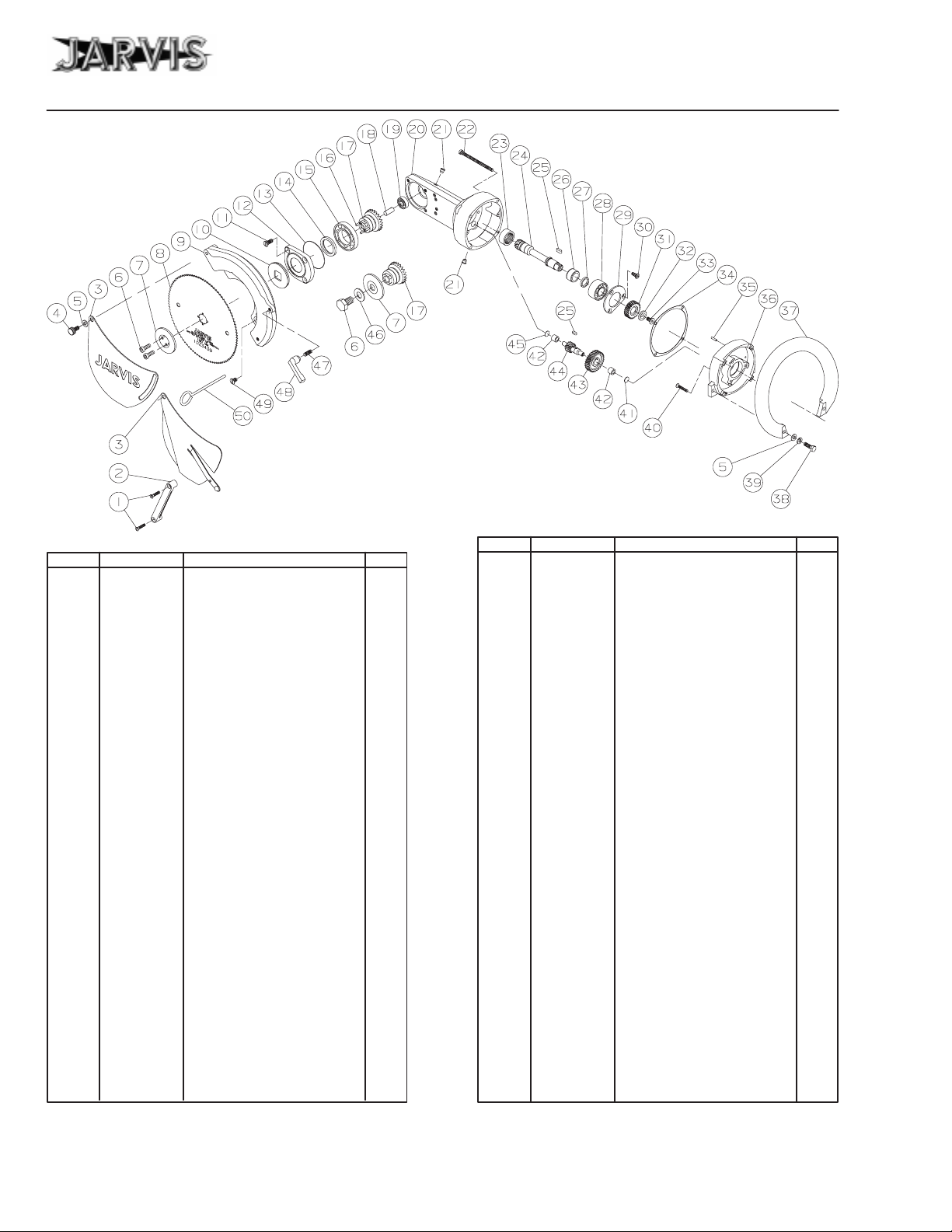
parts diagram and list
Model SEC 180
**
*
*
ITEM PART NO. PART NAME QTY
1 1055901 Oval Head Screw 2
2 1033013 Index Block 1
3 3025011 Depth Gage Assy
1025031
4 1054172 Thumb Screw 1
1055609* Hex Screw
5 1004286* Washer 2
1036222*
6 1055964**
1054139*
7 1004317
1004252*
8 1023439
1023440
1023272*
1023332*
9 1024144
1024169
10 1004258 Slinger 1
11 1055835
12 1002327 Gear Housing Cover 1
13 1035416 O–ring 1
14 1035460
15 1021359
16 1010452
1010446*
17 1026197 Crown Gear with Pins 1
1026192* Crown Gear without Pins
1026158* Crown Gear (one screw) 1
18 1020355
19 1021351
20 3016279 Gear Housing (incls. items 1
21 1038006
Depth Gage, Non–index
Bushing (not shown)
Blade Retaining Screw
Blade Retaining Screw
Blade Retaining W
Blade Retaining W
Saw Blade, 98 T
Saw Blade, 48 T
(with Round Hub and Pins)
Saw Blade, 98 T
Saw Blade, 48 T
(with Square Hub*)
Blade Guard, Non–index
Saw Blade Guard, Index
Flat Head Slotted Screw
Shaft Seal
Ball Bearing
Dowel Pin (with item 17)
Dowel Pin
Gear Shaft (with item 17)
Ball Bearing
21, 23, 42 and 45)
Grease Fitting
* Not used in current tools
For indexing models only
** W
rench 8039146 is provided
For non–indexing models only
, Index
asher 1
asher 1
eeth
eeth
eeth 1
eeth
page 4 of 16
Figure A
*
*
*
ITEM PART NO. PART NAME QTY
22 1055854 Cheese Head Screw 4
23 1021360
24 1026157
1
2
1
1
3
1
1
4
1
1
2
25 1030061 Key 2
26 1021361
27 1029310 Spacer 1
28 1021155
29 1004255
30 1055781 Oval Head Screw 3
31 1026156 Helical Gear 1
32 1004253 Washer 1
33 1055852 Flat Head Socket Screw 1
34 1035468 Gear Housing Gasket 1
35 1010366
36 3002034 Front Motor Cover Assy. 1
37 1019142
38 1055613 Hex Head Screw 6
39 1004231 Split Lock Washer 2
40 1055856 Oval Head Screw 3
41 1004363 Thrust Washer 1
42 1021362
43 1026154 Helical Gear 1
44 1026155 Helical Gear 1
45 1004364 Thrust Washer
1004254* Thrust Washer
46 1014159* Locking Washer 1
47 1027060 Stud 1
48 1006047
49 1055873
50 8039099
3026064
3026060* Two Screws w/o Pins Arbor
3026051* One Screw Arbor
3026052
Needle Bearing
Spiral Bevel Pinion Gear
Needle Bearing Race
Ball Bearing
Bearing Retaining W
Dowel Pin
(incls. items 35, 41 and 42)
Front Handle
Needle Bearing
Gage Locking Lever
Flat Head Slotted Screw
Blade Locking Pin
Spiral Bevel Gear Set
(incl. items 16–18, 24 & 26)
Helical Change Gear Set
(incls. items 25, 31 and 44)
asher 1
, .15 thick
, .03 thick
1
1
1
1
1
1
2
1
1
2
1
1
JARVIS
6204012::.
PRODUCTS CORPORATION
33
ANDERSON ROAD, MIDDLET
UNITED STATES OF AMERICA
TEL. 860–347–7271 FAX. 860–347–6978
OWN, CONNECTICUT 06457–4926

parts diagram and list
page 5 of 16
Model SEC 180
V
Used on internal brake models only
G
Used on external brake models only
♦
Used on models with single cord connections only
Y
Used on models with dual cord connections only
ITEM PART NO. PART NAME QTY
51 3026053 Helical Pinion Gear Assy 1
52 1029309
53 1013150
54 1021363
55 1004297 Washer 1
56 1004256
57 1061560 Fan 1
58 3063100 Armature Assembly
59 1021364
60 1055855 Cheese Head Screw 2
61 1016391
62 1063470 Stator
63 1036197
64 3016281
65 1002326 Brush Cover 2
66 1047012
67 1061559 Brush Holder 2
68 1007296 Hex Nut 4
69 1002330 Rear Motor Cover 1
70 1055914 Hex Head Screw 2
71 1055716 Hex Head Screw 1
72 1024172 T
73 1055895 Pan Head Screw 4
74 1017188
75 1055725 Pan Head Screw 4
76 1035469 Rear Handle Gasket 1
77 1042281
78 1014085 Spring 1
79 1019188
See parts lis
3063194 Armature Assembly
3063195 Armature Assembly
1063801 Stator
1063802 Stator
1047010
1047008
1019141G
1019164G
t on page 6 for part n
(incl. items 25, 43, 52 & 53)
Helical Pinion Spacer
Retaining Ring
Ball Bearing
Bearing Retaining W
(includes items 57 and 59)
Ball Bearing
Fan Housing
, 42 V
, 1
15 V
, 220 V
Motor Housing Bushing
Motor Housing (includes
items 63 and 67)
Motor Brush, 42 V
Motor Brush, 1
Motor Brush, 220 V
rigger Guard
Label Plate
Hanger Bkt. (incl. item 109)
Rear Handle with Brake
Rear Handle A
Rear Handle 42 V
umbers t
, 42 V
, 1
, 220 V
15 V
TD
o i
asher 1
15 V
tems 80–109.
1
1
1
1
1
1
1
1
1
1
1
1
1
2
2
2
1
1
1
1
Figure B
Y
Y
Y
Y
G
G
Y
♦
V
V
JARVIS
6204012::.
PRODUCTS CORPORATION
33
ANDERSON ROAD, MIDDLET
UNITED STATES OF AMERICA
TEL. 860–347–7271 FAX. 860–347–6978
OWN, CONNECTICUT 06457–4926

Model SEC 180
Figure C
Anti–tie Down
Handle Assembly
parts diagram and list
page 6 of 16
V
Used on internal brake models only
G
Used on external brake models only
♦
Used on models with single cord connections only
Y
Used on models with dual cord connections only
See Figure B on page 5 for items 80–109.
ITEM PART NO. PART NAME QTY
80 1055913 Self Tapping Screw
81 1010167
82 1018126
83 1010356
84 1042373
1042282
85 1055834 Pan Head Screw 1
86 1005126
1005104
87 1004257
88 1013220
89 1035414 Handle Cover Gasket 1
90 1002329♦
1002339
1002370Y
91 1017083
92 1011260 Connector
1011328 Connector
93 1001099
1001039 Electric Cord, 42 V
1001081V
94 1063560G
Roll Pin
Switch Actuating Lever
Dowel Pin
V Switch Holder for Brake 1
G Switch Holder
V Electric Switch for Brake 2
G Electric Switch
Ring W
asher 1
Retaining Ring
Handle Cover (incl. item 91)
Y
Handle Cover
Handle Cover
Danger Label
Spiral Cord, 1
Spiral Cord for brake
Rubber Grommet
, 1
15V & 220V
, 42 V
, 1
15 V & 220 V
, 42 V
15 V & 220 V
2
2
1
1
1
1
1
1
1
1
1
ITEM PART NO. PART NAME QTY
95 1063505G
96 1063549
97 1063209
98 1001100
99 1011279
100 1055832 Oval Head Screw 2
101 1035413
102 1063820
1063821
103 1029341
104 1055777 Cheese Head Screw 4
105 1029342 Hex Spacer 2
106 1018162 T
107 1010362
108 1055894 Socket Head Cap Screw 4
109 1036209
110 1044060
111 1014096 Spring 1
112 1018113 T
113 1010395
114 1019163
115 3005017 Switch Assembly 1
116 1035282 O–ring 1
117 1002367 Switch Cover 1
118 1042343 Handle Bracket 1
119 1011309
120 1001050 Electric Cord 1
121 1011310
122 1007303 Locking Nut 1
123 1055746 Socket Head Cap Screw 4
Plug 1
15 V and 220 V
Y
Rubber Grommet
Y
Signal Cord Plug
Y
Spiral Cord
Y Connector
Diaphragm Seal
V
Brake Board, 1
V
Brake Board, 220 V
V
Circuit Board Spacer 2
rigger Lever (incl. item 78)
Dowel Pin
Bushing (with item 77)
Handle Mounting Flange
rigger Lever
Threaded Pin
Front Handle
Strain Relief Connector
Strain Relief Connector
, 42 V and A
15 V
1
1
1
1
TD 1
1
1
1
1
1
2
1
1
2
1
1
1
JARVIS
6204012::.
PRODUCTS CORPORATION
33
ANDERSON ROAD, MIDDLET
UNITED STATES OF AMERICA
TEL. 860–347–7271 FAX. 860–347–6978
OWN, CONNECTICUT 06457–4926

parts diagram and list
page 7 of 16
Remote Electronic Brake
Single Trigger
3063121 (220V)
3063130 (1
Model SEC 180
Figure D
15V)
ITEM PART NO. PART NAME QTY
1
1016445 Electrical Enclosure 1
2
10
1
12
13
14
15
16
17
18
1063393 T
3
1032436
4
1063496 Y
5
1063455 Fuse T
6
1063542 Fuse 1
7
1063494 Gray T
8
1063363 T
9
1055803 Pan Head Screw 2
1004247 Washer 4
1
1011249
1007256 Locking Nut 2
1063362
1063723 Aux. Contact 1
1063089
1063722 Contactor
1063726 Contactor
1063079
1001188 Cord ft
erminal Rail
Mounting Plate
ellow/ Green T
erminal Block
erminal Block
erminal Marker
Cord Connector
End Clamp T
Wire Ring T
Wire Ring T
erminal 1
erminal 2
, 220 V
, 1
15 V
erminal 2
1
1
erm. Block 1
1
5
7
2
1
1
JARVIS
6204012::.
ITEM PART NO. PART NAME QTY
19
20
21
22
23
24
25
26
27
28
29
30
31
32
33
34
1061545 Ferrule 8
1042341 Resistor Bracket 2
1055779 Cheese Head Screw 2
1004241 Lock Washer 2
7800565
1063724 Power Resistor
1063727 Power Resistor
1063619 Brake Board 1
1029302 Spacer 4
1004244 Washer 4
1063725 Fuse 4
1055974 Pan Head Screw 2
1063533
1063506 Outlet 1
1063560 Grommet 1
1017085
1017237
1017238
Insulating T
Fem. Wire T
Danger Label
Conn. Diagram, 220 V
Conn. Diagram, 115 V
PRODUCTS CORPORATION
33
ANDERSON ROAD, MIDDLET
UNITED STATES OF AMERICA
TEL. 860–347–7271 FAX. 860–347–6978
OWN, CONNECTICUT 06457–4926
ubing
, 220 V
, 1
15 V
erminal 2
2.5 in
1
1
1
1
1

Model SEC 180
Figure E
Remote
Electronic Brake
Single Trigger
3063210 (42V)
parts diagram and list
page 8 of 16
ITEM PART NO. PART NAME QTY
1 1011262 Cord
2 1007266 Locking Nut 2
3 1055803 Pan Head Screw 5
4 1004247 External Lock Washer 5
5 1063799
6 1063800 Heater Pack 1
7 1001189 Cord ft
8 1011249
9 1007256 Locking Nut 1
10 1001039 Cord ft
11 1011248
12 1007249 Locking Nut 1
13 1063208 Outlet 1
14 1063623 Black Grommet 1
15 1016514 Electrical Enclosure 1
16 1032485
17 1063362 T
18 1063520 Gray T
19 1063390 Fuse T
Connector
Magnetic Starter
Cord Connector
Cord Connector
Mounting Plate
erminal End Clamp
erminal Block
erminal Block
2
1
1
1
1
1
4
2
JARVIS
6204012::.
ITEM PART NO. PART NAME QTY
20 1063494 Gray T
21 1063495
22 1063554 T
23 1063496 Y
24 1063363 T
25 1063456 T
26 1063814 Fuse 1
27 1063763 Fuse 1
28 1055971 Pan Head Screw 2
29 1004325 Split Lock Washer 2
30 1063812 Power Resistor 1
31 1029302 Spacer 4
32 1004244
33 1063813 Brake Board 1
34 1063528 Auxiliary Contact Block 1
35 1063725 Fuse 1
36 1063816 Suppressor 1
37 1017085
38 1017298
Blue T
erminal Rail
ellow/Green T
erminal Marker
erminal Marker
Internal Lock W
Danger Label
Connection Diagram Label
PRODUCTS CORPORATION
33
ANDERSON ROAD, MIDDLET
UNITED STATES OF AMERICA
TEL. 860–347–7271 FAX. 860–347–6978
OWN, CONNECTICUT 06457–4926
erminal Block
erminal Block
erm. Block 1
asher 4
1
1
1
5
4
1
1

parts diagram and list
page 9 of 16
Model SEC 180
Figure F
Dual Trigger
Remote Electronic Brake
ITEM PART NO. PART NAME QTY
1 1016408 Electrical Enclosure 1
2 1032447
3 1029302 Spacer 8
4 1004244
5 1063533
6 1063089
7 1063079
8 1063723 Auxiliary Contact 1
9 1063722 Contactor 1
10 1004247 Ext. T
11 1055974 Phillips Screw 2
12 1007266 Locking Nut 1
13 1055803 Pan Head Screw 2
14 1063393 T
15 1011248
16 1011249
17 1011306
18 1001188 Cord ft
19 1061545 Ferrule 6
20 1063506 Outlet 1
Mounting Plate
Int. T
ooth W
Female Wire T
Wire Ring T
Wire Ring T
erminal Rail
Cord Connector
Cord Connector
Cord Connector
asher 8
erminal 2
erminal 2
ooth W
asher 4
1
erminal 2
1
1
1
1
JARVIS
6204012::.
ITEM PART NO. PART NAME QTY
21 1063560 Grommet 1
22 1063208 Outlet 1
23 1001014 Cord ft
24 1007249 Locking Nut 1
25 1007256 Locking Nut 1
26 1063496 Y
27 1063455 Fuse T
28 1063542 Fuse 1
29 1063494 Gray T
30 1063363 T
31 1063362 T
32 1063725 Fuse 1
33 1063741 Brake Board 1
34 1063312 Fuse 1
35 1063502 Fork Wire Terminal 8
36 1063296 Anti–T
37 1017085
38 1017252
ellow/Green T
erminal Marker
erminal End Clamp
Danger Label
Connection Diagram
PRODUCTS CORPORATION
33
ANDERSON ROAD, MIDDLET
UNITED STATES OF AMERICA
TEL. 860–347–7271 FAX. 860–347–6978
OWN, CONNECTICUT 06457–4926
3063141 (220V)
erm. Block 1
erminal Block
erminal Block
ie Down Board
1
5
7
1
1
1
1

special tools
Model SEC 180
Figure G
Special Tools
THE FOLLOWING TOOLS ARE RECOMMENDED FOR PROPER AND EFFECTIVE
ASSEMBLY
SAW.
AND DISASSEMBL
Y OF THE JAR
VIS SEC180 CIRCULAR BREAKING
page 10 of 16
BEARING EXTRACTION
T
OOL 80391
BEARING EXTRACTION and
INSTALLATION T
OOL 8039140
11
BEARING EXTRACTION
T
OOL 8039171
BEARING INSERTION
T
OOL 8039170
JARVIS
6204012::.
PRODUCTS CORPORATION
33
ANDERSON ROAD, MIDDLET
UNITED STATES OF AMERICA
TEL. 860–347–7271 FAX. 860–347–6978
OWN, CONNECTICUT 06457–4926

specifications
and
installation instructions
page 11 of 16
Model SEC 180
SPECIFICATIONS
Voltage 220, 115 and 42 V Single Phase
Power Output 1.6 hp 1200 Watts
Blade Speed
Control Handle(s) Single or Dual Trigger Electric
Overall Length 21.7 in 550 mm
Cutting Depth up to 2.6 in 65 mm
Blade Diameter 7.1 in 180 mm
Weight 13.2 lb 6 kg
Vibration less (<) 120 dB < 1 m/sec
Noise ( 1 meter from tool ) 92 dB
1350 rpm
2
INSTALLATION INSTRUCTIONS
ALWAYS DISCONNECT THE POWER SUPPLY IN ACCORDANCE WITH OSHA’S LOCKOUT/TAGOUT PROCEDURES
(29
CFR 1910.147) BEFORE PERFORMING ANY REP
MAINTENANCE.
AIRS OR
ALL WIRING MUST BE DONE IN ACCORDANCE WITH
NATIONAL, STATE AND LOCAL ELECTRICAL CODES.
1 Install the electrical control box in a convenient
location.
2 Wire the electrical control box, if applicable.
Electrical contr
Note:
power
supplies. Y
your
power supply
for control box numbers for SEC 180 external brake
models.
1 below.
For all other SEC 180 models, r
2.1 Attach
3 Install
3.1 The
4 Suspend the SEC 180 from the balancer.
4.1 Adjust
terminals to the appropriately rated
er supply. See wiring diagram inside control
box cover for external brake models or refer to
Figure 1 below.
a balancer
trolley should have suf
the operator access to the entire work area.
the balancer to
ol boxes ar
ou must have
. Refer to Figur
above the work station on a trolley
e differ
the pr
the operator’s preference.
ent for differ
oper contr
es D–F on pages 7–9
ficient travel to allow
ol box for
efer to Figur
ent
pow
e
-
.
Figure 1
Wiring Diagram
JARVIS
6204012::.
PRODUCTS CORPORATION
33
ANDERSON ROAD, MIDDLET
UNITED STATES OF AMERICA
TEL. 860–347–7271 FAX. 860–347–6978
OWN, CONNECTICUT 06457–4926

Model SEC 180
installation
and
operation instructions
page 12 of 16
5 Plug
the SEC 180 into
power
supply outlet.
Power
by Customer
SEC 180 Models with remote brake
Power
Cord
for 42 V models
only
. Supplied by
Customer
the appropriate control box or
See Figure 2 below as a guide.
Control Box
Cord Supplied
Figure 2
(single cord)
Control Box
OPERATION INSTRUCTIONS
1 Plug in the SEC 180.
2 Each day, before you begin operation, perform the
following:
2.1 Make
2.2 Make sure that the control handle or handles
sure that the SEC 180 moves freely on
balancer.
correctly
work
the
trigger and the tool should
trigger
and the tool should stop.
tools: depress each trigger separately and the
tool should not
multaneously
and
the tool should
triggers
functions,
problem
Always
handles. Continue to hold the tool with both
until the saw blade comes to a complete
hands
stop.
. For single trigger tools:
start.
Release
For dual trigger
start; depress both triggers si-
(within one second of each other)
start.
Release
and the tool should
r
emove it fr
to your supervisor immediately
operate the tool with both hands on
om service and r
either
stop. If the tool mal
the
depress
the
or both
eport the
.
the
-
Power Cord
supplied by
Customer
SEC 180 Models with remote brake (dual cord)
and 42 V models
Power
Cord
Supplied by Customer
Plug Connections
Supplied by Customer
SEC 180 Models with internal brake
(single cord)
2.3 Make sure that the electronic brake is working
correctly.
the saw; release a trigger and the saw blade
should
functions, r
problem
3 Make the cut.
3.1 Position the SEC 180 saw.
3.2 Depress
hands when operating the tool. Continue to
hold the tool with both hands until the saw
blade comes to a complete stop.
3.3 When
ger. This will stop the blade.
3.4 Withdraw the SEC 180 from the carcass.
4 Unplug the SEC 180.
Depress
stop within 2.5 seconds.
emove it fr
to your supervisor immediately
the trigger / triggers.
the desired cut is achieved, release a trig
the trigger / triggers to
If the tool mal
om service and r
Always use both
eport the
.
start
-
-
JARVIS
6204012::.
PRODUCTS CORPORATION
33
ANDERSON ROAD, MIDDLET
UNITED STATES OF AMERICA
TEL. 860–347–7271 FAX. 860–347–6978
OWN, CONNECTICUT 06457–4926

maintenance instructions
page 13 of 16
Model SEC 180
MAINTENANCE INSTRUCTIONS
IMPORTANT: ALWAYS DISCONNECT THE POWER SUPPLY
IN ACCORDANCE WITH OSHA’S LOCKOUT/TAGOUT PROCEDURES (29 CFR 1910.147) BEFORE INSTALLING OR REMOVING A BLADE., OR BEFORE PERFORMING ANY REPAIR OR MAINTENANCE.
Refer to Figures A–C on pages on 4–6 for referenced
items.
1 PRIOR TO USE OR DAILY:
1.1 Make sure that the control handle or handles
work
correctly
trigger and the tool should
the
trigger
and the tool should stop.
tools: depress each trigger separately and the
tool should not
multaneously
and
the tool should
triggers
functions, repair or remove it from service immediately .
Always
handles. Continue to hold the tool with both
hands
until the saw blade comes to a complete
stop.
. For single trigger tools:
start.
For dual trigger
start; depress both triggers si-
(within one second of each other)
start. Release
and the tool should
operate the tool with both hands on the
stop.
If the tool mal
Release
either
depr
the
or both
ess
2 AS NECESSARY:
2.1 Inspect
necessary.
dural guide.
2.2 Disassemble,
housing. Refer to sections 5 and 6 as a proce-
dural guide.
2.3 Disassemble, clean and inspect motor housing
assembly.
dural guide.
2.4 Disassemble, clean and inspect rear handle assembly. Refer to sections 9 and 10 as a proce-
dural guide.
3 CIRCULAR BLADE REMOVAL:
3.1 Non–Indexing Gage Models
3.1.1 Remove
-
3.2 Indexing Gage Models
3.2.1 Remove thumb screw (item 4) and washer
3.2.2 Remove depth gage (item 3). Continue to
3.3
Both Gage Models
circular blade and sharpen
Refer to sections 3 and 4 as a pr
clean and inspect right angle gear
Refer to sections 7
the depth gage
48)
and rotate the depth gage (item 3) out of
the way. Continue to step 3.3.
(item 5).
step 3.3.
or replace as
oce-
and 8 as a pr
locking lever (item
oce-
1.2 Make sure that the electronic brake is working
correctly. Depress the trigger to start the saw;
the
release
within
pair or remove it fr
1.3 Check all electrical plugs and cords (over their
entire
if
necessary
1.4 Add
(item 21) on the gear housing (item 20).
trigger and the saw blade should stop
2.5 seconds.
length) for cuts and abrasions, and replace
.
Jarvis
1315 White Gr
If the tool malfunctions, r
om service immediately
ease to grease
fittings
JARVIS
6204012::.
3.3.1 Use Jarvis wrench 8039146 to remove the
blade retaining screws (item 6). Keep the
blade from rotating by inserting the blade
e-
.
locking
blade and guard.
3.3.2 Remove
3.3.3 Remove the saw blade (item 8).
3.3.4 Inspect
essary.
3.3.4.1 Inspect blade for wear and sharpen or
pin (item 50) through the hole in the
the
all parts for wear and replace if nec
replace
PRODUCTS CORPORATION
33
ANDERSON ROAD, MIDDLET
UNITED STATES OF AMERICA
TEL. 860–347–7271 FAX. 860–347–6978
OWN, CONNECTICUT 06457–4926
blade retaining washer (item 7).
as necessary
.
-

Model SEC 180
maintenance instructions
page 14 of 16
4 CIRCULAR BLADE INSTALLATION:
4.1 Reverse
3. See notes below
steps and procedures outlined in section
. Refer to Figur
e 3 below as
a guide.
4.1.1 To
notches
ensure proper fit and safe
on the saw blade (item 8) must align
operation,
with dowels pins (item 16) and the center
hole
of the blade must fit securely
of the crown gear (item 17).
4.1.2 The
holes
in retaining washer (item 7) must
align with the dowel pins (item 16) on the
crown gear (item 17).
4.1.3 The teeth at the bottom of the blade should
point toward the operator and rotate counter–clockwise. Refer to Figure 3 below for
blade rotation direction.
4.1.4 Tighten blade retaining screws with Jarvis
wrench
ing
8039146. Prevent blade from turn
by inserting blade locking pin (item 50)
through one of the outer holes in blade.
Figure 3
Blade Installation
CROWN GEAR
DOWEL
PINS (4)
OUTER
HOLE
HOLES
(4 PLACES)
FOR PINS
NOTCHED
AREA (4 PLACES)
the
on the lip
LIP
5 RIGHT ANGLE GEAR HOUSING DISASSEM-
BLY:
5.1 Remove blade as described in section 3.
5.2 Remove
flat head screws (item 49) and remove
blade guard (item 9).
5.3 Remove cheese head screws (item 22) and remove right angle gear housing assembly from
assembly
motor
5.3.1 Place
the gear
work surface.
5.4 Remove flat head screws (item 11), gear hous-
cover (item 12), o–ring (item 13), shaft seal
ing
(item 14) and
ing.
5.5 Lightly
tap the gear housing on the guard mount
ing area with a nylon mallet until the crown gear
assembly (items 15–19) slides out of the gear
-
housing.
5.6 Place
remove
crown gear (item 17) in an
ball bearing (item
in the threaded hole of the gear and press gear
shaft and ball bearing (items 18 and 19) from
gear. Press gear shaft (item 18) out of ball
crown
bearing (item
5.7 Remove oval head screws (item 30).
5.8 Lightly
ing
tap the gear housing in the face mount
area with a nylon mallet until the pinion gear
assembly (items 24–33) slides out of the gear
housing.
Note:
Never use a metal hammer on the gear housing or
place
it in a vise. The mounting faces ar
chined and must not be damaged.
5.9 Grip the pinion gear shaft in a vise using soft
jaws only. See note below.
.
housing assembly on a clean
slinger
(item 10) from gear hous
arbor press and
15). Place a 7 mm pin
19
).
e pr
ecisely
ma
-
-
-
-
RETAINING
SCREWS
JARVIS
6204012::.
WASHER
SAW BLADE
SAW BLADE
ROTATION DIRECTION
Note: Never grip the pinion gear on the gear teeth or
bearing
with
mounting diameters.
enough force to keep it fr
the flat head screw.
5.10 Remove flat head screw (item 33) and washer
(item 32).
5.11 Remove helical gear (item 31), shaft key
25) and bearing retaining washer
(item
(item 29).
PRODUCTS CORPORATION
33
ANDERSON ROAD, MIDDLET
UNITED STATES OF AMERICA
TEL. 860–347–7271 FAX. 860–347–6978
OWN, CONNECTICUT 06457–4926
Grip only the shaft portion
om r
otating when r
emoving

maintenance instructions
page 15 of 16
Model SEC 180
5.12 Place
5.13 Remove needle bearing (item 23) from gear
5.14 Remove needle bearing (item 42) from gear
5.15 Clean
6 RIGHT ANGLE GEAR HOUSING ASSEMBLY:
6.1 Reverse steps steps and procedures outlined in
6.1.1 Make sure bearing retaining washer
6.1.2 Use removable thread locking compound
6.1.3 When installing needle bearings always
pinion gear assembly in an arbor press and
remove
(item 27). If necessary, also remove needle
bearing inner race (item 26).
housing.
Figure G on page 10.
housing.
Figure G on page 10.
if
section 5. See notes below.
ball bearing (item 28). Remove spacer
Jarvis
tool 8039111 is available.
Jarvis
tool 8039171 is available.
and
inspect all parts for wear and replace
necessary
(item 29)
gear (item 31).
on flat head screw (item 33).
press on the lip with the part number engraved on it. This lip is hardened and will
resist being
Installing
will deform the case and damage the bearing. Jarvis tool 8039170 is available for
installing
ure G on page 10.
.
is in place before installing helical
damaged by the assembly tool.
needle bearings the opposite way
needle bearing (item 23).
See
See
See
Fig
7.7 Remove
5) and front handle (item 37) from the motor
cover (item 36).
7.8 Remove
the
er.
7.9 Remove bearing retaining washer (item 56).
7.10 Remove
washer
8039140 is available.
7.11 Remove retaining ring (item 53).
7.12 Using
(items 54 and 59) from the armature shaft.
7.13 Grip the armature assembly (item 58) so as not
to damage it or the windings, and unscrew the
helical
shaft.
Note:
Do not r
shaft. The motor fan (item 57) is integrally balanced
with the armature and should never be removed.
7.14 Remove
tor housing (item 64).
7.15 Remove socket head screws (item 108) and
hanger bracket (item 77).
7.16 Remove oval and pan head screws (items 100
and 85) and rear handle cover (item 90) from
-
rear handle (item 79).
7.17 Disconnect wiring from motor, switches and
cord.
screws (item
oval head screws (item 40) and remove
armature shaft assembly from the motor cov
the needle bearing (item 42) and thrust
(item 41) from motor cover
a bearing extractor
pinion gear assembly (item 51) from
emove motor
the fan housing (item 61)
38), washers (item 39 and
See Figur
fan (item 57) fr
e G on page 10.
, remove ball bearings
.
Jarvis
tool
the
om armatur
from the mo
-
e
-
7 MOTOR DISASSEMBLY:
7.1 Remove the blade as described in section 3.
7.2 Remove the right angle gear housing as described in section 5, steps 5.1–5.3.
7.3 Remove the helical change gear assembly
(items 25, 31 and 44).
7.4 Remove the gasket (item 34).
7.5 Remove
(item 66).
7.6 Remove the motor front cover assembly (item
36)
plete unit from motor housing (item 64).
the brush
and armature assembly (item 58) as a com
covers (item 65) and brushes
JARVIS
6204012::.
7.18 Remove brake board (item 102) from circuit
board spacers (item 103).
7.19 Remove cheese head screws (item 104). Remove rear handle assembly from motor and set
aside.
7.20 Remove cheese head screws (item 60) and pry
garter
springs on motor leads from brush holders
(item
67). Remove stator (item 62) from motor
housing (item 64).
7.21 Remove pan head screws (item 75) and motor
rear cover (item 69).
-
7.22 Clean
if
necessary
and
inspect all parts for wear and replace
.
PRODUCTS CORPORATION
33
ANDERSON ROAD, MIDDLET
UNITED STATES OF AMERICA
TEL. 860–347–7271 FAX. 860–347–6978
OWN, CONNECTICUT 06457–4926

Model SEC 180
‘
8 MOTOR ASSEMBLY:
8.1 Reverse
7. See notes below.
8.1.1 Ensure correct motor rotation by attaching
8.1.2 Jarvis tool 8039140 is available for instal-
8.1.3 Use
8.1.4 Evenly tighten screws (item 40) into bear-
9 REAR HANDLE DISASSEMBLY:
9.1 Remove rear handle cover (item 90) and rear
handle
tion 7, steps 7.17–7.21.
steps and procedures outlined in section
the garter springs to their original brush
holder.
of needle bearing (item 42) and
lation
washer
ure G on page 10.
ling helical pinion gear (item 51) on shaft.
ing
flat against the outer bearing race.
(item 41) into motor cover.
thread locking compound when instal
retaining washer (item 56) so that is
(item
79) from motor as outlined in sec
thrust
See Fig
rests
maintenance instructions
9.2 Remove
handle (item 79).
9.3 Remove switch and lever assembly (items
82–86).
9.3.1 Remove dowel pin (item 83).
9.3.2 Remove pan head screw (item 85).
9.3.3 Remove switch activating lever (item 82)
-
9.4 Remove internal retaining ring (item 88), ring
-
10 REAR HANDLE ASSEMBLY:
-
washer (item 87) and diaphragm seal (item
101).
9.5 Press
move trigger lever (item 106) and spring (item
78).
9.6 Clean
if
10.1 Reverse
9.
self tapping screws (item 80) from rear
and switches (item 86) from switch holder
(item 84).
dowel
pin (item 107) from handle and re
and
inspect all parts for wear and replace
necessary
.
steps and procedures outlined in section
page 16 of 16
-
JARVIS
6204012::.
PRODUCTS CORPORATION
33
ANDERSON ROAD, MIDDLET
UNITED STATES OF AMERICA
TEL. 860–347–7271 FAX. 860–347–6978
OWN, CONNECTICUT 06457–4926
 Loading...