


Model EBS--1, --H and --HS
Electric Beef Brisket, Horn and
Hog Splitting Saws
EQUIPMENT SELECTION Ordering No...
Models EBS--1
42 V, 3 phase 50 Hz 4005094..........
115 V, 3 phase, 50 Hz 4005095........
380/220 V, 3 phase 60 Hz 4005096.....
400/230 V, 3 phase 50 Hz 4005097.....
415 V, 3 phase 50 Hz 4005098.........
460/230 V, 3 phase, 60 Hz 4005099....
575 V, 3 phase, 60 Hz 4005123........
Models EBS--1--H (Horns)
380/220 V, 3 phase 60 Hz 4005101.....
400/230 V, 3 phase 50 Hz 4005117.....
480/240 V, 3 phase 60 Hz 4005111.....
575 V, 3 phase 60 Hz 4005138.........
Model EBS--1--HS (Hog Splitter)
42 V, 3 phase 50 Hz 4005113..........
400/230 V, 3 phase 50 Hz 4005120.....
Blades
9.5 inch 1023083.....................
10.5 inch 1023084..................
11.5 inch 1023215..................
13 inch 1023230.....................
Balancer (for all Models) 4042034.........
JARVIS
6205012:.
TABLE OF CONTENTS Page................
• Notice to Employer and Safety
Director 2...........................
• Notice to Operators, Maintenance
and Cleanup Personnel 3..............
• Parts Diagram and List 4..............
• Specifications 7......................
• Installation Instructions 7..............
• Operation Instructions 7...............
• Maintenance Instructions 8............
®
PRODUCTS CORPORATION
33 ANDERSON ROAD, MIDDLETOWN, CONNECTICUT 06457--4926
UNITED STATES OF AMERICA E--MAIL.
TEL. 860--347--7271 FAX. 860--347--6978 WWW. jarvisproducts.com
jarvis.products.corp@snet.net

Models EBS--1
noticetoemployer
and safety director
page 2 of 12
Keep hands clear.
NOTICE TO EMPLOYER AND SAFETY DIRECTOR
AVOID INJURY
1. Remove and repair any tool that malfunctions. All personnel must be instructed to remove any
malfunctioning equipment.
2. Ensure that all employees who use this tool are trained in the proper use of this tool and are aware of
the dangers that may arise if they do not follow procedures outlined in this brochure.
3. Enclosed are four (4) copies of “NOTICE TO OPERATORS, MAINTENANCE AND CLEANUP
PERSONNEL.”
one copy to the maintenance foreman; and give one copy to the sub --contract cleanup / internal cleanup
foreman. Additional copies will be provided upon request.
4. The tool is designed and intended to be powerful. This fact should be obvious to your employees, but
you must emphasize it to them.
5. Never make modifications or alterations to the tool. Replace any missing or illegible labels.
6. Ensure that proper procedures are established in accordance with OSHA’s lockout/tagout procedures
(29 CFR 1910.147) to prevent accidental startup or release of stored energy.
7. Ensure that employees wear eye protection in accordance with OSHA’seye and face protection requirements (29 CFR 1910.133) when using the tool.
8. Hand/Wrist/Arm injury and other Cumulative Trauma Disorders may result from repetitive work, motion or vibration. You must make your employee’s aware of hazards, symptoms of injury and appropriate prevention. See OSHA’s “Ergonomic Program Management Guidelines for Meatpacking Plants.”
Post one copy on the employees’ bulletin board; give one copy to the operator(s); give
9. Follow our installation and maintenance instructions for proper installation and care of the tool.
10. Avoid injury. Do not permit the tool to be misused.
11. If you resell or distribute a Jarvis product, you must provide the purchaser with the appropriate safety
sheets and tool brochure. Additional copies of safety sheets and tool brochures will be provided upon
request.
JARVIS
6205012:.
®
PRODUCTS CORPORATION
33 ANDERSON ROAD, MIDDLETOWN, CONNECTICUT 06457--4926
UNITED STATES OF AMERICA E--MAIL.
TEL. 860--347--7271 FAX. 860--347--6978 WWW. jarvisproducts.com
jarvis.products.corp@snet.net

notice to operators, maintenance
and cleanup personnel
page 3 of 12
Models EBS--1
Keep hands clear.
NOTICE TO OPERATORS, MAINTENANCE AND CLEANUP PERSONNEL
REMOVE ANY MALFUNCTIONING TOOL FROM SERVICE
REPORT ANY PROBLEMS TO YOUR SUPERVISOR
1. Disconnect the power supply in accordance with OSHA’s lockout/tagout procedures (29 CFR
1910.147) before making any blade changes.
2. Disconnect the power supply in accordance with OSHA’s lockout/tagout procedures (29 CFR
1910.147) before performing any repair or maintenance.
3. Disconnect the power supply -- or have the power shut off -- in accordance with OSHA’s lockout/tagout
procedures (29 CFR 1910.147) before performing any cleanup.
4. Disconnect the power off when the tool is not being used.
5. Never put fingers, hands or other parts of the body on the blade or within the cutting path of the tool
when it is connected to the power supply.
6. Always wear eye protection in accordance with OSHA’s eye and face protection requirements (29 CFR
1910.133) when operating the tool.
7. Always wear cut protective gloves when handling the blade.
8. Test the tool prior to use or daily. Depress the trigger and the tool should start. Release the trigger and
the tool should stop. If the tool malfunctions, remove it from service and report or repair it immediately.
9. Never depress the trigger unless you want to use or test the tool.
10. Never make modifications or alterations to the tool. Replace any missing or illegible labels.
11. Always use both hands when starting and operating the tool to avoid the risk of possible “kick back”
or “recoil”. Continue holding the tool with both hands until the saw blade comes to a complete stop.
JARVIS
6205012:.
®
PRODUCTS CORPORATION
33 ANDERSON ROAD, MIDDLETOWN, CONNECTICUT 06457--4926
UNITED STATES OF AMERICA E--MAIL.
TEL. 860--347--7271 FAX. 860--347--6978 WWW. jarvisproducts.com
jarvis.products.corp@snet.net

Models EBS--1
parts diagram and list
page 4 of 12
Figure A
EBS--1 EBS--1--H
EBS--1--HS EBS--1
ITEM PART NO. PART NAME QTY
1 103801 1 Grease Fitting 1
2 1004419 Washer 1
3 1036322 Bushing 1
4 1055776 Socket Head Cap Screw 4
5 1055938 Socket Set Screw, Cup Pt. 8
6 1073050 Hex Head Screw 2
7 1024277 Saw Blade Guard 1
8 1023083 Saw Blade, 9 1/2 inch 1
1023084 Saw Blade, 10 1/2 inch
1023215 Saw Blade, 11 1/2 inch
1023230 Saw Blade, 13 inch
9 1065078 Blade Drive Piston 1
10 1058187 Blade Side Guide 2
11 1058188 Blade Top Guide 1
12 1055132 Hex Head Screw 2
JARVIS
6205012:.
®
ITEM PART NO. PART NAME QTY
13 1004337 Washer 2
14 1055899 Flat Head Screw 3
15 1042553 Blade Guide Bracket 1
16 1055613 Hex Head Screw 4
17 1019243 Auxiliary Handle 1
18 1004233 Split Lock Washer 2
19 1007289 Hex Lock Nut 2
20 1073053 Hex Head Screw 2
21 1042554 Hanger 1
22 1017083 Danger Label 1
23 1055905 Cheese Head Screw 3
24 1002515 Motor Cover 1
25 1021464 Bearing 1
26 1064053 Rotor 1
27 1063995 Stator, 42 V, 50 Hz 1
1063996 Stator, 115 V, 50 Hz
1063997 Stator, 380/220 V, 60 Hz
1063998 Stator, 400/230 V, 50 Hz
1063999 Stator, 415 V, 50 Hz
1072001 Stator, 460/230 V, 60 Hz
1072308 Stator, 575 V, 60 Hz
28 1016658 Main Housing 1
29 1073052 Socket Set Screw 2
30 1035396 Gasket 1
31 1021466 Bearing 1
PRODUCTS CORPORATION
33 ANDERSON ROAD, MIDDLETOWN, CONNECTICUT 06457--4926
UNITED STATES OF AMERICA E--MAIL.
TEL. 860--347--7271 FAX. 860--347--6978 WWW. jarvisproducts.com
jarvis.products.corp@snet.net
parts list
page 5 of 12
Models EBS--1
ITEM PART NO. PART NAME QTY
32 1013279 Beveled Retaining Ring 1
33 1020374 Crank 1
34 1007383 Hex Jam Nut 1
35 1028136 Connecting Link 1
36 1021467 Bearing 1
37 1004420 Washer 1
38 1055359 Hex Head Screw 1
39 1002516 Bearing Cover 1
40 1038022 Grease Fitting 1
41 1002517 Bottom Cover 1
42 1055945 Hex Head Screw 6
43 1017158 Name Plate Label 1
44 1055039 Drive Screw 4
45 1055781 Oval Head Screw 2
46 1018118 Trigger Lever 1
47 1010343 Dowel Pin 1
48 1036184 Trigger Bushing 1
49 1039055 Plunger 1
50 1005098 Switch, 115--575 V 1
51 1055779 Cheese Head Screw 3
52 1012072 Switch Holding Clamp 1
53 1055778 Pan Head Screw 4
54 1001196 Elec. Cord, 115--575 V 15 ft 1
1001104* Spiral Cord, 115--575 V 15 ft 1
3001095 Cord with Conn., 575V 15 ft 1
55 101 1260 Cord Connector, 115--575 V 1
56 1002311 Cover, 115--575 V 1
* Optional
ITEM PART NO. PART NAME QTY
57 1007262 Locking Nut, 115--575 V 2
58 1035361 Electrical Box Gasket 1
59 1055758 Cheese Head Screw 7
60 1061530 Hole Plug, 115--575 V 1
61 1019136 Rear Handle, 115--575 V 1
62 1042555 Rear Handle Bracket 1
63 1010456 Dowel Pin 1
64 1018153 Trigger Lever, 42 V 1
65 1032529 Switch Mounting Plate 1
66 1055915 Cheese Head Screw 7
67 1035614 Gasket, 42 V 1
68 1002465 Cover, 42 V 1
69 1055108 Cheese Head Screw 4
70 1011328 Cord Connector, 42 V 1
71 1001 157 Electric Cord, 42 V, 15 ft 1
72 1004394 Sealing Washer, 42 V 2
73 1005143 Switch, 42 V 1
74 1010457 Plunger, 42 V 1
75 1019220 Rear Handle, 42 V 1
76 1061954 Hole Plug, 42 V 1
77 1042585 Guide Bracket 1
78 1073044 Flat Head Screw 2
79 1042584 Blade Guide Bracket 1
80 1023602 Blade, Horn Cutting 1
81 1023090 Blade, Hog Splitting 1
82 1042610 Blade Guide Bracket 1
JARVIS
6205012:.
®
PRODUCTS CORPORATION
33 ANDERSON ROAD, MIDDLETOWN, CONNECTICUT 06457--4926
UNITED STATES OF AMERICA E--MAIL.
TEL. 860--347--7271 FAX. 860--347--6978 WWW. jarvisproducts.com
jarvis.products.corp@snet.net
Models EBS--1
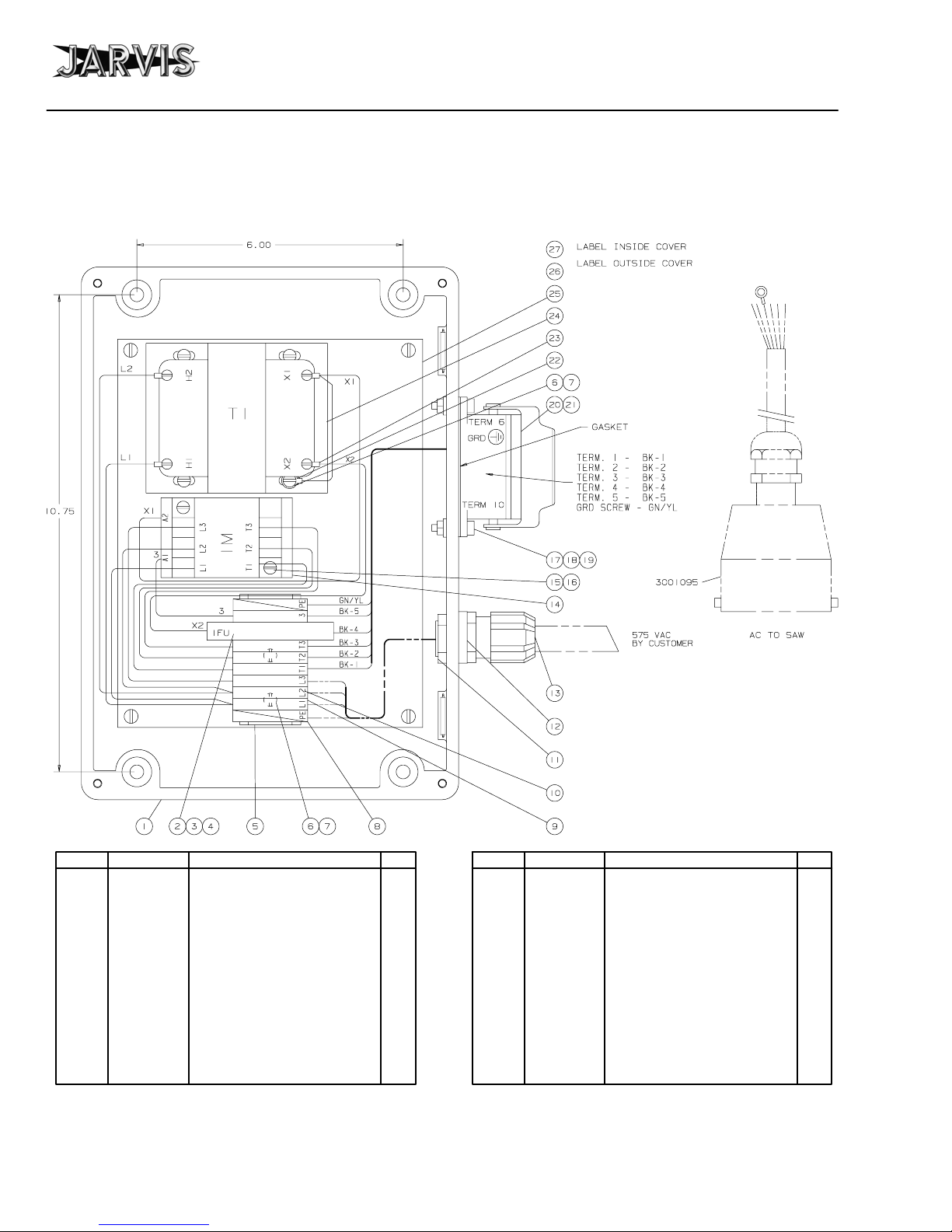
parts diagram and list
page 6 of 12
Figure B
575V Control Box
ITEM PART NO. PART NAME QTY
1 1016445 Electrical Enclosure 1
2 1063455 Fuse Terminal Block 1
3 1063456 Terminal Marker 1
4 1063473 Fuse 1
5 1063393 Terminal Rail 1
6 1055010 Pan Head Screw 6
7 1004022 Internal Lock Washer 6
8 1063496 Yellow/Green Terminal Block 2
9 1063494 Grey Terminal Block 7
10 1063363 Terminal Marker 9
11 1007278 Locking Nut 1
12 1004211 Sealing Washer 1
13 1011268 Cord Connector 1
14 1063552 Contactor 1
JARVIS
6205012:.
®
ITEM PART NO. PART NAME QTY
15 1055499 Pan Head Screw 2
16 1004199 Lock Washer 2
17 1055484 Pan Head Screw 4
18 1004006 Internal Lock Washer 4
19 1007192 Hex Nut 4
20 1063908 Connector Housing 1
21 1063905 Connector Female Insert 1
22 1063079 Wire Terminal Ring 1
23 1063089 Wire Terminal Ring 5
24 1063500 Transformer 1
25 1032320 Mounting Plate 1
26 1017085 Danger Label 1
27 1017231 Wiring Diagram Label 1
3063108 Complete Control Box
PRODUCTS CORPORATION
33 ANDERSON ROAD, MIDDLETOWN, CONNECTICUT 06457--4926
UNITED STATES OF AMERICA E--MAIL.
TEL. 860--347--7271 FAX. 860--347--6978 WWW. jarvisproducts.com
jarvis.products.corp@snet.net
specifications, installation
and operation instructions
page 7 of 12
Models EBS--1
SPECIFICATIONS
Models EBS--1
Motor Power 1.9 hp 1400 W
Operating Voltages
42, 115, 230, 400, 415 V, 3 phase, 50 Hz
220, 240, 380, 480 575 V, 3 phase, 60 Hz
Blade Lengths EBS--1 9.5 in 241 mm
10.5 in 267 mm
11.5 in 292 mm
13.0 in 330 mm
Blade Lengths EBS--1--H 15.8 in 400 mm
Blade Lengths EBS--1--HS 21.9 in 556 mm
Control Handle Single / Electric
Cut Speed at 60 Hz 750 ft/min 229 m/min
at 50 Hz 625 ft/min 191 m/min
Cutting Cycle Time 4 sec
Overall Length (w/o blade) 24 in 610 mm
OverallLength(9.5inblade) 28in 711mm
Weight 53 lbs 24 kg
2.3 Disconnect power cord (item 54 or 71) from
switch (item 50 or 73).
2.4 Remove two (2) locking nuts (item 57), cord
connector (item 55 or 70) and plug (item 60 or
76).
2.5 Swap positions of cord connector and plug. Re-tighten nuts.
2.6 Reconnect power cord (item 54 or 71) to switch.
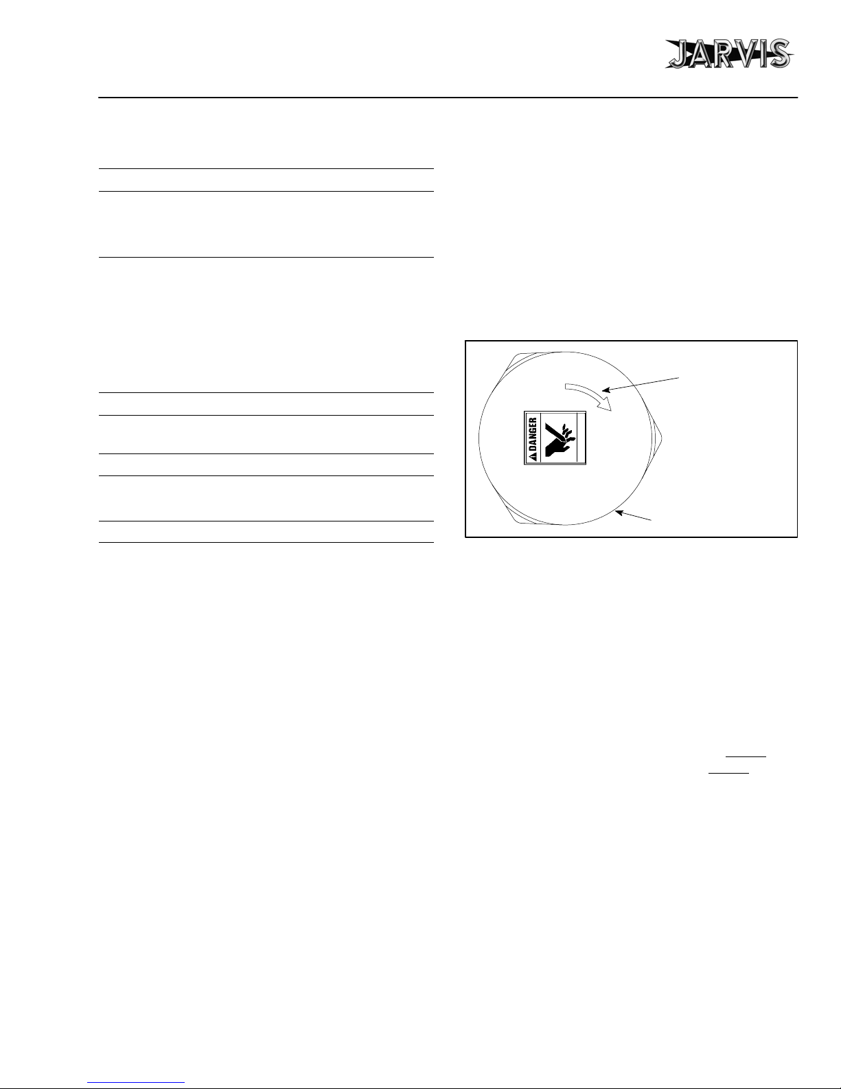
2.7 Check motor rotation. Motor rotation must follow direction of arrow shown in Figure 1.
Crank (item 33) will unscrew if motor direction is wrong.
Figure 1
Motor rotation must
follow direction of
arrow.
Keep hands clear.
Motor Cover
INSTALLATION INSTRUCTIONS
Refer to Figure A on page 4 for referenced items.
IMPORTANT: ALWAYS DISCONNECT THE ELECTRIC POWER SUPPLY IN ACCORDANCE WITH
OSHA’S LOCKOUT/TAGOUT PROCEDURES
(29CFR 1910.147) BEFORE PERFORMING ANY
MAINTENANCE OR REPAIRS.
ALL WIRING MUST BE DONE IN ACCORDANCE
WITH NATIONAL, STATE AND LOCAL ELECTRICAL CODES.
1 Install the Model EBS--1 saw above the work station
from a balancer. Jarvis part number 4042034 is
available.
1.1 The saw should have sufficient travel to allow
the operator to reach the entire work area.
2 Position power cord for either top exit or rear exit as
desired.
2.1 Unplug the tool.
2.2 Remove four (4) screws (items 53 or 69), electrical box cover (item 56 or 68) and g asket (item 58
or 67).
2.8 Reinstall gasket (item 58 or 67), cover (item 56
or 68) and four (4) screws (items 53 or 69).
3 Connect the tool to the appropriately fused electric
outlet.
OPERATION INSTRUCTIONS
1 Prior to use or daily perform the following tests:
1.1 Make sure that the saw moves freely on the balancer.
1.2 Make sure the control trigger is working correctly. Depress the trigger and the tool should
Release the trigger and the tool should
the tool malfunctions, remove it from service
and report the problem to your supervisor immediately.
Always use two hands when starting and
stopping the tool.
2 Make the cut:
2.1 Insert the saw blade into the cut made in a previous operation.
2.1.1 The front end of the saw should be tipped up
at approximately a 30 degree angle.
start.
stop. If
JARVIS
6205012:.
®
PRODUCTS CORPORATION
33 ANDERSON ROAD, MIDDLETOWN, CONNECTICUT 06457--4926
UNITED STATES OF AMERICA E--MAIL.
TEL. 860--347--7271 FAX. 860--347--6978 WWW. jarvisproducts.com
jarvis.products.corp@snet.net

Models EBS--1
operation and
maintenance instructions
page 8 of 12
2.2 Depress the trigger to start the saw.
Always use two hands when starting the tool
and making the cut.
2.3 Guide the saw down through the brisket applying a steady, even pressure to both handles.
2.3.1 The blade end of the saw should be pointing
upwards during the first part of the cut.
2.3.2 As the brisket starts to open, rotate the saw
to a horizontal position to finish the cut.
2.4 Release the trigger to stop the saw.
Continue holding the tool with two hands until the saw blade comes to a complete stop.
2.5 Remove the saw from the carcass.
2.6 Sanitize the saw blade.
MAINTENANCE INSTRUCTIONS
IMPORTANT: ALWAYS DISCONNECT THE
ELECTRIC POWER SUPPLY IN ACCORDANCE
WITH OSHA’S LOCKOUT/TAGOUT PROCEDURES (29CFR 1910.147) BEFORE INSTALLING
OR REMOVING A BLADE. ALWAYS DISCONNECT THE ELECTRIC POWER SUPPLY IN ACCORDANCE WITH OSHA’S LOCKOUT/TAGOUT
PROCEDURES (29CFR 1910.147) BEFORE PERFORMING ANY MAINTENANCE OR REPAIRS.
Refer to Figure A on page 4 for referenced items
1 PRIOR TO USE OR DAILY:
1.1 Make sure the control trigger is working correctly. Depress the trigger and the tool should
Release the trigger and the tool should
the tool malfunctions, repair or remove it from
service immediately.
The electric power supply must be connected
to perform the above operation only.
Always use two hands when starting and
stopping the tool.
1.2 Apply Jarvis 1315 White Grease to grease fitting (item 1). Apply grease to fitting by putting
a grease gun through the grease holes located on
the bottom cover (item 41). Refer to Figure 2.
Note: Correct application of grease into grease fitting
(item 1) depends on location of blade drive piston (item
9). If blade drive piston is fully extended, apply grease
to hole number 1. If blade drive piston is fully retracted,
apply grease to hole number 2.
start.
stop. If
1.3 Check all electrical plugs and cords (over their
entire lengths) for cuts and abrasions. Replace
if necessary.
2 MONTHLY:
2.1 Apply Jarvis 1315 White Grease to grease fitting (item 40). Apply grease to fitting by putting
a grease gun through the grease holes located on
the bottom cover (item 41). Refer to Figure 2.
Note: Correct application of grease onto grease fitting
(item 40) depends on location of blade drive piston (item
9). If blade drive piston is fully extended, apply grease
to hole number 3. If blade drive piston is fully retracted,
apply grease to slot number 4.
Grease Holes
No. 1
No. 2
No. 3
2.2 Inspect for wear on blade side guides (item 10).
Adjust for wear by removing outer set screws
(item 5). Turn inner set screws (item 5) to adjust
guide. Replace and tighten outer set screws to
secure adjustment. Replace side guides if necessary.
3 BLADE REMOVAL:
3.1 Remove hex head screws (item 6).
3.2 Remove blade (item 8, 80 or 81) from blade
drive piston (item 9).
3.3 Slide blade (item 8, 80 or 81) through saw blade
guard (item 7) and blade top guide (item 11).
4 BLADE INSTALLATION:
4.1 Reverse steps and procedures outlined in section
3.
Figure 2
No. 4
JARVIS
6205012:.
®
PRODUCTS CORPORATION
33 ANDERSON ROAD, MIDDLETOWN, CONNECTICUT 06457--4926
UNITED STATES OF AMERICA E--MAIL.
TEL. 860--347--7271 FAX. 860 --347--6978 WWW. jarvisproducts.com
jarvis.products.corp@snet.net

maintenance instructions
page 9 of 12
Models EBS--1
5 CRANK DISASSEMBLY:
5.1 Remove blade (item 8, 80 or 81). Refer to steps
and procedures outlined in section 3.
5.2 Rest saw on its side.
5.3 Remove hex head screws (item 42) securing
bottom cover (item 41) to main housing (item
28).
5.4 Remove saw blade guard (item 7) and bottom
cover (item 41).
5.5 Wedge hardwood block between crank (item
33) and main housing (item 28) to prevent crank
from rotating.
5.6 Unscrew and remove bearing cover (item 39).
5.7 If necessary, press grease fitting (item 40) out of
bearing cover (item 39).
5.8 Remove hex head screw (item 38) and washer
(item 37).
5.9 Remove grease fitting (item 1) and washer (item
2) from connecting link (item 35).
5.10 Remove connecting link (item 35).
5.11 Remove blade drive piston (item 9).
5.12 Press bushing (item 3) out of connecting link
(item 35).
5.13 Press bearing (item 36) out of connecting link
(item 35).
5.14 Remove socket head screws (item 4)
5.15 Remove blade side guides (item 10).
5.16 With crank (item 33) wedged, unscrew hex jam
nut (item 34).
Note: Hex jam nut (item 34) is secured with a thread
locking compound. Heat maybe required for removal.
5.17 Remove hardwood wedge.
5.18 Remove cheese head screws (item 23).
5.19 Remove motor cover (item 24).
5.20 Insert a 12 mm allen wrench onto rotor shaft
(item 26).
5.21 Unscrew and remove crank (item 33).
Note: Crank (item 33) is secured with a thread locking
compound. Heat maybe required for removal.
6 CRANK ASSEMBLY:
6.1 Reverse steps and procedures outlined in section
5. See special notes below:
6.1.1 After completing assembly, make sure connecting link (item 35) and blade drive piston
(item 9) move freely without any obstructions.
6.1.2 If removed or replaced, bushing (item 3)
and bearing (item 36) must be carefully
pressed into connecting link (item 35).
6.1.3 If removed or replaced, grease fitting (item
40) must be carefully pressed into bearing
cover (item 39).
6.1.4 Apply either Loctite 271 or Loctite 262
thread locking compound to crank (item 33)
and hex jam nut (item 34).
6.1.5 If blade side guides (item 10) have been replaced, set screws (item 5) must be readjusted. Refer to section 2.2 on page 8.
7 MOTOR DISASSEMBLY:
7.1 Move hanger (item 21) forward toward auxiliary handle (item 17).
7.2 Remove electric box cover (item 56 or 68) and
gasket (item 58 or 67).
7.3 Loosen screws (item 51 or 69) on switch (item
50 or 73) to disconnect power cord (item 54 or
71) and motor lead wires.
7.4 Remove cheese head screws (item 23) from motor cover (item 24).
7.5 Remove motor cover (item 24). Use three extractor screws (m8 x 1.25 x 16 mm long,
1055905) to jack cover off main housing.
7.6 Insert a 12 mm allen wrench into rotor shaft
(item 26) to prevent shaft from rotating.
7.7 Unscrew hex jam nut (item 34).
Note: Hex jam nut (item 34) is secured with a thread
locking compound. Heat maybe required for removal.
7.8 Unscrew and remove crank (item 33).
Note: Crank (item 33) is secured with a thread locking
compound. Heat maybe required for removal.
7.9 Remove rotor (item 26).
7.10 Remove bearing (item 25).
7.11 Remove beveled retaining ring (item 32).
7.12 Remove socket set screws (item 29).
JARVIS
6205012:.
®
PRODUCTS CORPORATION
33 ANDERSON ROAD, MIDDLETOWN, CONNECTICUT 06457--4926
UNITED STATES OF AMERICA E--MAIL.
TEL. 860--347--7271 FAX. 860 --347--6978 WWW. jarvisproducts.com
jarvis.products.corp@snet.net

Models EBS--1
maintenance instructions
page 10 of 12
7.13 Remove stator (item 27).
7.14 Press bearing (item 31) out of main housing
(item 28).
7.15 Inspect all parts for wear and replace if necessary.
8 MOTOR ASSEMBLY:
8.1 Reverse steps and procedures outlined in section
7. See special notes below:
8.1.1 Apply either Loctite 271 or Loctite 262
thread locking compound to crank (item 33)
and hex jam nut (item 34).
8.1.2 Check direction of motor. Refer to Installa-
tion Instructions, step 2.7 on page 7.
8.1.3 Make sure beveled retaining ring (item 32)
is correctly installed. Refer to Figure 3.
Figure 3
Rotor Shaft
Bearing
Correct position
of beveled
retaining ring.
9 REAR HANDLE DISASSEMBLY:
9.1 Remove oval head screws (item 45).
9.2 Remove rear handle bracket (item 62).
9.3 Remove screws (items 53 or 69).
9.4 Remove cover (item 56 or 68) and gasket (item
58 or 67).
9.5 Loosen screws (item 51 or 69) on switch (item
50 or 73) to disconnect power cord (item 54 or
71) and motor lead wires.
9.6 Remove four (4) cheese head screws (item 59).
9.7 Pull away rear handle (item 61 or 75) enough to
remove ground screw (item 59) fastening
ground lug to main housing (item 28).
9.8 Remove cheese head screws (item 51 or 66) and
switch holding clamp (item 52) and lift switch
(item 50 or 73) from rear handle (item 61 or 75).
9.9 Remove trigger bushing (item 48) and plunger
(item 49 or 74).
9.10 Inspect all parts for wear and replace if necessary.
9.11 Remove gasket (item 30).
10 REAR HANDLE ASSEMBLY:
10.1 Reverse steps and procedures outlined in section
9. See special note below:
10.1.1 Make sure to install gasket (item 30) before
connecting power cord wires (item 54 or 71)
to switch (item 50 or 73) and installing cover (item 56 or 68).
10.2 Check direction of motor. Refer to Installation
Instructions, step 2.7 on page 7.
JARVIS
6205012:.
®
PRODUCTS CORPORATION
33 ANDERSON ROAD, MIDDLETOWN, CONNECTICUT 06457--4926
UNITED STATES OF AMERICA E--MAIL.
TEL. 860--347--7271 FAX. 860 --347--6978 WWW. jarvisproducts.com
jarvis.products.corp@snet.net

notes
page 11 of 12
Models EBS--1
JARVIS
6205012:.
®
PRODUCTS CORPORATION
33 ANDERSON ROAD, MIDDLETOWN, CONNECTICUT 06457--4926
UNITED STATES OF AMERICA E--MAIL.
TEL. 860--347--7271 FAX. 860 --347--6978 WWW. jarvisproducts.com
jarvis.products.corp@snet.net

Models EBS--1
page 12 of 12
PRODUCTS CORPORATION
JARVIS
6205012:.
JARVIS
6205012:.
®
®
PRODUCTS CORPORATION
33 ANDERSON ROAD, MIDDLETOWN, CONNECTICUT 06457--4926
UNITED STATES OF AMERICA E--MAIL.
TEL. 860--347--7271 FAX. 860 --347--6978 WWW. jarvisproducts.com
PRODUCTS CORPORATION
33 ANDERSON ROAD, MIDDLETOWN, CONNECTICUT 06457--4926
UNITED STATES OF AMERICA E--MAIL
TEL. 860--347 --7271 • FAX. 860--347--6978 • WWW.jarvisproducts.com
jarvis.products.corp@snet.net
jarvis.products.corp@snet.net
 Loading...