

Page 1
490, rue de l'Argon
Quebec (Québec) G2N 2C9
Phone: 418-849-8095 Fax : 418-849-0077
www.jaroby.com
OWNER’S MANUAL
ULTIMATE ULTIMATE-B
HIGH EFFICIENCY WOOD STOVE
Revised December 04, 2013
ULTIMATE and ULTIMATE-B
Certified and tested
according to UL-1482-00
and ULC-S627-00 norms.
Page 2

2
TABLE OF CONTENTS
WARNING ...............................................................................................................................................3
NOTICE ....................................................................................................................................................5
Creosote ................................................................................................................................................5
SPECIFICATIONS - ULTIMATE and ULTIMATE-B .......................................................................6
INSTALLATION .....................................................................................................................................7
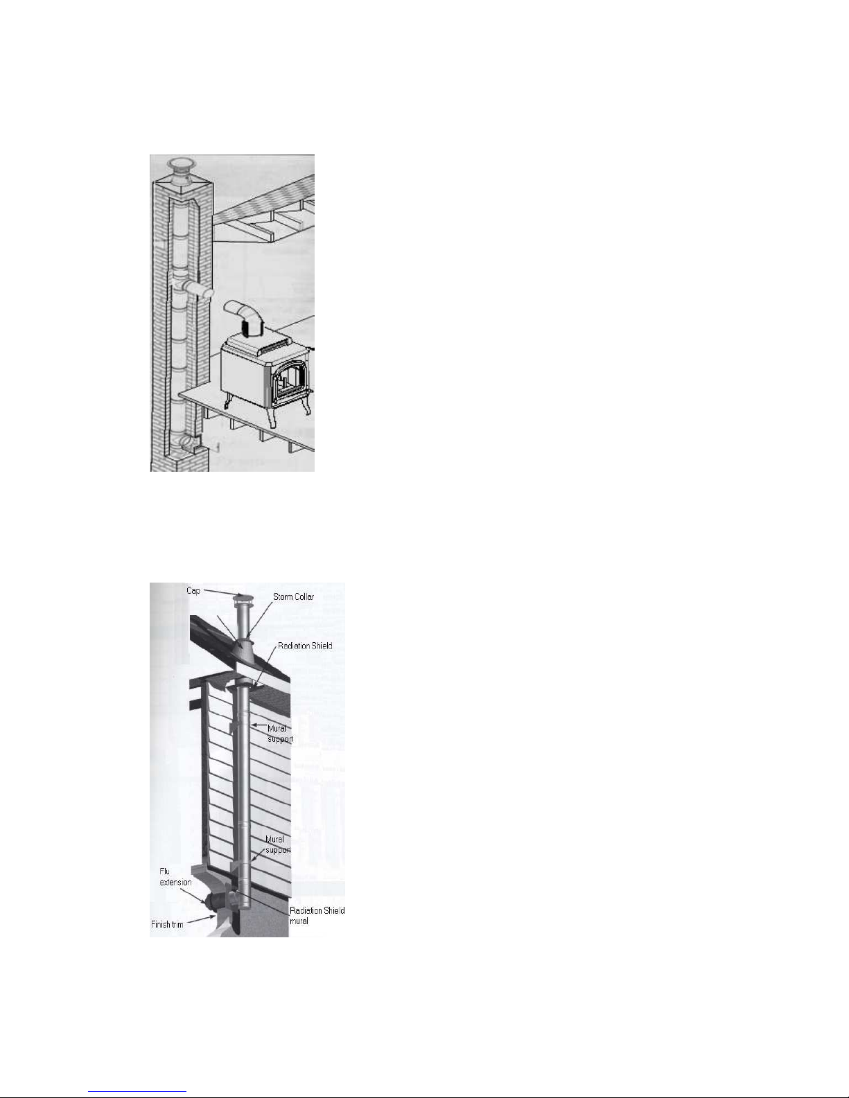
Vertical installation inside a masonry chimney ....................................................................................8
Exterior vertical installation .................................................................................................................8
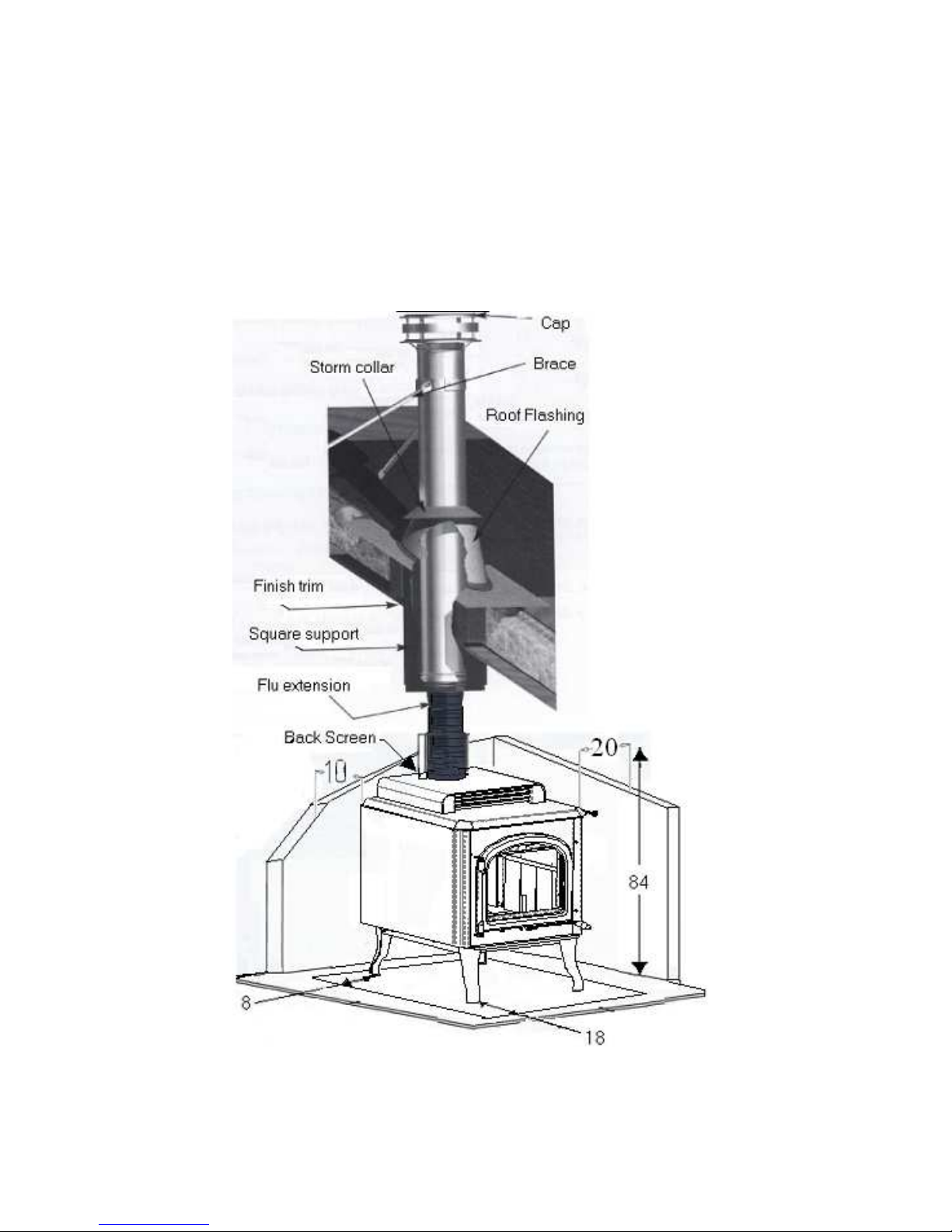
Vertical installation on a cathedral roof ...............................................................................................9
Cross installation ................................................................................................................................ 10
Vertical installation ............................................................................................................................. 10
CLEARANCES ...................................................................................................................................... 11
FLOOR PROTECTOR ......................................................................................................................... 12
DOOR ADJUSTMENT ......................................................................................................................... 13
LIGHTING ............................................................................................................................................. 13
FANS AND THERMODISC ................................................................................................................. 14
PREVENTIVE MEASURES AND MAINTENANCE ....................................................................... 15
Replacement part l ist ............................................................................................................................ 16
INSTALLATION OF THE FIREBRICKS ......................................................................................... 17
Figure 1 . 0 .......................................................................................................................................... 18
WARRANTY ......................................................................................................................................... 20
READ CAREFULLY THIS MANUAL AND KEEP IT FOR FURTHER
REFERENCES.
INSTALLATION OF THIS APPLIANCE MUST BE DONE BY A QUALIFIED AND
CERTIFIED TECHNICIAN AND IN CONFORMITY WITH THE OWNER'S MANUAL
GUIDE PROVIDED WITH THIS APPLIANCE. THE INSTALLATION MUST BE IN
ACCORDANCE WITH LOCAL AND NATIONAL APPLICABLE REGULATIONS AND
THE APPLICABLE BUILDING CODE.
Warning! Never modify this appliance!
Page 3

3
WARNING
Before installing, please take a few minutes to read this handbook. Keep it in a sure place
and easily reachable for future references. If this appliance is not properly installed, it
could cause fire damages to the property, injuries and death. To reduce fire hazards,
follow instructions contained in this handbook.
Contact an official inspector (ex: a fireman) or your insurance company for installation
permit. Always respect the provincial and municipal building codes of your region.
Do not connect this appliance to a chimney that already serves for another wood stove.
The existing chimney should be inspected before any installation. In doubt, consult a
specialist.
Never use a non-isolated exterior conduct or a single pipe as an exterior exit.
Minimum clearances found in this manual must be observed.
Install all firebricks before lighting the stove (if it is not already done).
Never use a non-isolated exterior duct or a pipe to evacuate chimney smoke.
Do not install in a mobile house.
Keep all combustible material (clothing, furniture, wood, matches, plastic, etc) at a
distance of at least 91.5 cm (3 feet) from the appliance.
Do not use chemicals or fluids to light the fire. Waste and other flammable materials such
as gasoline, naphtha or engine oil should not be burnt in your stove.
This appliance is approved to burn wood. Do not use any other combustible.
Wood should not be stocked within the recommended minimums clearances or in the
necessary space for the loading and the ashes evacuation.
Do not burn wet or freshly cut wood. Do not use construction debris such as pieces of
2x4 or plywood.
If the appliance starts to glow red, over firing is happening. Do not add fuel. Immediately
close the doors and the air intake of the appliance until everything becomes normal again.
Do not charge the appliance beyond the firebricks height.
Page 4
4
Ashes must be evacuated frequently, remove it with a small steel shovel.
Very hot while in operation. Keep the children away. Can cause burns by contact.
Considering the need of air for the combustion, a window or a door must be half opened
sometimes (fresh air drainage) to balance the pressure in the house, especially if:
- A fan already evacuates air towards outside (kitchen, bathroom.)
- You want to avoid smoke spillage when lighting the appliance and when reloading
the wood.
It is recommended to have a smoke detector near the appliance.
You should contact your municipal or provincial fire department to have knowledge
of the procedure to be followed in case of a chimney fire. Think of an emergency
plan.
In case of a chimney fire:
- Hermetically close the doors and the air intakes.
- Water the combustible material adjacent to the chimney.
- Ring the alarm, evacuate the house if necessary and call the firemen.
- Never touch the pipes until the fire is not completely extinct.
- Do not use the chimney until it has been inspected or repaired.
Keep all the doors closed while the appliance is in function. Frequently verify the
ceramics cords; they must always be in good condition.
The chimney pipe should not pass close to water, gas or oil pipes, or close to electric wire
or other types of conduits, of combustible materials in the roofs, the attics, the walls or
the floors. If you have to make it pass through a wall or a part of combustible
construction, do not forget that the installation must be in accordance with the
CAN/CSA-B365. Use at least 12 feet of a 6 inches diameter vertical chimney.
NOTE:
FOLLOW THESE
INSTRUCTIONS IN ORDER
TO AVOID FIRE HAZARDS,
WOUNDS AND PROPERTY
DAMAGES.
Page 5

5
NOTICE
The Ultimate was conceived to safely function the doors closed and only when burning
firewood. Any change, modification or unauthorized installation will automatically
cancel the certification of the appliance, its guarantee, its homologation and the appliance
might become dangerous.
During the first hours of operation of your appliance, you must gradually heat it without
exceeding 300°F (145°C), in order to let the paint cook slowly and to facilitate its
adhesion with metal. It is normal that a light smoke is released from the paint during the
first hours of use.
Even if this nuisance is temporary, open the windows and the doors in order to ensure
good ventilation. This special paint is conceived to tolerate temperatures until 1200°F
(650°C).
C
REOSOTE
The wood burning slowly produces tar and other organic steams, which forms a whole
called “creosote”. The steam condenses in the cool chimney when the wood is burning
slowly. In this way, creosote residues are formed on the walls. Creosote can take several
forms: tarry liquid, soot dust or deposits in crystal form. When in fire, the creosote
releases a very strong heat and can be the cause of a chimney fire.
- Do not knock on the glasses or violently close the doors.
- Do not use the appliance when a glass is broken or damaged.
- Do not build the fire close to the glass.
- Keep the door closed when using the appliance.
- Do not connect the Ultimate with a chimney or a flue serving another heating
appliance
Page 6

6
SPECIFICATIONS - ULTIMATE AND ULTIMATE-B
Combustible
Wood
Recommended surface
500 à 3000 ft² (46,5 à 278,70 m²)
Evacuation pipe diameter
6 in (15,24 cm)
Chimney minimal height
12 ft (3,66m)
Dimensions
Exterior height
35.8 in. (90,9 cm)
Exterior width
27,5 in. (70,0 cm)
Exterior depth
37 in. (94 cm)
Door openning
16 X 10,5 in. (41,0 X 27,0 cm)
Interior height
13,5 in. ( 34,3 cm)
Interior width
20,5 in. (52,1 cm)
Interior depth
25,25 in. (64,1 cm)
Maximal length of log
25 in. (64 cm)
Combustion duration
6 to 12 hours
Weight
460 pounds (208 kg)
Clearances
Back
10 in. (25,4 cm)
Lateral
20 in.(50,8 cm)
Floor to Ceiling
84 in. (213,4 cm)
Page 7

7
INSTALLATION
A good installation is extremely important for a safe and efficient use of your J. A. Roby
Inc. appliance. If you doubt on the way to install the appliance correctly, seek for
professional installation service. We suggest you to call masters fitters.
1. Withdraw firebricks placed inside the appliance in order to reduce the weight and
to facilitate the installation.
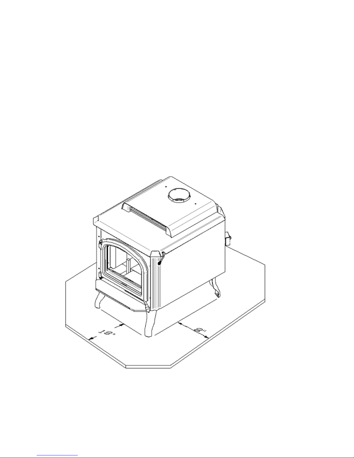
2. You must install a fireproof protector under the appliance, which must exceed of
18 inches to the front and of 8 inches on each side.
3. The free space shall not be reduced except under the approval of the authorities
responsible for the application of the building code.
4. Install the chimney and an insulated wall thimble for an installation passing
through a wall according to the instructions from the chimney manufacturer.
5. The chimney must exceed any part of the building or other obstruction within a 10’
(3.04m) distance by a height of 2’(0.6.m) rising above the roof to a minimum of 3’
(0.0m) from the uppermost point of contact.
6. Install the firebricks in accordance with the recommended instructions for your
model.
7. The appliance should not be connected to an hot air conduct
8. Installation of an interior chimney is always preferable to an exterior chimney
being heated up by the ambient air in the house and the gases which circulate will
cool more slowly.
Page 8
8
V
ERTICAL INSTALLATION INSIDE A MASONRY CHIMNEY
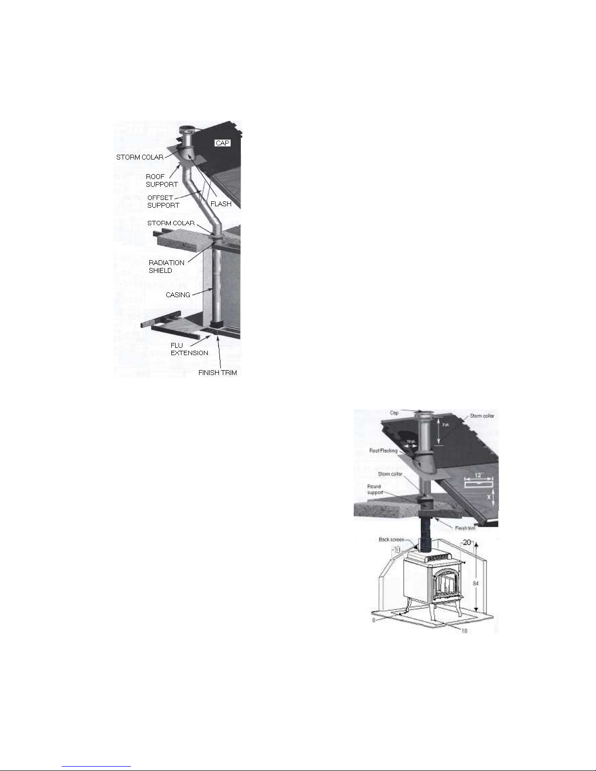
The Ultimate and Ultimate-B models must be installed in
accordance with the applicable local laws or the CAN/CSA B365 ULC S635, ULC S640, UL 1777 norms. For the
chimney, follow the chimney manufacturer's instructions.
E
XTERIOR VERTICAL INSTALLATION
The Ultimate and Ultimate-B models must be
installed in accordance with the applicable local
laws or the CAN/CSA - B365 ULC S635, ULC
S640, UL 1777 norms. For the chimney, follow
the chimney manufacturer's instructions.
Page 9
9
V
ERTICAL INSTALLATION ON A CATHEDRAL ROOF
The Ultimate and Ultimate-B models must be installed in accordance with the applicable
local laws or the CAN/CSA - B365 ULC S635, ULC S640, UL 1777 norms. For the
chimney, follow the chimney manufacturer's instructions.
Page 10
10
C
ROSS INSTALLATION
The Ultimate and Ultimate-B models must be
installed in accordance with the applicable local
laws or the CAN/CSA - B365 ULC S635, ULC
S640, UL 1777 norms. For the chimney, follow
the chimney manufacturer's instructions.
V
ERTICAL INSTALLATION
The Ultimate and Ultimate-B models must be
installed in accordance with the applicable
local laws or the CAN/CSA - B365 ULC
S635, ULC S640, UL 1777 norms. For the
chimney, follow the chimney manufacturer's
instructions.
Page 11
11
CLEARANCES
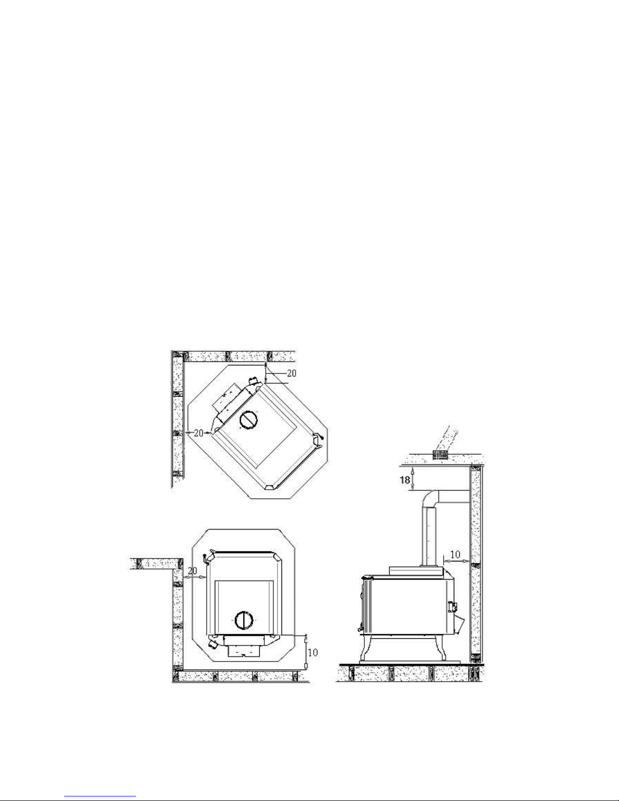
Due to its reduced clearances, this appliance occupies a minimum of space in the room
where it is installed. No matter where you install it, the Ultimate and Ultimate-B models
will complete perfectly your decoration by their originality and their heat. With the
addition of a heat shield, they requires only 10 inches of clearance to the back and 20
inches of the sidewalls, when the installation is made with a simple pipe, the clearances
must be 18 inches to the front and the back. In the case of a simple pipe without an heat
shield, the clearances are of 18 inches of the smoke pipe.
Page 12
12
FLOOR PROTECTOR
Your wood stove should be placed on a non-combustible plate under the appliance, which
must exceed 18 inches to the front, 8 inches on each side and 8 inches to the back.
*** Only use non-combustible materials.
Ex : (ceramic, marble, granite)
Page 13

13
DOOR ADJUSTMENT
In order for your stove to operate properly, the door should be adjusted using the small
wrench tool to provide an air tight fit:
To adjust: Turn clockwise until the door is air tight.
LIGHTING
Now that you have completed the installation of the appliance according to the
recommendations, you are ready for the lighting!
1. Before lighting, be sure that the chimney is warm enough by twisting together a
few sheets of newspaper in a torch. Light up the paper torch and hold it as close as
possible to the pipe inside the chamber to warm up the chimney.
2. Place papers and kindling in the appliance.
3. When the fire is well lit, gradually add bigger wood logs until an ember bed is
formed.
4. You can then control combustion by closing or opening the air intakes (a rod
pulled down indicates a closed air intake). The wood will burn more quickly if the
air intakes are opened to the maximum and more slowly if they are only slightly
open.
Do not charge the appliance beyond the bricks
.
Page 14
14
FANS AND THERMODISC
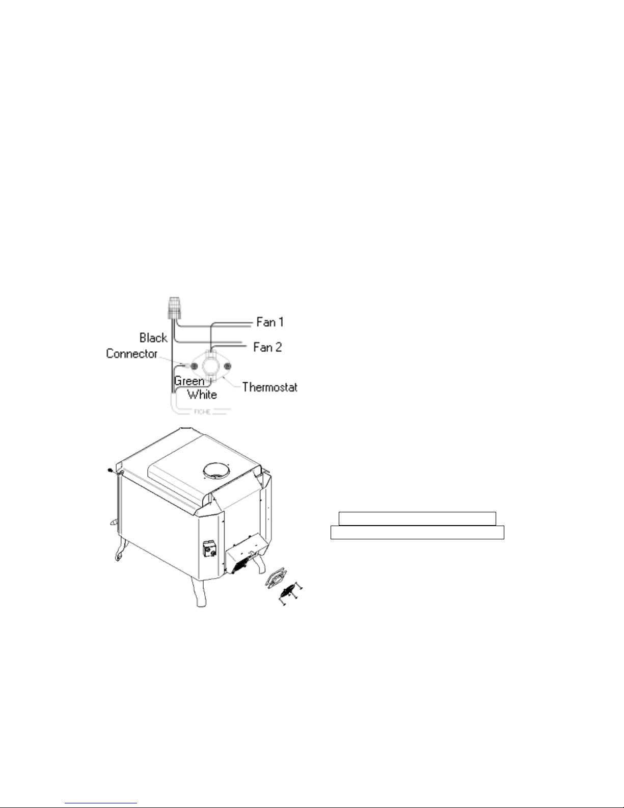
The 115 volts fans must be screwed with the grids beneath the air corridor. The thermo
disc box must be screwed on the back of the corridor. Connect the thermo disc into the
electrical outlet. When the appliance is in function, the heat reaching a temperature of
120oF activates the thermo disc. At this moment, the thermo disc activates the fans for a
better distribution of heat in your home. As soon as the heat goes under 120oF, the thermo
disc automatically stops the fans.
Be sure that the electric cord of the fan doesn't touch any surface of the appliance in order
to avoid an electric shock or a fire hazard.
DO NOT PUT THE ELECTRIC
CORD UNDER THE APPLIANCE.
Page 15

15
PREVENTIVE MEASURES AND MAINTENANCE
1. We recommend opening the air intakes completely and to maintain an intense fire
from 10 to 20 minutes per day or use a chimney thermometer, as flue gases should
reach at least 350° F before closing the air intake.
2. Verify the accumulation of creosote every week that you use the appliance until
you know at which frequency it must be cleaned (minimum once per year).
3. Remove creosote deposit in order to prevent chimney fires.
4. The interior diameter of the chimney flue must be identical to the smoke exhaust.
A flue which is too small may cause draught problems, while a large flue favours
rapid cooling of the gas, and hence the build-up of creosote.
Note that it is the chimney and NOT the stove that creates the draught effect. Your
stove’s performance is directly dependent on an adequate draught from your
chimney.
5. Do not alter or modify the air intakes of the appliance in order to get a stronger
fire.
6. To clean the glasses, J.A. Roby Inc. recommends using products sold for this
purpose or an oven cleaner. Avoid cleaning with abrasives or when the glass is
hot.
7. Before lighting the first fire, clean the gold plated surfaces using a very soft rag
moistened with water. Do not use a paper towel to clean gildings. If they are not
erased before the first fire, fingerprints and other marks could stain these surfaces
permanently.
GLASS REPLACEMENT
:
Remove the screws that retain the glasses and if need be, the fragments of glasses. Check
if the seal cords are damaged.
If so, replace them by a ½ inch ceramics cord and replace the broken glasses with a
VITROCERAMIC glass of 5mm.
Cut the glass edge 3mm smaller on each side, so that the fiberglass cord can be slipped on
the edge of the glass at the time of its installation. Secure the glass with the screws.
Contact your retailer to obtain any information you might need for the replacement
of the glass.
DO NOT USE SUBSTITUTES.
Page 16

16
REPLACEMENT PART L IST
• BRICKS
• WOOL
• PLATES USED TO RETAIN WOOL
• PIPES
• GLASS
• BRICKS SUPPORTS
• DOOR HANDLE
• FANS
•
CORDS
*
T
O ORDER PARTS, PLEASE CONTACT YOUR AUTHORIZED RETAILER
.
Page 17

17
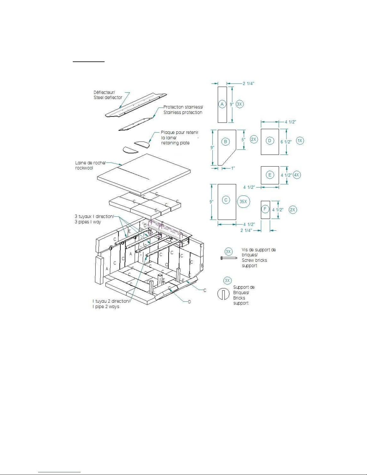
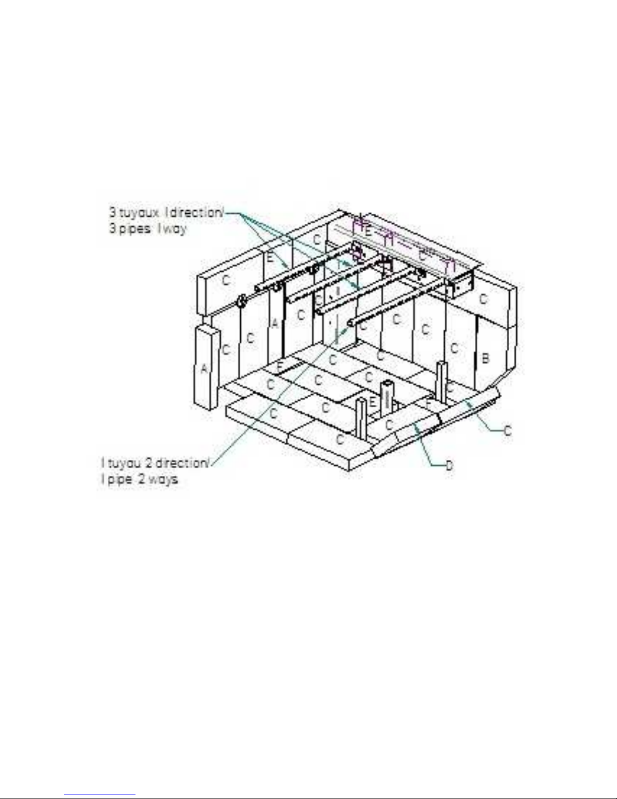
INSTALLATION OF THE FIREBRICKS
1. Before you begin, please take note that the purpose for the screws is to secure the
bricks inside the stove.
2. First, install the bricks C (10), F (2), E (1) at the bottom of the stove and C (1) &
D (1) on the inclined part near the door.
3. Second, install the bricks to the bottom of the back wall 4 (C),1 (A) pre-screw the
brick supports and screws add C(2) and E(1),when all bricks and supports are
installed you can then tighten the screws.
4. Third, install C (12) B (2) A (2) E (2) bricks on the side wall.
5. To install the last top bricks, the rock wool and the retaining plate, follow the last
step before lighting the stove.
- Add the 3 bricks on the pipes. Then add the rock wool and the 2 retaining plates on
the bricks. To finish the installation, put the last 3 bricks between the first and the
second pipe and put-it on the pipes.
BRICKS: Qties
A 2 ¼” X 9” : 3
B 5” X 9” with 1” angle: 2
C 4 ½” X 9” : 35
D 6 ½ X 4 ½” : 1
E 4 ½” 4 ½“ : 4
F 4 ½” X 2 ¼” : 2
G brick support: 3
H screws for support: 3
***Please take note that that step 1 to step 3 is already done at the factory***
Page 18
18
Figure 1 . 0
Page 19
19
Page 20
20
STOVES & FIREPLACES
WARRANTY
J. A. ROBY LIMITED LIFE WARRANTY – WOOD BURNING STOVES & FIREPLACES
J. A. ROBY’s warranty only applies to original buyer and is non-transferable. This warranty covers brand new
products only, which have not been altered, modified nor repaired since shipment from factory. The products covered
by this warranty must be manufactured after review date indicated at the bottom of page. Proof of purchase (dated bill
of sale), model name and serial number must be supplied when making any warranty claim to your J. A. ROBY dealer.
Registered your warranty is not required.
The appliance must be installed by an authorized service technician or contractor. Installation must be done in
accordance with the installation instructions included with the product and all local and national building and fire
codes. Any service call related to an improper installation is not covered by this warranty. This warranty applies to
normal residential use only. This limited warranty does not cover damages caused by misuse, improper installation,
lack of maintenance, accident during transportation, alterations, power failure, venting problems, downdrafts, abuse,
over firing or neglect. Operating the appliance on high for extended periods of time is neglect. Any defect or damage
caused by the use of unauthorized parts or others than original parts void this warranty.
This limited warranty does not cover any scratch, corrosion, warping or discoloration. The manufacturer may
require that defective products be returned and/or that digital pictures be provided to support the claim. Returned
products are to be shipped prepaid to the manufacturer for investigation. If a product is found to be defective, the
manufacturer will repair or replace such defect. The transportation fees to ship back the product to the purchaser will be
paid by the manufacturer2. The external labour fees related to warranty repair are not covered. The manufacturer may
at its discretion, decide to repair or replace any part or unit after inspection and investigation of the defect. The
manufacturer may at its discretion, fully discharge all obligations with respect to this warranty by refunding to the
original warranted purchaser the wholesale price of any warranted but defective part (s). The manufacturer shall not in
no event be liable for any special, indirect or consequential damages of any nature whatsoever which exceeds the
original purchase price of the product. All parts replaced under this limited life warranty are subject to a single claim.
Any damage to the appliance, combustion chamber, heat exchanger, enameled cast iron cooking plate or other
components due to water, weather damage, long periods of dampness, condensation, damaging chemical or cleaner will
not be the responsibility of J. A. ROBY. Failure of any components which is attributed to poor maintenance, is not
warrantable and will not be covered by this policy. J.A. ROBY neither assumes, nor authorizes any third party to
assume, on its behalf, any other liabilities with respect to the sale of this product.
The manufacture of your new appliance and the following materials are warranted against defects as mentioned
below:
WARRANTY DESCRIPTION 100%
50%
current retail
price
Ashtray, handles, doors and cast iron legs
Life
Combustion chamber 5 years
From 5
years to life
Secondary air tubes
5 years
Heat exchanger 2 years
From 2
years to life
Switches, thermodisc, wiring and electrical components, standard blowers
and rheostat
2 years
Tempered glass, optional blower and gasketing
1 year
Ce
ramic glass (thermal breakage only
1
) 1 year
Replacement parts (with proof of purchase)
90 days
Due to on-doing product improvements, all specifications and design are subject to change without prior notice.
Before shipping your unit or defective component to our plant, you must obtain from J. A. ROBY dealer an
authorization number. Any merchandise shipped to our plant without authorization will be refused
automatically and returned to sender.
1= Digital pictures required 2= Shipping cost are not covered outside CANADA
Review oct. 2014
 Loading...