

Page 1
OWNER’S MANUAL
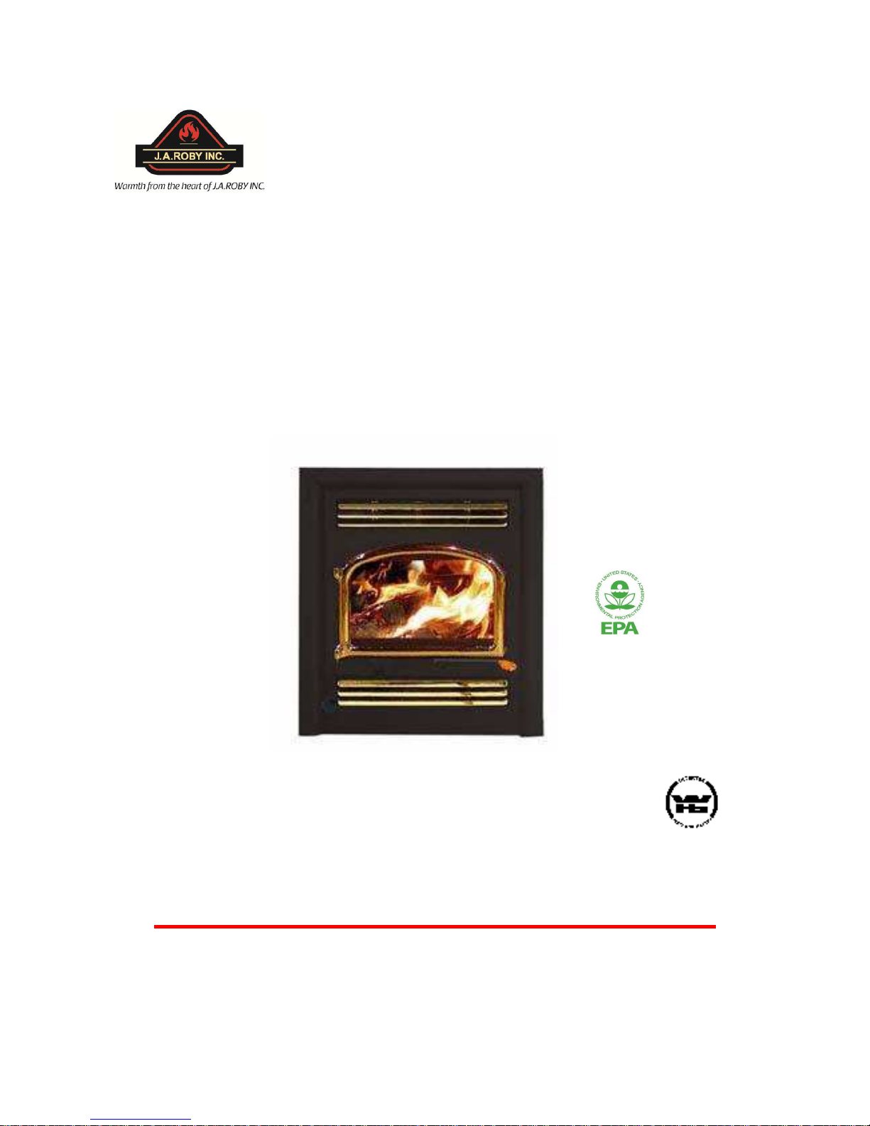
EVOLUTION
June 3rd, 2009 Reviewed
EVOLUTION & EVOLUTION 2113
490, rue de l'Argon, Quebec, Qc CANADA G2N 2C9
Phone: 418-849-8095 Fax : 418-849-0077
www.jaroby.com
CAN/ULC_S610-M87
Restricted fireguard utilization
Page 2

TABLE OF CONTENTS
SPECIFICATIONS – EVOLUTION .................................................................................. 1
WARNING ......................................................................................................................... 2
NOTICE .............................................................................................................................. 4
C
REOSOTE
........................................................................................................................ 4
LOCATION OF THE FIREPLACE ................................................................................... 5
INSTALLATION OF THE CHIMNEY ............................................................................. 6
C
HIMNEY FRAME DETAILS
............................................................................................... 6
INTERMEDIATE JOIST ENTRY
CF ....................................................................................... 7
A
TTIC THERMAL SCREEN INSTALLATION
.......................................................................... 7
I
NSTALLATION OF THE RADIANT FIREBREAK
.................................................................... 8
I
NSTALLATION OF ELBOWS
............................................................................................... 8
I
NSTALLATION OF THE EXTERIOR CHIMNEY
..................................................................... 9
CF
ROOF SUPPORT
............................................................................................................ 9
CF
INTERIOR SUPPORT / DEVIATION SUPPORT
................................................................. 10
I
NSTALLATION OF THE ROOF FLASHING
.......................................................................... 10
B
LOWHOLE SYSTEMS AUTHORIZED
................................................................................ 12
EXTERIOR AIR CANALIZATION ................................................................................ 14
INTERNAL BLOWER (FANS AND THERMODISC) .................................................. 15
BLOWHOLE BY NATURAL CONVECTION .............................................................. 16
CENTRAL BLOWER ...................................................................................................... 18
INSTALLATION OF THE 460 CFM FAN ..................................................................... 20
EXTRUSION .................................................................................................................... 22
INSTALLATION OF THE FIREBRICKS ...................................................................... 22
DOORS ADJUSTMENT .................................................................................................. 23
SHELF .............................................................................................................................. 23
LIGHTING ....................................................................................................................... 24
FIREGUARD .................................................................................................................... 24
PREVENTIVE MEASURES AND MAINTENANCE.................................................... 25
INTERCHANGEABLES PARTS LIST........................................................................... 26
WARRANTY ................................................................................................................... 28
Page 3
CAREFULLY READ THIS MANUAL AND KEEP IT FOR FURTHER
REFERENCES.
INSTALLATION OF THIS APPLIANCE MUST BE DONE BY A QUALIFIED AND
CERTIFIED TECHNICIAN AND IN CONFORMITY WITH THE OWNER'S
MANUAL GIVEN WITH THIS APPLIANCE. THE INSTALLATION MUST BE IN
AGREEMENT WITH LOCAL AND NATIONAL REGULATIONS APPLICABLE
FOR SOLID FUEL BURNING APPLIANCES AND CONNEX EQUIPMENT
(CAN/CSA-B365) AND THE APPLICABLE BUILDING CODE .
WARNING! NEVER MODIFY THIS APPLIANCE !
NEVER USE THE FIREGUARD (PAREV) WITH A 18000, 1" OF ISOLATED
CHIMNEY (ULC-S604).
Page 4

Page 1
SPECIFICATIONS – EVOLUTION
Combustible
Wood
Recommended surface
0 to 2000 Ft² (0 to 186m2)
Evacuation pipe diameter
6“ (15,24cm)
Chimney minimal height
15 ft (457,2cm)
Hot air top exit
6“ (15,24cm)
Dimensions:
Glass viewing area (W X H):
ATC 618 (2 doors)
15” X 12 ¾” ( 38X 32.4cm)
Evolution (1 door)
18 ¾” X 12 ¼” (47.6 X 31cm)
Evolution (2 doors)
20 3/8” X 12 ¼” (52 X 31cm)
Evolution 2113
21” X 13” (53 X 33cm)
Exterior width
32“ (81,28cm)
Exterior depth
25” (63,5cm)
Door opening
20 ¼” X 10 ¾” (51,44cm X 27,31cm)
Inside height
13” (33cm)
Inside width
19” (48,26cm)
Inside depth
17 5/8” (44.8cm)
Maximal length of log
18” (45,72cm)
Weight
402 pounds
Clearances
Back
0
Lateral
0
In corner
0
Roof
84 in (213,36cm)
Page 5

2
WARNING
Before installing, please take a few minutes to read this handbook. Keep it in a sure place
and easily reachable for future references. Not following these instructions could be a
cause of property damages, injuries or death. If this appliance is not properly installed, it
could cause fire damages to the property, injuries and death. To reduce fire hazards,
follow instructions contained in this handbook.
Contact an official inspector (ex: a fireman) or your insurance company for installation
permit. Always respect the provincial and municipal building codes of your region.
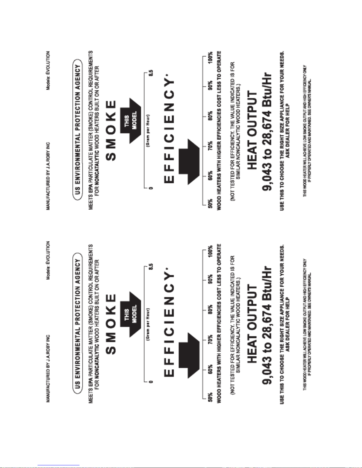
Your fireplace is a high efficiency appliance certified EPA. It will offer comfort and
pleasure if well installed, maintained and used.
Do not use in a mobile house.
This appliance must not be installed inside a prefabricated fireplace without being tested
first. This fireplace must have its own chimney. Do not connect it to a chimney pipe
already serving another appliance. It is recommended to regularly inspect the chimney.
Utilization of the fire-guard is authorized only with a 21000 chimney (ULC-S629). It is
strictly prohibited to use it with the doors open if the installation was made with a 18000
chimney of 1" isolation (ULC-S604). Do not place insulating material or pass electric
cords in the minimum clearances required for the air passage surrounding the chimney.
You can operate your fireplace with the doors completely open only if you have installed
a 2" chimney and have put the fireguard on the fireplace.
Do not block or modify the air circulation grids.
This appliance is certified to burn wood. Do not use any other combustible. Always use
dried wood. Do not burn green or wet wood. Do not use construction debris such as
pieces of 2x4, plywood... We recommend 16" logs. For a better efficiency, cross the logs
one on an other.
CAUTION :
Very hot while in function
Keep children far away from the appliance.
Never let the appliance without supervision when the door is open.
Never let the doors partly open when in function. Use completely close or
completely open with a fireguard.
Do not use chemical products or other liquid to light the fire.
Do not burn waste or inflammable fluids like gas, naphtha or motor oil.
Combustible materials should not be placed in front of the fireplace
A 2" (5,08cm) minimum clearance must always be maintained between the
chimney and any other combustible materials.
Page 6
3
Be sure that the ashes evacuation cap is closed before lighting.
If the evacuation conduct starts to blush, it's because it is too charged. The wood logs
shall never stand higher than the firedog in front of the fireplace.
Ashes must be evacuated frequently, put in a steel container provided with a tight cap and
be placed outside at once. You must never place other waste in this container.
Your fireplace can be use to warm up adjacent rooms or rooms on another floor. A mural
thermostat situated in the room to be heated controls the central blower which provides
hot air from the fireplace.
Be sure to have enough exterior air. Some domestic appliances use exterior air: the
kitchen fan, the extractor fan, heating appliances working by forced air. If you use an
exterior air device, you will not experience a lack of exterior air.
You should contact your municipal or provincial fire department to have knowledge
of the procedure to be followed in case of a chimney fire. Think of an emergency
plan.
Out of control fires can be caused by three main factors:
1. Utilization of inappropriate combustibles or the use of small wood which should
be use only for the lighting.
2. A door let partly open for too long.
3. Operation of your fireplace without the ashes cap.
To avoid out of control fires:
1. Do not burn treated or transformed wood, charcoal or colored paper.
2. Do not overload the appliance and do not let the door slightly open for a long
time after the lighting.
3. Be sure that the ashes cap is at its place before each use.
What to do in case of an out of control fire:
1. Close the air intakes and the doors.
2. Call firemen.
3. Examine the chimney, the attic and the roof to see if some components have
become abnormally hot. If necessary, drench with a fire extinguisher or a hose.
4. Do not use the fireplace before a complete inspection of your chimney and
fireplace.
NOTE :
FOLLOW THESE INSTRUCTIONS
IN ORDER TO AVOID FIRE
HAZARDS, WOUNDS AND
PROPERTY DAMAGES.
Page 7

4
NOTICE
Your fireplace Evolution was tested and approved including supports, firebreak and other
chimney components. Any change, modification or unauthorized installation will
automatically cancel the certification of the appliance, its guarantee, its homologation and
the appliance might become dangerous.
If the chimney is to be exterior, it is recommended to compartmentalize it in order to
protect it from the cold temperatures. This could improve the operation of the appliance.
Exterior partitions can be isolated by maintaining a 2 inches minimum clearance from the
chimney.
During the first hours of operation, you must heat it gradually. In order to allow an
appropriate cooking of the paint and in order to facilitate its adhesion with metal, do not
heat the appliance with a strong fire. It will also avoid thermal shock which could lift up
the paint or make it whiten. Make sure that the room is ventilated enough in order to
eliminate the odours and the smoke coming from the paint during the first hours of
utilization. It is normal that a light smoke is released from the paint during the first hours
of use.
Even if this nuisance is temporary, open the windows and the doors in order to ensure a
good ventilation. This special paint is conceived to tolerate temperatures until 1200°F
(650°C).
C
REOSOTE
The wood burning slowly produces tar and other organic steams, which forms a whole
called “creosote”. The steam condenses in the cool chimney when the wood is burning
slowly. In this way, creosote residues are formed on the walls. Creosote can take several
forms: tarry liquid, soot dust or deposits in crystal form. When in fire, the creosote
releases a very strong heat and can be the cause of a chimney fire. If there is 1/8 inches of
creosote or more in the chimney, you must remove it in order to avoid chimney fires.
- Do not knock on the glasses or violently close the doors.
- Do not use the appliance when a glass is broken or damaged.
- Do not build the fire too close of the glasses. Place the logs behind the two firedogs.
- Do not burn treated wood, charcoal, waste or plastics.
Page 8
5
LOCATION OF THE FIREPLACE
- Take knowledge of municipal and fire department requirements.
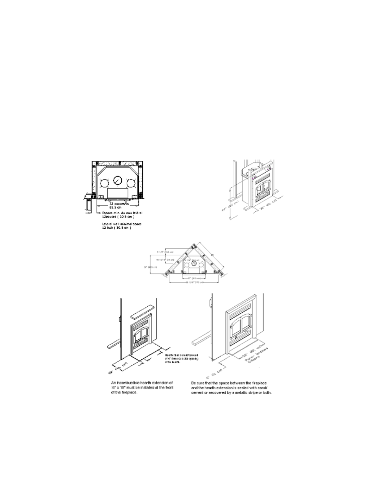
- Choose a place where you will not have to cut joist.
- The fireplace must be installed against a finished wall around the appliance
- The top of the fireplace must stay free.
- The roof height must be at minimum seven (7) feet from the floor.
- The minimum distance of installation between the opening of the fireplace and every
adjacent wall is of 12 inches, 48 inches at the front and the extension of the hearth is
of 18 inches at the front.
- Do not add isolating wool in the space surrounding the fireplace.
Page 9
6
INSTALLATION OF THE CHIMNEY
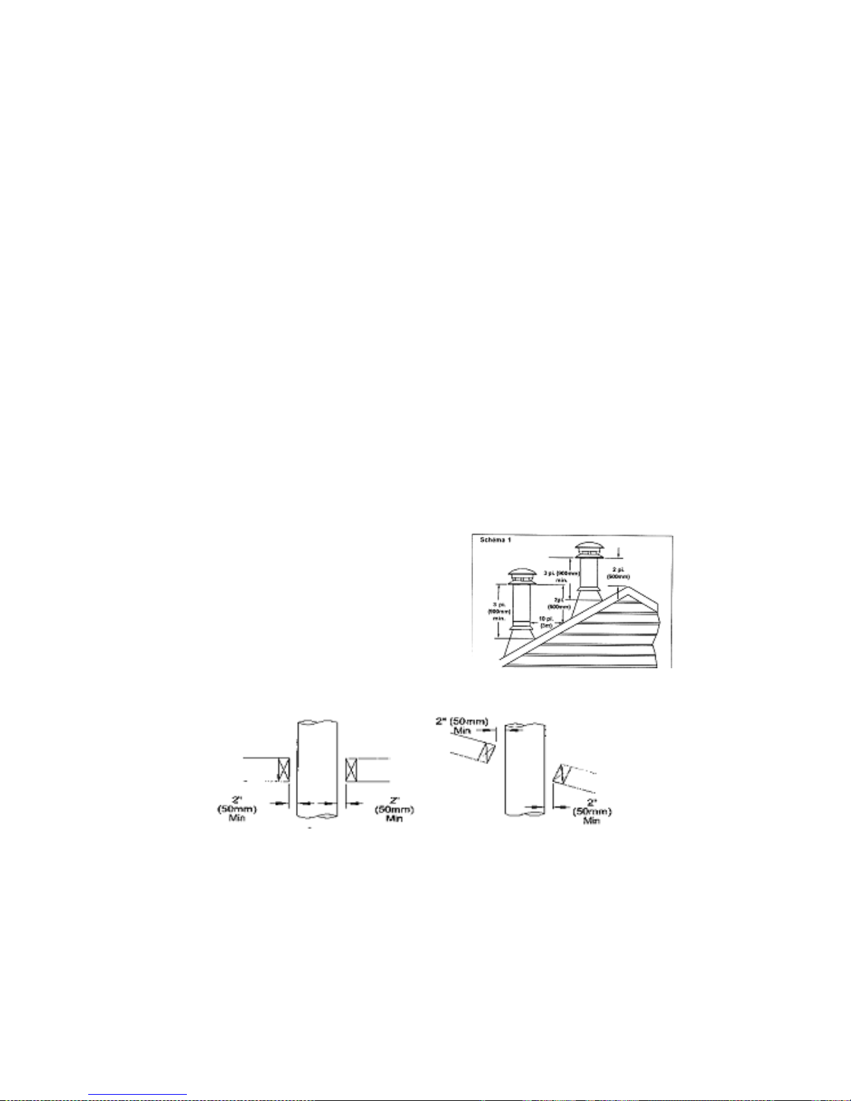
The minimum height approved for the gas evacuation system is 15 feet and the fireplace
is conceived to support up to 25 feet of vertical chimney. For higher, additional supports
are required. The authorities require that the chimney has at least 1m (3ft) over the
highest point where it passes through the roof, and at least 609mm (2ft) over any point of
the building from a distance of 10 ft. Security bridles or stainless steel screws must be
used on every section which forms an interior joint.
In addition of the owner’s manual, always refer to the instructions of the chimney
manufacturer.
C
HIMNEY FRAME DETAILS
Take the time to carefully plan the installation of your chimney. Draw and frame the
opening and be sure that the 50 mm (2 ft) minimum clearance of any combustible
material is respected. Every opening must be right and well aligned. For an angle roof,
be sure that the dimensions are calculated horizontally.
Maximum chimney height: 35 feet.
Security bridles or stainless steel screws should be used on every interior joint. Security
bridles should be used on every section forming an interior joint.
Page 10
7
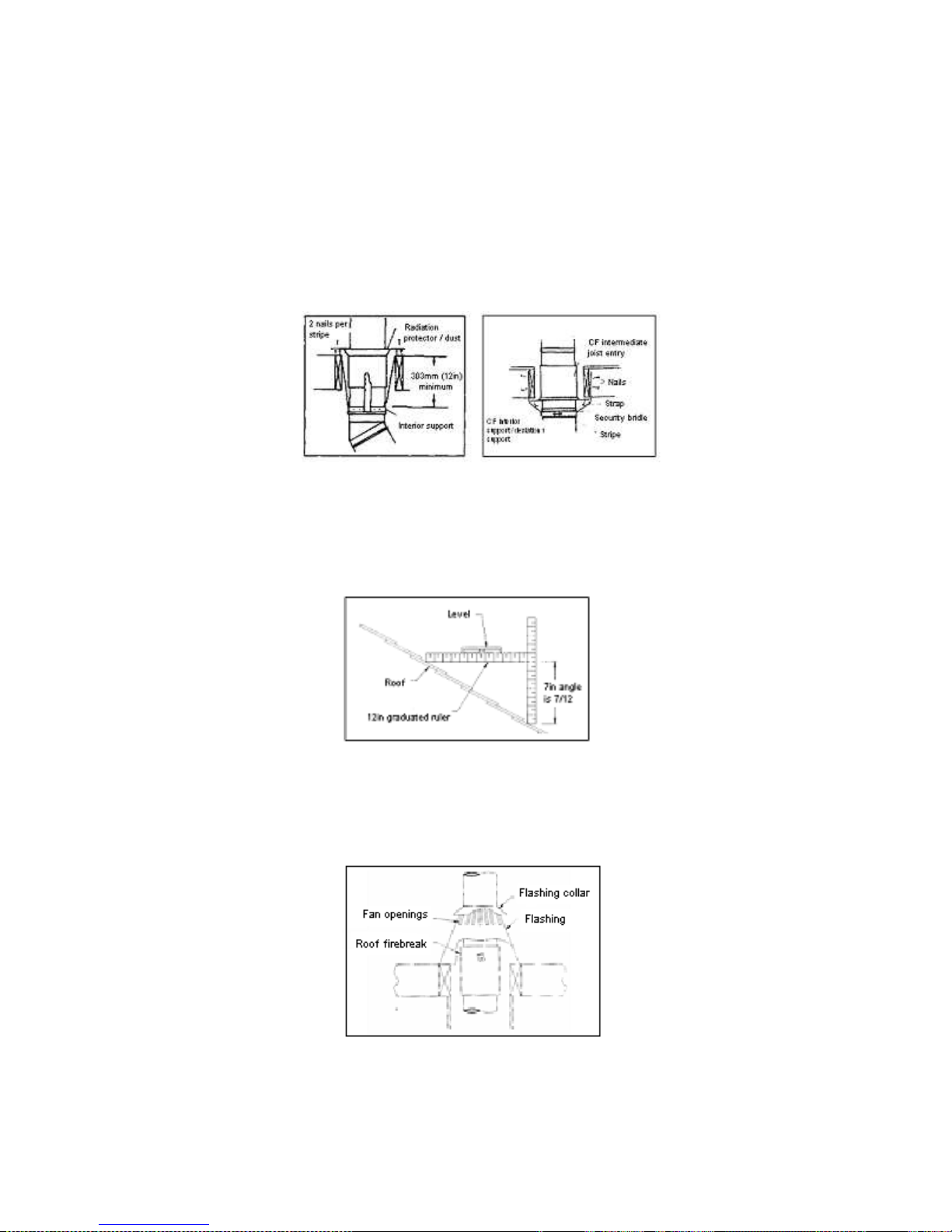
INTERMEDIATE JOIST ENTRY CF
(Selkirk CF model)
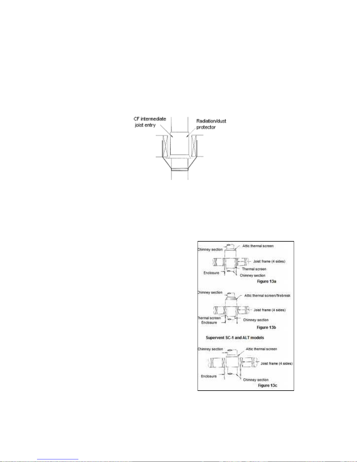
The intermediate joist entry CF is used at any joist level, except on an opened attic. It
must be installed from the base to the top with 1 ½ inches screws and should not be cut.
A
TTIC THERMAL SCREEN INSTALLATION
(JSC, SPR, SC-1 and ALT models)
An isolation protector for the attic thermal screen
must be installed where the chimney passes from
a room to a closed and superior attic. It is
conceived to keep the isolations far from the
chimney and will protect the isolations up to
250mm (10 ft) depth. In Canada, the attic thermal
screen must be installed with a firebreak like
illustrated on figure 13a.
Page 11
8
I
NSTALLATION OF THE RADIANT FIREBREAK
(Supervent JSC and SPR models)
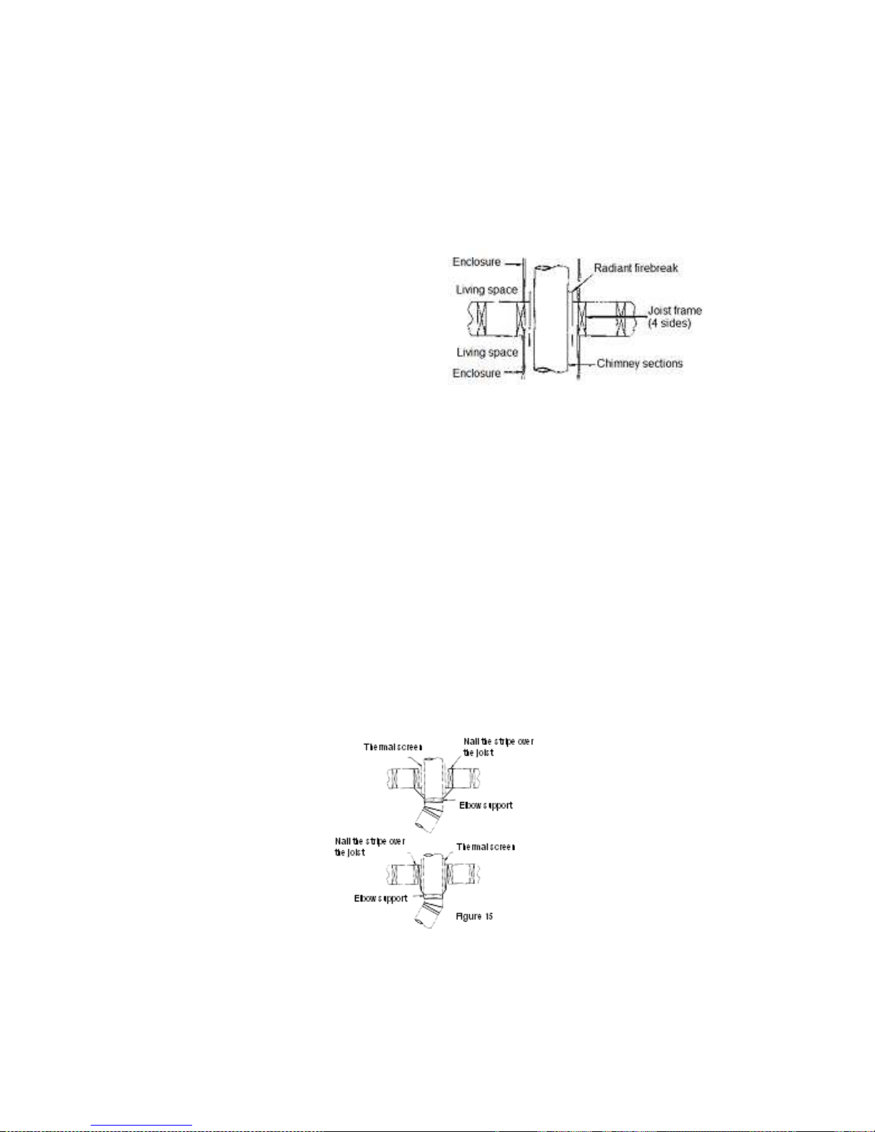
The radiant firebreak must be installed where the chimney passes through a floor or a
ceiling to another room. The radiant firebreak was tested and approved to be installed
over or under the joist.
If the radiant firebreak is installed over the
joist, be sure that there is no isolation or
other combustible up to 50mm (2 inches)
minimum clearance surrounding the
chimney. It includes spaces for the air
between the firebreak and the joist.
I
NSTALLATION OF ELBOWS
(JSC, SS Plus, SC-1, SPR, ALT and CF models)
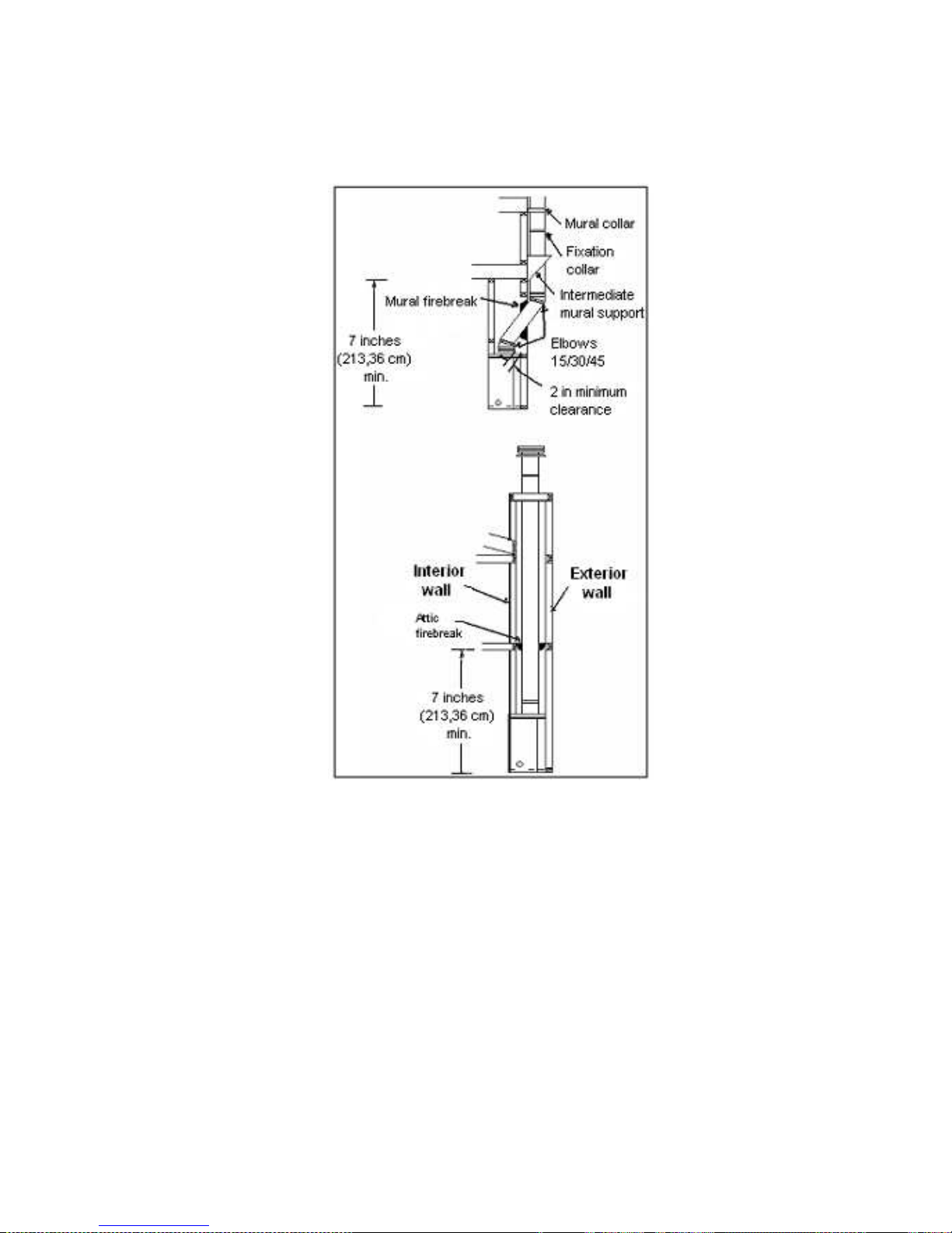
For derivation installation with a chimney, a maximum of 2 elbows of 45o and 2 elbows
of 15o or 4 elbows of 30o can be used. During the installation of the elbows, be sure to
give additional support for the deviated sections in order to avoid any excessive pressure
on the connected elbows.
Never install an elbow in a joist zone. Chimney sections must pass through joist frame
vertically.
Install an elbow support immediately over the highest elbow. Fix the support stripes to
the chimney by installing eight metal screws into the holes. Each elbow support will
maintain up to 9m (30ft) of chimney.
See figure 15.
Page 12
9
I
NSTALLATION OF THE EXTERIOR CHIMNEY
(SS Plus, JSC and SPR models)
For mural installations as illustrated, an intermediate mural support is required
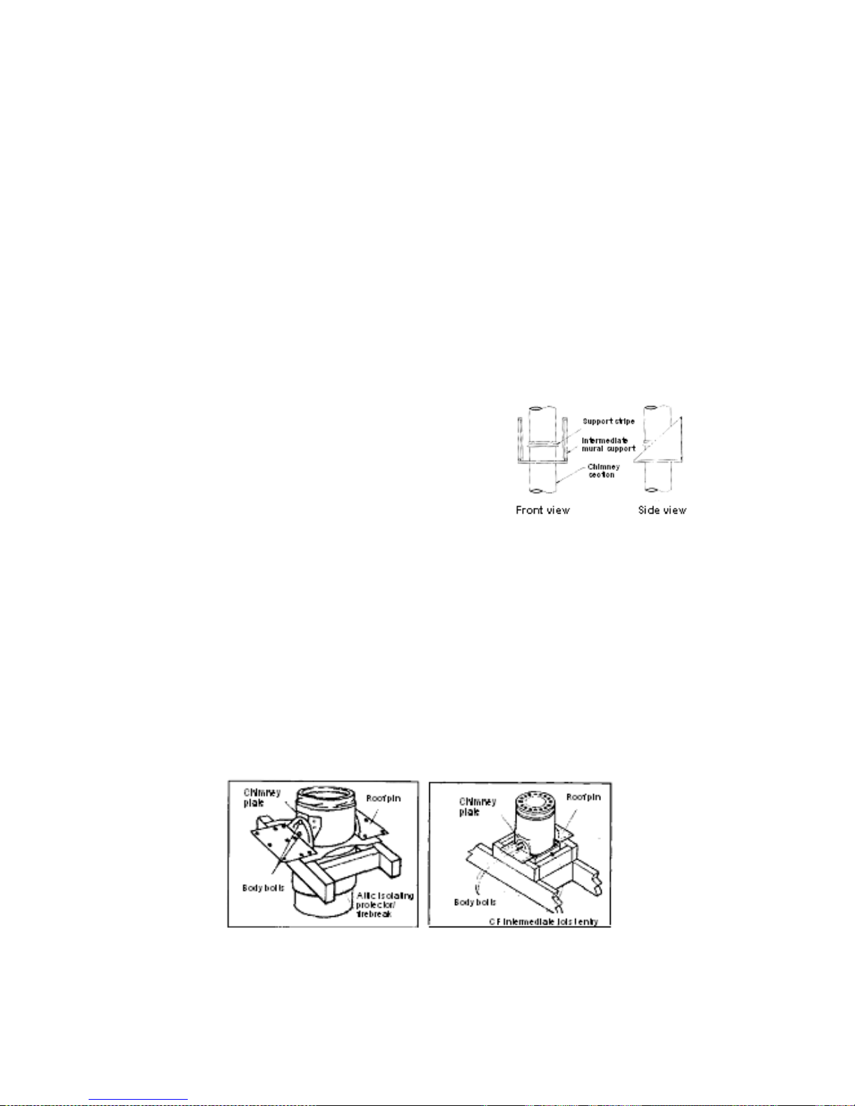
immediately over the second elbow, which will support up to 10m (30ft) of chimney.
Install a chimney section on the second elbow and fix it with a security bridle (SS Plus)
or a fixation collar (SC et SPR). Assemble the intermediate mural support with the bolts
and slide the assembly over the section you just installed. Fix the mural support on the
wall with four (4) screws of ¼ x 2 inches, so that the hole will be in the middle of the
chimney section. Install de support stripe around the chimney so that it is firmly against
the support plate and that it supports the chimney weight. Install four (4) stainless steel
screws into the exterior girdle of the chimney, through the holes in the support stripe.
Stripes or mural collars must be installed at a distance
of 2,4m (8ft) over the intermediate mural support.
With a nut and a bolt, fix the mural stripe around the
chimney section. Then, fix the stripe on the wall with
two spiraled nails 6d (3 inches) or bolts for masonry
walls.
CF
ROOF SUPPORT
CF roof support can be used with CF or SS chimney. The roof support must be located
over the joists and installed after the installation of the radiant/dust (SS model) or of the
intermediate joist entry (CF model) (if required). Install two body bolts per chimney plate
into the squared holes. Fold the plate to follow the chimney curve. By using the plate as a
guide, drill holes of 3/32 inches in the cladding. Attach the plates with the stainless steel
screws. Attach the roof clips to the chimney plates by using the body bolts already in
place, adjust and tighten. Screw the plate to the joist with six (6) big wood screws by
clips. The supports can support up to 9m (30ft) of chimney, of which 6m (20ft) can be
suspended.
Page 13
10
CF
INTERIOR SUPPORT / DEVIATION SUPPORT
The CF interior support / deviation support can be placed under an intermediate joist
entry or an attic isolation protection/firebreak. The interior support stripe of the interior
support must be attached under a security bridle and tighten. The straps must then be
placed along the exterior of the joists nailed 1 ½ inches nails, two by strap.
I
NSTALLATION OF THE ROOF FLASHING
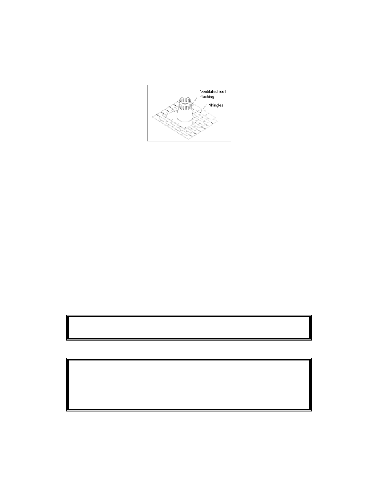
1. Be sure to have the good roof flashing. Verify the angle of your roof with a level and
two graduated rulers or with a measure card for roof angles. See drawing.
2. A firebreak is necessary only when the chimney is partitioned in an attic. The radiant
firebreak must be installed starting at the top of the joist and must be supported by the
two “L” supports on the sides. Make sure that the chimney is well balanced. Nail the roof
firebreak through the supports before the installation of the roof flashing.
Page 14
11
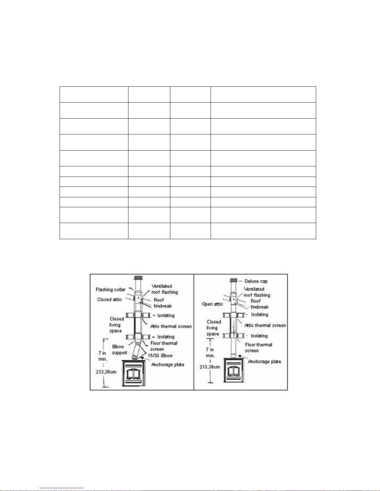
3. Slide the roof flashing over the chimney. Place the superior border of the flashing plate
under the shingles. Place the two sides and the inferior border over the shingles. See
drawing.
4. Square the flashing plate and nail it on the roof by using 12 nails with neoprene rings
or cover the heads with a waterproof mastic.
5. Roll up the flashing collar around the chimney over the flashing and fix the ends
together with the nut and the bolt without tighten. Slide the flashing collar on the
chimney until it touches the flashing guides. Tighten the nuts and the bolt and seal the
flashing collar to the chimney with a non combustible mastic.
6. The flashing and the collar should be painted to look like the roof shingles. Their lives
will be extended and the appearance of the installation improved. Clean, prepare and
paint it with appropriate products.
7. Continue to add chimney sections until you acquire the desired length. See the
chimney manufacturer's instructions
8. Install a hat (regular or luxury model) and tighten in place by turning it to the right
until it is hermetic.
9. If the chimney extends over 2m (6 ft) over the roof, roof shrouds will be necessary.
The JURGK-1 model suits to this installation. The support stripe must be stapled around
the chimney and the two legs bolted to the chimney.
NOTICE : LIFT THE SHINGLES AND NAIL THE SUPERIOR
BORDER OF THE FLASHING PLATE TO THE ROOF.
THEN, GLUE THE SHINGLES WITH A WATERPROOF
MASTIC.
WARNING : DO NOT BLOCK THE FAN OPENINGS IN THE
FLASHING.
Page 15
12
B
LOWHOLE SYSTEMS AUTHORIZED
Manufacturer Model
Chimney
depth
Necessary component with the
Evolution fireplace
Cheminée Sécuritée
Int.
Secure temp
S-2100+
2
Attic firebreak (
6 RSA )
non isolated
Oliver Macleod HT 6000+ 2
Attic firebreak (
6 RSA )
non isolated
Selkirk Metalbestos
Ltd
CF Sentinel 2
Selkirk Metalbestos
Ltd
Ultra Temp 1 Roof radiant firebreak
JSC 6 RRS
Superpro ALT 2
Superpro SPR 1 Roof radiant firebreak
JSC 6 RRS
Supervent(GSW) JM 2
Supervent(GSW) JSC 1 Roof radiant firebreak
JSC 6 RRS
Simpson Dura Vent
Dura Plus
HTC
2
Simpson Dura Vent Duratech 1
Roof firebreak C9089 (for 6" and
7")
*Every chimney should be installed with ventilated flashings.
Page 16
13
Page 17
14
EXTERIOR AIR CANALIZATION
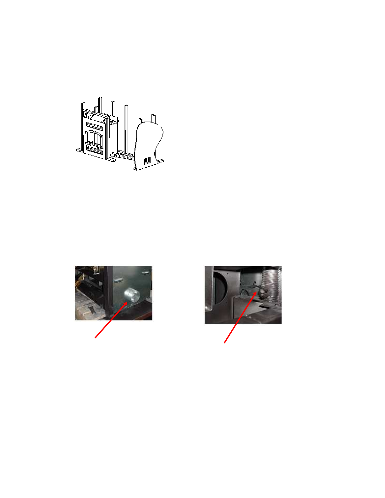
Install the exterior air canalization high
enough so that it will not be block by the snow
and plan an anti-rodent grid. You should not
take the air from a garage, a carport or an attic.
Your Evolution fireplace can bring exterior air
to your fireplace. The maximum length of the
4" isolated conduct is of 20 feet. If your
conduct is longer, widen the diameter to 5
inches. It can be installed over or under the
floor level of your fireplace. The conduct
should not exceed 12 feet of vertical climb
from the base of your fireplace.
Insert the isolated flexible conduct on the exterior air access adaptor and on the air
admission connector. On both ends, bring back the isolation and plastic cladding on the
flexible conduct. Fix each extremity with metal screws and apply aluminium tape over
the conduct in order to seal this part.
The Evolution fireplace can use exterior or interior air. To use exterior air, open the
sliding door on the inferior right side of the fireplace. To access this door, open the
inferior blinds and slide your hand to the sliding door handle.
Admission air connector Sliding door handle
Page 18
15
INTERNAL BLOWER (FANS AND THERMODISC)
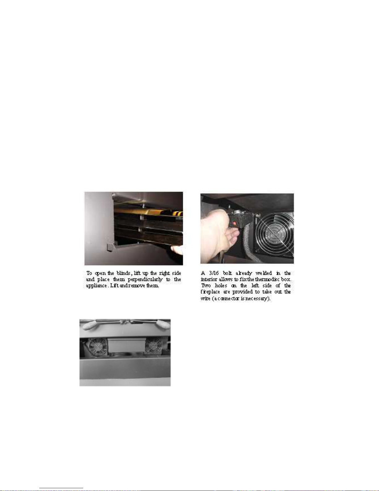
You can add an internal blower to your Evolution fireplace. This kit is a standard at J.A.
Roby inc. It includes two fans and a thermocouple lightly noisy and easy to install. The
connection must be done by a qualified electrician. The internal and central blower
wiring must be installed during the construction of the frame so that the cords can be
easily hide. The internal blower kit can be the same as used on other J.A. Roby products.
However, when used into the Evolution, you must cut the plug and use a junction box.
Installation : Open the inferior blinds, fix a square fan (with grid) of 4 in by 4 in of
each side of the ashtray with the screws given in the blower kit. The
thermodisc box must be installed at the left along the exterior side and the
junction box to the right on the floor, where you find the air entry control.
See pictures.
Page 19
16
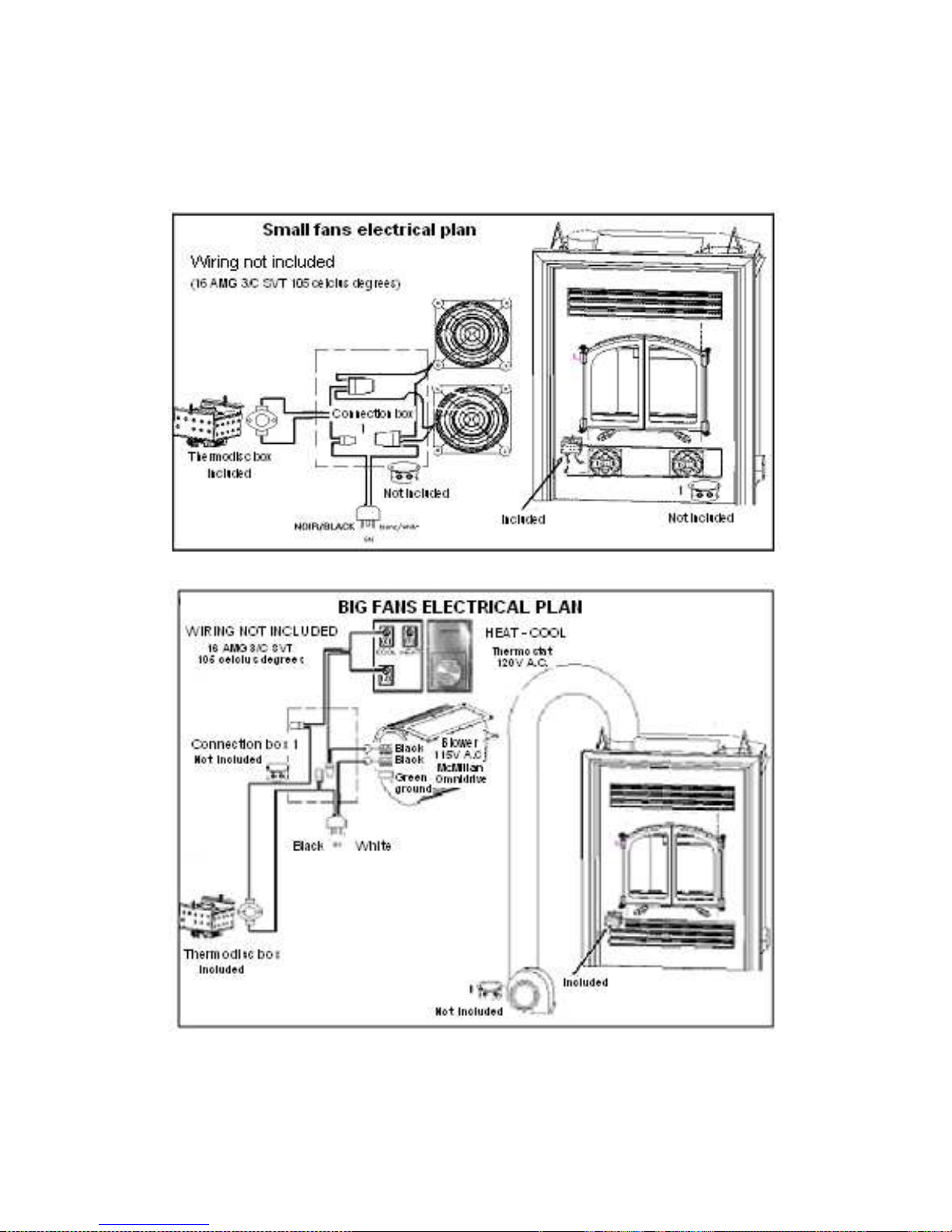
ELECTRICAL PLAN OF THE FANS
Wiring must be done by a qualified electrician.
Page 20
17
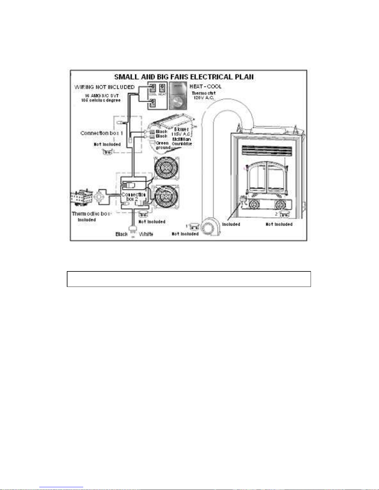
W
IRING MUST BE DONE BY A QUALIFIED ELECTRICIAN
.
Page 21
18
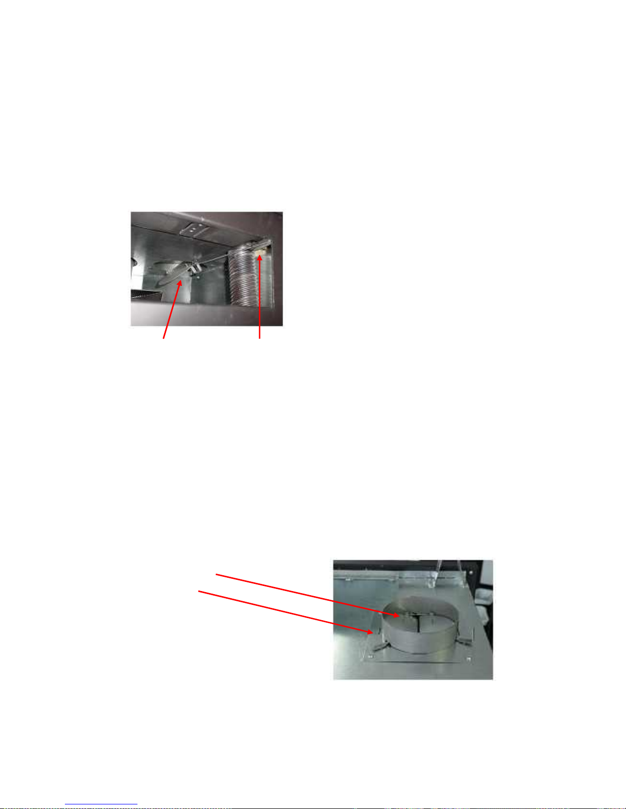
BLOWHOLE BY NATURAL CONVECTION
Blowhole by natural convection can deliver air to a superior level or an adjacent room
without needing a blower. This system can be used jointly with optional blowers. Adjust
manually the register to your needs. The blowhole system by natural convection can be
used in position "open" or "close".
The blowhole by natural convection kit
includes:
o Starting collar.
o Decorative grid with the retain
collar.
o 5' isolated flexible pipe (200Of)
(SIS).
o Register with a rod.
NOTES: Do not install a back draft valve on the blowhole system by natural convection.
In the fireplace fitting, each conduct must be an isolated flexible pipe (SIS). At
the exterior of the fitting, each conduct must be an isolated pipe with a plastic
envelope (RIG).
You must never bring downstairs an hot air canalization. It must always be
ascending.
CENTRAL BLOWER
o Blower.
o Back draft valve.
o Starting collar.
o Finishing grid.
o Thermodisc.
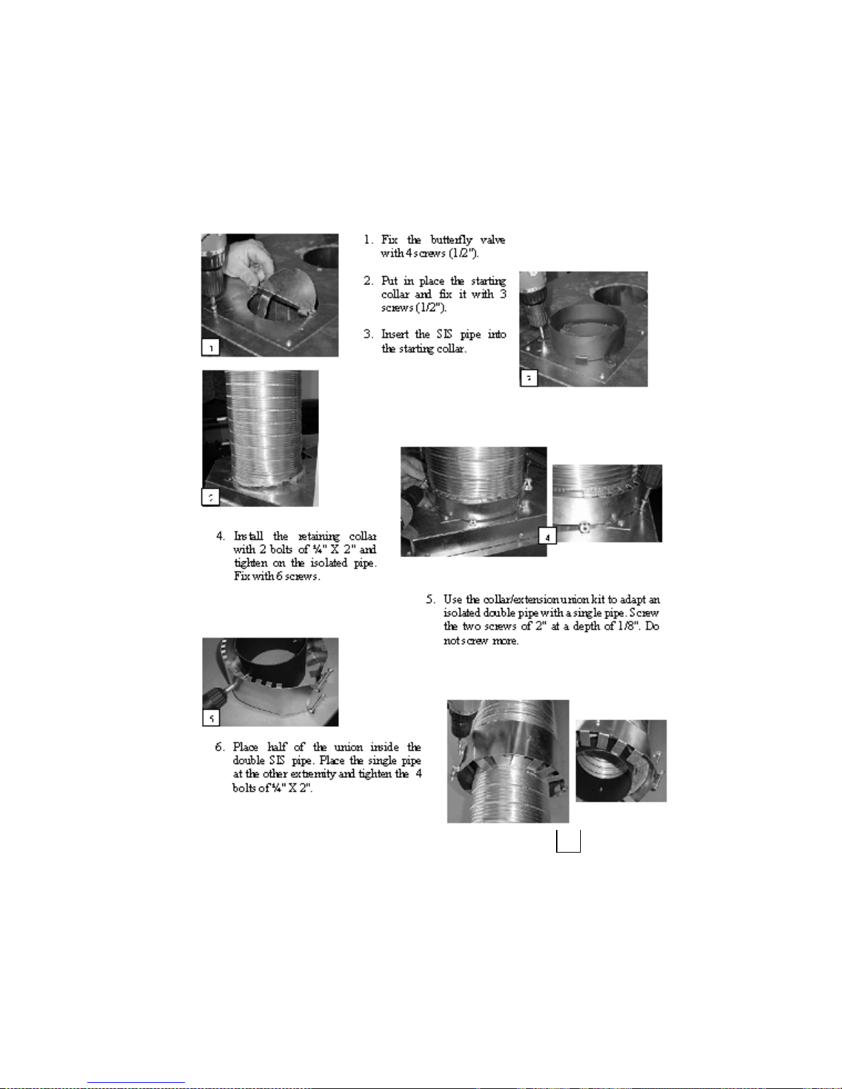
o Kit union / collar (ATCUP)
o 8 feet pipe (5' SIS and 3' S).
Control rod Register
Page 22

19
The Evolution fireplace has two air exits on the top of the appliance. When you want to
plug the central blower, use the left exit (when you face the fireplace). The right one is
only for the blowhole by natural convection. The fan system must not end in the attic.
o To begin the installation of the blower kit, remove the metallic circle on the left top of
the appliance. Remove the wool round, open the top blinds, remove the metallic cap
from the same hole but this time, from the interior.
o Install the back draft valve, centre on the top and fix it with 4 screws.
o Install one starting collar and fix it with 4 screws.
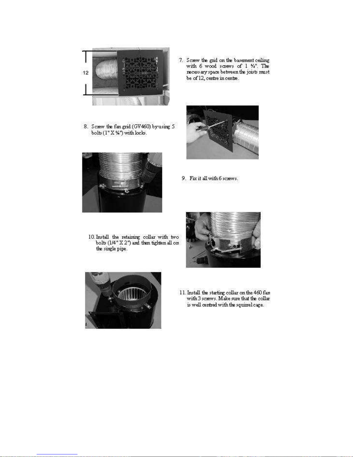
o Install the blower at a place where it will be easy to inspect and maintain. If you want
to install only one grid in order to transfer the warmth of your Evolution to a superior
floor, fix the floor grid to the fan and fix it between the joists. If you want to dispense
hot air to several rooms, fix the exit adaptor of the rectangular fan for round pipes and
continue with round pipes. This last part can be a flexible pipe isolated with a plastic
envelope or a fan conduct.
NOTE: If you do not install the back draft valve with the central blower, it could
seriously compromise the security of your installation.
Page 23
20
INSTALLATION OF THE 460 CFM FAN
6
Page 24
21
Page 25
22
EXTRUSION
Your Evolution fireplace is delivered with an extrusion which allows a good quality of
finishing and is easy of installation. When the gypsum wall is finished, you only have to
slide the extrusion on each side of the fireplace. Then, insert the superior part and the
finishing is completed.
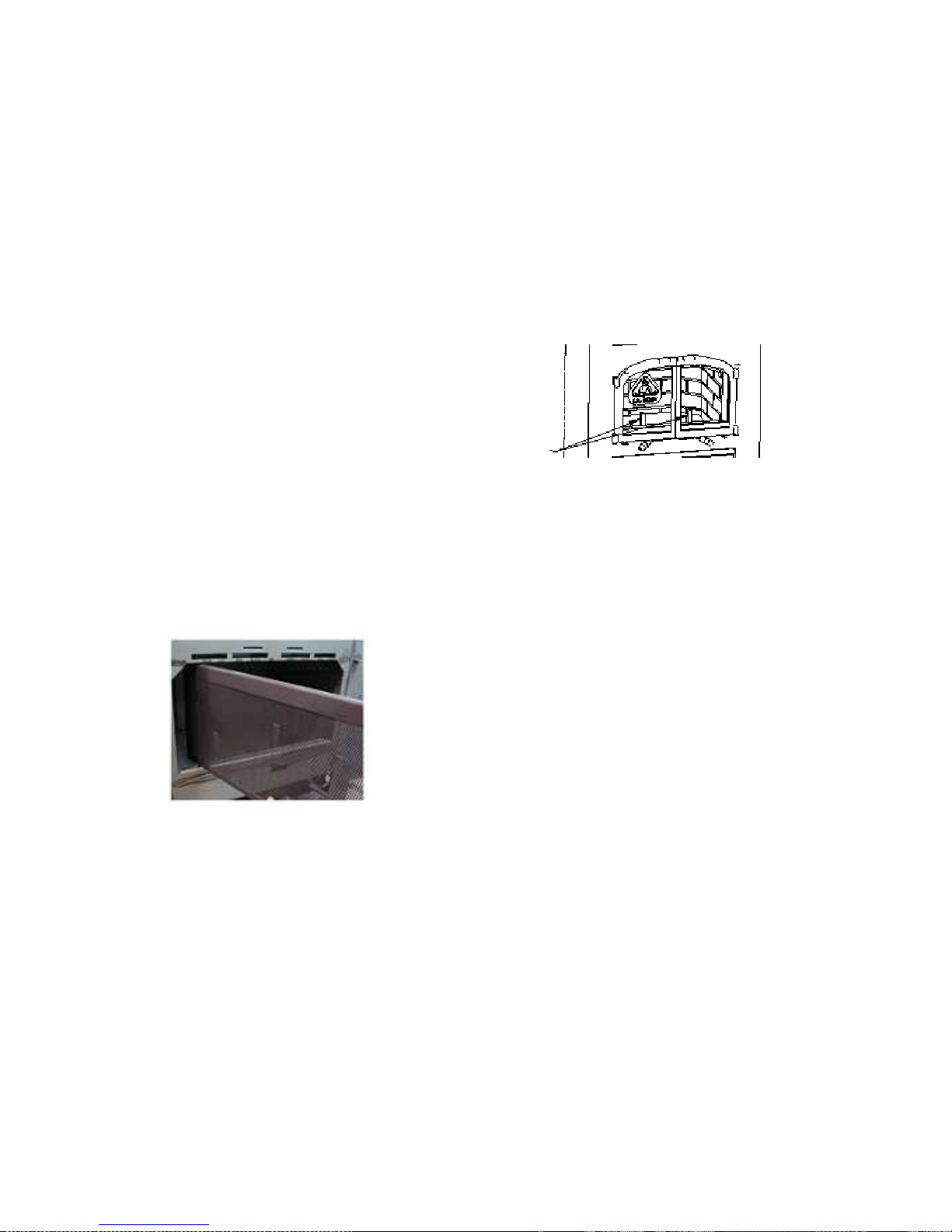
INSTALLATION OF THE FIREBRICKS
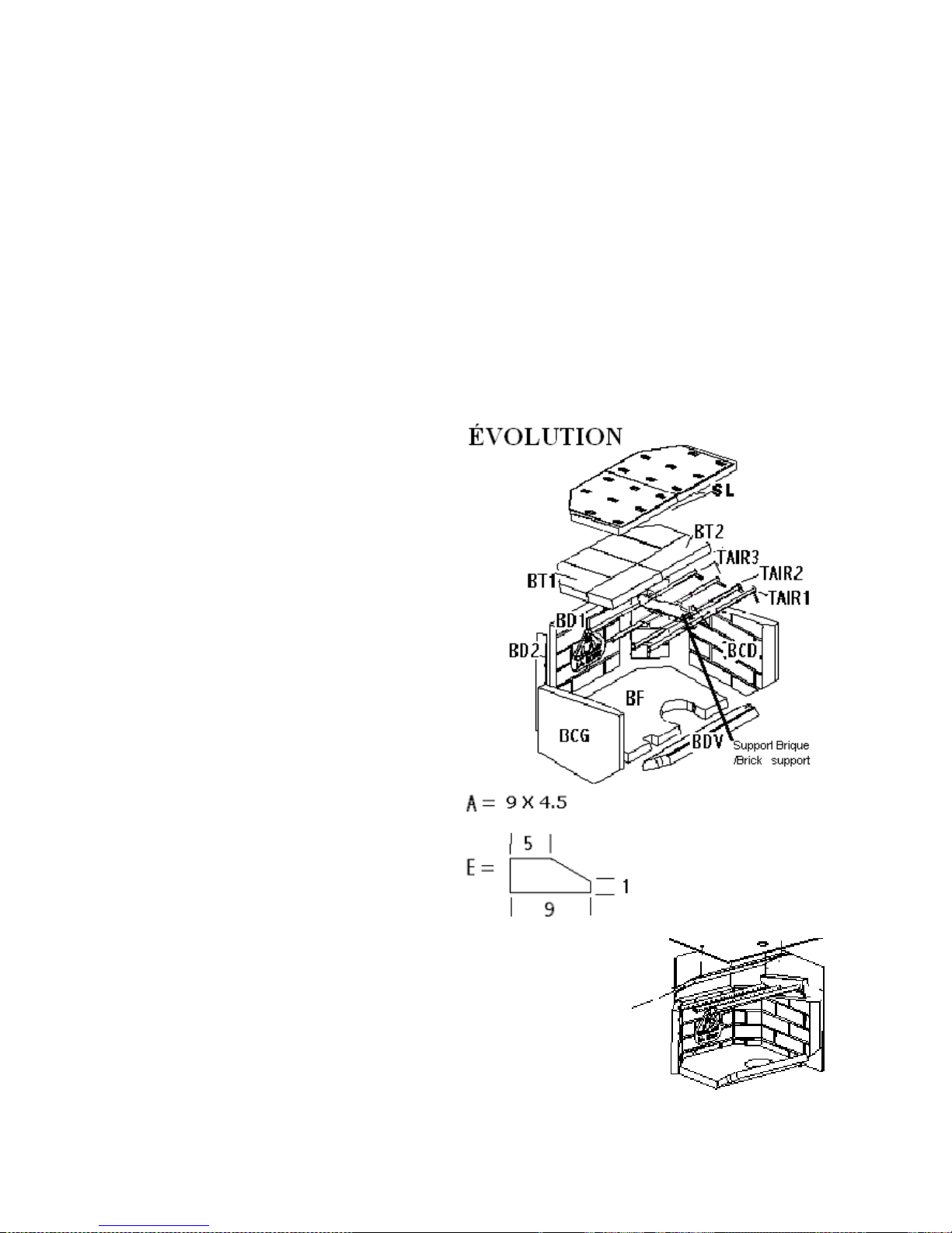
Your Evolution fireplace includes a
firebricks kit. They must be installed
as follow:
- Remove the front pipe.
- Place two metal pieces (SL) and
ceramic wool over the brick.
- Install the 2 firebricks of the top
(BT1), then place the 4 others
(BT2).
- Replace the pipe and fix it with
screws.
- Place the bricks at the back (BD1),
followed by the two angled bricks
(BD2).
- Then, install the left and the right
side bricks (BCG et BCD), followed
by the bottom brick (BF).
- To finish with, place the angled
brick at the front.
To remove the deflector, remove the
pipes, the bricks supports and the
ceiling bricks of the combustion
chamber, then unscrew the 2 bolts
retaining it. It is not necessary the remove the deflector when
sweeping.
Page 26
23
DOORS ADJUSTMENT
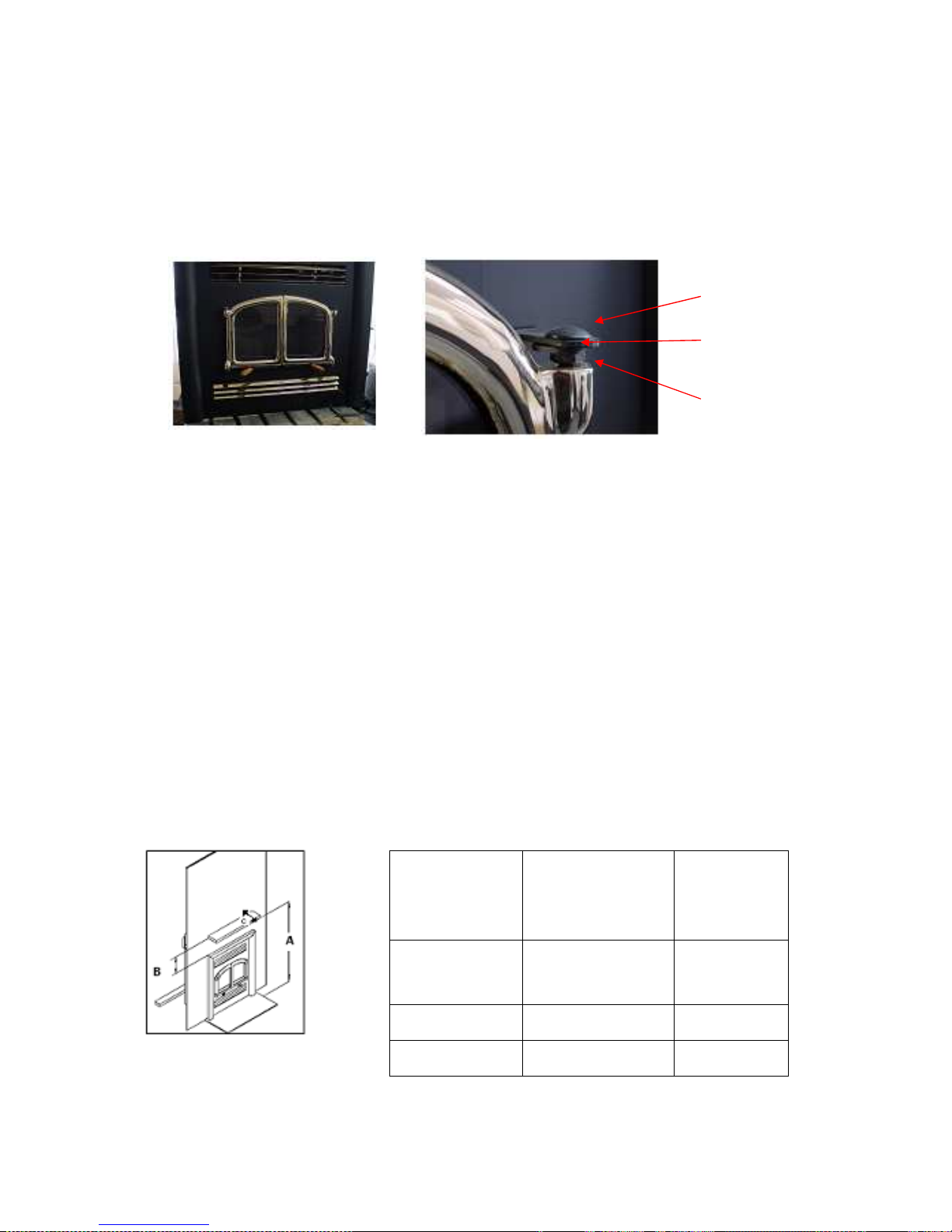
Your Evolution fireplace is a model with two cast iron doors. Each door can be adjusted
(height, width and depth). To adjust, unscrew the four nuts, close the left door first then
the right one. Adjust the arc over the doors to align it and the centre of the two doors.
Firmly maintain the two doors against the facade and tighten the 4 nuts. You have an
adjustment screw under the centre of the two doors. The more screwed it is, the more
tighten the doors will be on the front.
For the single door option, firmly maintain the door against the front and tighten the 2
nuts (left side).
SHELF
A masonry shelf or of any other non combustible material can be installed directly over
the fireplace extrusion. If you use a shelf made of combustible material, the height from
the base of the fireplace must be at least of 48" for a shelf depth of 6", or of 52" for a
depth of 8", or of 54" for a depth of 10".
Minimum distance
from the base to
the shelf
(A)
Minimum distance
from the fireplace
moulding to the shelf
(B)
Maximum shelf
depth
(C)
48" (122cm) 8
3/8
" (21,5cm) 6" (16cm)
52" (132cm) 12
3/8
" (31,5cm) 8" (20,5cm)
54" (137cm) 14
3/8
" (36,5cm) 10" (25,5cm)
Bolt
Locking ring
Nut
Page 27
24
LIGHTING
Before lighting the first fire, be sure to clean every dirt or fingerprints if you don't want to
permanently mark your fireplace.
To light a fire, place newspapers and small wood. Then, add small wood logs. Light the
fire and let the door slightly open. Once the fire is well lit, add bigger wood logs and
close the doors.
NEVER use inflammable liquids.
N
OTE :
P
LACE THE FIRE BEHIND THE TWO
FIREDOGS
.
FIREGUARD
When the fireplace is used with doors completely open, you must use a fireguard. It will
avoid burning your floor. You should not let the fireplace without supervision when using
it with a fireguard.
T
HE UTILIZATION OF THE FIREGUARD IS AUTHORIZED
ONLY IF INSTALLED WITH A
2100
0
CHIMNEY ACCORDING
TO THE CAN\ULC-S
629
NORM. THE
1800
0
CHIMNEY
APPROVED ACCORDING TO THE ULC-S
604
NORM IS NOT
ACCEPTED FOR AN OPEN DOOR UTILIZATION WITH A
FIREGUARD
.
To install the fireguard, place it perpendicular to the front of the appliance. Insert the top
pin in the provided hole and then, insert the bottom pin. Always use incombustible gloves
or a poker to open the fireguard.
You should not let the fireguard when the doors are closed and the appliance in function.
It could burn the grilling.
Page 28

25
PREVENTIVE MEASURES AND MAINTENANCE
Verify the accumulation of creosote every week that you use the appliance until you
know at which frequency it must be cleaned (minimum once per year). Remove every
creosote deposit in order to prevent chimney fires. A sweeping is recommended if there is
an accumulation of 1/8 inches. To sweep, you must remove the ceiling pipe located at the
front of the combustion chamber, the bricks and the ceramic wool. When the sweeping is
finished, put all back.
At the end of each season, verify the air tightness joints. Replace if damaged. An air
infiltration by a non air tightness joint could be the cause of several inconveniences.
Before lighting the first fire, clean the gold plated surfaces using a very soft rag
moistened with water. Do not use a paper towel to clean it. If they are not erased before
the first fire, the fingerprints and other marks could stain these surfaces permanently.
An extended combustion at a high temperature with the door slightly open or the ashes
cap not properly positioned could cause a permanent decoloration of the gold plated
doors.
The Evolution fireplace is equipped with an ashtray allowing to clean the firebox easily.
Open the doors, remove the ashes cap and, with a poker, wipe out the ashes (be sure that
the ashtray is in place). When the ashtray is full, open the down blinds, remove the
ashtray and place the ashes in a secure box (metallic box with a cap). Never empty the
ashes while hot. The ashtray was not conceived to receive hot ashes.
Glass maintenance
A hot fire will maintain the glass clean. If your glass becomes dirty, the cause might be:
• A too slow combustion (combustion not hot enough).
• Utilization of green or moist wood.
• Lack of draught of the chimney.
• Be sure that there is enough air to realise a complete combustion.
• Do not build the fire too close from the glasses.
• Do not knock on the doors in order to avoid the breaking of the glasses.
To clean the glasses, J.A. Roby Inc. recommends using products sold for this purpose or
an oven cleaner. Avoid cleaning with abrasives or when the glass is hot.
Page 29

26
In case of a glass replacement:
• Remove the screws and supports retaining the glasses.
• Remove the broken glasses.
• Envelope the frame of the new glass with a fibre glass joint.
• Replace the glass.
• Replace the screws and the support.
R
EPLACE THE BROKEN GLASSES BY
VITROCERAMICS
GLASSES OF 5MM
.
DO NOT USE SUBSTITUTES !
INTERCHANGEABLES PARTS LIST
- Firebricks
- Back bricks (BD1)
- Bottom angled bricks (BD2)
- Left side bricks (BCG)
- Right side bricks (BCD)
- Bottom bricks (BF)
- Top bricks (BT1)
- Top bricks (BT2)
- Metallic parts and ceramic wool (SL)
- Front bricks (BDV)
- Bolt kit for the door adjustment (KB) (Bolt, locking ring, nut)
- Internal blower (VENT)
- 1 fan (1 VENT)
- Fan grid (GV460)
- 460 CFM fan (VENT460)
- Retaining collar (CR)
- Decorative grid with retaining collar (GDVCR)
Page 30

27
- Register (RCN)
- Starting collar (ATCCD)
- Back draft (ATCVAR)
- Control rod (TRCN)
- Collar / Extending union kit (ATCUP)
- Inversed thermostat (ATCT)
- Exit adaptor (ATCAS)
- Front frame (ATCCF1 ) (ATCCF2 ) (ATCCF3 )
- Blinds (ATCPERO) (ATCPERC) (ATCPERN) (ATCPERE)
- Cast iron door (EVPN) (EVPO) (EVPC) (EVPE)
- Cast iron door (EV1PN) (EV1PO) (EV1PC)
- Glass (VIEV-2) (VIEV-1)
- Single pipe
- SIS pipe
- RIG pipe
*T
O ORDER PARTS, PLEASE CONTACT YOUR AUTHORIZED RETAILER
.
Page 31
28
STOVES & FIREPLACES
WARRANTY
J. A. ROBY LIMITED LIFE WARRANTY – WOOD BURNING STOVES & FIREPLACES
J. A. ROBY’s warranty only applies to original buyer and is non-transferable. This warranty covers brand new products
only, which have not been altered, modified nor repaired since shipment from factory. The products covered by this
warranty must be manufactured after review date indicated at the bottom of page. Proof of purchase (dated bill of sale),
model name and serial number must be supplied when making any warranty claim to your J. A. ROBY dealer.
Registered your warranty is not required.
The appliance must be installed by an authorized service technician or contractor. Installation must be done in
accordance with the installation instructions included with the product and all local and national building and fire
codes. Any service call related to an improper installation is not covered by this warranty. This warranty applies to
normal residential use only. This limited warranty does not cover damages caused by misuse, improper installation,
lack of maintenance, accident during transportation, alterations, power failure, venting problems, downdrafts, abuse,
over firing or neglect. Operating the appliance on high for extended periods of time is neglect. Any defect or damage
caused by the use of unauthorized parts or others than original parts void this warranty.
This limited warranty does not cover any scratch, corrosion, warping or discoloration. The manufacturer may require
that defective products be returned and/or that digital pictures be provided to support the claim. Returned products are
to be shipped prepaid to the manufacturer for investigation. If a product is found to be defective, the manufacturer will
repair or replace such defect. The transportation fees to ship back the product to the purchaser will be paid by the
manufacturer2. The external labour fees related to warranty repair are not covered. The manufacturer may at its
discretion, decide to repair or replace any part or unit after inspection and investigation of the defect. The manufacturer
may at its discretion, fully discharge all obligations with respect to this warranty by refunding to the original warranted
purchaser the wholesale price of any warranted but defective part (s). The manufacturer shall not in no event be liable
for any special, indirect or consequential damages of any nature whatsoever which exceeds the original purchase price
of the product. All parts replaced under this limited life warranty are subject to a single claim.
Any damage to the appliance, combustion chamber, heat exchanger, enameled cast iron cooking plate or other
components due to water, weather damage, long periods of dampness, condensation, damaging chemical or cleaner will
not be the responsibility of J. A. ROBY. Failure of any components which is attributed to poor maintenance, is not
warrantable and will not be covered by this policy. J.A. ROBY neither assumes, nor authorizes any third party to
assume, on its behalf, any other liabilities with respect to the sale of this product.
The manufacture of your new appliance and the following materials are warranted against defects as mentioned below:
WARRANTY DESCRIPTION 100%
50% current
retail price
Ashtray, handles, doors and cast iron legs
Life
Combustion chamber 5 years
From 5 years
to life
Secondary air tubes
5 years
Heat exchanger 2 years
From 2 years
to life
Switches, thermodisc, wiring and electrical components, standard blowers
and rheostat
2 years
Tempered glass, optional blower and gasketing
1 year
Ceramic glass (thermal brea
kage only
1
) 1 year
Replacement parts (with proof of purchase)
90 days
Due to on-doing product improvements, all specifications and design are subject to change without prior notice.
Before shipping your unit or defective component to our plant, you must obtain from J. A. ROBY dealer an
authorization number. Any merchandise shipped to our plant without authorization will be refused
automatically and returned to sender.
1= Digital pictures required 2= Shipping cost are not covered outside CANADA
Review oct. 2014
Page 32
29
 Loading...