

Last change by:
MT, 14.12.2011
Checked by:
WH, 10.02.2012
Document status:
APPROVED
Document Nr.:
119048
Document Revision:
003
Frequency Measurement and Switching Instruments
T411 / T412
Operating Instructions
This is a translation of the master document 119047 Rev 003
Single Channel Tachometer with Display and 0/4-20mA Output
• T411.00: Part No.: 383Z-05318 (+14V Sensor supply )
• T411.03: Part No.: 383Z-05595 (+5V Sensor supply )
Single Channel Tachometer with Display and 0/2-10V Output
• T412.00: Part No.: 383Z-05319 (+14V Sensor supply)
• T412.03: Part No.: 383Z-05596 (+5V Sensor supply)
JAQUET AG , Thannerstrasse 15, CH-4009 Basel
Tel. +41 61 306 88 22 Fax +41 61 306 88 18 E-Mail: info@jaquet.com

Operating Instructions T411 / T412 JAQUET AG
Revision: 003 2/27
Contents:
1 SAFETY INSTRUCTIONS 4
2 PRODUCT FEATURES 4
3 SPECIFICATIONS 5
3.1 General 5
3.2 Inputs 6
3.2.1 Analog Sensor connection (Sign) 6
3.2.2 Digital Sensor connection (IQ) 7
3.2.3 Binary input 7
3.3 Outputs 8
3.3.1 Analog output 8
3.3.2 Relay 9
3.3.3 Open Collector Output 9
3.4 Data communication 9
3.4.1 Serial interface (RS 232) 9
3.5 Environment 10
3.5.1 Climatic conditions 10
3.5.2 Electromagnetic immunity 10
3.5.3 Other Standards 10
4 PRINCIPLE OF OPERATION 11
4.1 General 11
4.2 Machine factor 12
4.2.1 Known (Measured) 12
4.2.2 Calculated 12
4.2.3 Displaying other physical values 12
5 INSTALLATION 13
6 CONNNECTIONS 13
6.1 Front view 13
6.2 T411 terminals 14
6.3 T412 Terminals 14
7 HARDWARE CONFIGURATION 15
7.1 Analog Sensor input (Sign) 15
7.2 Digital Sensor input (IQ) 15
8 CONFIGURATION WITH PC SOFTWARE 16
8.1 Software concept 16
8.2 PC communications 16
8.3 PC Software settings 16
8.3.1 Interface (Settings Interface) 16
8.3.2 Display Interval (Settings Display Interval) 16
8.4 Parameter list and ranges 17
8.5 Parameters 18
8.5.1 System parameters (Configuration System) 18
8.5.2 Sensor parameter (Configuration Sensor) 19
8.5.3 Analog Output (Configuration Analog Output) 19
8.5.4 Limit (Configuration Limit) 20
8.5.5 Relay parameter and selection of Parameter set (Configuration Relay control) 20

Operating Instructions T411 / T412 JAQUET AG
Revision: 003 3/27
9 OPERATING BEHAVIOR 21
9.1 Power on 21
9.1.1 Analogue Output 21
9.1.2 Relay Output 21
9.2 Measurement 21
9.2.1 The adaptive Trigger level 21
9.2.2 Signal failure 22
9.3 Functions 22
9.3.1 Limits and Window Function 22
9.3.2 Parameter set A and B 22
9.3.3 Relay hold function 22
9.3.4 Binary Input 23
9.4 Fault behavior 23
9.4.1 Sensor fault (Sensor monitoring) 23
9.4.2 System alarm 23
9.4.3 Alarm 23
9.5 Power supply interruption 23
9.6 Display adjustments 24
9.6.1 Brightness 24
9.6.2 Contrast 24
10 MECHANICAL CONSTRUCTION / HOUSING 24
11 ACCESSORIES 25
12 MAINTENANCE / REPAIR 25
13 SOFTWARE VERSIONS 25
14 WARRANTY 25
15 DECLARATION OF CONFORMITY 26
16 CONNECTION DIAGRAM T411/412 27

Operating Instructions T411 / T412 JAQUET AG
Revision: 003 4/27
1 Safety Instructions
T400 series tachometers may only be connected by trained & competent personnel.
As soon as an electrical circuit is connected that can have dangerous voltages, other
tachometer components may exhibit a dangerous potential.
(Series T400 tachometers do not themselves generate dangerous potentials)
Before opening the tachometer (Hardware configuration) the unit must be disconnected from circuits that may
exhibit dangerous potentials.
These instruments correspond to protection class I and it is therefore mandatory to earth the PE terminal.
The instructions in this operating guide must be strictly adhered to. Not doing so may cause harm to
personnel, equipment or plant.
Instruments in a doubtful condition after electrical, climatic or mechanical overload must be immediately
disconnected and returned to the manufacturer for repair.
The instruments have been developed and produced in accordance with IC-348 and left the factory in perfect
condition.
2 Product features
Series T400 tachometers measure and monitor frequencies (speed proportional values) in the range
0 to 35,000 Hz.
The following features are available:
• 1 Current or voltage output (T411 - current, T412 - voltage)
• 1 Sensor frequency output
• 1 Relay
• 2 Limits
• 2 Parameter sets – selectable via binary input
• Sensor monitoring
• System monitoring
The tachometers are configured via T400 PC configuration software.
All settings are in revolutions per minute (rpm).
4 models are available:
T411.00
Single Channel Tachometer with Display, +14V Sensor supply, Relay and 0/4-20mA
Output
383Z-05318
T412.00
Single Channel Tachometer with Display, +14V Sensor supply, Relay and 0/2-10V
Output
383Z-05319
T411.03
Single Channel Tachometer with Display, +5V Sensor supply, Relay and 0/4-20mA
Output
383Z-05595
T412.03
Single Channel Tachometer with Display, +5V Sensor supply, Relay and 0/2-10V
Output
383Z-05596
Operating Instructions T411 / T412 JAQUET AG
Revision: 003 5/27
3 Specifications
Ambient temperature + 20 °C
3.1 General
T411 - T412
Lowest measuring range
0 . . . 1.000 Hz
Highest measuring range
0 . . . 35.00 kHz
Minimum Measuring time
(Fixtime)
Selectable values: 2 / 5 / 10 / 20 / 50 / 100 / 200 / 500ms
1 / 2 / 5 Seconds.
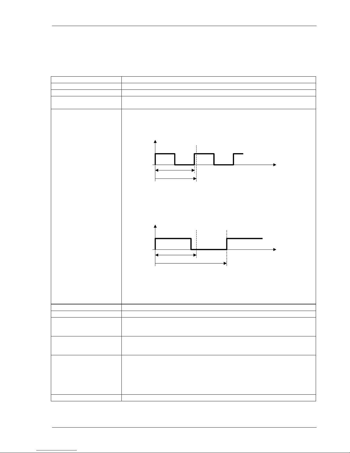
Effective Measuring time
Is based on the minimum measuring time (Fixtime) and the measured
frequency.
• Input frequency period < Fixtime
Input
frequency
End of Fixtime
Input period
Fixtime
time
typically: t
effective
= Fixtime
max: t
max
= 2 x Fixtime
• Input frequency period > Fixtime
Input
frequency
End of Fixtime
Ensuing edge
Period of input signal
Fixtime
time
max: t
max
= 2 x input frequency period
• In the event of sensor signal failure:
t
effective
= Fixtime + (2 x last input frequency period)
Resolution
0.05 %
Power supply range
10...36 VDC
Power consumption
10 V : 2.3 W
24 V : 2.6 W
36 V : 3 W
PSU failure bridging
16 V : 4 ms
24 V : 25 ms
36 V : 75 ms
Isolation
Galvanic isolation between:
• Power supply,
• Sensor input incl. sensor supply, Binary input, Serial interface
• Analog output
• Relay output
• Open collector output
Isolation voltage
700 VDC / 500VAC
Operating Instructions T411 / T412 JAQUET AG
Revision: 003 6/27
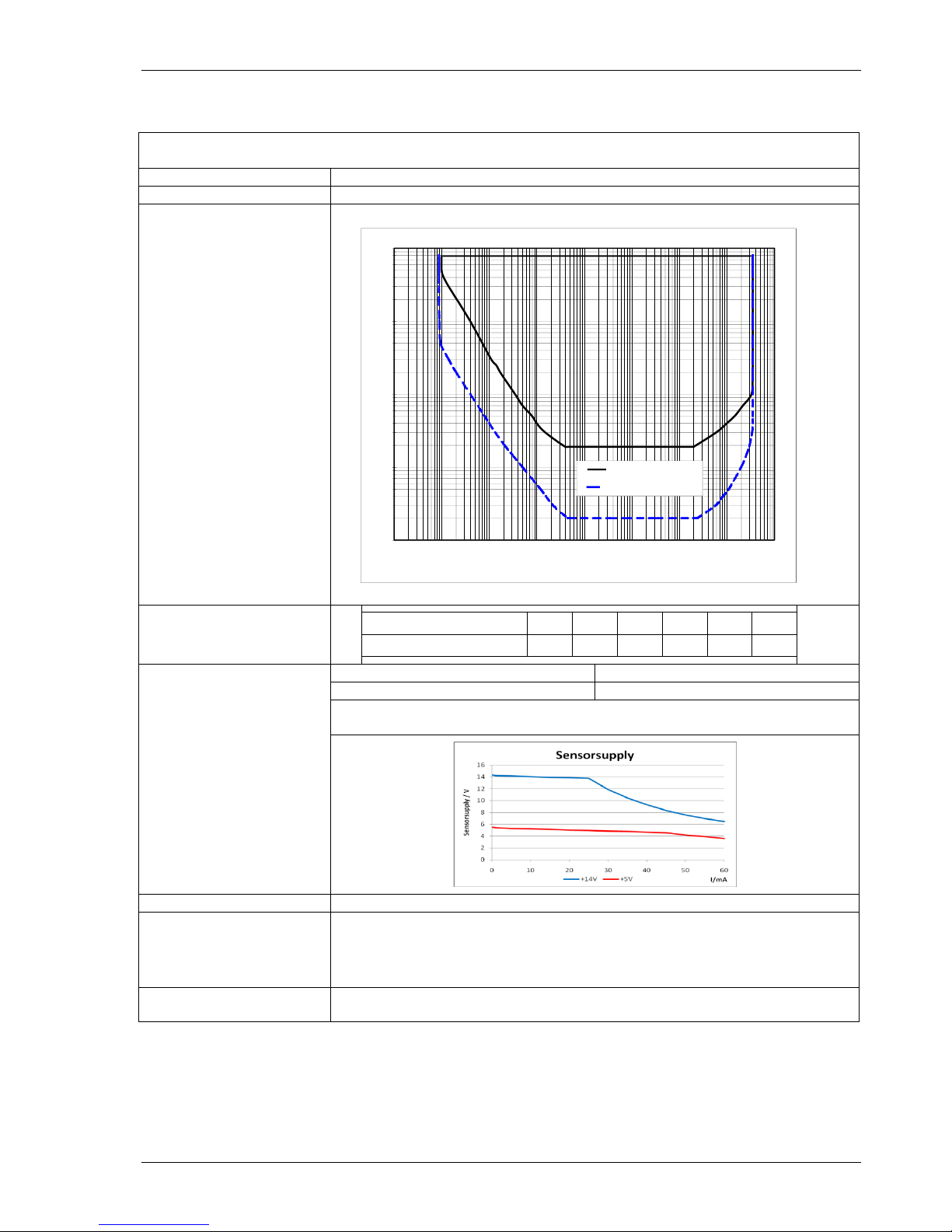
Max. frequency against input voltage
0.01
0.1
1
10
100
0.001
0.01
0.1
1
10
100
1000
10000
100000
Frequency [Hz]
Input voltage [Veff]
Trigger: 500mVpp
Trigger: 20mVeff
O.K.
NOT O.K.
3.2 Inputs
3.2.1 Analog Sensor connection (Sign)
Frequency range (-3dB)
0.01 Hz / 35 kHz
Input impedance
30 kOhm
Input voltage
• Max. 80V
rms
Minimum positive pulse
width - digital signals Input
voltage
Signal voltage [Vpp]
0.5 1 2.5 5 10
20
Min. pulse width [µs]
2000
667
333
200
166
125
Sensor supply
T41x.00
T41x.03
+14V, max. 35mA short circuit proof
+5V, max. 35mA short circuit proof
In case the current limit is activated, the sensor supply must be disconnected to
reset the protection.
Integrated pull-up
820 Ohm to sensor supply (with Jumper J1)
Trigger level
adaptive Trigger level.
Configurable with Jumper J2:
• 250mV … 6.5V (>500mVpp) [Factory configuration]
• 28mV … 6.5V (>20mV
rms
)
Screen
A terminal is provided for the sensor cable screen. This terminal is connected to
the sensor supply 0V. (0VS)
Operating Instructions T411 / T412 JAQUET AG
Revision: 003 7/27
Sensor monitoring
1 of 3 settings may be configured via software:
• No Sensor Monitoring
• Monitoring of powered sensors
[Also for 2 wire sensors supplied via the Pull-up resistor (Jumper J1) ].
The sensor is considered to be defective if the sensor current
consumption falls outside of I
min
and I
max
.
I
min.
= 0.5…25 mA
I
max.
= 0.5…25 mA
• Monitoring of non powered sensors
[For 2 wire sensors such as electromagnetic sensors.]
The sensor is considered to be defective if the circuit is disconnected.
3.2.2 Digital Sensor connection (IQ)
Frequency range (-3dB)
0.01 Hz / 35 kHz
Input impedance
46 kOhm
Input voltage
Max. ± 36V peek
Minimum pulse width
Min. pulse width 1.5 µs
Sensor supply
T41x.00
T41x.03
+14V, max. 35mA short circuit proof
+5V, max. 35mA short circuit proof
In case the current limit is activated, the sensor supply must be disconnected to
reset the protection.
Trigger level
• min.U
low
= 1.6 V
• max.U
high
= 4.5 V
Screen
A terminal is provided for the sensor cable screen. This terminal is connected to
the sensor supply 0V. (0VS)
Sensor monitoring
1 of 2 settings may be configured via software:
• No Sensor Monitoring
• Monitoring of powered sensors
[Also for 2 wire sensors supplied via the Pull-up resistor (Jumper J1) ].
The sensor is considered to be defective if the sensor current
consumption falls outside of I
min
and I
max
.
I
min.
= 0.5…25mA
I
max.
= 0.5…25mA
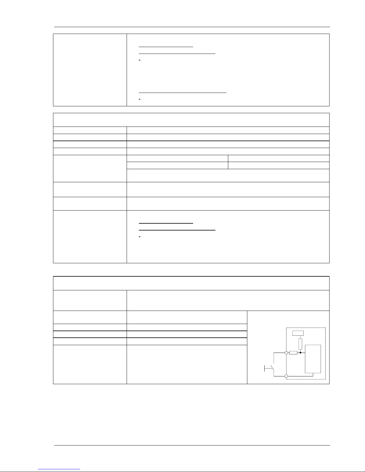
3.2.3 Binary input
Use
For external selection of Parameter set A or B.
• Logic 1 = Parameter set A (Relay control A)
• Logic 0 = Parameter set B (Relay control B)
Levels
Logic 1 = V > +3.5V
Logic 0 = V < +1.5V
Reference
Sensor supply 0V
Max voltage
36V
Input resistance
R
min
= 10k
Circuit
Internal pull up resistance to 5V
Shorting the binary input to the sensor 0V
creates logic 0.
5 volts
T411 / T412
parameter set A B
analysis
+Bin
OVS

Operating Instructions T411 / T412 JAQUET AG
Revision: 003 8/27
3.3 Outputs
3.3.1 Analog output
T411
T412
Type
Current
0…20 / 4…20 mA
Voltage
0…10 / 2…10 V
Load
Max. 500 Ohm
Min. 7 kOhm, Max. 1.4mA
Open circuit voltage
Max. 13V
-
Operating mode
21
20
12
4
0
modus
speed
[rpm]
0...20mA / 0...10V mode
4...20mA / 2...10V mode
initial value
final value
(minimal measured
value)
[mA]
[V]
10.5
10
6
2
0
Transfer functions
Normal or Inverse (rising or falling characteristic)
speed
output
„normal“
speed
output
„invers“
Resolution
12 Bit (4096 steps)
Max Linear error
0.1 %
Accuracy
0.5 % of the full range value.
Signal to Noise Ratio
38.13dB (at 20 mA / 500 Ohm)
Damping
Hardware 11 ms + Software setting (Configuration)
Temperature Drift
Typically 100 ppm/K, max. 300 ppm/K
Reaction time
Effective measuring time + 7.5ms

Operating Instructions T411 / T412 JAQUET AG
Revision: 003 9/27
3.3.2 Relay
Type
Mono-stable change-over
Limit Hysteresis
Programmable – 1 lower and 1 upper set point per limit.
Functions
2 programmable parameter sets selectable via binary input
• Reaction to Alarm, Sensor fault, Limit, always on or off.
• „Normal“ or „Inverse“ (normally powered off or on)
• With or without ‘Hold function’ (Reset via Binary input)
Accuracy
0.05% of the value set
Temperature tolerance
Max. 10 ppm of the value set
Reaction time
Effective measurement time + 10.5ms
Contact rating
AC: max. 250VAC, 1250VA.
DC:
Contact isolation
1500 VAC
3.3.3 Open Collector Output
Type
Opto-coupler (passive)
Activation
Signal from the analogue sensor input (Sign.)
External Pull-up
So far: R = 143 x V (Ic nominal = 7 mA)
After batch 1608: R = 91 x V (Ic nominal = 11 mA)
Load voltage
V = 5 – 30 V
Max load current
25 mA
Isolation
1500 VAC
3.4 Data communication
3.4.1 Serial interface (RS 232)
Physical Layer
Similar to EIA RS 232 but with +5V CMOS Level
Max cable length
2 m
Transmission rate
2400 Baud
Connection
Front panel, 3.5mm jack plug

Operating Instructions T411 / T412 JAQUET AG
Revision: 003 10/27
3.5 Environment
3.5.1 Climatic conditions
Standard
KUE in accordance with DIN 40 040
Operating temperature
- 20 ... + 70 °C
Storage temperature
- 20 ... + 70 °C
Relative humidity
75% averaged over the year; up to 90% for max 30 days.
Condensation to be avoided.
CSA conditions
• Pollution degree 2
• Installation category II
• Altitude up to 1200m
• The T400 system must be installed in an indoor environment
3.5.2 Electromagnetic immunity
Radiation
In accordance with international standards and EN 50081-2
Conducted Emissions
CISPR 16-1, 16-2;
Radiated Emissions
EN 55011
Immunity
In accordance with international standards and EN 50082-2
Electrostatic discharge
IEC 61000-4-2
Contact 6kV, Air 8kV
Electromagnetic Fields
IEC 61000-4-3
30V/m,
non modulated and AM 80% at 1000Hz Sine wave
Conducted fast transients
IEC 61000-4-4
2 kV, repetition rate 5kHz duration 15 ms, period 300 ms
Conducted slow transients
IEC 61000-4-5
Line / Line +/- 1 kV, Earth line +/- 2kV, 1 per Minute
Conducted high frequency
IEC 61000-4-6
3 Vrms (130 dBuV) 10 kHz – 80 MHz,
AM 80% 1000 Hz Sine wave, power cable
Pulse modulation El. - Field
ENV 50140
900MHz (100% pulse mod. /200Hz), > 10 V/m
Power freq. magnetic field
IEC 61000-4-8
50Hz, 100 A/m, 2 Minutes
3.5.3 Other Standards
EN 50155
Railway applications – Electrical Installations on Railway Vehicles
GL
German Lloyd for shipping
UL
Underwriters Laboratories (on request)
CSA ordinary location
• CAN/CSA-C22.2 No. 61010-1-04: Safety Requirements for Electrical
Equipment for Measurement, Control, and Laboratory Use – Part 1:
General Requirements
• UL Std. No. 61010-1 (2nd Edition): Safety Requirements for Electrical
Equipment for Measurement, Control, and Laboratory Use – Part 1:
General Requirements

Operating Instructions T411 / T412 JAQUET AG
Revision: 003 11/27
4 Principle of operation
4.1 General
T400 tachometers are controlled by a microprocessor. They work according to the period measurement
principle whereby the input period is measured with subsequent computing of the reciprocal value
corresponding to the frequency or speed. The relationship between frequency and speed is established with
the Machine factor.
The analogue output (current or voltage) and relay control are determined from the speed.
The relay function is defined via 2 selectable parameter sets. Each parameter set can access the 2 limit
values, the alarm definition, sensor monitoring and other process values.
Both limits have an upper and lower set point (hysteresis setting)
The selection of the valid parameter set is done via the binary input.
The relay status may be held until reset via the binary input
The system continuously monitors itself. In addition the sensor may be monitored. Dependent upon the
configuration, these conditions can influence the relay and analogue output.
The alarm status is indicated via the front panel LED
The frequency output (open collector output) is not influenced by the machine factor and corresponds to the
input signal frequency. The IQ input is not connected to the frequency output.
The input of all parameters is done via PC software and the RS232 interface. This may also be used to
interrogate the unit’s settings, measurement and general status.
Parameters are retained in an EEPROM.
Sensor supply
Sensor control
Periodic time
measurement
Frequency
calculation
Machine
factor
X
Definition limit 1
Definition limit 2
Definition current output
Definition
Relay
Analysis of the
binary input
Reset
Choice of the parameter set A/B
Sensor failure
Frequency
Speed
System failure
System control
Definition Alarm
LED
Relay
Current
output
Open
Collector
IQ-
Sensor
binary
input
RS 232
EEPROM
Display
Sensor
connection
(Sign.)

Operating Instructions T411 / T412 JAQUET AG
Revision: 003 12/27
4.2 Machine factor
The machine factor establishes the relationship between sensor frequency and corresponding speed.
There are 2 ways of determining the value:
4.2.1 Known (Measured)
4.2.2 Calculated
The relationship between a sensor signal frequency (f) and speed (n) of a pole wheel is:
From which the formula for machine factor is:
If there is a gearbox between the pole wheel and the shaft speed to be measured:
Whereby the gearbox ratio is:
4.2.3 Displaying other physical values
In principle any physical value that can be measured proportional to speed may be displayed.
The formula above should then be modified accordingly.
f = Signal frequency in Hz
n = Pole wheel speed in rpm
p = Nr. of teeth
60
pn
f
60
ip
M
M = Machine factor
p = Nr. of pole wheel teeth
i = Gearbox ratio
1
2
2
1
p
p
n
n
i
i = Gearbox ratio
n1 = Pole wheel speed (Sensor position) primary side
n2 = Pole wheel speed (Speed to be displayed) secondary side
p1 = Nr. of teeth primary side
p2 = Nr. of teeth secondary side
n
f
M
M = Machine factor
f = Signal frequency at machine speed n
n = Machine speed
60
p
M
M = Machine factor
p = Nr. of teeth
n
f
M
M = Machine factor
f = Signal frequency at known machine speed
n = Machine speed at measured signal frequency

Operating Instructions T411 / T412 JAQUET AG
Revision: 003 13/27
5 Installation
T400’s may only be installed by trained and competent personnel. An undamaged T400, valid configuration
and suitable installation are required. Please refer to the Safety Instructions in Section 1.
In the case of an emergency, it should be possible to disconnect the T400 from mains using a switch or
similar means. These instruments correspond to protection class I and earthing of the PE terminal is therefore
mandatory.
Before switching the equipment on, it is mandatory to verify that the power supply voltage is in the permissible
range.
The sensor cable screen must be connected to the terminal ‘Sh’ so as to minimize the influence of noise. This
terminal is directly connected internally to 0VS.
CSA requirement: PERMANENTLY CONNECTED EQUIPMENT requires the special considerations to satisfy
the CEC and the Canadian deviations in the standard, including overcurrent and fault protection as required.
6 Connnections
6.1 Front view
The T411 / T412 display along with the RS232 interface and the status LED are located at the front.
Communications via RS232 are described in section 8.2.

Operating Instructions T411 / T412 JAQUET AG
Revision: 003 14/27
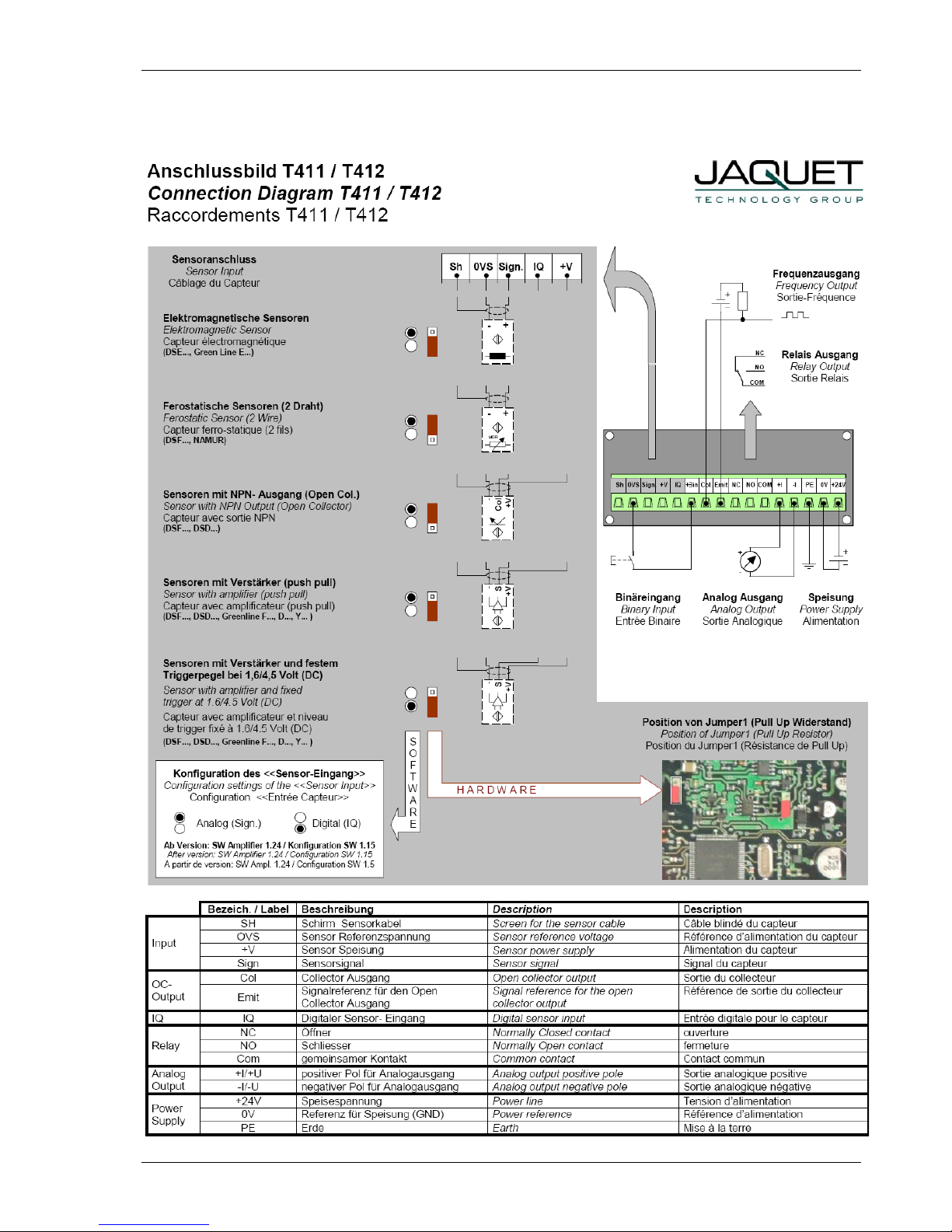
6.2 T411 terminals
T411
Sh
0VS
Sign
+V
IQ
+Bin
Col
Emit
NC
NO
COM
+I
-I
PE
0V
+24V
Sensor connections
SH : Screen – Sensor cable
0VS : Sensor Reference voltage
+V : Sensor Supply
Sign : Sensor signal analog
IQ : Sensor signal digital
Binary Input
+Bin : Connection of a switch (to 0VS)
Open Collector output
Col : Collector output
Emit : Signal reference for the Open
Collector
Relay output
NC : Normally closed
NO : Normally open
Com : Common
Analog output
+ I : Current positive
- I : Current negative
Supply
+24V : Power (10 ... 36 V)
0V : Power reference
PE : Earth
6.3 T412 Terminals
T412
Sh
0VS
Sign
+V
IQ
+Bin
Col
Emit
NC
NO
COM
+U
-U
PE
0V
+24V
Sensor connections
SH : Screen - Sensor cable
0VS : Sensor Reference voltage
+V : Sensor Supply
Sign : Sensor signal analog
IQ : Sensor signal digital
Binary Input
+Bin : Connection of a switch (to 0VS)
Open Collector output
Col : Collector output
Emit : Signal reference for the Open
Collector
Relay output
NC : Normally closed
NO : Normally open
Com : Common
Analog output
+ U : Voltage positive
-U : Voltage negative
Supply
+24V : Power (10 ... 36 V)
0V : Power reference
PE : Earth
Operating Instructions T411 / T412 JAQUET AG
Revision: 003 15/27
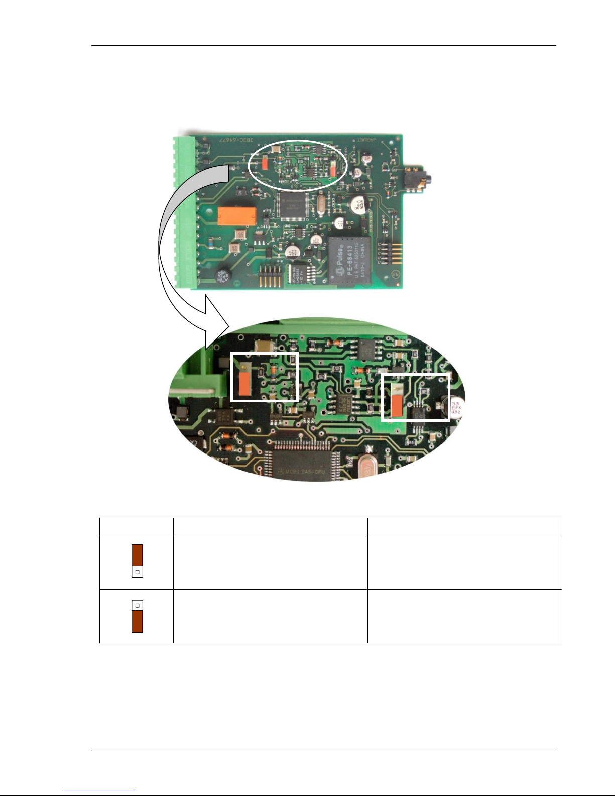
7 Hardware configuration
7.1 Analog Sensor input (Sign)
Jumper position
J1: Sensor type
J2: Adaptive trigger level range
2 wire sensors
(with 820Ohm Pull Up resistance)
28mV to 6.5V (>20mV
rms
)
3 wire and electromagnetic sensors
(factory setting)
250mV to 6.5V (>500mVpp)
[factory setting]
7.2 Digital Sensor input (IQ)
No hardware configuration possible or necessary.
J2
J1
Operating Instructions T411 / T412 JAQUET AG
Revision: 003 16/27
8 Configuration with PC Software
8.1 Software concept
All settings are written via PC to the T400 using the RS232 interface and the user friendly menu driven T400
software.
The parameter file may be stored, opened, printed and exchanged between the T400 and a PC.
8.2 PC communications
Communications with the T400 are initiated by the PC via the RS232 interface.
Before starting the first connection, Settings Interface must be set to an appropriate serial interface.
The following settings also apply:
Transmission rate: 2400 Baud
Parity Bit: none
Data Bits: 8
Stop Bits: 2
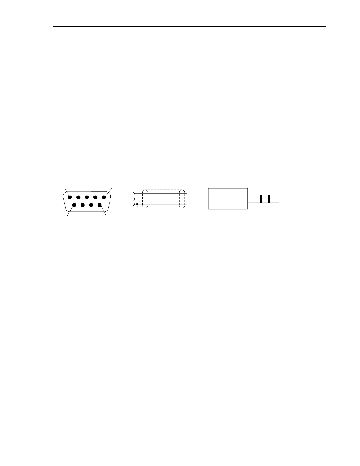
Connector: 3.5mm jack plug
235
TXD
RXD
GND
TXD
RXD
GND
5
1
9
6
female
The diagram shows the stereo jack plug to D9 connections.
The tachometer RXD must be connected to the PC’s TXD and vice versa.
T411 / T412’s do not use a standard RS232 signal (-5V…+5V) but operate at 5V CMOS levels, compatible
with most PC’s as long as the cable is not longer than 2m.
A suitable cable may be ordered from JAQUET AG – see section 11.
8.3 PC Software settings
8.3.1 Interface (Settings Interface)
In this menu the serial interface for communication with the T400 is defined.
8.3.2 Display Interval (Settings Display Interval)
The T400 measurement status may be interrogated and displayed on the PC via T400 Start – Reading
Measure Data.
The display update time may be set at intervals of ¼ to 10 seconds.

Operating Instructions T411 / T412 JAQUET AG
Revision: 003 17/27
8.4 Parameter list and ranges
If you already have a configuration file you can open and view it using the T400 Windows Software menu
File Open
You can also connect the T400 to a PC (see section 8.2) and read back the parameters,
T400 Read parameters
Once loaded into the software the parameter set may be printed via File Print
Normal Windows file handling rules apply.
Parameter list and ranges. Factory settings are shown in bold.
Instrument Type
Manufacturer’s code
Software version
Calibration date
Configuration < System >
Machine factor
1.0000E-07 ... 1.0000 ... 9.9999E+07
Minimum Measuring time
2 / 5 / 10 / 20 / 50/ 100 / 200 / 500 ms / 1/ 2 / 5 Seconds
Min displayed measured value
1.0000E-12 ... 1 ... 1.0000E+12
Alarm definition
Only System error / System error OR Sensor Monitoring
Configuration < Sensor >
Sensor Type
Active / Passive
Sensor input
Analog (Sign) / Digital (IQ)
Sensor current minimum
0.5 ... 1.5 ... 25.0mA
Sensor current maximum
0.5 ... 25.0mA
Configuration < Analog output >
Measuring range start value
0.0000 ... 90% of the end value
Measuring range end value
1Hz … 2000.0 … 500000
Output range
0 ... 20mA / 4 ... 20mA (T411)
0 ... 10V / 2 ... 10V. (T412)
Time constant (Damping)
0.0 ... 9.9s
Configuration < Limits >
Status Limit 1
On / Off
Status Limit 2
On / Off
Mode Limit 1
Normal / Inverse
Mode Limit 2
Normal / Inverse
Lower Set point Limit 1
0.1 … 200.00 … 500000
Upper Set point Limit 1
0.1 … 300.00 … 500000
Lower Set point Limit 2
0.1 … 400.00 … 500000
Upper Set point Limit 2
0.1 … 500.00 … 500000
Configuration < Relay control >
Switching of control A/B
Selection of actuator
None (always control A) / Binary Input B1
Delay time
0 ... 2’000 s
Relay Assignment
Control A
Alarm / Sensor monitor / Limit 1 / Limit 2 / Window / On / Off
Acknowledge A
Without acknowledge (no hold function) /
Relay held when control active /
Relay held when control inactive
Acknowledge B
Alarm / Sensor monitor / Limit 1 / Limit 2 / Window / On / Off
Acknowledge B
Without acknowledge (no hold function) /
Relay held when control active /
Relay held when control inactive
Operating Instructions T411 / T412 JAQUET AG
Revision: 003 18/27
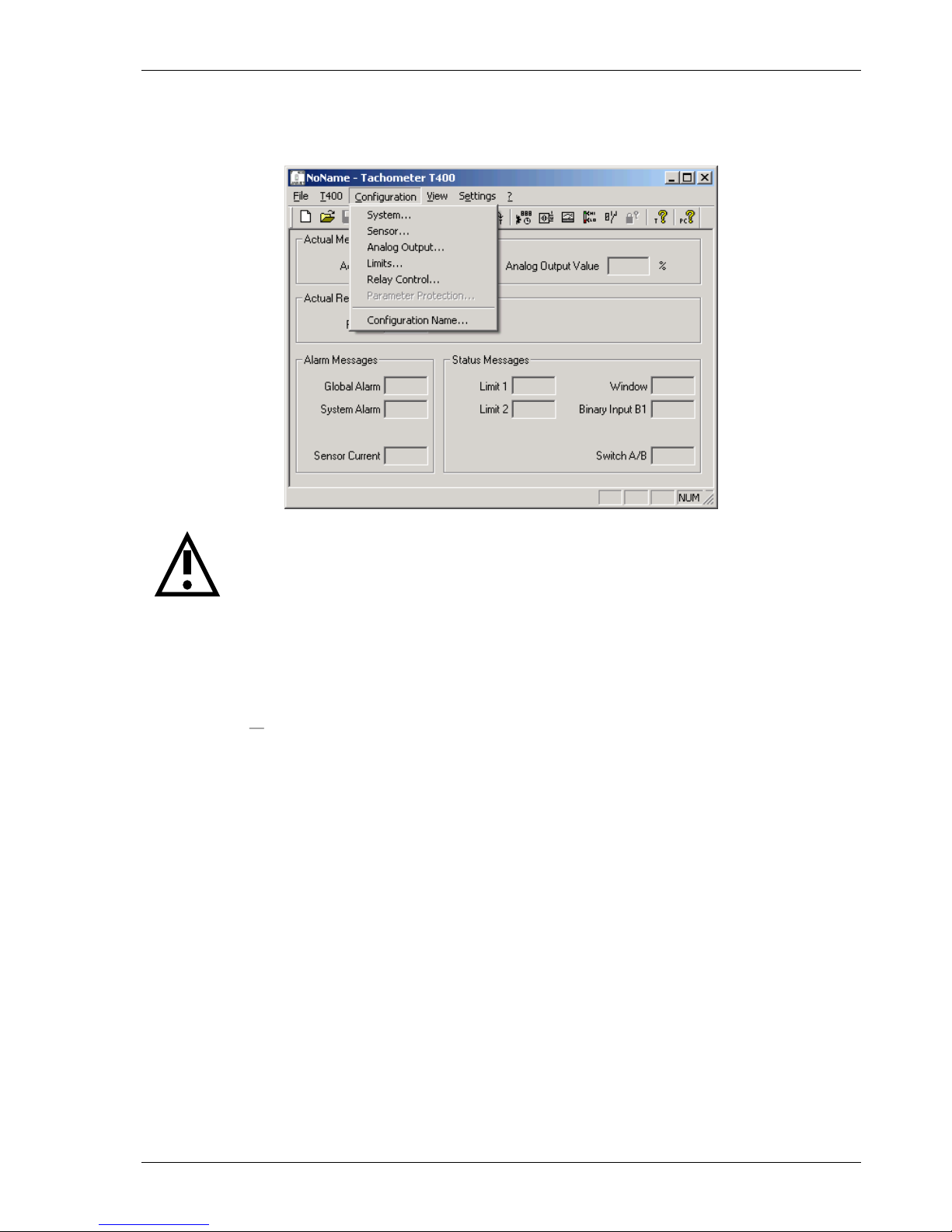
8.5 Parameters
Parameters are changed in the sub menus from the drop down menu „Configuration“.
Warning:
New configurations only become active after being uploaded into the T400 via:
T400 Write Parameters
8.5.1 System parameters (Configuration System)
Machine factor
The machine factor establishes the relationship between sensor frequency and associated speed.
See section 4.2 Machine factor.
Once the correct machine factor is entered, all other settings e.g limits are made in rpm.
Minimum Measuring Time
The minimum measuring time determines the time during which the input frequency is measured. The
calculation is made after termination of this time and after reaching the end of the current signal period. The
minimum measuring time may be increased to filter out frequency jitter so as to display a stable reading but at
the cost of increased reaction time.
Minimum displayed value
The minimum displayed value is a measured value under which „0000“ is displayed.
Alarm definition
This function defines the alarm. It may be only system error or a logical OR combination of system error OR
sensor monitoring. During an alarm the LED is off. In addition, the relay is deactivated and the analog output
goes to 0mA (0V) irrespective of the output range.
n
f
M
M = Machine factor
f = Signal frequency at machine speed n
n = Machine speed

Operating Instructions T411 / T412 JAQUET AG
Revision: 003 19/27
8.5.2 Sensor parameter (Configuration Sensor)
Sensor Type
The type of sensor to be used is defined here.
<Sensor active> is for monitoring sensors powered by T400 including 2 wire sensors supplied via the internal
pull up resistor. (Jumper J1).
<Sensor passive> is for monitoring non powered sensors e.g. 2 wire VR sensors.
See also section 9.4.1 Sensor fault (Sensor monitoring).
Sensor input
The sensor input “analog” (Sign) or “digital” (IQ) is defined here.
Sensor current minimum
As long as the sensor current consumption lies above the value <Current Minimum>, the sensor is considered
to be functioning correctly.
Sensor current maximum
As long as the sensor current consumption lies below the value <Current Maximum>, the sensor is considered
to be functioning correctly.
8.5.3 Analog Output (Configuration Analog Output)
21
20
12
4
0
modus
speed
[rpm]
0...20mA / 0...10V mode
4...20mA / 2...10V mode
initial value
final value
(minimal measured
value)
[mA]
[V]
10.5
10
6
2
0
T412
T411
Measuring range – start value
Analog output start value 0/4mA or 0/2V
Measuring range – end value
Analog output end value 20mA or 10V
In the case of a negative transfer function the end value must be set smaller than the start value.
Output range
0…20mA or 4…20mA for the T411. 0…10V or 2…10V for the T412.
Output time constant
The analog output signal may be smoothed by applying a software time constant. This damping is deactivated
when the time constant is 0.0 seconds.
Operating Instructions T411 / T412 JAQUET AG
Revision: 003 20/27
8.5.4 Limit (Configuration Limit)
The T400 series offers 2 independent limits Limit 1 and 2.
Status
Limits are selected here. If the limit is deactivated, the other values such as set points and mode have no
further effect.
Mode
In Normal Mode the limit is active as soon as the High set point is exceeded. In Inverse Mode the limit is active
from the start (zero speed) and deactivates when the set point is reached (Fail Safe operation)
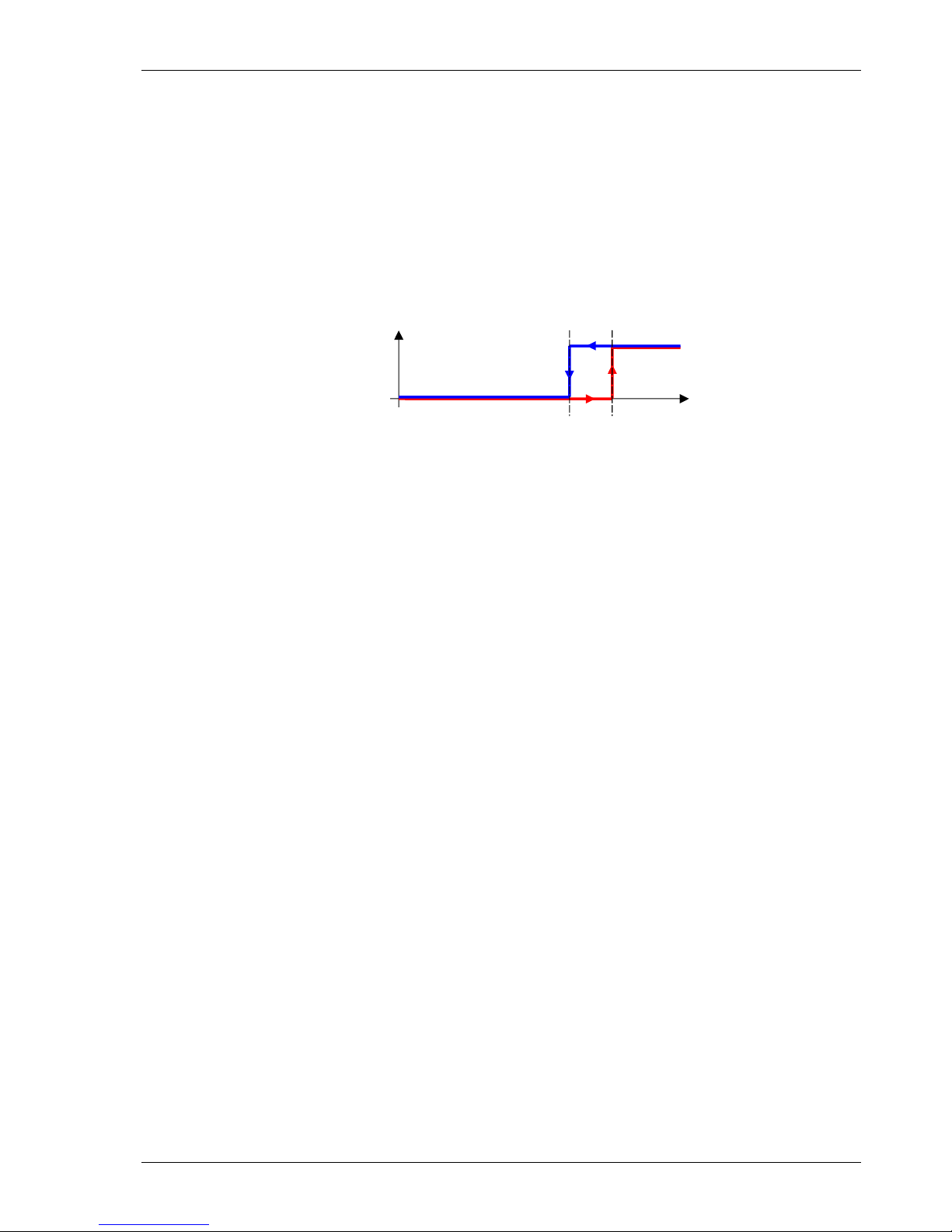
Upper and Lower Set point
rpm
limit
activated
deactivated
lower
switching point
upper
switching point
As the speed increases, the limit switches when the High set point is reached and remains in that condition
until the speed reduces past the Low set point.
8.5.5 Relay parameter and selection of Parameter set
(Configuration Relay control)
Parameter set A / B selection
The parameter set B may be activated via the binary input <Binary input B1>.
If parameter set B is to be deactivated, this setting should be none (always control A)
Delay time when switching B -> A
This value corresponds to the time needed for switching from parameter set B to parameter set A after
changing the binary input accordingly.
Relay assignment with control A
Defines the relay behavior in parameter set A.
Relay assignment with control B
Defines the relay behavior in parameter set B.
Relay
Defines the source information for relay switching.
Status register
Relay dependency
• Alarm
(Common) Alarm (8.5.1 System parameters (Configuration System))
• Sensormonitor
Sensor status (8.5.2 Sensor parameter (Configuration Sensor))
• Limit 1/2
Selection of Limit 1/2 (8.5.4 Limit (Configuration Limit))
• Window
ExOR combination of both limits Offserhalb des Fensters ab, definiert über die Limits 1 and 2
• On
The relay is on
• Off
The relay is always off
Acknowledge
Acknowledge establishes if and under what conditions the relay status is held. A relay that is held no longer
reacts to the assigned signal and can only be reset via the binary input.
Operating Instructions T411 / T412 JAQUET AG
Revision: 003 21/27
9 Operating behavior
9.1 Power on
9.1.1 Analogue Output
After switching-on the tachometer, the output relates the lower value of the defined output range. After
completion of the first measurement the output goes to the corresponding measured value.
9.1.2 Relay Output
The parameter set determined by the configuration and binary input is valid from the start.
If the relay is assigned to a limit it remains deactivated until completion of the first measurement. After this it
switches to the status, which is defined under <Limit>.
If the relay is assigned to any other item in the status register it immediately switches to the corresponding
status.
If no input frequency is present, then after a period of 2 x Fixtime a measured value below the lower set point
is assumed.
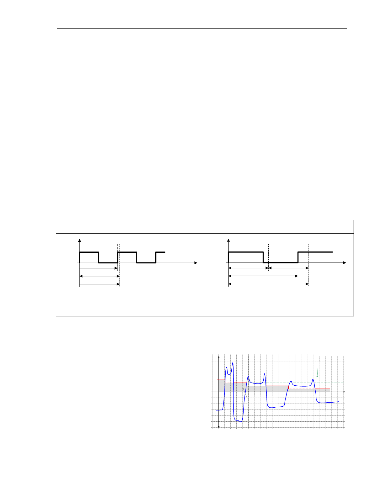
9.2 Measurement
Every measurement begins with the positive edge of the input signal. The next positive edge closes the
current measurement and starts the next one after termination of the fixtime.
The resulting effective measurement time is dependent upon whether the input signal period is longer or
shorter than the Fixtime.
Input signal period < Fixtime
Input signal period > Fixtime
Input
Frequency
End of Fixtime
Ensuing edge
Fixtime
Input period
time
Effective measurement period
t
Messung typisch
= Fixtime
t
Messung maximal
= 2 x Fixtime
Input
Frequency
End of Fixtime
Ensuing edge
Period of input signal
Fixtime
time
Fixtime
Effective measurement period
t
Messung maximal
= 2 x Input signal period
The total measurement time has a resolution of 0.4 s.
The calculation and adaptation of outputs follows immediately after the Fixtime.
With input frequencies outside of the measuring range, the corresponding final values will be assumed.
9.2.1 The adaptive Trigger level
After triggering, the trigger level is set for the next pulse
anew.
This guarantees that the trigger level can follow a 50%
reduction in speed from pulse to pulse.
DC offset, resonance and negative pulses have no
influence on the triggering
t
trigger level
signal to
noise ration
bad sensor
signal
U
old trigger level

Operating Instructions T411 / T412 JAQUET AG
Revision: 003 22/27
9.2.2 Signal failure
In the event of a sudden loss of a good signal, no positive edge arrives to complete the measurement
or start a new one. Once the minimum measurement time (Fixtime) has lapsed, the unit waits for twice the last
measurement period, following which half the last measured speed is assumed.
If the signal remains missing then the measurement approaches zero following an e-function.
9.3 Functions
9.3.1 Limits and Window Function
Since the upper and lower sets points are freely selectable a large hysteresis may be set. If that is not
necessary we recommend setting a 10% hysteresis.
The Window function allows an Exclusive OR combination of Limits 1 and 2, whereby the status of both limits
is first determined (including any inversion) and a subsequent ExOR comparison executed.
As soon as Relay assignment is <Window> the relay behaves as follows:
• With identical limit modes (both Normal or both Inverse) the relay is activated when the measured value
lies between the Limit 1 and 2 settings.
• If different modes are set (one Normal and the other Inverse) the relay is deactivated when the measured
value is between Limits 1 and 2.
9.3.2 Parameter set A and B
T400’s have 2 parameter sets available that define the relay assignment. Parameter set A would normally be
used. If another parameter set is needed, e.g. for test purposes, the binary input may be used to change to
parameter set B. The transfer from parameter set B to parameter set A may be delayed in the range 0 to 2000
seconds. Transferring from A to B is however immediate and not affected by this setting.
To be able to select parameter sets using the binary input, Relay control - Selection of Actuator must be
appropriately set, see 8.5.5.
Binary input condition
Selected Parameter set
High (5V) „normal“
A
Low (0V) „connected to 0V“
B
9.3.3 Relay hold function
A latch function may be assigned to the relay. By selecting <Relay is hold if control is active> the relay is
activated once the assigned limit is active and remains held even if the input frequency would no longer cause
a trip. By selecting <Relay is hold if control is inactive>, the deactivated state of the relay is held. The latched
status may be reset by cycling power or via the binary input, whereby the binary input must be activated as per
the configuration (0V or 5V) for between 0.1 and 0.3 seconds.

Operating Instructions T411 / T412 JAQUET AG
Revision: 003 23/27
9.3.4 Binary Input
2 functions are executable using the binary input:
• Switching between parameter sets A and B. See 9.3.2 Parameter set A and B.
• Resetting a latched relay. See 9.3.3 Relay hold function.
The binary input has an internal pull up resistor to +5V and is therefore normally logic High.
Shorting the binary input to the sensor supply 0V creates a logic 0.
Switching the input for between 0.1 and 0.3 seconds resets a latched
relay but does not influence parameter set selection, which requires
longer than 0.3 seconds.
9.4 Fault behavior
9.4.1 Sensor fault (Sensor monitoring)
The sensor may be monitored in 2 ways. With sensors powered by the T400 the sensor supply current is
monitored. If the current falls outside the permitted range then sensor fault is indicated.
If the sensor is not powered by the T400 then it may only be monitored for disconnection. If disconnected,
sensor fault is indicated.
The T400 behavior in the event of a sensor fault is depending on the configuration:
Alarm Configuration
Outputs in the event of a sensor fault
LED
Analog output
Relay
Current (T411)
Voltage (T412)
Only System error
On
Measured value output per configuration
System error OR Sensor monitoring
Off
0mA
0V
deactivated
9.4.2 System alarm
If the microprocessor detects a checksum fault (RAM, ROM or EEPROM) the measured value is set to 0rpm,
the analog output goes to 0 mA or 0 V and the relay is deactivated.
Alarm Configuration
Outputs in the event of a System alarm
LED
Analog output
Relay
Current (T411)
Voltage (T412)
Only System error
Off
0mA
0V
deactivated
System error OR Sensor monitoring
9.4.3 Alarm
As long as a combined alarm is present, no measurements are conducted and the outputs behave as
described above. Once the fault or alarm condition is removed the last correct measured value is assumed.
Eventual limit activation is not taken into account.
9.5 Power supply interruption
If the PSU remains off for longer than the permitted period the outputs deactivate i.e. the analog output goes
to 0mA (0V), the relay deactivates and the „open collector“ output becomes high resistance.
Once the supply resumes in range the T400 begins its initialization routine (see chapter 9.1)
5 Volt
T411 / T412
parameter set A B
analysis
+Bin
OVS
10k

Operating Instructions T411 / T412 JAQUET AG
Revision: 003 24/27
9.6 Display adjustments
9.6.1 Brightness
The brightness of the display can be adjusted by pressing the up and down arrow buttons at the front panel.
9.6.2 Contrast
The contrast of the display can be adjusted by pressing the up or down arrow button and the center button at
the front panel.
10 Mechanical Construction / Housing
Housing Material
Noryl SE GFN1, black RAL 9005
Mounting
Using DIN 43835 Form B clamps
Terminals
Detachable Terminal block.
2.5 mm 2 - Cable or 1.5 mm2 flex
AWG 24 – AWG 12
UL CSA
Sealing to EN 60925
resp. IEC 925
Housing IP 40
Terminals IP 20
Dimensions
Labeling
Isopropanol-resistant type label.

Operating Instructions T411 / T412 JAQUET AG
Revision: 003 25/27
11 Accessories
Interface cable RS232 PC – T400 Part Nr. 830A-36889
Cable for PC to tachometer communications.
USB adapter for interface cable Part Nr. 830A-37598
USB to RS232 converter.
Power supply 100-240Vac/24Vdc, 1A Part Nr. 383Z-05764
12 Maintenance / Repair
T400 tachometers do not require maintenance since they exhibit minimal drift and do not use batteries or other
consumables. If the instrument is to be cleaned please note the protection class. It is preferable to remove all
forms of power (including relay contact supply) during cleaning. Surface cleaning may be carried out using
spirit, pure alcohol or soap only.
13 Software Versions
• Since unit software version 1.24 or higher and configuration software 1.15 or higher the digital sensor
(IQ) input is available. Additionally the value range of the measured speed has been increased to
500k.
• For software display version 1.2 are values to 999.9k possible.
14 Warranty
The standard warranty in the event of a manufacturing failure confirmed by Jaquet consists of repair or
replacement within 12 months of delivery. Ancillary costs are excluded s well as damages caused by use
outside of the specification. Complaints concerning visible defects will only be accepted if advised to Jaquet
within 14 days of receipt.

Operating Instructions T411 / T412 JAQUET AG
Revision: 003 26/27
15 Declaration of conformity
Operating Instructions T411 / T412 JAQUET AG
Revision: 003 27/27
16 Connection diagram T411/412
 Loading...