


JAQUET AG, Thannerstrasse 15, CH-4009 Basel
Tel. +41 61 306 88 22 Fax +41 61 306 88 18
FT 3000 Speed measurement system
3-channel speed control and overspeed protection
System documentation FT 3000 :
• Operating instructions FT 3000
• Operating instructions sensor
• Rack 19 ¨ description
• Bloc function description
• System configuration
• Connection diagram
• IEC 61508 certificate

Operating Instructions FT 3000JAQUET AG
377E-63917 Rev 4.00 page 2 of 47
Table of contents
1 THE REDUNDANT OVER SPEED PROTECTION CONCEPT :.............................................................. 5
2 SAFETY WARNING..................................................................................................................................... 7
3 APPLICATIONS............................................................................................................................................ 7
4 CONSTRUCTION......................................................................................................................................... 7
5 FRONT PANEL DESCRIPTION....................................................................................................... ...........8
5.1 FTFU 3024............................................................................................................................................. 8
5.2 FTV 3090 ............................................................................................................................................... 8
5.3 FTK 3072...............................................................................................................................................9
5.4 FTW 3013............................................................................................................................................... 9
5.5 FTBU 3034 .......................................................................................................................................... 10
6 SPECIFICATIONS...................................................................................................................................... 11
6.1 S
TATISTICS............................................................................................................................................ 11
6.2 IEC 61508-2-3
SPECIFICATIONS :..........................................................................................................11
6.3 T
ECHNICAL DATA OSPS........................................................................................................................ 11
6.4 T
ECHNICAL DATA TCCC........................................................................................................................ 16
7 PRINCIPLE OF OPERATION.................................................................................................................... 16
7.1 M
EASURING SYSTEM.............................................................................................................................. 16
7.2 M
EASURING PRINCIPLE .......................................................................................................................... 16
7.2.1 Standardising the measured value.........................................................................................16
7.2.2 Speed monitor............................................................................................................................ 16
7.2.3 Frequency measurement (Period measurement principle) ................................................ 16
7.2.4 Acceleration measurement......................................................................................................19
7.2.5 Limit value control..................................................................................................................... 21
7.2.6 Limit value time control............................................................................................................ 21
7.3 M
ONITORING FUNCTIONS........................................................................................................................ 21
7.3.1 Supply.......................................................................................................................................... 21
7.3.2 Monitoring of internal voltages................................................................................................ 21
7.3.3 Sensor monitoring..................................................................................................................... 21
7.3.4 System monitoring....................................................................................................................22
7.3.5 Module OK message................................................................................................................. 22
7.3.6 Fault condition ........................................................................................................................... 22
7.4 D
IRECTION OF ROTATION DISCRIMINATOR............................................................................................... 22
7.5 R
ELAY CONTROL.................................................................................................................................... 22
7.6 T
EST FREQUENCY GENERATOR .............................................................................................................. 23
Operating Instructions
377E-63917
V 4.00 20.12.04
FT 3000

Operating Instructions FT 3000JAQUET AG
377E-63917 Rev 4.00 page 3 of 47
7.7 TEST...................................................................................................................................................... 23
7.8 F
REQUENCY OUTPUTS ........................................................................................................................... 23
7.9 L
AMP TEST.............................................................................................................................................24
7.10 M
ESSAGE ACKNOWLEDGEMENT............................................................................................................. 24
7.11 B
INARY INPUTS...................................................................................................................................... 24
7.12 P
ARAMETER ENTRY................................................................................................................................24
7.13 SIGNAL MONITORING.............................................................................................................................. 24
8 INSTALLATION.......................................................................................................................................... 26
8.1 G
ENERAL............................................................................................................................................... 26
8.2 IEC 61508-2-3 S
PECIFIC INSTALLATION RULES.....................................................................................26
9 SETTING PARAMETERS AND OPERATION.........................................................................................27
9.1 S
OFTWARE CONCEPT............................................................................................................................. 27
9.1.1 Process parameter list.............................................................................................................. 27
9.1.2 Configuration parameter list.................................................................................................... 27
9.1.3 Service parameter list............................................................................................................... 29
9.2 PC
COMMUNICATIONS............................................................................................................................ 29
9.2.1 PC system requirements.......................................................................................................... 29
9.2.2 PC software installation............................................................................................................ 29
9.2.3 Optimisation...............................................................................................................................30
9.2.4 Setting the display interval....................................................................................................... 30
9.2.5 Protection of configuration parameters................................................................................. 30
9.2.6 Protection of process parameters .......................................................................................... 30
9.2.7 Reading and writing parameters............................................................................................. 30
9.2.8 Parameter printout..................................................................................................................... 30
9.2.9 Display of current measured data........................................................................................... 30
9.3 S
ETTING PARAMETERS........................................................................................................................... 31
9.3.1 System settings ......................................................................................................................... 31
9.3.2 Sensor monitor .......................................................................................................................... 32
9.3.3 Analog outputs........................................................................................................................... 32
9.3.4 Limit values.................................................................................................................................32
9.3.5 Test values.................................................................................................................................. 33
9.3.6 Parameter enable....................................................................................................................... 33
9.3.7 Password .................................................................................................................................... 33
9.4 O
PERATING BEHAVIOUR......................................................................................................................... 33
9.4.1 Power up.....................................................................................................................................33
9.4.2 Measurements............................................................................................................................ 34
9.4.3 Response to sensor failure...................................................................................................... 34
9.4.4 Behaviour during system alarm..............................................................................................34
9.4.5 Response to mains failure........................................................................................................ 34
9.5 F
REQUENCY MEASUREMENT CALIBRA TION............................................................................................. 34
9.5.1 Calibration tools......................................................................................................................... 35
9.5.2 Factors influencing accuracy .................................................................................................. 35
9.5.3 Calibration rules......................................................................................................................... 35
9.6 C
ALIBRATING THE SENSOR MONITOR...................................................................................................... 36
9.6.1 Factors influencing accuracy .................................................................................................. 36
9.6.2 Calibration rules......................................................................................................................... 36
10 MECHANICAL CONSTRUCTION......................................................................................................... 37
11 CIRCUIT DESCRIPTION........................................................................................................................ 39
11.1 FTFU 3024 M
OTHERBOARD AND INPUT CA RD....................................................................................... 39
11.1.1 Frequency measurement.......................................................................................................... 39
11.1.2 Speed monitors.......................................................................................................................... 39
11.1.3 Micro controller.......................................................................................................................... 39
11.1.4 Supply.......................................................................................................................................... 39
11.1.5 Reset and non-maskable interrupt (NMI)............................................................................... 40
11.1.6 Input amplifier ............................................................................................................................ 40
11.1.7 Sensor monitoring..................................................................................................................... 40
11.1.8 Module monitoring .................................................................................................................... 41
11.1.9 Relay outputs ............................................................................................................................. 41

Operating Instructions FT 3000JAQUET AG
377E-63917 Rev 4.00 page 4 of 47
11.1.10 LIMIT LED’s............................................................................................................................. 41
11.1.11 Frequency generator............................................................................................................. 41
11.1.12 Frequency outputs ................................................................................................................ 41
11.1.13 Binary inputs .......................................................................................................................... 41
11.1.14 Test .......................................................................................................................................... 41
11.1.15 Direction of rotation discriminator...................................................................................... 42
11.1.16 Lamp test ................................................................................................................................42
11.2 FTW 3013 - A/D
CONVERTER AUXILIARY MODULE.................................................................................42
11.2.1 Supply.......................................................................................................................................... 42
11.2.2 Analog outputs........................................................................................................................... 42
11.3 FTV 3090 R
ELAY CARD ........................................................................................................................ 42
11.3.1 Supply.......................................................................................................................................... 42
11.3.2 Relay outputs ............................................................................................................................. 42
11.4 FTK 3072 C
OMMS MODULE .................................................................................................................. 42
11.4.1 Rack bus ..................................................................................................................................... 42
11.4.2 RS 232 interface......................................................................................................................... 43
12 MAINTENANCE...................................................................................................................................... 44
12.1 P
ERIODIC TEST.......................................................................................................................................44
12.1.1 Description ................................................................................................................................. 44
12.1.2 IEC 61508-2-3 specifications.................................................................................................... 44
12.2 T
ROUBLE SHOTING :...............................................................................................................................45
12.2.1 Procedure for the OSPS ........................................................................................................... 45
12.2.2 Procedure for the TCCC :.........................................................................................................46
12.2.3 IEC 61508-2-3 specifications.................................................................................................... 46
12.3 M
ODULE EXCHANGING :......................................................................................................................... 46
12.3.1 General........................................................................................................................................46
12.3.2 IEC 61508-2-3 specifications :.................................................................................................. 47
13 STORAGE...............................................................................................................................................47
14 WARRANTY............................................................................................................................................ 47
15 DRAWINGS............................................................................................................................................. 47

Operating Instructions FT 3000JAQUET AG
377E-63917 Rev 4.00 page 5 of 47
1 The Redundant Over Speed Protection Concept :
Speed
Measurement
1
Speed
Measurement
2
Speed
Measurement
3
PSU 1 PSU 2
2 of 3
Module
commissio
ning
Customer specific control logic, 1/3, 2/3 …
Secure monitoring
even if modules are
exchanged during
operation
1. Measurement
Protection
Safety
Availability
3. Measurement
Protection
Safety
Availability
2. Measurement
Protection
Safety
Availability
OUTPUT CONTACTS
Secure supply via
redundant PSU’s
allowing exchange
during operation
FT 3000


Operating Instructions FT 3000JAQUET AG
377E-63917 Rev 4.00 page 7 of 47
2 Safety Warning
During operation, parts of the FT 3000 are under dangerous voltages. The units conform to protection class 1 and
require an earth connection on the corresponding module connector and/or termi nal on the 19" rack.
The units have been designed and tested in accordance with IEC 348 and have left the factory in perfect condition.
These operating instructions include information and guidance on the safe operation of the equipment and installation.
Please specially note section 6.
If in doubt about the condition of any part following electrical, environmental or mechanical damage, the unit should be
returned for repair.
3 Applications
FT 3000 tachometers are used to monitor and measure frequencies in the range 0 to 30000Hz eg from frequency
proportional sources such as rotational speed.
The FT 3000 family comprises of the following modules:
• Monitoring module (Motherboard) FTFU 3024
with input card -E01 FTFU 3024- E01 Art. Nr. 377Z-03981
with input card -E02 FTFU 3024- E02 Art. Nr. 377Z-03982
with input card -E03 FTFU 3024- E03 Art. Nr. 377Z-03983
• Trip Chain Control card FTBU 3034 Art. Nr. 377Z-05030
• Frequency to current converter FTW 3013 Art.Nr.377Z-03984
(Auxiliary module)
• Relay card (Auxiliary module) FTV 3090 Art. Nr. 377Z-03985
• Comms module FTK 3072 Art. Nr. 377Z-03986
• PSU 116/230Vac FTZ 3061 Art. Nr. 377Z-04065
• PSU 24/48Vac FTZ 3062 Art. Nr. 377Z-04073
• PSU 14...70Vdc FTZ 3064 Art. Nr. 377Z-04074
• PSU 75...372Vdc FTZ 3065 Art. Nr. 377Z-04075
• Mains filter (2 wire) FTZ 3069 Art. Nr. 804D-35886
FT 3000 3 channel speed monitoring and over speed protection systems comprise of 3 independent channels, from
speed pick ups through to limit signalling. High integrity operation is provided for in the rack through the use of 2
redundant power supplies to each module via diode decoupling. Rack module supply requirements are matched to the
incoming supply by the 2 redundant power supplies.
4 Construction
The modules are plug in units in a 19" rack, with height 3 HE and with 4, 12 or 20 TE in accordance with DIN 41494.
Compatible card frames with up t o 21 l ocati ons at 4 TE are used for mounting and wiring the modules. The card frames
are built by JAQUET to customer requirements. Connections for speed sensors, control and output signals along with
power supplies are normally provided at the back via screw terminals or Termi-Point connections.The setting of
measuring range, monitoring and relay parameters is via front panel RS 232 interface on the FTK 3072 comms module
to a PC. This module controls the data flow between the PC and individual modules in the rack (RS 485 rack bus). The
parameters are stored in EEPROM’s and protected against mains failure.

Operating Instructions FT 3000JAQUET AG
377E-63917 Rev 4.00 page 8 of 47
5 Front Panel description
5.1 FTFU 3024
5.2 FTV 3090
PSU Monitor
<
<
PSU Monitor
Green if 18V < V < 33
V
Self check system fault = red
No system fault (Green)
Sensor fault = red
Sensor monitor OK = green
Direction forwards = yellow
Direction backwards = yellow
Limit 1, 2, 3, 4 passed high /low = red
(dep
endent on configuration
)
Limit 1, 2, 3, 4 passed high /low = green
(dep
endent on configuration
)
For factor setting only
Sensor frequency = yellow
Test point ; Reference signal inputTest point ; Refrence signal input
Test point ; scaled trigger level
0V corresponds to 0%, 10V to 100%
Lower sensor monitor current limit
10V corresponds to 30 mA (E01)
Upper sensor monitor current limit 10V
corresponds to 30 mA (E01)
Sensor current :
10 V corres
p
onds to 30 mA (E01
)
Relay 1 active = yelllow
Relay 2 active = yellow
Relay 3 active = yellow
Relay 4 active = yellow

Operating Instructions FT 3000JAQUET AG
377E-63917 Rev 4.00 page 9 of 47
5.3 FTK 3072
5.4 FTW 3013
PSU 2 monitor
Green if 18V < V < 33V
Self check system fault = red
PSU 1 monitor
Green if 18V < V < 33
V
No system fault = green
A
ctive comms to PC = yellow
Active internal rack bus comms =
yellow
Interface to PC

Operating Instructions FT 3000JAQUET AG
377E-63917 Rev 4.00 page 10 of 47
5.5 FTBU 3034
PSU Monitor
<
<
PSU Monitor
Green if 18V < V < 33
V
Self check system fault = red
No system fault (Green)
6 Signal monitoring channels.
If red, the corresponding channel is
activ e
6 signal monitoring channels.
If green, the corresponding channel is
not active
Combinated signal monitoring output.
Yellow if no signal input active.
Off, if the channel combination criteria is
reached :
channel 1 and channel 2 active
or channel 3 and channel 4 active
or channel 5 active
or channel 6 active

Operating Instructions FT 3000JAQUET AG
377E-63917 Rev 4.00 page 11 of 47
6 Specifications
6.1 Statistics
Mean Time Between Failure for each channel (without voting) : 188683 hours # 21.5 years
Mean Time Between Failure for each OSP channel (FTFU 3024) : 230700 hours # 26,0 years
Mean Time Between Failure for each signal monitoring channel (FTBU 3x34) : 1036000 hours # 118 years
PFHg according to IEC 61508-2 : 2.69e-8 fits
DC % according to IEC 61508-2 : 94.23%
Life duration for the system is 20 years. During this period the data integrity of the programable devices are garanted,
this time is equivalent to the MTBF of the channel. After this period the overspeed protection system must be replaced.
6.2 IEC 61508-2-3 specifications :
• System configuration for the Overspeed Protection System :
The system definition must include for reaching the IEC 61508-2-3 and SIL 3 conformity an alarm signal with
following activated selfcontrols for the S + M + P Alarm output :
- System check : Watchdog, Parameter monitoring, soft ware test
- Sensor monitoring : Static and/or dynamic sensor m onitori ng activated
- Power supply check : monitoring of the supply voltage
In addition, for a safe system behaviour in the case of multiple faults, the system S +M + P Alarm must be
combined with the overspeed signal. This means that multiple detected system faults generate a trip.
Only 3 channel systems can fulfil the IEC 61508-2-3 requirement s.
• System configuration for the optinal additional Trip Chain Control Card.
Only a 3 channel Trip Chain Control System can fulfil the IEC 61508-2-3 requirements for SIL3. The voted or
non voted TCCC signals can be combined with OSPS trip signals.
• System installation :
The installation specification must be kept for reaching the IEC 61508-2-3 conformity. These specifications must
be realised by the system integrator / end user. See chapter Installation.
• System maintenance :
The maintenance specification must be kept for reaching the IEC 61508-2-3 conformity. These specifications must
be realised by the system integrator / the end user. See chapter Maintenance.
6.3 Technical data OSPS
Reference conditions: Operating temperature +20ºC
Supply within defined limits
Smallest measuring range: 0...1.000 Hz
Largest measuring range: 0...35.00 KHz
Once the machine factor M is defined (M = Freq. In Hz/ measured value eg rpm), the input of measuri ng range and
limit values is directly in the chosen physical units eg rpm. In place of the machine factor, the number of pulses per rev
from the pole wheel may be entered. Moreover once the nominalspeed is defined (=100%), lim its can be given as a
percentage of nominal. The measured range may be continuously exceeded up to 55KHz without affecting
functionality or causing any damage to the unit.
Sensor signal inputFrequency input 1
Input card -0X for frequency input 1, plugged onto the motherboard FTFU 3024

Operating Instructions FT 3000JAQUET AG
377E-63917 Rev 4.00 page 12 of 47
Input card E-01:
potential free, isolation 500V, 50Hz,1 Min. from electroni cs and earth ie from front panel
and card frames.
for connection of electromagnetic, ferrostat or HF sensors, proximity switc hes and sensors
with line amplifiers.
Input impedance: 100kohm
Input voltage: 50mV...80V rms
Bandwith (-3dB) : 0,5 Hz /3.3 kHz
Frequency domain for pulsed signals : 0.02Hz / 30kHz
Input level for sinus signals : 50 mv rms at min trigger
Input level for pulsed signals : 10Vpp at 20% tri gger level
Trigger level: adjustable between 0 and +3.5V via front panel
trimmer T. The voltage at test point T t o ground of
fixed hysteresis of 50mV rms = 141mVss
Integral pull up (+12V) and pull down (0V) resistance of 820 Ohm for connecting 2 wire
sensors, jumper selectable.
Sensor monitoring of 2 and 3 wire sensors, jumper selectable -If the supply current i s
< I min or > I max a defect is signalled by the green LED ‘MO’ off and the red LED ‘M O’
on.
I min is set via front panel trimm er ‘L’
I max is set via front panel trimm er ‘H’
A voltage at test points ‘L’ and ‘H’ to ground of 0...10V corresponds to supply current of
0...30mA.
A voltage of 0...10V at test point ‘M’ corresponds to the actual supply current of ...30mA.
To adjust the trimmers the module m ust be plugged ont o an extensi on card to open the seal.
Integral sensor supply of +11.5...12.5V, max 25mA, short circuit proof (max 40mA).
Input card E-02: potential free, insulation 500V, 50Hz,1 Mi n. from elect ronics and earth i e from front panel
and card frames.
This input card is a special version and is only for specific applications avail able.
Configuration available only by contacting the system suppl ier.
Input impedance: 100kohm
Input voltage: 0...-24V
Frequency domain for pulsed signals : 0... 30kHz
Input level for pulsed signals : 0.2 ...24Vpp
Trigger level: Adjustable between 0 and +3.5V via front panel trimm er T.
The voltage at test point T of 0...10V correspnds to 0...3.5V Trigger Voltage
Fixed hysteresis of 50mV rms = 141mVss
Default setting : T = 2V corresponds to 660mV Trigger level
The sensor monitoring is realised by checking the sensor output signal (C ard Uin).
Uin (low) must be greater then the defined minimum val ue (absolut val ues).
Uin(high) must be smaler then de defined maxim um val ue (absolut val ues).
Uin < Uin(min) or Uin > Uin(max) is signaled by t he green LED ‘MO’ off and t he red LED
‘MO’ on.
Uin(min) is set via front panel trimm er ‘L’
Uin(max) is set via front panel trimm er ‘H’
A voltage at test points ‘L’ and ‘H’ to ground of 0...10V corresponds signal level of 0...-24V.
Default setting of ‘L’ = 1V corresponds to a minimum si gnal le vel of -2.4V.
Default setting of ‘H’ = 8.33 V corresponds to a maximum si gnal l evel of – 19.9V.
A square wave signal of 0...10Vpp at test point ‘M’ corresponds to the actual sensor signal of
0...-24Vpp.
To adjust the trimmers the module m ust be plugged ont o an extensi on card to open the seal.
Integral sensor supply of –24V +/- 4%
Frequency inputs 2 and 3 Motherboard FTFU 3024

Operating Instructions FT 3000JAQUET AG
377E-63917 Rev 4.00 page 13 of 47
For average/max values and direction
2 inputs with common
reference voltage -
-V of supply
+24 level
U low: 0...+3V or open
U high: +10...+33V, I source = max 3mA.
Limit values 1 - 4
Motherboard FTFU 3024 with optional relay card FTV 3090
Up to 4 limits for speed or frequency functions
Hysteresis Upper and lower set points are freely programmable for each limit
Relay function Monostable function, individually definable as ‘Norm a l’ energized i n when upper set point
exceeded ‘Inverse’ energized in when speed below lower set point
Relay outputs 1, 2 and 3 on
FTFU 3024 motherboard
1 potential free change over contact
AC Umax 250V, Imax 5A, Pmax 1250VA
DC Umax 30V, Imax 5A, Pmax 150W
Initial breakdown voltage : 1000Vrms 1min. from neighbouring output, electronics and
earth, ie from front panel and card frames
Relay outputs 1 - 4 on
FTV 3090 relay card
1 potential free change over contact
AC Umax 250V, Imax 2A, Pmax 125VA
DC Umax 220V, Imax 2A, Pmax 60W
Initial breakdown voltage : 1000Vrms 1min. from neighbouring output, electronics and
earth, ie from front panel and card frames
Accuracy 0.1% of the set point
Temperature error max +/- 50ppm with reference to the set point
Reaction time of speed
monitor
Reaction time of
comporaters
Where the limit is assigned to one of the three speed monitors on the motherboard, the
minimum measuring ti m e is 1 peri od of the correspondi ng set point frequency.
The reaction time of the corresponding relay output is Max 1 peri od of the i nput frequency
+ 9ms.
Where the limit is assigned to one of the 4 comparators on the motherboard, the minimum
measuring time may be set as the Fixed Tim e. Where the period of the input frequency is
shorter than the Fixed Time the relay output reaction time is -
Max twice Fixed Time + max input freq. period + 12ms
Typically = Fixed Time + 1 input period + 12ms
Where the input period is longer than the Fixed Time the reaction time of the relay output is -
Max max input period + 12ms
Analog outputs 1, 2 and 3
Auxiliary module FTW 3013
Each of the 3 analog outputs can be used for speed or frequency functions each having
independent ranges. The outputs are potential free and isolated to 500V, 50Hz, 1 Min. from
each other, the main electronics and earth (neighbouring o/p, front panel and card frame).
Standard configuration 0...20mA or 4...20mA,
programmable for rising or falling characteristi c M ax load 500 Ohm (10V)
Optional version S3 0...5mA or 1...5mA
programmable for rising or falling characteristi c Ma x load 2000 Ohm (10V)
Option U, voltage output 0...10V or 2...10V
programmable for rising or falling characteristi c Ma x load 7 KOhm (1.4m A)
Max output voltage 30 V
Resolution 12 Bit. 1: 4096
Max linearity error 0.1%

Operating Instructions FT 3000JAQUET AG
377E-63917 Rev 4.00 page 14 of 47
Accuracy 0.2% of the range
Temperature drift typically +/- 150ppm/ºK, m a x +/- 300ppm / ºK
Reaction time (step change) The minimum measuring time may be entered. Where the input period is shorter than the
Fixed Time, the reaction time is -
Max twice Fixed Time + m ax i nput period + 7.5ms
Typically Fixed Time + 1 input period + 7.5ms
Where the input period is longer than than the Fixed Time, the reaction times is
Max input period + 7.5ms
Each of the analog outputs can be allocated a software defined low pass filter, whose time
constant T can be configured in the range 0.0 to 9.9 seconds. The sample rate is T/10.
Binary inputs 1 - 6
Motherboard FTFU 3024
For programmable control functions such as
- failure memory reset
- max memory reset
- initiate lamp test
- set direction of rotation
- initiate test
2 binary inputs (B1 and B2)
having common reference -
-V of the supply
4 potential free binary inputs
(B3...B6) with common
floating reference voltage
+ 5 V level with pull up resistor
V low = active 0...+1V, Isink = max 1mA
V high + 3,5...+33V or open
Isolation 500V, 50Hz, 1 Min. from electronics and earth
+24V level
V low 0...+5V or open
V high = active +10...+33V Isource = max 4mA
Frequency outputs 1 and 2
Motherboard FTFU 3024
Frequency output 1
having common 0V with
supply
Square wave, amplitude +10V, output impedance 100 Ohm
Output current +/-50mA continuous
+/- 100mA for 10% of operating time
Frequency output 2
potential free
Square wave, amplitude +15Vpp, output impedance 100 Ohm
Output current +/-50mA continuous
+/- 100mA for 10% of operating time
Isolation 500V, 50Hz, 1 Min. from electronics and earth
Frequency generator Motherboard FTFU 3024
Frequency range 0.002Hz / 30KHz. Signal only accessible internally = F4
Data I/O
Comms module FTK 3072
Having potential free
floating reference
Serial RS 232 interface via front panel D9 connector
Supply PSU in the rack for all modules excluding supply modules
18...33Vdc
Power consumption Typically Max
Motherboard FTFU 3024/E01 4.5W 5.5W
Converter FTW 3013 2.6W 2.8W

Operating Instructions FT 3000JAQUET AG
377E-63917 Rev 4.00 page 15 of 47
Relay card FTV 3090 4.0W 4.2W
Comms module FTK 3072 2.0W 2.5W
Power on surge is limited as follows
Motherboard FTFU 3024/E01 7A
Input cards E01, E02, E03 3.3A
Converter FTW 3013 0.1A
Relay card FTV 3090 0.1A
Comms module FTK 3072 7A
Power Supply
To FTZ 306X
Output 24VDC-2A (1.5A for FTZ3061/62, 4A for FTZ3066)
Isolation 500V, 50Hz, 1min from earth
Isolation 2000V, 50Hz, 1min from input
Model
FTZ 3061
FTZ 3062
FTZ 3064
FTZ 3065
FTZ 3066
FTZ 3069
Voltage max power consumption surge
115/230Vac, -20, +15% 63VA 10A
24/48Vac, -20, +15% 63VA 50A
14...70Vdc 60W 500A
88...372Vdc 60W 55A
14 … 70Vdc 120W 500A
Mains filter - required if modules
supplied direct with 18...33Vdc 66A
Environment
KUE to DIN 40 040
Operating temp 0...+60ºC, +70ºC for max 2 hours Storage temp -25...+85ºC
rH 75% yearly average, max 90% over 30 days, condensation to be avoided.
Electromagnetic immunity
Conforms to current european standards
Card frames and modules
Mounting to DIN 41494
Material anodised aluminium
Rack space 84 TE - 21 slots each 4 TE
Height 3 HE
Depth approx 220mm
Connectors 2 or 3 row type F to DIN 41612, wire wrap connections as standard to rear
screw terminals.
Optional Termi Point terminals for direct connection.
Dimensional drawings Card frames Dwg nr. 3-110.544/4
Modules Dwg nr. 3-110.544/2
Rear screw terminals Sprung terminals for 2.5mm sq. cable or 1.5m m sq. wire
Protection class to DIN 40050 Card frames IP 10
Plugged modules IP 20
Terminals IP 20
Block diagram Dwg nr. 4-110.505
Module layout in rack Dwg nr. 4-110.545
Rack terminal layout/wiring Dwg nr. 3-110.536
Module connections
Motherboard FTFU 3024
Converter FTW 3013
Relay card FTV 3090
Comms module FTK 3072
Dwg nr. 4-110.531/23
Dwg nr. 4-110.531/24
Dwg nr. 4-110.531/25
Dwg nr. 4-110.531/26

Operating Instructions FT 3000JAQUET AG
377E-63917 Rev 4.00 page 16 of 47
6.4 Technical data TCCC
TCCC = Trip Chain Control Card, FTBU 3x34
INPUT : IN1 – IN6 6 potential free inputs.
Input voltage for IN1- IN6 20 – 50 V, active level is 0V.
IN1 – IN6 Sink current Min 10 mA, Max 15 mA
Logical channel combination The output OUT is active when the following logical combination occurs :
IN1.IN2 + IN3.IN4 + IN5 + IN6, where Ini means channel i is active (low level).
INPUT : TEST The TEST input simulates the logical combination whic h activates t he OUT output. Thi s
signal is used for performing periodic FTBU testing.
Input voltage for TEST 5 – 48V, input active level is high. No test mode is at TEST = 0V
TEST Sink current < 15 mA for the whole voltage range.
OUTPUT : K1 – K6 These relays are the output stage associated with each signal channel. The Relay Ki is
energized when INi is high.
Relay K1 – K6 Potential free change over contact
AC Umax 250V Imax 5A Pmax 1250 VA
DC Umax 30 V Imax 5A Pmax 150 VA
Initial breakdown voltage : 1000Vrms 1min. from neighbouring output, electronics and earth,
ie from front panel and card frames
Reaction time INi to Ki < 8 ms
OUTPUT : OUT This relay is the combined output of the 6 signal channels. The Relay OUT is energized when
the logical combination of IN1 – IN6 is not true.
Relay OUT 2 potential free change over contacts
AC Umax 250V Imax 2A Pmax 125VA
DC Umax 220V Imax 2A Pmax 60W
Initial breakdown voltage : 1000Vrms 1min. from neighbouring output, electronics and
earth, ie from front panel and card frames
Reaction time Ini to OUT < 8 ms
OUTPUT : ALARM The alarm relay is the out put stage of t he on board self-dia gnostic funct ion. The suppl y
voltage and the logical correlation between input levels and output level s are m onit ored. The
relay is energized when the current card status is no-alarm.
Relay ALARM Potential free change over contact,
AC Umax 250V Imax 5A Pmax 1250 VA
DC Umax 30 V Imax 5A Pmax 150 VA
Initial breakdown voltage : 1000Vrms 1min. from neighbouring output, electronics and earth,

Operating Instructions FT 3000JAQUET AG
377E-63917 Rev 4.00 page 17 of 47
ie from front panel and card frames
Power Supply The card FTBU 3x34 can be used with standard FT3000 redundant power supply units. Both
voltages are combined on the card and the supply voltages are monitored.
Supply voltage 18 ... 33V
Supply current Typ : 160 mA Max 250 mA at 24V
Power on surges Limited at 1 A
7 Principle of operation
7.1 Measuring system
The measuring system on the FTU 3024 motherboard processes four frequencies, F1, F2, F3, F4.
Input F1 is derived from the amplified sensor signal from the i nput card EOX. Inputs F2 and F3 are deri ved from
the outputs of additional FTFU 3024’s present in a 3 channel system. Input F4 i s derived from t he test frequency
generator.
7.2 Measuring principle
7.2.1 Standardising the measured value
Following input of the machine factor M = f/n, where f = sensor frequency in Hz for a known speed and
n = machine speed in rpm
or input of the number of pulses per rev (nr. of pole wheel teeth), the frequency relay lim it values and the converter
measuring ranges can be directly entered in rpm.
The relationship between the sensor signal frequency f and the speed n of a pole wheel to be sensed is
f = n * p/60 where f = sensor frequency in Hz
n = pole wheel speed in rpm
p = nr. of pole wheel teeth
For rotational speed measurements the machine factor M = p/60.
In place of speed n in the formulae above, any other frequency proportional physical unit may be used.
If the limit values and measuring ranges are to be entered in percent of nominal, the above calculations are still
required.
7.2.2 Speed monitor
The max 3 speed monitors are based on hardware re-triggerable One Shot circuits that are set with every positive edge
of the input frequency. The timebases are derived from 3 down counters that are set wit h the set point frequency and
clocked down using a 2.5MHz reference signal. If the counter reaches zero before the arrival of the next positive edge,
this indicates that the input frequency is lower than the set point. These functions for one li mi t value are perform ed in an
ASIC (Appli ca t i o n Sp ec i f i c IC ) . T he pr es e t val ues for the down counter are com put ed by a m i croprocessor for the
required set point and loaded into the ASIC.
The 3 speed monitors continuously collect speed frequency data without interrupt ion.
Each speed monitor is supplied with 1 of 5 possible input signal s, defined by software confi guration (None, F1, F2,
F3, F4)
7.2.3 Frequency measurement (Period measurement principle)
FT 3000 tachometers work on the continuous period measurement principl e. The measuri ng chains for 3 frequency
measurements are implemented i n hardware using ASIC’s. Each of the 3 ASIC’s contai n a counter to m easure the
period duration of up to 3 frequencies. The mpu reads the counter’s status with each positive edge of the input
frequency. The difference between the status of 2 counters is a measure of the period of the input signal. The frequency

Operating Instructions FT 3000JAQUET AG
377E-63917 Rev 4.00 page 18 of 47
data is continuously collected from all 3 measuri ng chains wit hout pause. The num ber of periods m easured is
determined by the Fixed Time and the magni tude of the input frequency .
The measured value (rotational speed) is then computed by the mpu. There are then 3 floati ng point values
available - <AbsolutA>, <AbsolutB> and <AbsolutC>.
Each measuring chain is supplied with 1 of 5 possible input signal s, defined by soft ware configuration (None, F1, F2,
F3, F4).
7.2.3.1 Measurement functions
Based on the measured values <AbsolutA>, <AbsolutB> and <AbsolutC>, t he following functi ons can be realised:
<FunctionOutput>
• Majority value of A, B and C: From the 3 values 2 are selected that display the smallest difference
and used to generate an average value.
• Max value of A, B and C: The max value is selected from the 3
• Min value of A, B and C: The min value is selected from the 3
• Average of A+B+C
• Average of A+B
• Average of B+C
• Average of C+A
• Difference A-B
• Difference B-C
• Difference C-A
• Ratio A/B
• Acceleration 1 (Accel. 1) :
Accel
1
= (speed2 – speed1) / (time2 – time1) (RPM/s)
• Acceleration 2 (Accel. 2) :
Accel
2
= Accel1 / speed1 (RPM/s)
Accel
2
units could also be %/s, this means that we are speaking here of a rate of change from the nominal
speed.
The function is defined by software configuration.
7.2.3.2 Max value memory
The max value memory <MaxMem> registers the m axim um value of a measurem ent (Drag pointer function)
The max value memory can only be reset via an intent ional entry ResetMaxMem in the CommandByte or through tot al
power failure. Which measured value is stored is defined by the software configuration -
• <AbsolutA>
• <AbsolutB>
• <AbsolutC>
• <FunctionOutput>
Always remember to reset the Max value memory following testing with internal generators.
Speed measurement and over speed trip monitors are separate functions wit hin the FT 3000.
In operation, there are 2 main reasons why the recorded Max value may not correspond to t he
limit setting:
- the trip point is reached but the machine runs on until the shutdown valve has closed. The maximum
speed the machine reached prior to shutdown is therefore recorded.

Operating Instructions FT 3000JAQUET AG
377E-63917 Rev 4.00 page 19 of 47
- gear machining inaccuracies, coupled with a low number of pulses configured for the trip
setting may result in the over speed monitor activating the trip relay at a speed apparently lower
than the limit set. The solution to this is to increase the number of pulses used to say 20% of the number
of teeth on the gear
7.2.3.3 Comparators
Each of the 4 comparators can be allocated one value from the following list by soft ware configuration -
• <AbsolutA>
• <AbsolutB>
• <AbsolutC>
• <FunctionOutput>
• <MaxMem>
A comparator compares the actual measured value with the predefined set point and establishes limit status
(upper/lower limit reached)
7.2.3.4 Analog outputs
Each of the 3 analog outputs from the FTW 3013 can be allocated one measured value via software. The start and end
values for each range can be independently defined. Rising and falling characteristics are permissible. Each analog
output may include a low pass filter with software configurable time constant.
7.2.4 Acceleration measurement
The acceleration is measured with the speed measurement unit implemented in hardware (FPGA). The m easurement of
the speed is made every 10 ms (for speeds greater than 100 RPM). The precision of this measurement is determined by
the clock of the „time counter“, which is 2.5 Mhz. Here we consider that this clock has no jitter, what is true due to the
integration of the jitter during the measurement
The relative measurement accuracy of the acceleration is defined by :
)/(
)(
*8.0(%)
sRPMonaccelerati
RPMspeed
onaccelerati
onaccelerati
=
Δ
For example :
Speed = 3000 RPM
Acceleration = 1200 RPM (rate of change of 40% per second)
The reachable accuracy is +/- 2% for the acceleration.

Operating Instructions FT 3000JAQUET AG
377E-63917 Rev 4.00 page 20 of 47
FT3000 acceleration measurement error
0.01
0.1
1
10
100
0.1 1 10 100
nom inal speed (RPM ) / acceleration (RPM /s)
measurement error (%)
3000 RP M / 1200 RPM /s
2%

Operating Instructions FT 3000JAQUET AG
377E-63917 Rev 4.00 page 21 of 47
7.2.5 Limit value control
There are 4 limit values available. There are independent upper and lower set points for each so that almost any
hysteresis is possible.
Limit1, Limit2 and Limit3 m ay be assigned to either speed m onitor 1, speed m onit or 2, speed moni tor 3, comparat or 1,
comparator 2 or comparator 3 via software configuration.
Limit4 is permanently assigned to comparator 4.
Limit status is displayed on the FTFU 3024 front panel via 4 green and 4 red LED’s. The act ive lim it col our can be
defined by software configuration.
The operation of the limit can be defined by software configuration t o be normal or inverse.
One relay from the FTFU 3024 and the FTV 3090 can be assigned to a limit value.
The status of the relay in failure mode (energized, deenergized) can be defined by software configuration (table)
7.2.6 Limit value time control
Time control for the first 3 limit values can be defined by software configuration.
7.3 Monitoring functions
7.3.1 Supply
The FTFU 3024 and the comms module FTK 3072 are supplied with +24Vdc from 2 redundant PSU’s,
PS1 and PS2. The 2 supplies are separately fused and diode decoupled.
The microprocessor’s A/D converter monitors the supply tolerance after t he fuse. Both front panel green LED’s only
light when their corresponding supplies are within tolerance of 18...33V. The internal messages PS1OK and PS2OK are
set (=1) in the status byte when the supplies are within tolerance, reset (=0) when not.
PSOK is an AND function of PS1OK and PS2OK and is available for relay control. The constituents of t he AND
function can be masked by software configuration. When not otherwise specified, relay K1 on the FTFU 3024 signals
PSOK.
7.3.2 Monitoring of internal voltages
The voltages before and after the +5V regulator are monitored on the FTFU 3024 and FTK 3072.
If out of tolerance a non maskable interrupt is sent to the m pu.
7.3.3 Sensor monitoring
The FTFU 3024 carries out background tests on the correct operation of the sensor.
• Static monitoring is via measurem ent of the sensor’s current consum ption. When the consum ption i s in the
permitted range, StaticMonitorOK is set (=1) in the Status byte, otherwise reset (=0).
• Dynamic 2 out of 3 monitoring determ ines the deviati on between m easured values <AbsolutA>, <Absol utB> and
<AbsolutC> in comparison with a user definable max deviat ion. DynAOK, is set (=1) in the status byte when the
deviation of the corresponding measured value is within defined lim its, ot herwise reset (=0).
• Dynamic 3 out of 3 monitoring works like Dynam ic 2 out of 3 m onitori ng when the three m easured values are
above max deviation. When they are under max deviation the 3 m easured values m ust be equal, otherwi se
DynAOK, DynBOK and DynCOK will be reset (=0).
• Combination of static and dynamic m onitoring. SensorMonitorOK in the status byte is an AND function of
StaticMonitorOK and DynAOK and is available for relay control. The constituents of SensorMonitorOK can be
masked by software. When not otherwise defined, relay K2 on the FTFU 3024 is used to signal sensor moni toring.
In the event of a fault (SensorMonitorOK = 0) the front panel green MO-LED goes out and the red NMO-LED
lights

Operating Instructions FT 3000JAQUET AG
377E-63917 Rev 4.00 page 22 of 47
7.3.4 System monitoring
The FTFU 3024 and FTK 3072 run background self tests on the most important CPU and EEPROM functions.
SelftestOK is set (=1) when no fault exists, otherwise reset (=0).
SystemOK in the status byte is an AND function of SelftestOK, SensorMonitorOK and PSOK. The constituents of
SystemOK can be masked by software configuration. In the event of a fault (SystemOK = 0), the front panel green OK-
LED goes out and NOK-LED lights.
During tests of an othwerwise fault free measuring chain, the green OK-LED blinks.
All relay and analog output behaviour in the event of a system faul t is described i n paragraph 7.4.4.
7.3.5 Module OK message
ModulOK in the status byte is an AND function of SelfTestOK, SensorMonitorOK ans PSOK and is available for relay
control. The constituents can be masked by software.
7.3.6 Fault condition
CmdOnFailure in the status byte is an AND function of SelfTestOK, PS1OK, PS2OK, PS1OK-OR-PS2OK and
SensorMonitorOK. The constituents can be masked by software configuration. In the event of a fault (CmdFailure = 0),
the limit values assume the condition defined in the parameter table for limit value control (influence on LED’s and
relay control)
7.4 Direction of rotation discriminator
To establish direction of rotation, 2 or 3 suitable speed sensors can be positioned around a pole wheel such that their
output signals are electrically phase shifted by 90 or 120 degrees. The sequence of signals then changes with pol e wheel
direction.
An analysis of the signal phase relationships allows the direction to be determ ined. The required l ogic is on the FTFU
3024 in the ASIC’s. The direction is displayed on the front panel yellow LED’s FW (ForWard) and BW (BackWard).
BW and FW in the status byte are available for relay control.
When 2 signals are present (S1 and S2 or S2 and S3 or S3 and S1), forward operation (FW on) is defined as S1 leading
S2 or S2 leading S3 or S3 leading S1.
When 3 signals are present (S1, S2 and S3), forward operation (FW on) is defined as S1 leading S2 and S2 leading S3
and S3 leading S1.
The use of 3 sensors instead of 2 provides greater security against sensor failure since the internal logic provides correct
discrimination even if one sensor fails.
The required direction display for a given phase relationship can be defined in the configuration. Direction can also
be signalled via a relay.
Setting forward operation is via the corresponding binary input configured. Forward operation is then assum ed and
the relay adopts the corresponding status.
The direction display following power up can be defined by software.
7.5 Relay control
Each of the 3 relays on the FTFU 3024 and 4 on the FTV 3090 can be assigned to one function from the following l ist.
The selection is defined by software:
• Limit value
• ModulOK
• PSOK
• SensorMonitorOK
• FW
• BW

Operating Instructions FT 3000JAQUET AG
377E-63917 Rev 4.00 page 23 of 47
• TestO
• PS1OK
• PS2OK
• Limit 1
• Limit 2
• CmdOnFailure
• FW Inverse
• BW Inverse)
• ON
• OFF
• Limit3
• Limit4
7.6 Test frequency generator
ASIC 3 (measurement channel C) on the FTFTU 3024 includes a frequency generator for test purposes, having 2
selectable frequencies. The output signal from the generator is taken to input F4 and can be routed to inputs F1, F2 or
F3 on the speed monitor. The 2 frequencies are automatically derived from the predetermined parameters upper test
value and lower test value (eg in rpm).
7.7 Test
Each of the 3 speed monitors can be allocated 2 configurable parameters, upper test value and lower test value.2 internal
commands in the CommandByte, SpeedMonitorInputASelect and SpeedMonitorInputBSelect enable selection of one of
the 3 speed monitors as follows:
SpeedMonitorInputBSelect SpeedMonitorInputASelect Selected monitor
inactive inactive None - no test
inactive active Speed monitor 1
active inactive Speed monitor 2
active active Speed monitor 3
When UnderOverSelect in the CommandByte is set active (=1), the upper test value is selected, when reset inactive
(=0), the lower. The command TestOn in the CommandByte then switches the test frequency to the chosen speed
monitor.
With TestOn set active (=1) the test starts, with TestOn reset inactive (=0) testing is terminated.
During testing the green LED OK flashes at 1Hz and TestOn is set active (=1) in the StatusByte and is available for
relay control.
Testing is only possible if there is no system fault, a speed monitor has been selected and TestOn is set active.
The status of internal commands SpeedMonitorInputASelect, SpeedMonitorInputBSelect, UnderOverSelect and TestOn
can be changed via configured binary inputs or FT 3000 PC commands.
7.8 Frequency outputs
3 frequency outputs are available.
Frequency output 1 having common reference voltage wit h -V on the supply.

Operating Instructions FT 3000JAQUET AG
377E-63917 Rev 4.00 page 24 of 47
Frequency output 2 having potential free, floating reference.
Frequency output 3 controls the yellow front panel LED S.
Every frequency output is programmable with one of 5 possibl e input signal s (None, F1, F2, F3, F4).
7.9 Lamp test
The lamp test switches on all FTFU 3024 and any FTV 3090 LED’s present. No relay status i s changed.
Relays remain under the sole control of the m onitoring m odule.
Lamp testing is active when LampTest is set active (=1) in the CommandByte.
7.10 Message acknowledgement
Whether the internal messages PS1OK, PS2OK, SensorMonitorOK and ModulOK must be acknowledged or not can be
defined by software. Acknowledgement is via setting (=1) and resetting (=0) of ResetLatch in the CommandByte.
7.11 Binary inputs
Each of the 6 binary inputs can be allocated to one of the following functions:
• without None
• Reset messages via active hold function ResetLatch
• Reset max value memory ResetMaxMem
• Lamp test LampTest
• Set direction DirectionSet
• Select speed monitor to test SpeedMonitorASelect
• Select speed monitor to test SpeedMonitorBSelect
• Select 1 of 2 test frequencies UnderOverSelect
• Initiate test TestOn
An inactive binary input resets (=0) the allocated internal comm and.
An active binary input sets (=1) the allocated command.
7.12 Parameter entry
The input of process and configuration parameters would normally be m ade by the m anufacturer or OEM per the
order. Process and configuration parameters are configurable via PC software using the RS 232 interface and the FTK
3072 comms module (see section 7).
Where a micro terminal is installed, process parameters may be entered via this.
Service parameters are reserved for the manufacturer.
All parameters are stored in EEPROM and not lost if power fails.
7.13 Signal Monitoring

Operating Instructions FT 3000JAQUET AG
377E-63917 Rev 4.00 page 25 of 47
The FTBU card is designed to combine different trip commands to provide global shutdown control within the IEC
61508 SIL 3 regime. The overspeed functionality of the FT3000 is SIL 3 certified. The FTBU extends this certification
to encompass trip signals from other sources such as temperature, pressure etc alarms.
6 potential free change-over relay contacts (K1-6) are created from 6 opto-coupled inputs (IN1-6). The relationship
between INi and Ki is 1:1. An additional output (OUT) comprises of two relays that each provide a change-over
contact. These contacts allow 2 out of 3 voting in a three FTBU 3x34 card system. The OUT output is driven by a
logical combination of the six inputs : OUT is active (deenergized) when the fol owing equation is t rue :
IN1.IN2 + IN3.IN4 + IN5 + IN6
where INi means an active input (low level).
This function allows the FTBU card to provide optimum com bination of com m ands in t he trip chain and sim plify
system wiring.
The card has an on board self-diagnostic unit, which drives the ALARM output. The power supply and the logical
correlation between the 6 inputs and the relay outputs are monitored. Spare contacts from the OUT relays are used for
this purpose.
To periodically check the availability of the trip chain function a test input allows simulation of the OUT relays. The
relay function must then checked by the user.
Eingang 1
I=6mA
I=6mA
10< I <13mA
R
R
I=6mA
I=6mA
10< I <13mA
R
R
I=6mA
I=6mA
10< I <13mA
R
R
I=6mA
I=6mA
10< I <13mA
R
R
I=6mA
I=6mA
10< I <13mA
R
R
I=6mA
I=6mA
10< I <13mA
R
R
Relais
Relais
Relais
Relais
Relais
Relais
Stand Eingang 1
Stand Eingang 2
Stand Eingang 4
Stand Eingang 5
Stand Eingang 6
Stand Eingang 3
Relais
Relais
Relais
5V
ALARM
GLOBAL
RELAIS
PS1
PS2
PS1 Negativ
PS2 Negativ
ERDE
18V<PS1<33V
18V<PS2<33V
Regler
24V/5V
1A
5V
R
PS2 =1
"0" bei Relais im Ruhe zustand oder defekt
G
GG
G
G
G
G
G
G
R
R
R
R
R
R
R
LOGIK
FTBU3X34 Funktionsdiagramm
Strom verbrauch: c.a. 0.8 A / 5V --> Leistung au f 24V S eit e = 0.8 X 5 / 0.8 = c.a. 5W
PS1 =1
R
Eingang 2
Eingang 3
Eingang 4
Eingang 5
Eingang 6
Relais TEST
OR
OR
AND
Diagnostik Logik

Operating Instructions FT 3000JAQUET AG
377E-63917 Rev 4.00 page 26 of 47
8 Installation
8.1 General
The equipment conforms to protection class 1 and requires the connecti on of protective earth.
This must be connected to the designated terminal before any other connecti ons are made. The earth wire cross section
must be at least the same size as the power cables.
NB: Any interruption of the earth connection outside or inside of the equipment affects the safety and noise im muni ty
and may endanger personnel and/or equipment. Intentional disconnecti on of the earth connection i s forbidden.
The wired rack may only be used in a fixed installation. The m ains supply m ust be equipped wi th a suitabl e switch.
Before switching the equipment on, verify that the PSU’s m atch t he mai ns supply provided.
To ensure noise immunity, the sensor screens must be connected to the te rmi nals provided.
To avoid external interference when switching loads, suitable suppression should be used.
19" rack connection diagram: Dwg nr. 3-110.536/...
NB: There are capacitors charged to the supply voltage on the PSU’s.
8.2 IEC 61508-2-3 Specific Installation rules
The Ft3000 rack system must be installed in a key closed cabinet. Onl y trai ned people (service/ instal lat ion people) have
allowed acces to the rack.
The signal cables and power supply cables must be installed separately on separate d paths.
No ventilator required for the system.
Avoiding common mode failures : No rack displacement during the working of the rack.
The integrator must preconfigure the process parameters for each channel before running the main process. This
configuration check can be done by driving the overpeed proctection system without runni ng the m ain process.
The integrated overspeed protection system must be pre-tested before running the main process (See maintenance
specification for this test : periodic test).
There is no specific specifications for the starting procedure of the main process. Theses procedures depends on the
OSPS / Main process integration and is full dependent of the integrator philosophy.
However the OSPS system must be started and ran when the equipment under controll is started.

Operating Instructions FT 3000JAQUET AG
377E-63917 Rev 4.00 page 27 of 47
9 Setting parameters and operation
9.1 Software concept
The input of various parameters is covered in section 5.11 and is via a user friendl y operating sy stem . Various windows
permit the selection of functions and parameters usi ng prepared menus.
9.1.1 Process parameter list
Using the PC software (Art. No.: 377A-72710) and the RS 232 interface on the FTK 3072 the following parameters can
be configured.
Parameters and their values activated upon delivery are shown bold.
• Parameter input Absolute / percent
• Min measuring time 0.01 ... 1.00s
• Number of measurements 1 .. 4
• Machine factor input Machine factor / pulses per rev
• Machine factor 1...4 -9.9999 E+/-12 ... 1.0000 ... +9.9999 E+/-12
• Pulses per rev 1...4 1 ... 60 ... 65535
• Nominal speed 1...4 -9.9999 E+/-12 ... 1000.0 ... +9.9999 E+/-12
• Units 1...4 None / U/min / rpm / T/min
• Message acknowledgement Without / with acknowledgement
• Process name ( 8 characters )
• Lower set point 1...4 (Limit X low) -9.9999 E+/-12 ... 1.0000 ... +9.9999 E+/-12
• Upper set point 1...4 (Limit X high) -9.9999 E+/-12 ... 1.0000 ... +9.9999 E+/-12
• Analog output range 1...3 0/4...20mA
0/1...5mA
0/2...10V
• Measuring range start value -9.9999 E+/-12 ... 1.0000 ... +9.9999 E+/-12
• Measuring range end value -9.9999 E+/-12 ... 1000.0 ... +9.9999 E+/-12
• Sensor monitor (permissible deviation for -9.9999 E+/-12 ... 50.000 ... +9.9999 E+/-12
dynamic monitoring)
• Lower test value 1...3 -9.9999 E+/-12 ... 550.00 ... +9.9999 E+/-12
• Upper test value 1...3 -9.9999 E+/-12 ... 750.00 ... +9.9999 E+/-12
• Parameter enable - OEM H0, H1, H2, H3, H4, H5, H6, H7
•
Parameter enable - End user H0, H1, H2, H3, H4, H5, H6, H7
• Parameter enable - micro terminal H0, H1, H2, H3, H4, H5, H6, H7
• Password - manufacturer ******
• Password - OEM ******
• Password - End user ****
9.1.2 Configuration parameter list
The following configuration parameters are configurable via PC. (If a micro terminal is installed it can not be used to
configurate these parameters.).
Parameters and their values activated upon delivery are shown bold.

Operating Instructions FT 3000JAQUET AG
377E-63917 Rev 4.00 page 28 of 47
• Machine factor Global
• Input card E01 / E02 / E03
• Optional converter Without / with
• Converter type FTW 3013
• Relay card Without / with
• Relay card type FTV 3090
• Microterminal Without / with
• Configuration name ( 8 characters)
• Permissible module addresses 0 ... 15
• System monitoring (LED’s) System, PS1, PS2, PS1 OR PS2, Sensor Monitor 1
Sensor Monitor 2, Sensor Monitor 1 OR 2
• Module OK signalling (influence on relays) System, PS1, PS2, PS1 OR PS2, Sensor Monitor 1
Sensor Monitor 2, Sensor Monitor 1 OR 2
• Power supply monitoring PS1 , PS2
• Sensor monitoring Static, dynamic, majority, m ax value
• Analog output control 1...3 None, AbsolutA, AbsolutB, AbsolutC
FunctionABC, MaxMem
• Analog output 1...3 20mA/5mA/10V
• Time constant on analog o/p 0.0 ... 9.9s
• If analog output 1 ... 3 deviation Not off/off
• Limit control 1 ... 3 None/speed monitor/comparator
• Speed monitor limit control 1 ... 3 None/F1/F2/F3/F4
• Comparator limit control 1 ... 4 None/AbsolutA/AbsolutB/AbsolutC
FunctionABC/MaxMem
• Limit mode 1 ... 4 Normal/inverse
• Limit value table Table0/table1
When Table 0 and fault case, the limit state corresponds to limit set poi nt overgone
When Table 1 and fault case, the limit state corresponds to limit set point undergone
• Limit value 1 ... 4 LED’s Normal/inverse
• Time control - Limits 1 ... 4 Used/not used
• Function - limits 1 ... 4 One shot/flip-flop
• Time - limits 1 ... 4 10s
• Edge - limits 1 ... 4 Positive/negative
• Control - relay 1 (Motherboard) Limit1 / Limit 2 / Limit 3 / Limit 4 / Ok / PS / Mo / FW /
BW / TestOn / PS1 / PS2
• Control - relay 2 (Motherboard) Limit1 / Limit 2 / Limit 3 / Limit 4 / Ok / PS / Mo / FW /
BW / TestOn / PS1 / PS2
• Control - relay 3 (Motherboard) Limit1 / Limit 2 / Limit 3 / Limit 4 / Ok / PS / Mo / FW /
BW / TestOn / PS1 / PS2
• Control - relay 1 (Relay card) Lim it1 / Limit 2 / Limit 3 / Lim it 4 / Ok / PS / Mo / FW /
BW / TestOn / PS1 / PS2
• Control - relay 2 (Relay card) Lim it1 / Limit 2 / Limit 3 / Lim it 4 / Ok / PS / Mo / FW /

Operating Instructions FT 3000JAQUET AG
377E-63917 Rev 4.00 page 29 of 47
BW / TestOn / PS1 / PS2
• Control - relay 3 (Relay card) Lim it1 / Limit 2 / Limit 3 / Lim it 4 / Ok / PS / Mo / FW /
BW / TestOn / PS1 / PS2
• Control - relay 4 (Relay card) Lim it1 / Limit 2 / Limit 3 / Lim it 4 / Ok / PS / Mo / FW /
BW / TestOn / PS1 / PS2
• Control - binary inputs 1 ... 6 None/ResetLatch/ResetMax/LampTest/DirectionSet/
SpeedMonitorInputA_Select/SpeedMonitorInputB_Select/
UnderOver_Select, TestOn
• Input - frequency measurement A none/F1/F2/F3/F4
• Input - frequency measurement B none/F1/F2/F3/F4
• Input - frequency measurement C none/F1/F2/F3/F4
• Function output None/MajorVoteABC/MaxABC/MinABC/SigmaABC/
SigmaAB/SigmaBC/SigmaAC/DeltaAB/DeltaBC/
DeltaCA, Accel. 1,Accel. 2
• Max value memory None/AbsolutA/AbsolutB/AbsolutC/FunctionABC
• Frequency output 1 ... 3 None/F1/F2/F3/F4
• Standard direction None/FW/BW
• OnCmdSetDirection None/FW/BW
• OnPowerSetDirection None/FW/BW
9.1.3 Service parameter list
The detailed list of service parameters is available from JAQUET on request. Use of the service parameters is however
reserved by the manufacturer and of no significance to end users.
9.2 PC communications
The FTK 3072 equipped with a RS 232 interface is required for communications between a PC and the various
modules.
9.2.1 PC system requirements
386DX, 486DX or higher, equipped with Microsoft® WindowsÔ 3.11 or higher, with serial interface COM1 or COM2
available and not running any application programs other than the FT 3000.
The PC to FT 3000 interface cable must be a screened D9 male to D9 female, connected 1:1. (See 9.4.2)
9.2.2 PC software installation
The FT 3000 software is supplied on 3.5" disk and is to be found under FT3000.EXE.
The file FT3000.EXE must be copied to a suitable directory using File Manager, eg C:\FT3000. Using Drag and Drop it
can then be installed in the Program Manager.
If another application is using the serial interface, the FT3000 program will display an error message when started. The
interface would then be set as ‘none’.
Note: The first time the FT3000 program is used, the interface is set to ‘none’ and must be set up using the menu
Settings and the command Interface.
Important: With operating system Windows 3.11, the Windows System File SYSTEM.INI under the (386Enh)
section must be extended as follows:
COM1Buffer=8192 or COM2Buffer=8192
COM1FIFO=ON (
*
) COM2FIFO=ON
COMBoostTime=30 COMBoostTime=30
(
*
) With operating system Windows 95 or later, the FIFO of the serial interface has to be disabled.
The application will then be ready after Windows has been rebooted.

Operating Instructions FT 3000JAQUET AG
377E-63917 Rev 4.00 page 30 of 47
9.2.3 Optimisation
Various settings can be made in the initialisation file FT3000.INI that is saved in the Windows directory for the FT3000
application the first time the program is exited.
The following settings are made from the FT3000 application menu - ‘Settings’ and should not be altered with a text
editor:
(Settings)
CommPort=1 1 = COM1
CommDirControl=0 0 = DTR control line
CommTimeOutEcho=20 Time out in ms if the PC does not receive an echo (irrespective of
data amount)
CommTimeOutEchoCharacter=5 Additional time out per character in ms if the PC does not receive an
CommTimeOutResponse=200 Time out in ms if the PC does not receive an answer from the FT3000
CommTimeOut=50 Additional time out per character in ms if the PC does not receive an
answer from the FT3000 (dependent on data amount)
CommDelayTimeCommand=10 Minimum time in ms that the PC allows from receipt of one response
to sending a new command to the FT3000
DisplayInterval=2500 PC display interval for measured data
Note: By reducing the times shown in bold the data transfer may be speeded up. However, t his increases the risk of a
data crash, especially when using an older or slower PC, since the FT3000 requires a minim um tim e to respond to PC
commands.
9.2.4 Setting the display interval
The display interval of measured data and additional messages on t he PC can be set in the range
0.25 ... 10seconds. This cannot however be guaranteed due to the way Windows handles multi tasking.
9.2.5 Protection of configuration parameters
As standard, the configuration parameters are protected from being changed via PC password.
An OEM password level is provided for changing parameters as defined in 9.3.6 and 9.3.7.
The OEM should be aware that changing parameters can alter the whole FT3000 system that would i n principle
correpond to changing the wiring.
9.2.6 Protection of process parameters
As standard, the process parameters are protected from being changed via PC password.
A user password level is provided for changing parameters as defined in 9.3.6 and 9.3.7.
9.2.7 Reading and writing parameters
Reading or writing of parameters occurs after confirmati on in the dialogue box <C onfirm parame ter read/writ e>. When
reading parameters, the configuration and process parameters per m odule shoul d always be read toget her.
If the configuration and process parameters are read into a new file, then the construction of the FT3000 m ust be
defined. All FT3000 modules can then be automatically i nterrogated.
9.2.8 Parameter printout
FTFU 3024 configuration and process parameters are separately printed out for one m odule at a t im e.
The module selected is shown in the PC window top left. Selection is vi a <- and -> scroll keys.
9.2.9 Display of current measured data
The display of current measured data is for one module at a tim e. M odule selection i s via <- and -> scroll key s.

Operating Instructions FT 3000JAQUET AG
377E-63917 Rev 4.00 page 31 of 47
9.3 Setting parameters
Parameter configuration is via the FTK 3072 comms module, a RS 232 PC interface and the FT3000 application
program.
Within the aforementioned range the parameters can be changed either ON-LINE (via comms module FTK 3072 and
RS-232 PC interface) or OFF-LINE by selection of the corresponding menu and change of the desirred parameters.
OFF-LINE (without connected FT 3000-system):
1. With the FT 3000 command: < configuration: module on the unit .... > the modules inst alled m ust be
identified by means of activating the corresponding bush button on t he configuration di alogue <module on
the unit> and confirming this with <OK>.
2. Only after step No.: 1 the dialogues for the configuration- and process-parameters can be called.
3. To change a parameter a password must be used (see 9.3.6 and 9.3.7)
Attention: Each parameter change only becomes effective after the PC command FT3000 - write parameters is given
and the FT3000 has stored the new parameters.
There are 7 process parameter functions: <System settings>, <Sensor m onitor>, <Anal og outputs>,
<Limit values>, <Test values>, <Parameter enable> and <Password>.
9.3.1 System settings
9.3.1.1 Parameter input
The parameters for <Sensor monitor>, <Analog outputs>, <Limit values> and <Test values> can be entered as absolute
or percentage values of nominal speed.
9.3.1.2 Nominal speed
The nominal speed must be specified if parameters are inputed as percentage val ues.
Please note the following if the nominal speed is changed:
• If parameter input is in absolute values, a change to the nominal speed will not result in recalculation of the absolute
values - Speed deviation, Analog measuring range, Limit set points, Test values.
• If parameter input is in percentage values, a change to the nominal speed will result in recalculation of the absolute
values - Speed deviation, Analog measuring range, Limit set points, Test values.
Whether recalculation takes place is based on the setting Absolute or % in the application program.
9.3.1.3 Units
When entering parameters in absolute values, a unit may be specified eg rpm.
9.3.1.4 Machine factor
The machine factor M = f/n where
• f Hz = sensor signal for a given speed
• n rpm = machine speed
In place of the machine factor, the number of pulses per rev (= nr. of poles on the gear wheel) can be entered.
The machine factor is then automatically calculated as M = ppr/60.

Operating Instructions FT 3000JAQUET AG
377E-63917 Rev 4.00 page 32 of 47
9.3.1.5 Measurement ( Min measuring time and number of measurements)
The min. measuring time determines the minim um period during which t he input frequency i s measured.
The effective measurement time is terminated upon completion of the mi n measur ing tim e by the next positive edge of
the input frequency.
A long min measuring time can be used to average out variances of the input frequency but it increases the output
reaction time to step changes in speed.
The min measuring time can be set in increments of 10ms from 0.01 to 1.00 seconds.
To suppress variances showing up in the measured data, 1 to 4 measurements can be averaged without the need to
increase the measuring time.
9.3.1.6 Message acknowledgement
‘With acknowledgement’, messages are stored until reset eg via configured binary inputs or PC command.
Or ‘Without acknowledgement’, messages are not stored.
9.3.1.7 Process name
The process name (max 8 characters) serves to identify the application of indivi dual plug in m odules.
9.3.2 Sensor monitor
With 3 channel 2 out of 3 monitoring, the max permissibl e speed difference between 2 channels m ust be specifi ed.
9.3.3 Analog outputs
The following parameters can be independently set for each of the 3 analog outputs.
9.3.3.1 Measuring range start value
The value entered tells the FTW 3013 what frequency corresponds to, for example 0mA.
9.3.3.2 Measuring range end value
The value entered tells the FTW 3013 what frequency corresponds to, for example 20mA.
For a falling characteristic the end frequency value must be smaller than the start value.
9.3.3.3 Output range
In standard FTW 3013 units this is set to normal (0...20mA or 0...5mA or 0...10V).
Output range with zero suppression corresponds to 4...20mA or 1...5mA or 2...10V.
9.3.4 Limit values
The following parameters can be independently set for each of the 4 limit values.
9.3.4.1 Set point
The limit value can be defined with an upper and lower set point.
If in the configuration <Limit value control> was defined as normal, exceeding the upper set point activates the lim it. It
then becomes inactive when the speed drops below the lower set point.
If in the configuration <Limit value control> was defined as inverse, then when the speed drops below the lower set
point it is active. It then becomes inactive when the speed exceeds the upper set point.
9.3.4.2 Pulses
If during configuration <Limit value control> was specified as SpeedMonitor, t he number of pul ses to be used for the
measurement must be defined.

Operating Instructions FT 3000JAQUET AG
377E-63917 Rev 4.00 page 33 of 47
If during configuration <Limit value control> was specified as Comparat or, this entry is not required.
Limit 4 is always defined as Comparator.
The FT 3000 Windows software will allow a minimum pulse value to be set, which is appropriate to the
limit setting. In the event that trips occur at speeds apparently below the limits selected, then this may be
the result of gear machining inaccuracies. The solution to this is to increase the number of pulses used to
say 20% of the number of teeth on the gear.
9.3.5 Test values
If during configuration <Limit value control> was specified as SpeedMonitor, upper and lower test values are
available for each limit. Internally generated square wave signals corresponding to the speed set points are fed to the
respective speed monitor input during testing in place of the input signal. This is controlled by suitably configured
binary inputs or via PC commands.
9.3.6 Parameter enable
The individual configuration and process parameters have the followi ng fixed hierarchy:
H0 - Process 0 Absolute / %, ProcessName
H1 - Process 1 Limit_Hi gh, Lim it_Low, SpeedMoni tor_Pulses, Analog_Full , Analog_Zero,
H2 - Process 2 MachineFactor, NominalSpeed, PulsesPerRev, FixTim e, Num berOfMeasurement
H3 - Config 0 LimitMode, LED-Mode, ConfigNam e
H4 - Config 1 All configuration parameters excl. H3 - Confi g 0 and H5 - Config 2
H5 - Config 2 ModuleInstallationByt e
H6 - Service ServiceParameter, Calibration
H7 - Commands FT3000 commands (ReseM axMem , Lam pTest etc)
The individual hierarchy levels can be enabled or disabled for the OEM and End User.
To change the parameter enable for the End User, the OEM’s password is required.
To change the parameter enable for the OEM, the manufacturer’ password is required. With the manufacturer’s
password, the End User parameter enable can also be changed.
The password must be entered each time a parameter is changed, whereby OEM’s and End Users can only change
parameters that their passwords allow.
If the password is accepted, then changes are allowed up until the configuration file is saved or the parameters are
written to the FT3000 module. For any further changes the password has to be re-entered.
If the password is rejected, then no changes are possible.
9.3.7 Password
Following entry of a valid password, a new password may be defined. The OEM can change the End User’s password
but not vice versa.
The successful password change must be written to all installed FT3000 compact modules using
Write FT3000 Parameters and to the FTC file in the PC. Permissible password characters are A...Z, 0...9 and the characters - and _. Lower case letters are automatically interpreted as upper case.
Max password length is 6 characters.
Note: Within one installation, all process parameters, with the exception of the password, are module specific;ie. they
may vary from one compact module to anot her. The passwords must however be t he same.
9.4 Operating behaviour
9.4.1 Power up
Analog outputs: After connecting the supply and until the first measurement, the output corresponds to the analog start
value configured.

Operating Instructions FT 3000JAQUET AG
377E-63917 Rev 4.00 page 34 of 47
Relay output: After connecting the supply the relays are initially inactive and then assume the state defined under
<Limit value control>
The first positive edge of the signal input starts the first frequency measurement
• Upon completion of the first measurement relay s assigned to li mi t control assum e the stat e corresponding to the
measurement.
• If Comparator is configured and no input frequency exists, relays assi gned to lim it control assume t he state defined
as - speed below lower set point after 20 s.
• If Speed Monitor is configured and no input frequency exists, relays assigned to li mi t control assum e the stat e
defined as - speed below lower set point after a measurement tim e corresponding to Lim it x High.
9.4.2 Measurements
• A measurement starts with the positive edge of the input frequency. Following the Fixed Time, the next positive
edge terminates the measurement and starts another.
• The total resulting measurement time has a resolution of +/- 0.4μs.
• The calculation and control of the outputs occurs during the next imm ediate m easurem ent.
• The transfer to the PC and display of measurement values and status occurs within the display interval configured.
• If the analog ranges are exceeded, the output goes to the end values configured.
9.4.3 Response to sensor failure
• Should the input frequency suddenly and totally fail, the m easured value and analog out put follows an exponent ial
step function towards the start value as soon as the period of the new measurement is 2, 4, 8 ti mes l arger than the
period of the last measurement.
• Should the input frequency suddenly and totally fail, m easured values below the lower set poi nts register speed
below lower limit.
• If the sensor’s current consumption exceeds the predifined limits the message ‘StaticMonitorFlag1' is set to 0.
9.4.4 Behaviour during system alarm
• If the module is in Config Mode (red NOK-LED on and green OK-LED flashing at 1Hz) or in Service Mode
(red NOK-LED on and green OK-LED flashing at 0.5Hz) the analog outputs go to 0mA (0V) and the relays are deenergised. All LED’s - BW, FW, LIMIT 1...4 are off.
• If the module is in Process Mode and Alarm Condition (red NOK-LED on and green OK-LED off), the analog
outputs go to 0mA (0V) and the relays assume the status corresponding to t he lim it value cont rol configurati on.
The LED’s LIMIT 1...4 also assume the status defined under Limit value control.
• If the module enters Process Mode from Config Mode or Service Mode and an alarm conditi on occurs, the analog
outputs go to 0mA and the relays de-energise. All LED’s - BW, FW and LIMIT 1...4 are off.
9.4.5 Response to mains failure
• If the mains fails for longer than the permitted time, the analog outputs go to 0mA and the relays de-energise.
When the supply returns the unit goes through the power up routine (see 7.4.1)
• Should the internally stabilised supply drop below the minimum specified voltage, then this is detetected as mains
failure.
9.5 Frequency measurement calibration
The modules are calibrated at the factory and the data stored in EEPROM.
There are no manual adjustments on the FTW 3013 converters for output current range. Eventual faults m ust be
corrected at the factory.
There are no manual adjustments on the FTFU 3024 monitoring m odules. Eventual faul ts m ust be corrected at t he
factory.

Operating Instructions FT 3000JAQUET AG
377E-63917 Rev 4.00 page 35 of 47
9.5.1 Calibration tools
• Frequency sources:
Accurate frequency generator or generator with digital tachometer having accuracy better than 0.05% of the frequency
setting. Where a lower demand on the accuracy exists, calibration can take place on the machine. The sensors then act
as the frequency source and would be measured by a digital tachometer. The machine factor M must be taken into
account, ie. the relationship between frequency and machine speed.
• Measurement of output current/voltage:
Precision instrument with an accuracy better than 0.05% or the integral meter. Errors in the integral meter are then
automatically calibrated out and the accuracy of the total system depends upon the accuracy of the frequency source.
9.5.2 Factors influencing accuracy
• Quartz crystal:
Temp. Drift +/-10ppm over the total tem p. Range
Long term drift +/- 5ppm/year
Failure rate < 15 fit
• Reference source:
Temp. Drift +/-50ppm/ Deg. K
Long term drift typically +/- 1ppm/1000hrs
Failure rate < 4.5 fit
• Precision resistors
Temp. Drift +/-50ppm/Deg. K
Long term drift <+ 500ppm/year
Failure rate < 0.7 fit
• Trimmers
Temp. Drift +/-100ppm/Deg. K
Long term drift <+ 500ppm/year
Failure rate < 100 fit
9.5.3 Calibration rules
During calibration the previously frequency sources and measuring instrum ents m ust be used.
Measurements should be compared with calibration values and any variances noted.
• Calibration of the analog outputs:
Input frequency corresponding to configured start value:
Actual value = start value
Analog output value = 0.00% (display only with FTW 3013)
Input frequency < ‘Min displayed measured value’ configured = display of 0000.
FTW 3013 analog output corresponds to configured start value.
Input frequency corresponding to configured end value:
Actual value = end value
Analog output value = 100.00% (display only with FTW 3013)
FTW 3013 analog output corresponds to configured end value.
Input frequency in the middle of configured start and end values:
Actual value = mid value
Analog output value = 50.00% (display only with FTW 3013)
FTW 3013 analog output corresponds to mid value.
Display or output variances can, within limits, be adjusted at a suitably equipped work stati on.
• Set point calibration:
Operating status - on.

Operating Instructions FT 3000JAQUET AG
377E-63917 Rev 4.00 page 36 of 47
When the frequency is raised past the upper set points, the relays configured ‘normal’ energise and those
configured ‘inverse’ de-energise.
When the frequency drops back down to the lower set points, the relays configured ‘normal’ de-energise and those
configured ‘inverse’ energise.
Limit value/relay status display: active - when energised
Inactive - when de-energised.
Inaccurate set points can only be adjusted at the factory.
9.6 Calibrating the sensor monitor
• Measurement of sensor current limit values:
Multimeter with an accuracy better than 0.1%
• Load resistor - 470 Ohm, 0.5W
• Variable resistor - 1 KOhm, 100mA, 0.5W
The 470 Ohm resistor is connected in series with the 1 KOhm to form a supply load l im ited to 25m A m ax.
• Variable resistor - 50 KOhm, 15mA, 0.5W
The 1 KOhm resistor is connected in series with the 50 KOhm to form a supply load l im ited to 12m A m ax.
9.6.1 Factors influencing accuracy
• Reference sources: Temp. Drift +/-10% over the total temp. Range
Long term drift < +/- 12mV/1000hrs
Failure rate < 200 fit
Precision resistors: Temp. Drift +/-50ppm/Deg. K
Long term drift < + 500ppm/year
Failure rate < 0.7 fit
9.6.2 Calibration rules
• Measurements should be compared with calibration values and any variances noted.
easure the sensor supply with no load and loaded to 25mA.
If the supply is outside of tolerance this can only be adjusted at the factory.
With a load exceeding 25mA the supply will dip.
• Measure the sensor supply current with various loads:
If the current falls outside of the Imax and Imin values configured, the sensor monit or led MO red goes on.
At Imin + 0.4mA or Imax - 0.4mA the sensor m onitor is i nactive.
Errors to the set points can only be adjusted at the factory.

Operating Instructions FT 3000JAQUET AG
377E-63917 Rev 4.00 page 37 of 47
10 Mechanical construction
See also sections 3 and 4.
Up to 21 19" rack modules of 4 unit width can be installed in one rack. Every m odule is fixed i nto the rack using sli des
and retained screws. The screws provide an earth connection to the module’s front panel.
Every module consists of an electronic card fixed to the front panel along with event ual additional component s.
Electrical connections are via card connectors in accordance with DIN 41612.
Auxiliary cards such as the FTW 3013 converter and FTV 3090 relay card are plugged onto the FTFU 3024
motherboard, with connections via the internal local bus. These cards can therefore only be plugged in or rem oved
together despite having separate front panels.
The arrangement of auxiliary modules is such that the motherboard is always far left and any relay card is far right.
A converter card would sit in between.
The input card is also plugged onto the motherboard but without a front panel.
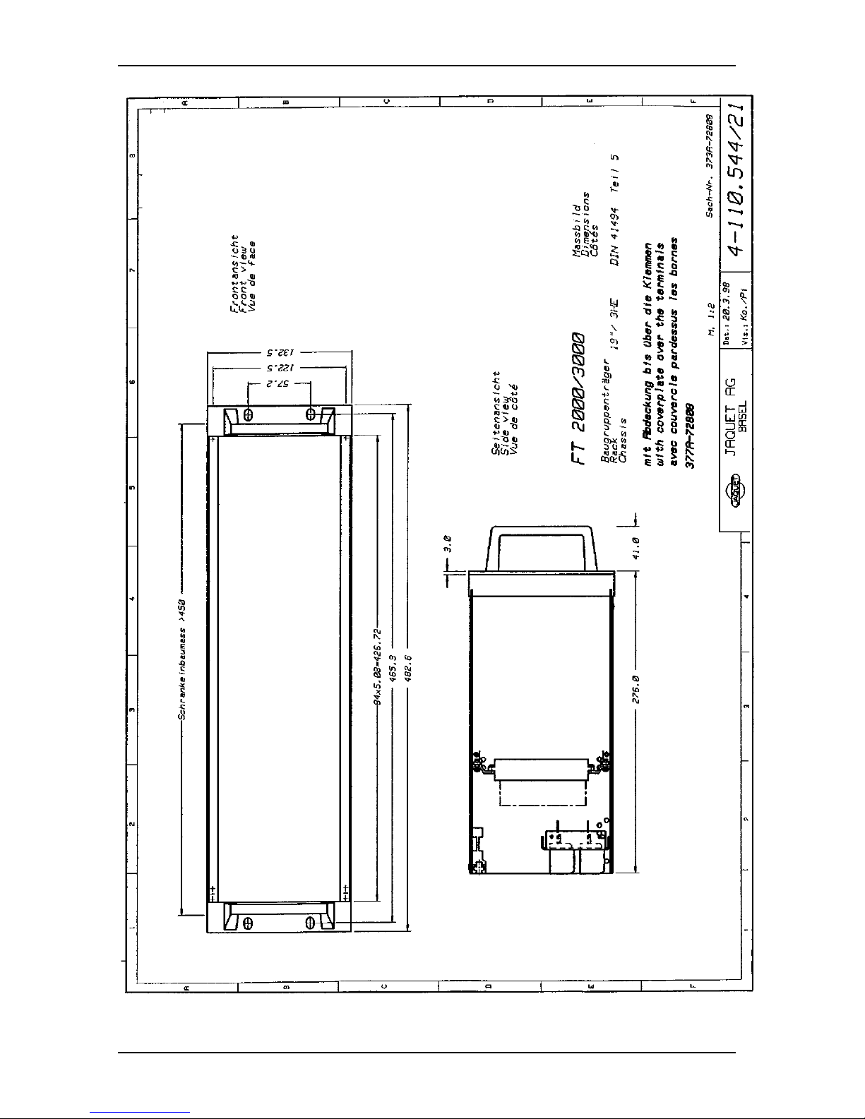
Operating Instructions FT 3000JAQUET AG
377E-63917 Rev 4.00 page 38 of 47

Operating Instructions FT 3000JAQUET AG
377E-63917 Rev 4.00 page 39 of 47
11 Circuit description
See also section 5
11.1 FTFU 3024 Motherboard and input card
11.1.1 Frequency measurement
The measurement chains for the 3 frequency measurements are implemented in hardware in the 3 ASIC’s.
The resultant floating point measurements <Absolut A>, <AbsolutB > and <AbsolutC> are fed to the m pu for further
processing.
Every measurement input is fed with one of 5 possible input si gnals configured via soft ware none, F1, F2, F3, F4.
A 10MHz quartz oscillator provides the timebase for the frequency measurement and speed monitors.
11.1.2 Speed monitors
The speed monitors are implemented in ASIC’s. Since there are 3 ASIC’s, 3 speed monitors are available.
The ASIC has two 32 Bit registers for measuring time and one 8 Bit register for pulses.
The resultant max measuring time is 859s with m ax processable frequency of 510khz.
The measurement resolution is 400ns.
11.1.3 Micro controller
internally 1 K Byte of RAM
8 channel, 10 Bit A/D converter
serial interface
Operation in expanded Multiplex mode
Quartz frequency 16 Mhz
Clock cycle 250ns
Address demultiplexer
32 K Byte EPROM (one time programma ble)
11.1.4 Supply
The supply voltage is derived from 2 redundant PSU’s, PS1 and PS2, that are separately fused. The 2 voltages are
monitored after the fuses by the mpu using A/D converters. The green front panel LED’s PS1OK and PS2OK are on
when the PSU’s are within tolerance:
Continuous overvoltage >= 38Vdc on the supply input causes the fuse to break
Continuous overvoltage > 33Vdc on the supply input can cause the fuse to break
Continuous undervoltage 13...18Vdc on the supply input does not affect the fuse
Continuous undervoltage < 13Vdc on the supply input can cause the fuse to break
Any relay on either the FTFU 3024 motherboard or the FTV 3090 relay card can be used to signal PSU status.
Relay 3 on the FTFU 3024 is allocated at the factory for this function.
After the fuses the 2 voltages PS1 and PS2 are diode decoupled to form a secure supply PS3. The diodes also provide
reverse polarity protection. Over voltage protection and storage capacitors ensure a secure 24V internal supply.
The power on surge of the FTFU 3024 is limited to 7A for 2.2ms by a 4.7 Ohm resistor.
The power on surge of the E01 input card is limited to 3.3A for 1ms by a 10 Ohm resist or.
The following supply voltages are generated on the FTFU 3024:
Ulogic = +5.00Vdc: Switched regulator to supply the logic, m pu, ASIC etc.
UFOut1 = +12Vdc: Linear regulator to supply the frequency output drivers.
UFOut2 = +12Vdc: DC/DC converter to supply the isolated frequency outputs.
Uin = +12 Vdc:DC/DC converter to supply the input module

Operating Instructions FT 3000JAQUET AG
377E-63917 Rev 4.00 page 40 of 47
11.1.5 Reset and non-maskable interrupt (NMI)
A hardware NMI reset circuit monitors the voltage Ulogic. The reset tim e constant is 200m s.
Following this time, the mpu carries out a reset routine.
A hardware NMI reset circuit monitors the input voltage +Vin to the Ulogic regulator.
If +Vin < 16V, NMI ouput = Low
+Vin > 16V, NMI o/p = High
The NMI input on the mpu reacts to a negative edge, ie if the input voltage sinks below +16V (eg if the supply is turned
off)
The NMI routine causes the following:
Termination of current measurement
mpu ports become high resistance to reduce current demand
NMI input to the mpu is monitored so as to initiate a reset routine
Should the supply suddenly fail, there is enough charge in the storage capacitor to ensure the above actions are
executed before the reset circuit becomes active.
11.1.6 Input amplifier
Current limited signal input, ac coupled with subsequent Schmitt trigger.
Sensor supply with protection diode, current limiting, shunt and differential amplifier for sensor current monitoring.
11.1.7 Sensor monitoring
Sensor monitoring is possible via static or dynam ic m onitoring or a com binati on of both. The front panle LED ‘M O’ is
on when no sensor fault has been detected. Otherwise the red LED lights.
Any relay on the FTFU 3024 or the FTV3090 relay card can be allocated to the sensor monitor functi on.
Relay 2 on the FTFU 3024 is allocated at the factory.
Static monitoring (realised in hardware on the input card)
A code resistor on the input card tells the mpu’s A/D converter what input card ty pe is instal led and the num ber of
sensors to monitor.
The current consumption of every sensor is monitored to be within the limits set via the front panel potentiometers.
Dynamic monitoring (by the mpu)
For multi-channel applications (2 of 3 or 1 of 2), the dynamic sensor monitor compares the sensors frequencies.
For 2 of 3 monitoring, the max permissible difference between 2 m easurem ents (as absolut e speed or % of nom inal) is
monitored ie Measured value A - Measured value B, Measured value B - Measured value C and Measured value C Measured value A. The sensor status is derived from these differences as follows:
C-A B-C A-B Sensor C Sensor B Sensor A
NOT OK NOT OK NOT OK NOT OK NOT OK NOT OK
NOT OK NOT OK OK NOT OK OK OK
NOT OK OK NOT OK OK OK NOT OK
NOT OK OK OK *OK *OK *OK
OK NOT OK NOT OK OK NOT OK OK
OK NOT OK OK *OK *OK *OK
OK OK NOT OK *OK *OK *OK
OK OK OK OK OK OK
* In this case the double difference is allowed.

Operating Instructions FT 3000JAQUET AG
377E-63917 Rev 4.00 page 41 of 47
For 1 of 2 monitoring the max permissible difference bet ween 2 measurem ents (as absol ute speed or % of nom inal) is
monitored ie Measured value A - Measured value B. The sensor status is derived from this difference as follows:
Difference > permissible value - the sensor delivering the higher value is assumed OK.
11.1.8 Module monitoring
The following functions can be logically configured via software to provide m odule m onitoring:
• System OK
• PS1 OK
• PS2 OK
• Sensor OK
If the module is OK or when the logically combined functions are OK t he green OK LED lights and the red LED is off.
Any relay on the FTFU 3024 or on the FTV 3090 can be used for signalling module status. Rel ay 1 on the m otherboard
is assigned at the factory.
11.1.9 Relay outputs
The motherboard has 3 relays with change over contacts. The relays can be assigned to various functions via soft ware.
11.1.10 LIMIT LED’s
The 4 green and 4 red LIMIT LED’s can be configured via software such that either red or green light at the
corresponding upper/lower set points.
11.1.11 Frequency generator
The frequency generator consists of a 32 Bit down counter in ASIC 3. From the zero state it is loaded from one of 2
software defined setable reload registers. 2 test frequencies can thereby be programmed and relia bly select ed.
A frequency change can only occur after one half period of the previous frequency, thereby avoiding any sudden
change to the dc average voltage of the test signal.
The frequency generator output from ASIC 3 is fed to all ASIC inputs F4 via t he input card.
11.1.12 Frequency outputs
Each of the 2 frequency outputs can be fed with one of 5 input signals - None, F1, F2, F3, F4, via software configurable
ASIC.
Following power up and as long as the reset routine is in progress, no output signals are provided.
11.1.13 Binary inputs
The binary inputs B1 and B2 have common reference with the m inus term inal on t he supply and have an internal pull
up resistor of 10KOhm to +5V. To active the input it need only be pulled down t o 0V (=mi nus term inal on the i nternal
24V module supply).
Binary inputs B3...B6 have a common floating reference. The isolation is via 4 optocouplers. To activate these inputs an
external supply is required.
If more than one input is given the same allocation, the input with the highest index is dominant (eg B3 in place of B2).
11.1.14 Test
The test frequency from the generator can only be switched to one of the 3 speed m onitors at any one t im e.
(See 9.1.2)
As long as the test frequency is connected, the green OK LED flashes (0.5s on, 0.5s off).
During activation/deactivation of the test, the original speed monitor status is retained such that no illegal operating
conditions can arise.

Operating Instructions FT 3000JAQUET AG
377E-63917 Rev 4.00 page 42 of 47
11.1.15 Direction of rotation discriminator
The determination of phase relationship between the input signals enables the directi on to be establi shed.
The required logic is in the ASIC’s. The mpu controls the display and eventual relay status. The front panel LED’s BW
(backwards) and FW (forwards) signal the direction of rotation.
11.1.16 Lamp test
The lamp test applies to all FTFU 3024 and eventual auxiliary module LED’s. It is activated via the configured binary
input. During testing only the LED’s are affected. The relays remain under control of the measurem ent sy stem .
11.2 FTW 3013 - A/D converter auxiliary module.
11.2.1 Supply
The supply is fed in via the local bus.
The power on surge is limited to 0.1A for 155ms by a 330 Ohm resistor.
With this module, the current limiting resistor is short circuited after approx. 0.8s following power up.
11.2.2 Analog outputs
Three separate isolated converters are available to provide dc signal outputs. Each output is controlle d by a
12 Bit digital value from the local bus, derived from the PWM (pulse width modulation) output from the ASIC.
The PWM frequency is dependent upon the output value and is 312Hz min. A subsequent single ended low pass filter
lampens the ripple to less than 0.1%.
An additional single ended digital low pass filter with software configurable time constant enables further suppression
of fast changes to the output signal.
A noise filter suppresses external interference on the line.
11.3 FTV 3090 Relay card
11.3.1 Supply
The supply is fed in via the local bus.
The power on surge is limited to 0.1A for 155ms by a 330 Ohm resistor.
With this module, the current limiting resistor is short circuited after approx. 0.8s following power up.
11.3.2 Relay outputs
The FTV 3090 possesses 4 extra relays each having change over contacts. The relays can be assigned via software to
various functions.
11.4 FTK 3072 Comms module
11.4.1 Rack bus
The rack bus is laid out as a RS 485 serial data bus and provides communi cations between the FTK 3072 and t hose
modules equipped with a corresponding interface:
• FTFU 3024 motherboard
• FTM 3000 micro terminal
The rack bus connections to the modules are via the card connectors.

Operating Instructions FT 3000JAQUET AG
377E-63917 Rev 4.00 page 43 of 47
11.4.2 RS 232 interface
The interface is accessed via the front panel D9 connector on the FTK 3072.
Transfer rate: 2400 Baud
Parity: None The connection diagram shows the names with respect to
Data bits: 8 the equipment interface. RXD on the FT3000 must be
Stop bits: 2 connected to RXD on the PC, and also for TXD.
Connector: D9
The interface operates at the standard voltages. Protection against external overvoltage is provided.

Operating Instructions FT 3000JAQUET AG
377E-63917 Rev 4.00 page 44 of 47
12 Maintenance
The electronic boards do not need any special maintenance activity.
12.1 Periodic test
12.1.1 Description
The periodic test is used for proving the capacity of the system to detect an overspeed and to transm it the detection.
This has to be applied to the Overspeed Protection System, and to the Trip Chain Control System if available.
The periodic test is realised for each channel separately. It is a serious error trying to test more than one channel at one
time. It would generate systematically an overspeed trip.
By asserting a binary input of the system the corresponding channel is te sted. Each channel has an own logi c input.
12.1.2 IEC 61508-2-3 specifications
The periodic test is necessary for reaching the IEC 61508-2-3 requirements, then obligatory.
The periodicity of this test must be ≤ 3 months.
Between each channel test, a no test delay of 10 minutes must be implemented.
The execution of the test removes the sensor signal on the tested channel and replaces it by the signal coming from the
on the module FTFU3024 implemented frequency generator configured to a frequency about 1% higher than the
overspeed frequency. The relay corresponding to the overspeed set point must de-energise. The effect of the deenergised overspeed relay must be checked by the end user.
Periodic test for the Saignal Monitoring System :
Mostly of the integrated fonctionalities of the FTBU 3x34 card are on board redundant. Espescially the inputs stages of
the signal monitoring paths. The execution of the test replaces the input logic combination witch is needed to generate a
trip on the OUT output, and the output is asserted (relay OUT deenergized). The effect of the deenergized relay must be
checked by the end user.

Operating Instructions FT 3000JAQUET AG
377E-63917 Rev 4.00 page 45 of 47
12.2 Trouble shoting :
Trouble shoting is needed when the S + M + P Alarm signal is asserted, or when the system behaviour under periodic
test condition is false.
12.2.1 Procedure for the OSPS
The Following procedure has to be applied :
- If the red MO LED of a channel is on : (Sensor Monitoring)
Exchange the channel module (see chapter Module exchanging)
If the trouble stays, replace the original channel module and exchange the sensor.
If the trouble stays, exchange the channel module and the sensor.
If the trouble stays, check the rack and sensor wiring,
check the 3 sensor signals, exchange the sensor if signal false.
- If the OK LED of a channel is red : (System Monitoring)
Exchange the channel module (see chapter Module exchanging)
If the trouble stays, check the rack wiring.
- If the PSI or PSII led is off on each channel : (Power suply Monitoring)
Exchange the corresponding power supply
If the touble stays, check the rack wiring.
- If the PSI and/or PSII led is off on one channel : (Power suply Monitoring)
Exchange the corresponding channel module
If the touble stays, check the rack wiring.
- If no red LED is on, and no PSI/II LED off and the periodic test for one channel is false :
Exchange the corresponding channel Module
If the trouble stays, remove the new module, check the rack wiring, and terminal
connections.
After a repair, a periodic test must be performed for each channel.(see chapter Periodic test).
Description of the diacgnostic who’s continiously performed in the system :
- System monitor: If a system failure occurs (CPU Test, Configuration parameter integrity test, Process
parameter integrity test and Service parameter integrity test , both power supply out of range, auxiliary
module not present, FPGA not programmed) the red Led MO\ on the front plate goes on and the green
Led MO goes off or blinks depending if the failure occurs in process mode, configuration mode or
service mode. The Module OK relay de-energise. All the relays on FTFU3024 and FTV3090 deenergise, the analog outputs goes to 0 mA/V. So in a 3 channel system, when trip contact is open to trip,
the channel goes in a safe state.
- Supply monitor : If a supply failure occurs (power supply voltage out of the 18...33VDC range) the
corresponding green Led PS1 or PS2 on the front plate goes off and the Module OK relay de-energise.
The case of an out off range of both power supplies is taken in account by the system m onitor.
- Sensor monitor: The sensor and the line between sensor an rack is monitored by the static
monitoring. The signal delivered by the sensor is also monitored by the dynamic monitoring. If a sensor
failure occurs in one channel the relay corresponding to the overspeed set point de-energise i.e. takes the
state as in overspeed : the channel goes in a safe state.

Operating Instructions FT 3000JAQUET AG
377E-63917 Rev 4.00 page 46 of 47
12.2.2 Procedure for the TCCC :
The Following procedure has to be applied :
- If the OK LED of a channel is red : (System Monitoring)
Exchange the channel module (see chapter Module exchanging)
If the trouble stays, check the rack wiring.
- If the PSI or PSII led is off on each channel : (Power suply Monitoring)
Exchange the corresponding power supply
If the touble stays, check the rack wiring.
- If the PSI and/or PSII led is off on one channel : (Power suply Monitoring)
Exchange the corresponding channel module
If the touble stays, check the rack wiring.
- If no red LED is on, and no PSI/II LED off and the periodic test for one channel is false :
Exchange the corresponding channel Module
If the trouble stays, remove the new module, check the rack wiring, and terminal
connections.
After a repair, a periodic test must be performed for each channel.(see chapter Periodic test).
12.2.3 IEC 61508-2-3 specifications
The mean time to repair is fixed to 8 hours. The end user is responsible for reaching this repair time and has to
realise the needed conditions por reaching it. The 8 hours include :
- 2 hours for the comeback of the service people.
- 2 hours for the trouble analysis.
- 2 hours for the correction definition.
- 2 hours for the trouble correction.
12.3 Module exchanging :
12.3.1 General
The repair is performed by exhanging modules. The exchanging module set i ncludes :
- 1 sensor
- 1 configured channel modul including :
1 FTFU 3024 card, if used one FTV3x90 card and one FTW3x13 card.
- 1 power supply if used
- if used, one TCCC channel modul FTBU 3x34
The electronic modules are field hot-replacable, the sensor too. Generally, one additional sensor is premonted in the
process so one sensor exchange can be realised without stoping the main process.
Only modules in one channel can be removed at one time. It is a serious error trying to exchange modules in more than
one channel at one time. It would generate systematically an overspeed trip.

Operating Instructions FT 3000JAQUET AG
377E-63917 Rev 4.00 page 47 of 47
12.3.2 IEC 61508-2-3 specifications :
The modules can not be realocated one channel to an other.
An exchanging module set has to be available at the installation so that the mean time to repair can be reached (8 hours).
This module is configured in stock. After a repair where the in stock module were used, a new configured module must
be set in stock. The burned-in Modules (100 Hours 50°C) are supplied from the OSPS supplier, the integrator
configures the module and set it in stock at the installation.
Only trained service people is allowed to performe any maintenance activity : Periodic test, trouble shooting. Trained
people means people who have a good knowledge of the installation and maintenance procedure of the system, people
who know the significance of a 2oo3 system, people who have at one’s disposal all the 4 core system descript ions :
- The bloc fonction description of the system
- The face description of the system
- The terminal description of the system
- The operating instructions manual of the system
13 Storage
The long term storage temperature range is -25 ... +85ºC.
The short term storage temperature range is -40 ... +90ºC (max one day at any time, without any m echanical loading)
If the unit is suddenly cooled, condensation may occur, which considerably reduces the insulati on resistance.
14 Warranty
The FT3000 is guaranteed for 12 months from the ship date. Please see JAQUET’s full terms and conditions.
15 Drawings
Description Type Dwg. Nr.
Block circuit diagram 4-110.505
Lay-out of the rack 3-110.545
Occupancy and wiring of rack 3-110.536
Dimensions:
• Rack 4-110.544/21
• Modules 4-110.544/2
Connection diagrams of the modules:
• Motherboard FTFU 3024 4-110.531/23
• Frequency to current converter FTW 3013 4-110.531/24
• Relay module FTV 3090 4-110.531/25
• Comms module FTK 3072 4-110.531/26
• TCCC card FTBU 3x34 4-110.531/30
 Loading...