


Digital Thermometer
UNI-SENSOR 701A
Operating Instructions
Ver. 2.0

UNI-SENSOR 701A Operating Instructions
Table of Contents
Introduction.......................................................................................................1
1. Precautions...............................................................................................1
2. Features ...................................................................................................2
3. Checking the Thermometer ......................................................................2
4. Specifications............................................................................................2
5. How to Operate the Thermometer and Descriptions of the Functions......3
6. How to Use Each Sensor (Optional).........................................................7
7. Sensor Group for Various Applications .....................................................8
8. Maintenance ...........................................................................................9

1
Introduction
Thanks for purchasing a JAPAN UNIX UNI-SENSOR 701A digital thermometer.
Read the Operating Instructions thoroughly and understand the descriptions well before using
this UNI-SENSOR 701A digital thermometer to operate it correctly.
CAUTION
♦ No p art of this document may be reproduced or photocopied in any form without prior
notice.
♦ The contents of this document are subject to change without notice in the future.
♦ Although we have taken all possible measures to ensure the descriptions of this
document, please do not hesitate to contact us if you find anything wrong such
as an error.
1. Precautions
Before using the UNI-SENSOR 701A digital thermometer, be sure to read the following
cautions and understand them well.
Use the UNI-SENSOR 701A digital thermometer under the environment
that is regulated with the specifications only. Otherwise, it may lower the
reliability of the thermometer or cause the thermometer to malfunction.
If you do not use the thermometer for a long time, the battery may leak.
Please remove the battery from the thermometer.
The case of the thermometer is made of ABS resin. Be careful not to
bring the case to any substance whose temperature is high so that it
cannot be deformed.
Organic solvent such as thinner, benzine and alcohol may deform the
thermometer. Do not apply such solvent to the thermometer.
CAUTION
CAUTION
CAUTION
CAUTION

2
2. Features
This UNI-SENSOR 701A is a product of outstanding safety and reliability. Its main features
are shown below.
① Highest resolution 1.0°C and low cost
High response speed allowing your quick operation
③ Sensor that can be connected to the main unit directly
④ Extension compensating lead wire that allows the thermometer to be used for various
applications
⑤ A wide choice of sensors you can select according to your purpose
⑥ High-precision automatic cold-junction compensating circuit that improves the
performance
3. Checking the Thermometer
Take out the UNI-SENSOR 701A from the package at first. Check the supplied parts one by
one from the following figure to see if you have all parts and if any of them is not damaged. If
you do not have any of them or if any of them is damaged, contact the dealer from which you
have purchased the thermometer.
4. Specifications
Model name UNI-200
Input TYPE/K (CA)
Resolution 1.0°C
Measurement range - 65°C to + 1,000°C
Display precision Display tolerance: ± 0.3 % of rdg ± 2 dig
Temperature coefficient: ± 0.03 % of FS/°C
Sampling frequency 3/second
Cold junction compensating precision ± 0.5°C (at 25°C ± 10.0°C)
Power supply Type 006P battery × 1
Operating time Continuously 100 hours or more
Operation switches ON, OFF, Hold, Battery Low automatic display
Operating environment 0 to 40°C, 20 to 85 %RH (No condensation)
Mass of the main unit Approximately 180 g
Dimensions 185 (W) × 35 (H) × 23 (D) mm
Cover Main unit
UNIX-SENSOR 701A
UNIX-200
POWER
HOLD
MODE
Sensor for the iron tip
UNI-200 UNI-9

3
5. How to Operate the Thermometer and the
Descriptions of the Functions
5.1 How to insert a battery
• Open the battery lid.
• Connect the power cable to the battery.
• Insert the battery.
• Close the battery lid.
CAUTION
If you do not use the thermometer for a long time, the battery may leak.
Be sure to remove the battery from the thermometer.
5.2 Turning on or off the thermometer
• Connect the sensor to the main unit.
When you press the key, all of the display items
light for approximately one second, and the
thermometer starts measuring.
When you press the key again, the thermometer is
turned off.
When you press the POWER key anytime during measurement, the thermometer is turned off.
When you turn on the thermometer, it enters the normal measurement mode.
* In this document, the state into which the thermometer is put at power-on (no function
appears on the left side of the display) is referred as to the “normal measurement mode.”
9V
−
+
−
+
POWER
HOLD
MODE
POWER
POWER
POWER
MAX
MIN
HOLD
AVG

4
5.3 How to measure the temperature of an iron tip
• Melt wire solder with the iron tip, and put the iron tip to
the center of the sensor to measure its temperature.
CAUTION
It takes a while for the temperature to
become stable after solder is melted.
5.4 Detaching the probe
• Push the probe stopper and pull the probe out.
POWER
HOLD
MODE
POWER
HOLD
MODE
Push here.

5
5.5 Various HOLD functions
Selection
(Maximum value HOLD function)
Selection
(Minimum value HOLD function)
Selection
(Average value HOLD function)
Maximum temperature display mode
A normal measurement value is displayed.
Confirmation
Cancel
Confirmation
Cancel
Minimum temperature display mode
A normal measurement value is displayed.
Average temperature display mode
A normal measurement value is displayed.
HOLD function
The current measured temperature data is held
and displayed.
“HOLD” lights on the display.
Maximum value HOLD function (MAX/HOLD)
When “MAX” and “HOLD” are lighting on the display, the
thermometer holds and displays the maximum
temperature data while constantly updating the maximum
temperature data being measured.
If an error occurs, the error message is held and
displayed.
The maximum
temperature is displayed.
Minimum value HOLD function (MIN/HOLD)
When “MIN” and “HOLD” are lighting on the display, the
thermometer holds and displays the minimum
temperature data while constantly updating the minimum
temperature data being measured.
If an error occurs, the error message is held and
A
verage value HOLD function (AVG/HOLD)
This is the function for displaying the average value
obtained during the desired time period.
When “AVG” is lighting on the display, the thermometer
internally holds the temperature data being measur ed .
The actual measurement temperature data is displayed.
A
normal measurement
value is displayed while
the average value is being
obtained.
Average value displayed while “AVG” is lighting
When you press the HOLD key, “AVG” and “HOLD”
light on the display, and the thermometer calculates the
average of the measurement temperature data held with
it internally, and holds and displays the average value.
You can calculate the average value of the measured
temperature data for up to five hours. After a lapse of
five hours or more, this function is cancelled.
If an error occurs during averaging, the error status is
held and displayed.
Confirmation
The minimum
temperature is displayed.
6
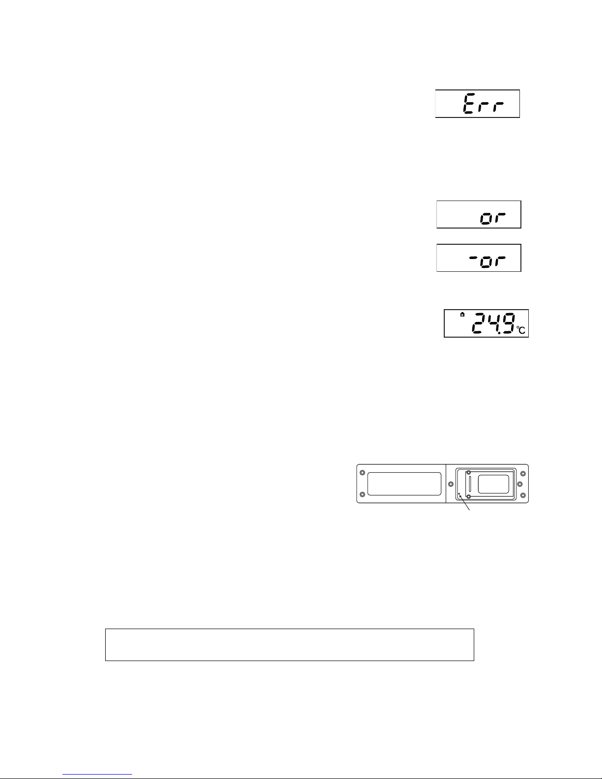
5.6 Error messages
(1) Indication of the broken sensing edge
If the sensing edge of the probe is broken or if the probe is not
connected to the thermometer, “Err” appears on the display as
shown in the right figure.
If this message appears on the display, replace the probe with a
new one or connect the probe to the thermometer.
(2) Over range indication
If the measured temperature exceeds the measurable range, “or” or
“-or” appears on the display as shown in the right figure.
If the sensing edge of the probe is broken, this over range error may
appear also. If the temperature being measured is within the
measurement range clearly , check t he probe. If the indicated value
gets unstable abnormally, check the probe also.
(3) Indication of decrease in the battery power
When the remaining power of the battery decreases, and then the
remaining power level becomes approximately five hours, “B,” which
indicates decrease in the battery power, lights on the display. The
entire display is set to flash when the remaining power level
becomes approximately 30 minutes.
Note that when the battery power decrease indication appears
varies depending on the battery type and/or the used environment.
When the indication of decrease in the battery power lights, replace
the battery with a new one as immediately as possible.
(4) What to do if the thermometer malfunctions
If the display or the thermometer itself
malfunctions, push the reset switch of the battery
storage section with a thin stick or similar tool.
When you press the reset switch, the
thermometer is put into the state in which it is put
at power-on.
If the thermometer does not operate normally
even after you push the reset switch, the
thermometer may have broken down. Contact
a dealer from which you have purchased the
thermometer or us.
CAUTION
When the battery is exhausted completely, the thermometer does not
display the low power indication.
Reset switch

7
6. How to Use Each Sensor (Option)
① How to put the surface sensor to the target
Put the surface sensor to the contact surface of the
target vertically.
Note that the thermometer cannot detect the
correct temperature if the contact surface of the
target is not smooth or flat.
(UNI-1)
② How to connect the extension kit
(UNI-4)
③ How to measure the temperature of a board
Use a heatproof tape to paste the sensor onto the
place of a board whose temperature you want to
measure.
(UNI-8A)
④ How to measure the temperature of a solder bath
Push the sensor through the solder bath to
measure the temperature of the inside of the
solder bath.
(UNI-2)
B
90°
POWER
HOLD
MODE
POWER
HOLD
MODE
HOLD ON OFF

8
7. Sensor Group for Various Applications
Model name Shape Tip of the
sensor
Operating
temperature
Feature/Application
UNI-9
Sensor for an iron tip
(Supplied with the
thermometer))
Normal
temperature to
+ 500°C
• You can measure the
temperature of an iron tip
correctly.
UNI-1
Surface sensor
(optional)
- 50°C to +
200°C
• The certain ground contact
pressure is obtained with the
spring mechanism to allow
the thermometer to detect the
correct surface temperature.
• Durability of the contact
surface of the sensor is
higher than that of the
competitors, and the life is
longer also.
UNI-8A
Pasting type sensor
(optional)
- 30°C to +
200°C
• Use a heatproof tape to paste
the sensor at a position
whose temperature you want
to measure.
• High-sensitive sensor that
can measure the temperature
in real time
• The sensor is film-laminated
and its strength is increased.
UNI-2
Bar type sensor
(optional)
- 100 °C to +
500°C
• Push the sensor through the
solder bath to measure the
temperature of the inside of
the solder bath.
UNI-4
Extension kit
(optional)
• Use this kit to measure the
temperature of a substance
at a high position or narrow
place.
• This kit is useful to measure
the temperature of a
substance whose
temperature or humidity is
high.
* The specifications, design and/or size are subject to change
without notice due to continual improvements.
40
3
150
3φ
Spring

9
8. Maintenance
About storage
When you store the thermometer, avoid places (environment) subjected to:
• Direct sunlight
• High temperature
• High humidity
• Vibration
CAUTION
♦ The case of the thermometer is made of ABS resin. Be careful not to bring it
close a substance whose temperature is very high so that it cannot be
deformed.
♦ Organic solvent such as thinner, benzine and alcohol may deform the
thermometer. Do not use any of them.

HEAD OFFICE
21-25, Akasaka 2-Chome, Minato-ku, Tokyo 107-0052, Japan
URL http://www.japanunix.co.jp.
 Loading...