


FOR
QUICK
REFERENCE
AND SPARE
PARTS
NUMBER
ORDERING,
WITH
RECORD ENGINE
PREFIXES
HERE
Jfr
INDUSTRIAL
ENGINES
MODELS,
Reference
412, 413, 5
TYPE
Book, Diagraffis,
I
A 6
Printed by East Cheshire
Pri
Spare
Parts
Lists
sBiP/04
61ffi

JD
MODE,LS
412,413,,5€d6
INDT]STRIAL
E,NGINE,S
Genera,
TYPE,
1
I DescriPtion,
Running
',fl,
I nstructions
and Spare
a,nd
M aintenance
with
Pa,rts
Diagrams
List.

GENERAL DESCRIPTION
The crankcase
a rigid
a
each revolution.
aluminium
trough into
through metering
The
crankshaft is
roller
or
rod assembly
The
big-end is split and
The piston
rings,
fitted
oil
ball bearings of large
connecting-rod is
one o{
in
scraper rirq
bottom ring groove
gudgeon
The
in
gudgeon
the
The
cylinder is
circumferr:ntial
The cylinder
assist
cooling.
joint
thc
The
camshait
gears.
spur
'lhe
pinion
The inlet
adjustment
tappet
heads.
Lubrication is
and
-very
crankcase is- provided
crankcase release,
The
th.rottle
choke,is
A
centrifugal governor
shlft and. operates.the
and
starting
Peen 2
is made
which the
are
is of die
rvhich is a
top
the
pin
bosses.
madc
fins of
head
It is
betrveen
is
is rnachined
and
exhaust,cams
is effected
fhc
by
eihcient,
is operated
fitted
to
lever is
base rvhich
This
holes
made of high quality
very carefully
fitted
cast aluminium
groove
above
is located
is made
the
made
whole of
JAI'
_affording
ensuring a
facilitate
fitted,
from high-grade
forms the oil
dippcr on
trough is
kept at
which connect to
dimensions.
balanced.
stcel
with a phosphor
with
white metal steel
aluminium.
the end of the
constant level
the
steel, and is
The
bronze small-end
alloy.
special
with the fåce
the
from
special
detachable and
cylinder ancl head.
from meehanite
from steel
by
pa.tcuted
with the
by a centrifuga,l governor.
is driven
throttle by
taper chrome-plated
gudgeon pin.
by
a circlip at
close
shape for
marl<ed TOf
grained
Drain holes åie
each end and ls {ully floating
cast iron and
cooling.
from an aluminium
fitted
alloy,
and meshes
operate
the fitting of
the cam gear
ample
directly on
dipper
system
supply to all
difierent
is encloscrl
well-known
clean
engine and
starting
when engine is
by a spur wheel
which is operated
simple
mechanism.
sump. In the
It is mounted
connecting rod dips at
main
crankshaft and
backed shells.
It is fitted
alloy,
with a
and is driven
with
and is
]AP
economy in oil.
meshing
against
by
sump.
carried
with compression
ring and
uppelmost, and an
drilled in the
is provided
deeply {rnned
§asket-wirich
the camshaft.
the tappets.
thicknå§s
and running
entirely automatic
working
vacurrru
A
hand operated
cold.
with
A slow running
the governor
is
base
oil
fltted
bein[ fed
on
taper
connecting-
bush. The
must be
forms
by heavy
Tappet
discs uiråer
in oil.
parts.
System
cam-
the
arrn.
on
with
to
'fhe
and
The flywheel
The
cooling
cylinder head
for
The
of
The
Attached
purpose.
this
cowl is designed
the cylinder and cylinder
oil filler cap on the side
is a
Ian
air is
and
dipstick,
is of
supplied
portions of the cylinder, which are
These
iron
cast
by this
fins should be kept clean for efficient cooling.
give
to
a cooling
head.
having high level mark.
tsOTTOM END INDICATES
is fitted
and
fan,
directly
creates a
which
draught to
of the crankcase is
DANGER LEVEL.
on
cranksheft.
the
draught
over tho
correctly
necessary portiont
the
of
the
screwed
THE DIPSTICK
ALWAYS
flnned
type.
XNBP MOVE THE
CAP
WHEN THE
The engine base
A carburetter has been
jets
the
It
smooth running
Jets,
water.
22 to 25
The damper on the
should not
is correctly
fi,lters,
This
for
etc.,
can
maintenance
ENGINE
must
be
specially designed for each engine. The setting
be interfered
at the works,
set
of the
engine.
may
be simply
governor arm is
standing
occasionally require cleaning to remove dirt
friction on the spindle. Great
ing
lVhen commerclal
this,
as
much friction will
too
petrol
§poon of eng,lne otl wlth
mlxed.
COLD
(")
fully
(å)
(r)
(d)
(r)
§TARTING.
petrol filter tap by
Open
Each filter
in for
the slow
Slip
Push the carburetter
only.
Turn
When
wpwørds
OFF,
is
or
fitted
fully
with a tap
running lever into
engine slowly until compression is felt.
compression
direction.
is felt,
IMPORTANT.-Always
do not attempt
When engine
U)
(g)
engine commencss
When
choke lever forward to
to start
has
started
HOT STARTING.
To facilitate restarting
a hot
inlet pipe. When starting difficulty
a
crankshaft
rich
The air
tap still open, crank engine
the
started and
has
mixture.
the
slowly
mixture. During this operation the
should be
choke
is running evenly, close the tap to
times to clear the induction system
few
left
IS RUNNING.
level
when checking or re-filling
with except by an experienced engineer.
and any slight alteration may upset the
done by blowing
and
carburetter
to
care, however, must be exercised in adjust-
prevent
ls used,
gallon
one
turning in anti-clockwise direction.
which
out for ON, to ensure
position
air choke levcr to close choke
give
the starting
pull
starting
continuous turniag.
by
release the slow running
pick
to
open choke.
a release tap has been
engine
open
occurs, open the tap
at all times for starting
to start in the usual
air
through them. See
parts list.
prevent hunting
the throttle
lt le
advlsable
putting extra
by
opening
to
add
one table-
of fuel. Thta should be well
requires to be screwed
to
proof
leak
partly
close the throttle.
operation.
for cold
handle a
handle up smartly to start;
up speed,
puli
sharp
lever.
the Carburetter air
provided
and rotate
of
excessively
throttle should be left wide open.
hot
engines. With
manner. A{ter engine
prevent
weakening of
oil.
pages
fully.
either
starting
pull in
on the
the
Pecn 3
of
or
(
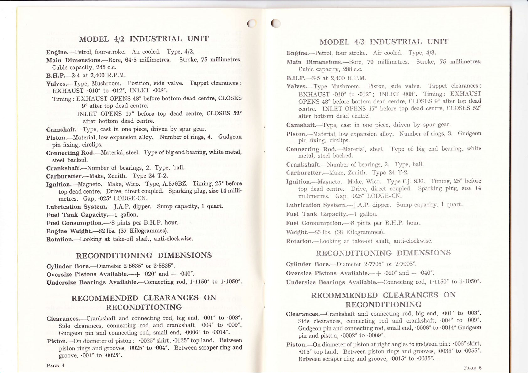
MODEL
Engtne.-Petrol,
Maln
Dimensions.-Bore,
Cubic
capacity,
B.H.P.-2'4
Valves.-Type,
EXHAUST
Timing:
Camshaft.-Type,
Pieton.-Material,
pin fixing,
Connectin§,
backed.
steel
Crankshaft.-Number
Carburetter.*Make,
Ignttton.-Magneto.
dead
top
metres.
Lubricatlon
Tank
f,'uel
Consumptlon.-'8
Fuel
Engtne
Wel§ht.--{2
Rotatlon.-Looking
four-stroke.
245
at 2,400
I\{ushroom.
to
'0l0"
EXHAUST
after top
9"
INLET OPENS
bottom
after
cast
low expansion
circlips.
Rod.-Material,
centre.
Gap,'025'
Syetem.-J.A.P.
Capaclty.-l
at take-ofi
INDUSTRIAL
412
Air
millimetres.
64'5
c.c.
R.P.M.
Position, side
'012',
INLET
OPENS
in one
48' before
dead centre.
before top
17'
dead centre.
piece,
alloy. Number
steel. Type
of bearings,
Zetith. Type
Make, Wico.
direct
Drive,
LODGE-CN.
dipper. Sump
gallon.
per
pints
(37
lbs.
Kilogammes).
shaft,
UNIT
cooled. Type, 412.
Stroke,
valve.
'008".
dead
by
capacity'
hour,
dead centre,
centre, CLOSES
spur
of ringe,
bottom
driven
of big endbearing,
Type, ball.
2.
24 T-2.
A.57682.
Type,
coupled. Sparking
B.H.P.
anti-clockwise.
millimetres.
75
Tappet clearancer
CLOSES
52'
gear.
4.
Gudgeon
metal,
white
size
quart.
beforo
14
milli-
Tirning, 25"
plug,
I
INDUSTRIAL
MODEL
Engine.-Petrol, four stroke.
Maln Dimensions.-Bore, 70
capacity, 288 c.c.
Cubic
:
B.H.P.-3.5 at
Valves.-Type
EXIIAUST
OPENS 4Bo bcfore
centre. INLET Ol'IiNS
after bottom
Camshaft.-Type, cast
Piston.-Material, Iow
2,400
Mushroom.
'010" to
413
It.P.Nt.
'012"
bottom
dead centre.
in one
expansion alloy.
Air coolcd.
millimetres.
Piston,
17"
side
INI-IiT
;
clead centre,
be{ore top
piece, driven
1'ype,
val.ve. Tappet
'008'.
Number
UNIT
,t/3.
Stroke,
Timing:
CI-OS}iS
dead centre,
by spur
9"
rings, 3. Gudgeon
of
millimetres.
75
clearances
IIXHAUST
after top
CLOSES
gear.
:
dead
52'
pin fixing, circiips.
25o
whito
before
siz;e
14
Connectln§ Rod.--'Material,
metal, steei backed"
Crankshaft.-Number
Carburetter.--1,{ake,
of
Zcnitir.
steel.
bearings,
Type 24'l-2.
Ignition.--ltagneto. l'I;rl<e, Wico.
dead ccntre. I)rive,
top
millimetres. Gap,'025"
Lubrication S-v*stem.-.J .A.I'].
Fuel Tank Capacity.--l
Fuel Consumption.--'8
Weight.--S3 lbs.
(i38
I(ilogrammes).
Rotation.-I-ooking at rake-olI
direct
I-riI)Gtt-CN.
dipper.
gallon.
per u.H.P.
pints
shaft,
Type
2. fype,
Type CJ.
couplecl.
Sump
anti-clockrvise.
of big
ball.
936.
Sparking
capacity,
hour.
en<l bearing,
Timing,
plug,
quart-
I
RECONDITIONING
Cyltnder
Oversize
Underslze
Bore.-Diameter
Pietons
Bearin§s
Avallable.-+
Avatlable.-Connecting
RECOMMENDED
RECONDITIONING
Clearances.-Crankshaft
clearances,
Side
Gudgeon
Piston.-On
rings ancl
piston
groove,
4
Pecn
pin and connecting
diameter
.001'
connecting
of
grooves, '0025' to
to'0025".
2'5635'
or 2'5835'.
'020'and
CLEARANCES
and connecting
rod
rod,
piston
'0025'skirt,
:
DIMENSIONS
'040'.
f
rod, l'1150"
rod, big end,
and crankshaft'
small end,
'004'. Between
'0006" to
'0125" top land'
to l'1050".
ON
'001"
'001'
'0014'.
scraper
'003'.
to
to
'009'.
Between
ring and
RECONDI']TIONING
Cylinder Bore.-DiiLmcter
Oversize
Undersize Bearings
Pistons Available.-
Available.-Connectirrg
RECOMMENDED
RECONDITIONING
Clearances.-Crankshaft
clearances,
Sicle
Gudgeon
pin and
pin and connecting
piston, '0002" to
Piston.-On rliameter
'015" top
Between
land. Betrveen
scraper ring
connecting
piston at right
of
and
2'77O5"
connecting
and
rod, small
'0009".
pistorr rings
groove,
DIMI'NSIONS
2'7905".
or
+
'020'
and
+
'040".
rod, 1'1150"
CLEARANCES
rod, big
and cranksha{t,
rod
'0006"
end,
gudgeon pin: '006"
to
angles
grooves, '0035'to
and
'0015" to
'0035'.
end,
to
t'1050".
to
ON
to
'001'
'004' to
'0014"
Gudgeon
'003'.
'009".
skirt,
'0055'.
Pr,cn 5

(
MODEL
En§lne.-Petrol,
Maln
Dlmenslone.-Bore,
capacity,
Cubic
B.H.P.-4'5
Valves.-Type,
EXHAUST
Timing
-
Camshaft.-Type,
Pleton.-Material,
pin fixing,
Connectln5i
white
Crankshaft.-Number
Carburetter.-Make,
Ignttlon.-Magneto.
dead
top
millimetres.
Lubrlcatlon
Tank
Fuel
Consumptlon"-'9
Fuel
Wetght.-122
four-stroke.
412 c.c,
at 2,200
R.P.M.
Mushroom.
'020';
EXHAUST
I
CLOSES
INLET
circlips.
Rod.-Materia.l,
metal, steel
OPENS
after
52'
cast
low expansion
backed.
Zenith.
Make,
centre.
Gap,'025"
System.-J.A.I'}.
Capacity.-l
(55'5
lbs.
INIÆT
in
of bearings,
Drive,
RECONDITIONI}{G
Cyllnder Bore.-Diameter
Overelze
Underelze
Plstons
Bearing,s
Avallable.-+
Avallable.-Connecting
RECOMMENDED
RECONDITIONING
Clearances.-Crankshaft
clearances,
Side
Gudgeon
pin and
Plston.-On
skirt,
'017'
'0055'. Between
6
Prae
pin and connecting
piston,
diameter
connecting
'0002'to
of
top land,
scraper
INDUSTR.IAL
5
Air-cooled.
millimetres,
80
Position,
OPENS
after
9"
17'
bottom
piece, clriven
one
side
'010'.
48" before
toP
before
dead
alloy'
steel.
ton
40-45
Type,
2'
24
Type
direct
Typ" CJ,
coupled'
Wico.
LODGTI-CN.
dipper. Sump
gallon.
per
pints
Kilogrammes).
3'170"
ts.H'P.
or 3'190'.
'020' and
CLDARANCES
and connecting
and
rod
small
rod,
'0009'.
piston at right
Between
ring and
piston rings and
groove, '0015'to
UNIT
Model
Type,
stroke,
valve'
bottom
centre.
dead
dead
top
centre.
spur
by
Number
Type
taper
T-2.
936.
Sparl<ing
capacity,
hour.
DIMENSIONS
f
rod, 1'1150"
rod,
big-end
crankshaft,
end '0005'to
to
angles
5.
82
Tappet
dead
centre,
gear.
rings, 3. Gudgeon
of
of
big
roller.
Timing,
plug, size
2
'040".
ON
'001' to
'004" to
'0014" Gudgeon
gudgeon
grooves,
'0035'.
millimetres.
clearances:
centre,
CLOSES
bearing,
end
belore
20o
pints.
to l'1050".
'0025'.
'009'.
pin
'008'
:
'0035'
14
to
Type,
Stroke,
valve'
centre'
dead
top
by
big
of
taper
936'
CJ'
capacity,
hour'
f
rod,
UNIT
Model
102
Tappet
centre;
gear'
spur
rings,
of
bearing'
end
roller'
Timing'
Sparking
'040"'
1'3655'
6'
4' Gudgeon
plug'
pints'
3
ON
INDUSTRIÅL
MODEL
Engine.-Petrol,
Dimensions.-Bore,
Maln
Cubic
capacitY
B.H.P.-5'5
Valves.-Type,
EXHAUST
Timing:EXHAUSTOPtrNS48'beforebottomdeadcentre;
-
Camshaft.-Type,
Piston.-Material,
pin
fixing,
Connectln§
metal,
Crankshaft.-Number
Carburetter.--Make,
Ignttlon.-I\fagneto.
top dead
millimetres.
Lubricatlon
Tank
Fuel
Consumptlon.-'9
Fuel
Wel§ht.-l72
four-stroke.
at 1,800
Mushroom.
'020';
INLET
circliPs.
Rod.-Material,
backed.
steel
centre.
GaP,
System.-J.A.P.
CaPacitY.-l
lbs.
RECONDITIONING
Cylinder
Overslze
Underslze
Bore.-Diameter,
Plstons
Bearings
RECOMMENDED
6
cooled'
Air
millimetres.
85.7
c.c.
5BB
R.P.M.
Position,
INLET '010''
after
CLOSES
52'
cast
low
(88 Kilogrammes)'
Available.-+
9"
before
OPENS
after
in
expansion
l7o
bottom
piece,
one
alloy.
steel'
of bearings,
Zenith.
Make,
Drive,
'025' LODGE-CN'
Type
Wico.
direct
dipper'
gallon.
per B-H'P'
pints
3'3955'
Available.-Connecting
CLEARANCES
side
dead
toP
centre'
dead
driven
Number
Type
Type,
2.
T-2'
24
Type,
coupled'
Sump
DIMENSIONS
or 3'4155"
and
'020"
RECONDITIONING
'001'
end,
big
rod,
to
'0055"
to
rod,
small
'0009''
skirt,
end,
'0185"
Between
'0005'
top
land'
scraper
connecting
Clearances.-Crankshaft
and
Sideclearances,connectingrodandcra.rrkshaft,.004"to.009,.
Gudgeon
Gudgeon
Piston.-On
piston rings
groove,'0015'
pin and
pin and
diameter
and
to'0035'.
"or.r""iing
piston,
piston
oI
grooru=,
'0002'
:
'0035'
'006"
millimetres.
clearances:
CLOSES
white
20'before
size
1'3555''
to
to
'003"
'0015"
to
B.etween
ring
P.n-cr 7
14
and

(
(
ROUTINE
1. DRY
is
It
essential
the felt pad,
14.
OIL BATH
It is
essential
bowl
using
and wash
filter
bowl and
MAINTENANCE.
TYPE dIR
periodically
to
also
dry if necr:ssary.
fi1l
to
clean
the
engine
element in petrol
replenish
2. FLYWI{EEL
Never operate
as this
This
engine may
3.
An engine.which
when
4.
Do not
minute
5.
Keep
will allow
part is
COVER
not in
OVER.LO,{I}ING
overload
or
CLEANLINESS
the sparking plug
the
the engine
absolutclv
be properly
FOR.
is exposed
use.
a cold
two.
FILTER
clean the
ÅIR. FILTEId
and maintain
lubricating
with
FAN
engine rvith
necessary
cooled.
oil
or paraffin,
fresh lubricating
CASING
any part of
lo overheat
ENGINO.
to
th,. u,eather must
TEI}T }.INGINE.
engine. r\lways
OF SPARKING
clean
and a
(Where
element by removing
Carefully
firted)
replace the
(trVhere
to the indicated
oil.
Occasionallv
allorv
to drain,
oil.
the fan
and
to rlircct
allorv it
the
the
piston
alr
always
to run
PLUG.
o{
.025".
gap
and
shaking
ilement.
fitted)
level on
remove the filter
casing removed,
florv
the filter
clean out the
to score.
so tliat the
be covered
light for
up
The oil circulation is
necting
rod, and
vital irnportance
in the
sump below
damage
may be caused
at an excessive
important
danger
to keep the oil
of the dipper
It is important
re-filling
Check the oil level with
dipstick,
reading.
All
sealed in
After
condltions,
flush out tlie oil
then refill
has
oil left in
oil.
rest the
parts
are lubricated,
a dust-light
every 50
and preferably
with fresh lubricating
been run
through, to make
the sump.
8. TAPPET
For
method of adjustment
IF
a
9.
(o)
(å)
(c)
(d)
COMPRESSION IS
tappet
Check
cylinder
Check
Examine
Inspect piston
valve seatings.
maintained
works with
is
to see that
the bottom
angle
missing
that
the engine
cap on top
to the
due to
sump
the oil
the filler
a minimum
the engine
end of
engirre.
uneven or
base is standing
of
including
cover.
hours' running,
when the
sump with flushing
oil
sure
ADJUSTMENT.
paragraph
see
clearances.
head nuts,
and piston
and tighten
rings.
by splash
from
a dipper on
of
attention.
never
runs
the dipstick,
In the
case of
sloping ground,
topped right
and starving
cap unscrewed,
the oil Iiller
tappets
an engine
up, so
the
level
when
remove
boss
to obtain
and valves;
but more frequently
engine
(paraffin
oil
after a
there are no
is hot,
should
small quantity
traces of
(a),
Page
POOR.
if necessary.
One point
with
the oil level
otherwise
it
that there
engine.
checking
cap and
these
under
drain
not
be used),
of
the flushing
12 (Valve
the con-
of
serious
working
is
most
is no
or
wipe
correct
are
due§
oil,
the
fresh
oil
Gear).
6.
DECARBONISING.
Decarbonise
7.
LUBRICATION
It is important
for
these engines
Prrcn 8
every 400
to use
working hours. (See
OF ENGINE.
good
lubricating
are'-
SUMMER_CASTROL
WINTER
-CASTROLITE
paragraph (a),
oil, and
XL
the most
Page
suitable
l0).
oils
10. TO INSPECT
See that rings
or broken, that all
holes in
When replacing
fitted
before removal.
1I.
MAGNETOS.
e. 576F..2. (Ref.
fyp"
Pages
18 to
move freely
ring grooves
the bottom ring grooves
see that the piston
2l).
PISTON
in
Pages
their
are
are
16 and
grooves
and rings
AND
and are
clean, also
clear.
are replaced
1Z).
RINGS.
not cracked, worn
see
that the oil
Type
CJ.9B6. (Ref.
as
they were
drain
Prcn
I

MAINTE}dANCE
ENGINE.
DISMANTLING
1.
(a) Decarbonlsing.
Iead.
Remove
unscrewing
bolts,
joint.
cylinder
that this
of
with
cylinder,
piston
unscrewing
collar
NorB.-It
on
ports
crown
damage
paste to
Twist
for
position.
wash
a few
line
Mal<e
correctly.
tappet
4
paragraph
H.T.
the carburetter
washers
Remove
head.
is replaced the
cylinder
head,
Carburetter.
the
tal<ing
not foul
does
fixing bolt.
remove cotter.
and
is advisable
correct seatings'
their
and cylinder
and clean,
the surface.
ttre
valve
a short
Remove
clean
with
times.
round.
all
sure
Replace
head
'l
and
to
,
(a).
valve
in a
while,
Withdraw
that
and
method
(b) Ptston.
Inspect
respective
Inspect
see that
Prcn
l0
piston rlngs
€(rooves,
piston ring
oil drain
and base
nuts
Remove
and not
care
paraffrn and
If not, repeat
OF'
Remove
nuts.
and bolts
gasket.
correct
overlapping
Remove
to draw
of connecting
side
Hold
mark
to
head. AIso
taking
Apply
seat and
semi-rotary
occasionally
and wipe
valve
and see
valves
valve
and their
cylinder
stem. For
of obtaining
and see
that they
groove.s
in
holes
sparking
banjo.
Detach
holding
Norri.-When
way,
cylinder
cylinder
valve down
the valves,
carbon
Clean
remoYe carbon
great
care not to
a small
place in
motion,
lifting
face
dry. Replace
if both
process until
the
on engine
correct
that
are not worn,
and carefully
pistorl are
OF
E,NGINE
plug. Remove
Remove
i.e.,
on one side.
off evenly,
component
them,
they
cowl
throttle
cylinder
down
replacing
to conform
base
and that
Remove
rod.
seat,
on
so that
deposit
deposit
scratch,
quantity of fine
position
using
valve
and seat clean'
valve
and
are
dear.
for
very light
a
and turning
and
valve
and
this
check clearances
clearances
valve
see
{ree to
cracked,
clean
pipe
petrol
by unscrewing
link from
to
Take
nuts and
valve cover
press
they
from
bottom
Lift
head'
gasket,
inside shape
off inlet
remove
in removal,
up spring
are
valves,
from
or otherwise
carborundum
grinding in."
"
pressure,
to
Thoroughly
on seating
turn
seat show
result
parts are
a bright
obtained.
is
replaced
between
see Pages
gear,
Page 12,
in
move
or broken.
necessary.
if
by
top
off
see
pipe
by
ground
valve
pistou
a
fresh
Nos.
thelr
Also
To remove
{oliows: Insert a sharp
piston
from connecting rod, first remove circlip as
pointed
tool, such
tool, into one end of the transverse slots in
under tail of circlip. Lever circlip
rag
in front to
injury.
Lift
Remoual
To
tool may be used. If this
narrow
and piston.
their
Push
piston
ønd
remove piston rings
strips
respective
prevent
out the gudgeon
of connecting rod.
clear
Replacentent
of metal and insert
Work
circlip
af
from their
these strips round until all rings stand clear of
grooves.
frorn its groove, holding
flying
pin
in the direction of removed circlip.
Pistun
is
available, obtain
not
these
rings
The
by sliding in an upward direction,
serviceable, or
dure of
(c) Blg
and Small Ende.
The small-end bush
to size after fitting to connecting rod.
a special drawbolt or by
Reverse the above
The
big-end
if a new ring or rings are fitted, reverse the
removal.
is
is a
procedure
backed. The
steel
press
pressing out
in
fit
when
in working position by bolts and self-locking
(d)
Matn
Bearlnge.
The main bearings
centre
portions, which
on crankshaft
The outer
case and
Noru.-The
races
are a
centre
from crankshaft
placement is necessary.
(e)
Crankshaft.
To remove
frorn
crankshaft from crankcase proceed as follows: Remove
driving end
Withdraw splitpin from
Unscrew bolts
securing nut.
special
in
until flywheel is free
Remove
bolt into centre of starting boss
draw
flywheel
are
situated
carry the rollers and cages
journals.
are carried
press
fit.
portion
journals,
of crankshaft any coupling device,
starting pin and knock out starting
and remove starting
lteplace starting
on taper,
clear of craakshaft. Now
on either end
in housing plates on either end
of
main bearings
and should not be
boss and fixing screws.
as
a scriber or similar
and
out
Rings.
grooves,
a piston ring expanrling
betrveen back of
gudgeon
causing any
pin
boss and
a
personal
several thin and
piston
may now be easily removed
clear of piston. If rings are
the connecting rod
It
may be
hydraulic
with
and
removed
hand
or
is reamed
by using
f,tting new bush.
2 halves of
are not easily removable
boss.
taking
care not to lose the key.
bearing
nuts.
of
removed
Next
and
remove nuts holding
are
crankshaft. The
press
are
a
of
unless re-
also its key.
remove flywheel
Screw
continue
to screw
piece
rinp
proce-
press.
secured
cran-k-
pin.
the
Pecr I 1
of
fit

crankcase to engine base and lift top half of engine
Inspect
nuts and bolts, then remove big-end
into cylinder as far as it will
plate, first removing nuts and dralu housing plate
Turn crankshalt until it rvill clear camshaft and
VALVE
2.
(a)
Yalves.
When
a new valve
valves on their seats and
With
end of valve stems and top of tappet caps with feeler
correct
fitting tempered steel shims betrveen
The shims are of various thicknesses.
Timing
Timing marks are
magleto driving wheel when the engine is erected.
the engine, care must be taken to ensure that
with each
marks corresponding, then revolve the
on the camwheel
wheel bush.
corresponding
timing see
(b) Camshaft
(i)
R.emovtng and Replactng.
'fo
with crankshaft
camsha{t
will
axle.
Repløcement
Reverse operation of removal and replace
half of engine
top
and remove connecting rod
go.
GEAR.
"
valves have been
or
valves are fitted, they must
clearances are as Ref. Pages
other.
First
points
Now insert
with the mark on
Pages 4
to 7.
Drive.
remove camshaft, the
axle
toward
remove the
Camshaft
of
C
ground
cold engine, check clearances
stamped
on crankshait pinion,
mesh
the camwheel and pinion
towards the centre of
magneto
the
the camrvheel. For correct
crankshaft
removed, proceed
flywheel
sealing
may novr
ømshøft.
disc
be
caps. Push connecting rod
remove
Next
"
in
after
4 to 7,
of ta.ppet
top
crankshaft until the mark
driving wheel with its marks
must
as follows:
side of engine. This operation
and allow free exit of camshaft
withdrawn.
of
clear
base.
big
engine main bearing
off crankshaft.
withclraw crankshaft.
decarbonising or when
adjusted as
be
and
are obtairred
and tappet cap.
A{ter dismantling
marks
these
follows:
between
gauge.
camwheel and
The
coincide
with their
magneto
the
driving
valve
first be removed
Drive out
sealing disc.
end
by
3. GOVERNOR.
(a)
AdJusting.
To adjust
speed,
engine speed, turn in anti-clockwise
nut
(b) Repatring.
To
parts,
the 4 securing nuts and
weights
fulcrum pins, remove
until small end of
Remove
driving shaft.
Norr.-If replacement of the
and
are drilled and reamed in position
remove
necessary
sliding magneto sideways
To remove the
pull
4. FUEL
Fuel is fed
is fitted
;
this by washing in petrol.
Each filter is fitted
in
fully
governor
turn the knurled
spring, slack ofi locking nut.
adjuster in
a clockwise direction. To decrease
direction. Tighten locking
when correct adjustment has been obtained.
gain
access
to the
disconnect throttle
withdraw
plug,
drive out taper
magneto shaft complete must
governor
link
remove
governor
actuating rod,
weights.
fixing pin is opposite
taper
repair
for
governor
from
governor
To remove
pin
and slide
gear
wheel
fitted as
be
or
cover. To
drive
gear
gear
is necessary,
for correct timing relation. To
magneto driving
to remove
CJ. type
magneto
the
magneto by
magaeto,
fonvard to disengage magaeto driving
on the "
shaft
unscrewing
to disengage
unscrew the two
A
magneto
SYSTEM.
to the carburetter by
with a fine mesh filter and it
with
for
or fully out for
OFF,
gravity
a
tap which
ON,
from tank. The
is
important to
requires
to
ensure
increase
To
renewal
control arrn, remove
the
gear
of component
remove
governor
out
wheel, turn engine
plug
wheel
wheel and shaft
engine
governor
weight
in crankcase.
off magneto
gear
wheel
" type magtreto it is
the 3 fixing bolts
driving
fixing nuts and
plate.
petrol
periodically
to be screwed either
leak proof operation.
and
plate.
filter tap
clean
(lt) Adjusting.
No means of adjustment
are
Ptcs, 12
provided,
as
both
between
components
camrvheel
on
work
and driving
fixed centres.
pinion
Peor
13

t07
(
(
t04
t03
I
&
67
64
58
65
56
98
t2r
63
62
57
t12
99
tt
il7-
t00
t05
4n
r06
42=/-
4.7
il
ez-W
eø'$f,.
,æ
93
92
a7
73
72
-/
?
lt9
r29
t20
5P
6
5
94
t0t
35
36
33
.1
.4
,3
9
-'/-
t§.'
-'=/'
::)-:-:.^-å
r25
25
69
7
44
54
53
-/
I
t0
q
80
I
9l
1
t0?
77
PAGB
14
SEE PAGES
26
-1-O
37
FOR, DESCRIPTIONS!
gEE
PAGES
26 TO
37
FOR
DESCRIPTIONS
Pecr
15

(
(
SDRVICE
Installatlon
Slowly
the normal
approximately
on,the
valves
magneto
the
the
rotation
t-o separate.
the
rn
engirre
illhe
ed, the
Just
Tlmln§
the
as
leaving
sparh
the.
contre.
Lubrlcatlon
The
spring
one
ovcrfiowing
1,000
the
tho pad
a Summer
grease
used
grease.
Impulse
The
a spark
automatically-
r.p.m.
contlnuously
would
wear
The
spark
ing
the
stops.
turn
compression
are
contact
magneto
brcakcr points
until
engine
coupling
posltron.
To re-checl<
over
on thc
magneto
magneto
atter
top
No
adjustment
magneto,
the magueto
the
occurs
running
magneto
oilers.
of
these
hours
carn
it
oil,pad.
and squeezing
grade
which
at the
factory.
coupllnE
impulse
of high
The
cause
on the
irnltulsc
for
starting,
it
as tlre
enginc
retarded
PÅcB
I8
INSTRUCTIONS
and tlrnln§
thc ongirre
marrner
before top
;["
strolie (i.e.
closed).
breaker
in
a clockwise
close,
the
breal<er
'Ihen
fit the
and
the
timine,
cornprcssion
has
becri
impulse
dead centre.
is
provided
which
is
works,
just
with
enslne
correcfly
so that-flre
after
spark
25.
is pror.irlcd
Once
ejery 200
oilors
should
Castrolite.
is
trecessary
This is
of motor
will
closelv
Do not
coupling
density
cuts
out
should
below
thls
unnecessary
lrnpulse
pror.icles
also
aritonratically
spoccls
position
cranl<shaft
rrntil
tlre
Then
remove
cover
rotation
then rcversc
points
coupling
sccrrre the
slowly
corrcctly
tvill
is
.,n,,"""..r.y]
top
duad
belorc
]rorrrs
ire
After
to ru-lubricate
dirne
by removing
and
woririrrg
transnrission
resemble
usc
is
designed
for
§tarting.-
at
not
speed,
straln
parts.
rrp, rciurning
wlren
the en§ine
MAGNETO
piston
deåd
centre
when
both
and
turn
until
just
bcgirr
on-to
daqneto
pull
s[ro'ke,
u;rd
position-
give
a clic)r
for
timing
sct
bcfoie
startii.rg
ccltrc
anå
top
tlcrd
with
two
eithcr
Iilk.rl
every
into
that
ordinary
give
to
about"
165
be run
as thls
and
a retarded
advanc-
ilre
ilre
thc
to
to
FOR
in
is
ii
It
WICO TYPE
Cleanlng
If
.
dirt,_
or
action,
with
parallin
housing.
Replacernent
-
fixed
placed
To rernove
breaker
clarnping
lrre:rl<cr
assembly
frxcrl
thc lrrcakol
{ixed
Romoval
Rcrnove
arrn spring.
from
scrcws
Rernoval
breal<er
{rom
lead
earth
holding
magncto
longer
housing,
The
If
the
{orce
from
In replacing
that,
the housing,
earthing
the primary
the coil
Breaker polnt
The
.015'.
loosen
contact
headed
oI points
securely.
of
the impulse
and
the
dlscngagc,
it
should
paraffin,
to work
If
points
the
and moviug points
at the sarne
arm clarnp
washcr,
arrrt terminal
olf the
corrtact
arrn pivot,'alter
contact
of condenser
screw
thc Ilrcakcr
f:rstcniug
of coll
Ilemove
box
the
driving
loosening
by
stud.
down
slialt
grips
pull
coil is
held
coil is
may
be necessary
the core.
ground
the
stud is
core
correct
When readjustmånt
the screw
plate
screw
is
obtained.
lmpulse
becomes
trip
arm fails
or
the impulse
flushed
be
taking
care not
its
way
of breaker
need
replacing,
time.
the
breaker
screw,
together
scrclv
breal<er
rn.ry
1,llatc
screw.
holding
-Ihe
condenser
box
by rernoving
it
dovrn.
the
top
cover.
Viewing
end,
rcleaie
remove
the core
until the
the
coil
the
coil
on the
to
be replaced,
the
coil and
surface
the primary
propeily
lead
screw.
the right
core
and
of the
'Ihcn
that
earth
clamp
openlng
breaker point
which
and
turn
until
the
Then
A.57682.
clogged
io
is sluggish
out thoroughly
to
allowåny
into
the magrrcib
polnts
both
should
arrn,
take o1I the
lock-washer
with
and pull the
arm pivot.
thcn
bl takelr
rorrroving
down
the
is then
cover
and
the
magneto
the
pri"mary
irair<1
the
trvo screws
magnetism
to the
the coil
by a we<1ge.
cånsideralle
coil
core,
core is
lead
located
opening is
is
,i"."rråry,
locks
the
the
eccentric-
correct
lock
'furn
core free.
and
opening
thå plat6
clanps.
core
to removc
is fastened
with
engage
the
be re-
and
the
The
the
breakcr
taken
the two
the
sia"e
tht:
main
the coil
be sure
against
[o ttre
that
under
fixed
no
otf
in
raxt2tc
x
xlø
xtst
SPARE
H.r,
1,,,
øt2a
x2l15
raI
cra2 I
sls
PARTS
LIST
Peoe
17

(
(
SDRVICE INSTRUCTIONS F'OR WIPAC
TYPE CJ
IN§TALLING
Slowly turn the engine crankshaft in
the normal manrler untii the
to rise
whea
agaemblo the steel floating couplinq on to
on
both
the engine coupling. Iiinally take the
magneto
anti-clochwise until the impulse
enuages the irnpulse stop, then siorvly turn
the magneto
until the trvo
with the two free
atrd
secure
re-check the
ovor on the cornpression
magneto has
tho
magneto impulse
jurt
before
TIMING
No
adjustment
the
magneto,
the
magneto
the
works, eo that the starting sparl
just
occurr
the running spark in
on Pages
details
LUBRICATION
Tho
only
the
field
re-lubricated
be
This is done
squeezing and
grado
oI motor trangmissiou
will
closely resemblo that used
factory.
aB thlo wlll
polnts
cauelng
startlng.
The main bc.aring
end of
the magneto is
before
leaving
rertewed
servicecl.
impregnateci
fol'
rirops of lubri<;aring oil
me.
t
Pacr
M,dGNEI'O
piston
begins
the cornpression
valves
are ciosed). Next
stroke
(i.e.
and turn the magneto shaft
pav.
in
shaft
the
driving
slots
the magneto in
timing, slowly
correctly
been
top
dead centre.
is
which
ia
correctly
before top
Nos. 5, 6 and 7.
part
is
requiring attention in
the canr oil
opposite
dogs
in the steel coupliDg
stroke, and
will
provided
is unnecessary, ae
set before
dead centre arrd
pad
direction
in line
are
position.
pull
the
positioned,
give
a
engino
i{ the
click
for timing
Ieaving
accordance u'ith
which should
after every 1,000 houre.
to
the
grease
the
pad
and
Surnmer
a
which
the
at
gtease
trreaker
dlfflcult
tire
at
rear
with grease
by
working
Do
not
splash on
renroving
into it
uee
ordlnary
ml8flrlng and
situated
packed
the v'orks and should
oirly u'henever the rnagneto ie
'lhe
flont
main
and slrr.ruld only
bearing is oil
require
at the same
lt)
To
936
be
a
MAGNETO
IMPULSE
The
give
It
automatically cuts out
r.p.m.
continuously
would cause
on the impulse
'IIte
spark for
ing it
to the retarded
Btops.
CLEANING
II
dirt, and
disengage, or
action,
rvith
any
magneto housing.
BREAI(ER POINT
Itemove
obtain access
Ihe correct
.015'.
loosen the
contgct
until the correct opening of
obtained, then
REPLACEMENT
POINTS
The
assembly
point,
COUPLING
impulse coupling is designed to
a sparh of high
'fhe
engine
below this
unnecessary strain and
parts.
impulse
also
starting,
as the engine
the
position
IMPULSE
OF
inrpulse becomes
the
trip arm fails to engage or
the
impulse
density
provides
automatically advanc-
speeds
at about
should
speed, as thio
up, returning
when tho
clogged with
is sluggish in
for
not
a
starting.
retarded
it should be Ilushed out thoroughly
parafi&n,
paralfin
taking care
to
work
not to ellow
its way into the
OPENING
cover acrows
to the
breaker
breaker
When re-adjustrnent is necessary,
screrv *'hich
plate
and
point
raise or lower the
cover to
and
points.
opening
locks tho fixed
points
lock the
breaker
points
including the fixed and movoable
the die-cast back
plate
OT'
are
recuroly.
BREAKER
supplied
plate
and
be
$,ear
engino
plate
ae
pad. To rcmove the original assembly
loosen the breakor arm
screw and
from
the
plato
When
assembly
in
an approximate
the
slightlv
release
the coil
trvo screws securing
the main housing.
to
and
condenser,
fitting the new breaker
secure the die-cast back
breaker
point
lnoceri
the
apring retainer
the
two leads
tho dio-cast
position
opening to
lrvo
back
coming
then removc
back
point
plato
and adjuct
'015',
then
pl,ato
rcrawl
165
run
an
oil
and tuln
the
breaker pornts
when the
the
core larninations
Finally
1l»'.
reconnect
and condenser,
RDMOVAL
'Ihe
of
the main housing
the
breaker
nuts
securing
earthing
out
of
part
nurnber
thie
it is
magneto
load
can
housing
REPLACEMENT
The
coil
by
in
hole
rvire
around
refitting
or
ia
plate
the
rvithin
begiu to open
rotor larninations
tighten the
tl're
two leads {rorn
OF'
CONDDNSII,R
condenser
is housed in
points.
the
immediatelv
Remove the hexagon
connecting lead
strip. Unscrew
its housing,
advisable first to
cover so that the
be
out
of
00146,
pushed
the
way of the
using a special
back into the ruain
Or
H.T. Iead is
passing
the coil
secured
the
rvire through the
tab
II.T.
tab.
this
a new H.T. lead
its
slots until
and
itave
by
apitroximately
trvo screws
lelt
ancl
the coil
the
base
below
and
the condcnser
but before doing
tool,
rernove the
connectin(
tool.
II,T.
LEAD
the
to
II.T.
and twisting the
When rernoving,
srna.'!l
exercise
the greatest
is
done
Never
tab
it is possible
nection. This
be
apparent, but the
the coil
paratively
care to ensure
to the
coil.
solder the FI.T.
because even
to sever
to breali
period.
short
that no
lead
with the greatest
the internal
would
not immediately
defect would
down within
damagt
to
a com-
RI'T{OVAL OF COIL
Remove
the
and release the
remove the two hexaqon posts
dos'n
releasc tlie earth
magncto shaft until the magnetism
longer
housing, pull
froe.
hr replacing the coil
sure
fastened under the
posts
tl.re
covor
breaker
thc
grips
and H.T. Iead.
spring retaining
arm
primary
lead. Thon
core clarnps, this
prirnary
the coil
lead. Turn
core to the
the coil and the
will
coil coro
and coil core
that the primary
earth
coil coro hexagon
the insulated
and
breaker arm spring rotaining
primary
Loosen
ecrew
holding
lead ia
lead to
acrew,
the
caro
con-
cause
also
tho
no
main
bo
h
Plcr
19

(
01,O,
Cov.r Unit
0t080
StoD Unlt
01,O,
Coll Unit
ot{0.t
Cond.nr.r Unit
0t{o3
Co66ct Brsakat
H.T, Lod GrcuD
ahDult. Stop Unit
iotor Unit
lhpulr.
Unlt
w
0ll9t
0l{00
06ll2
Unit
ComponGnE åod
H.T. L..d Slccvin8
R.rc G.rl.t
Erll
B.ll R..e Unit
Oil
Pl.t.
Stop
StoD Pht. Firitrg
Fl.ng.
O.ieon
O.iv.
Drivr
LcL
Sob
0t il8
0t330
Rotot
0l
ot4t7
06579
S€.1
06680
0568 r
o
t,t2 I
06lgo
SDtint
01419
Cup S..
063r8
Nur sct
SPARE
P.r$
ia Explod.d
YI.w
Pnrt
086i17
01107
01080
0L422 CoiI Clamp
0140, Coil
01408
"t
"il
109
S.t
S.t
S6t
S.t
I
,J
0r{04
011o5
01298
0r381
ot322
00466
0r ll8
01330
01409
0r417
01393
06679
06680
06e€l
01400
01421
06180 Drivo Spring
01419
06398
06182
PARTS LIST FOR WIPAC
NG
Cover Fixing Scrow
Cover
Stop
Coil Unit...
Condenser Uoit
Contact Breakcr
Outlet Block
Main Housing Unit
Bearing
H.T. I-oad Group
H.T,
Rotor
Ball Raco
BaIl Racc Unit
Rotor Unit
Oil
Impulao
Impulso Stop Plato
Impulee Stop Unit
Driven
Drlvo
LocLnut Sst
Impulec
Unit
Unit
Set
Group
Bueb
I-oed Sleoving
Gasktt
Soal ...
Stop Plato
Flugo Set
Cup Sot
Unit
Deccrlptlon
. ..
Unit
...
Sot
Fixing Sct
...
C.J. 936
MAGNETO
No.
off
I
I
2
I
I
I
I
I
I
I
I
I
I
I
I
I
I
I
I
I
I
I
I
I
t
EXPLODIiD DRAWING
OF
WIPAC
CJ 936 MAGNI''IO
Plcr 20 Ptoz 27

(
(
ZENITH
4/'
41
Engine Model
(Petrol)
(Paraffrn)
(Petrol)
(Paraffin)
Ptos
412, 413,5
412,413,5 c/s
6
6
22
CAR.BT]RE,TTER.
24T-2
- cls
-
53
m/m.
STANDARD SDTTING
Choke Main
Tube
c/s 1406
1425
l4O7
cls
1426
13
13
16
l6
flange
centres
Jet Jet
62
70
82
95
Air
S.R.
Jet
r.75
50
1.75 50
1.50
1.50
50
50
Needle
Seating
1.5 m/m
1.5 m/m
1.5
m/m
1'5 m/m
ZENITI{ Carburetter Spare Parts
Ref.
Throttle
I
0
Screw Fixing Throttle
3
Screw Fixing
4
Spring Washer
D
Throttle Spindle
Spring for
6
7
Air Regulating Screw
8
Fibre
I
Petrol
10
Filter Gauze
1l
Filter Plug, Fixing
Throttle Stop 013111
t2
13
Throttle Lever
t4
Spring
Nut
15
Washer for Needle Seating 09619
16
t7
Needle and
18
Float
19
Slow Running Tube*
2,0
VYasher
Main
2l
22
Washer for Plug
oq
Plug over Main
24
Needle Valve
23
Packing Nut for
28
Packing
27
Adaptor for Main
(Items
28
Drain
?,9
Carburetter Bowl
30
Nut for Strangler Spindle
Spring Washer for do.
3l
32
Spring
38
Spring
g4
Sleeve
35
Strangler Flap
36
Screw
37
Spring
38
Strangler Lever
39
Bearing
40
Strangler
Air
4t
42
Choke
43
Gasket
44
Carburetter Barrel
45
Throttle Stop Screwrnrottre
,tB
Spring
Air Regulating
Washer for Plug
Elbow or Banjo
Washer for'l'hrottle
for
Throttle Spindle...
for
(State
Jet*
for
24 to
Valve Plug
A-nchor Plate
for
Strangler
for
Strangler
Fixing Strangler
for Strangler Lever
for
Spindle
(State
Jet*
Tube*
(Bowl
btop
for
I
IMPORTANT.-§tate
Deecrlptlon
(2
Bowl to
Seating
Main
for
do.
27 used for cls
Barrel
for do.
(Supplied
Jet
(5
or
Petrol Pipo ... 06098
(1.5
(State
Jet
size)
over
Main
(used
Main
Jet
Main
Jet
Acljustruent
Jet
(used
for c§
(Ass'mb'd
Spindle
Spindle
Flap
Strangler
Lever
...
size)
(State
size)
to Barrel)
do.
olI)
(5
off)
off)
Screw
Elbow
by
m/m)r
(2 off)
Prestwich) ...
A.
J.
Lever
(State
size) 09121
size) 015408
... 04625
Jet
for
c/s
1406
and
1407
only)
Adjustment.
Adjustment...
and 1426 only).
1425
1425
and
with itemr
(Autom*tic)
(2
otr)
alze
only)
1426
37, 38 & 39) 016314
requlred
List
Part No.
0r2465
16776
012405
04691
0r2628
09846
09845
06101
08103
06100
04691
05581
012318
06167
013121
012650
013603
P-12803
P-1503
012850
F-1410
05581
04691
013110
0r3109
013I08
012449
t6776
013107
014335
013104
0131
012773
013119
012631
013073
05923
04611
Pro* 23
14

'fhe
21'l-2
section is
ight
Stationary
Mobilo
is ofi-set
to
anglo
or
tako all
invariably
feature
condltion!
reliablo
thc upper
lowor
is
as siEple
jet
is arranged
a correct
engine
ple,
plug
(15).
is controlled
is
uotlced
aad
maln
Fuel
rtomlsed
sir lntakc
mixturo
(10)
chaEber
a vertical
Commercial
Agricultural
ia order
tho main
operation
stalling.
sir through
ls called
servlce are
The carburetter
bowl
shown (8).
as
and
a slow running
mixturc strength
operation. The
or mail
(l).
Thc
teke! Irom
that thls air lssues
(6),
at high engine
dischargo
metered
by an alr supply
aDd controlled
i$suer through
and
tho
coDtains a normal
PAes.
SECTION CARBURETTER
GENDRAL
Industrial
The lustrument
protccted
close
or barrel
portion
possiblo
Carburetter
instrument
Vehicles,
Plaqt and various
equipnent.
to keep
discharge
in any
the
by an
Ior
when working
to
the
to be
consists of
portlon
by 6ve
Itr order
we
DESCRIPTION
to atomiso the
jet
The slow
air
by
24
drawlng
(2)
covered by
running
bleeding to
jet
the air
tho main air
speeds
(7)
tube
by thc slow
tho ldle
progresrion
ALf
TRNATIV€
showu
in
Marine
'fhc
it ar closc
tube, thus
direction
without
caq be arranged
uain intako
air
ground,
if
obtalned.
two maia
being
acrews,
to keep thl3
hÅve
uscd
jet.
Suitable alr
luel and
under
all condltionr
rhowr the
thc largo
jet
the maln
(14),
and thb
lntaks.
lrom
thc holer
whcn tho
Ialls
to ltt
runnitrg
tsken through
by the
serew
dlrcharge
(11).
orlåce
typo float (10)
above
general
types
float
ar
ensuriog
flooding,
which lr
cleaner,
under
long
lile
castingr,
secured
ono of
carburettcr
princlplo
ono
bleeding
to tnaintalo
hexagon
lr
sko shorvu
jet
air
It
fuel iu
lowest level.
jet
thc
(12).
Ttc
ead
VARIABII
in
cross
use on
Engines
of
chamber
possible
high
to
Thtl
dusty
and
to the
which
of
princl-
$yttem
3upply
will
be
({),
(6)
thc
(lS)
ir
malu
Tht.
channcl
doat
thc
MAIN
JET
TYPE
2{7.2,
usual
combined
correct
Iuel
of
the
is
level is
the
float
position
usually
catr
bc used
the fuel
size
with
part
washer
to reduce
MAIN
The
comblnation
jet
alr
will be
the itrstrument
to
alter
running
results.
driver
damage
The mair
pa$lng
flow of fuel lnto
direction as
jct
will be
the
adjuster (22)
dlrection
the full luel
Do
not screw the needle
lorce,
&ud tho correct settiug
packing
The
slightly if
must
carbur€tter.
Tbis should
hot, tho rniuirnum
sround 550/600 r.p.m.
rrow lr
Iound
is
parts
these
trouble.
Takc speclal
when rcmoving
to
the thread
jet
adjuster
into
the main
the
far as
coDpletely
more
flow of
as this
will
nut
the luel drips
alwayE be used
SLOW RUNNING
be carried
provided
needle
seating
autouatically
chaDrbcr
and the
of
the ncedle
fitted
with
iI it is
lcvel
in
the iloat
ADJUSTMENT
of choke
corrcct
fitted and
than about
of the adjuster
when
Cleanliness
cåre to
the
in
jet
jet.
lVhen
possible,
cut-o{I.
is
opened
the main
into
damage
specified
from
between
it
main
the
(22).
orificc
all fuel
up ln
the taper
ADJUSTMENT
out
ruuning
A apring-loaded
close
to
valve (lg),
provided.
float,
seating,
one
washer,
desired
for
chambcr,
tube,
main
for
the
engine
should
not
deallng
with
is the
keynote
use a
suitablo
in
order
Jet
carburetter
is a
tapered
and
controlling
turoed
ln a
flow
On
the other
an anti-clockwise
two
coruplete
jet
rvill
be
jet
the
with
of
will no longor
should
the adjuster,
the two
halver
vhen the
speed ls
the throttlo
together
the
but
anv reason
jet
to
be
uecessary
ortliuary
for
prevent
to
casting.
clockrvise
to
the
haqd,
provided.
ercessive
tho
needle
apply.
be
tighteDed
gasket
A
engine
usually
adjustlDs
lever
The
by
latter
two
antl
which
good
screw_
Deedlo
naln
turn8,
oI
the
set
thc
by
the
means
of which the
adjustqd
for idling.
be turned
uicc o./sø.
provide
direction
air,
running,
idling,
one-half
usual
the fully
slightly
clockwise
The slow running
a richer
by reduciog
On the
i.e.,
this
turn
setting
home
frorn
COLD
The rich
mixture
provided
is
and
at the
of its
3). As soon
will open
the
engioe
must
sarnc time
third
page
flap
as
strangler
HOT
When
the
not
lcquired,
irnportant.
respond
check
tap ln
ment.
is
\Vhen
disDratrtled
to
belore any
ou
"
The carburetter
Consequently,
essential
if
the
for cleanitrg
clean
the outside
exact throttle
The
to increase
idle n:ixture
the
other
hand if there
black
smoke
screw
should be
in
an anti,clockwise
is
about
one corlpletc
position,
orre
cngine to
STARTING
necessary
by closing
full movement
the
set
as
the
engine is mnuing
autoulatically
warms
up
be rnoved
§TARTING
etrgine is
II
satisfactory
cornplete
dismautling
hot
and
the throtde position
thc
engine
the
usual details,
"
Ilosition,
GENERAL
is
an accurate
absolute
instrument
of
head of ilris
but
the control
to the futly
opening
scre\y should
the idle specd and
mixture
screw
if turned itr a clockwise
supply oI
lrom the
atroflrer.
choke
the throtile
opcn.
to
(seo
slow
is evldenco of rich
exhaust when
given
a
direction.
turn open from
of course
(see
page
also
to nteet
this conditlon
or air strangler
to about
(See
SIARTING,
adrnit air; however,
operatiDg
open
page
also
or warm, the
does not
such as pctrol
etc.
netering
intcrnal
resuits
are
to
be obtained,
takes
is rerrroved
it is
place.
purposes,
the carburetter
cau be
(12)
rvill
running
quarter,
The
this varies
3)
one
the
strangler
the
position,
3)
choke
is
not
Inrncrliately
lnstru-
cleanliness
and
good
plan
a
tholoughly
parts
The
or
(3)
ls
should
bo carefully
and
the main
air if
its
spindle
anchoring
the closed
finger.
to is secured
anchor
adjusted.
l2 o'clock
"
choke valves
closerl
lever is rnoved
replacing
flange
out cirusing
this
would allow
with a flange
ttsual
start
etter,
atrd also
parts
travel,
The
setting lor
mlxturo
3,000 feet
8t higher
to deal wiUr
loss
of
will
bo found Dost
ruDning
wise direction
bo found
by the carburetter,
Servico Dcpartment
Servico
castings
this
available.
should move quite
spring
positioa
It rvill be
in
plate,
and the
The standard
notch.
"
the
against
the air intake
to
the carburetter
as a thick
Basket
the flange on
in this way
nlanner
with a file.
the
engine,
good
it is a
the choke cootrol
work corrcctly,
etc.
l{aker's
adjustment
tlre main
strcngth
altitucle
altitudes
8yDptoms
power.
In these
exhaust.
one-quarter
eflectlve in
Station should
set out
on a clean
blown
The strangler
when the
and
the flap is
noted that
one of
strangler
straogler flap
æ air leak
subsequent to
plan
for all
above
Turning
the light
the notches
spring loading
position
IR commoD
the fuUy closed
take care to
gasket
the oarburetter
to occur.
it can
to
check the
to make
giving
oI the
jet
adjuster
conditions
sea level.
it may
sometimes
of rich running
cases, the rnain
useful in
the
of a
weakening
In
any casc
or
the nearest
be consulted.
sheet
out with
freely
bore
Before
the full
the rnixture
compressed
flap complete
against
lever is
pushed
spring referred
of
the spling
can
be readily
is
the top or
rvith all
nust be
may
refitting the
adjuster in a clock-
turn at a
of difficulty
air
cornpletely
when the extemal
position.
use a thin
tend to
to bend and
When dealing
be trued up in the
atternpting
throttle cotrtrol
quite
sure these
amomt of
carburetter and
gives
up to about
Wherr operating
bo necessary
and
jet
obtaining
tinre will
delivered
Zenith Carburetter
papor
of
with
the light
held in
with the
intake
When
squeeze
carbur-
correct
possibly
adjustcr
clean
a
our orvn
to
if
is
Prcu 26

(
(
Illuc.
Part
No.
No.
18572
I
2 13054
3 19926/r
4 19915
5 16,590
5A2765
6
7
3730
I 14695
I 284
13962
l0
ll 16894
12 19671
13
13023
x{A31.12
-
13961/r
t5
28s
16
19517
t7
SA2912
I8
21
194115
l9 19749
20 673r/l
25 18479
28
18474
27 18546/r
22748
65'27
8316
I
18540
I1669
12864
6374
4085
19137
10010
l'7690
14630
14662
14630
14662
to quoto
to the
do this
12
-
28 22342
29
30 18674/2
8t 285
32 1455s
33
34 1B61 1
35
36 6627
37 12222
38 16163
39 69311
40
42
13
44 18346
46
47 14605/r
48 18346
49
It is essential
owing
Failure to
Customers' Patternr
P.rce 26
MODtsL 4/2
Ilare-Engine...
Gasket
.
Oil Trough ......
,,
Filler
Drain
Fixirig Stud
.
Stud-Cowl !ixing
.
Carusha{t
Carburetter
Spindle
.
.
"
.
Conrod
Liner--I3ig
Ilolt-
.
Cowl
Crankca.se
different Engine
may
not returned
Bush-Snrall Iind
Ilase Fixing Nut
,,
fop fixing'nolt
.
Tappet i3ush
Bu!å--lfagnetoi)rive
PIug...
Stud--Cylinder
.
.
,,
Vacuurr
Bearing-Itlywhecl
Boaring-Driving
the
Engine Number with
result
u,ith incorrect
SPARE
...
.
Tube
Cap and Dipstick ...
.
Plug...
,,
PÅRTS
TITIO
Fixing Bolt
Nut
iind Cap ...
Flange
Grucket
Fixing
Nut
Choke f,over
l-ever
},ind
I-oci:i,rq
Nut-irig End
---Cover
-{;overn(lr
-Tank
Valve t irai"ing
Seal
Pi^te-itri.,irrg
.
Seal
,,
parts
6tted to various customers'
uniess specially roquortod.
Bracket ...
Scrcw
Wir.shr:r
..
\\rasher
Fixing
J)late
Cover l;ixing
ilracket
l)isc
Shi,:ld
,,
cup
Side
cup
all symbols
spares
...
I.ochnut
,,
lrixing'
l;ixing
I;ixing
Slde
beiug supplied.
r,rST
\Vashcr
.:
...
...
åia"
..
Screrv
W;rsher
...
whon
No,
ofl
pr.
,
q
I
I
2
I
I
I
,
I
4
4
4
4
3
I
9
...
:::
orderiug Sparor
equipment.
Illut.
No.
50
5t
52
53 16729
54 16712/r
134 18621
55 16895
56
57
58
59 14624
60
-
82 14621
63
64 14609/4
65
66
87
68
70
-
71
72
73
-
74 16896
75
7ø
77
78
79
80 sA2645
81
82
83
84
85
86
87
88
89
90 sA2926
91
92
93
94
95
It
is
essential
owing
Failure
to
Customort'
Part
14664
14629
11603
14602
16163
10080
14785
14625
3574
sA3437
22391
18317
14626
4082
16163
21635
18675
18316
18607
16631
14076./1
14613
7908
12893
sA251
r3059/l
12899
146(i8
13449
22554
12840
3574
14770
1862s
14772
1477t
14762
16620
14758
16692
18744
14096
14097
14098/l
.{o
to
the
do thig
Pattsrna
No.
Crankcasc
285
Crankshaft
Cylinder
284
2n5
Flyrvheel
1S
Gcrvernor
Governor
lt
/l
q-ggte
dillerent
may result
not
.
"
llarrel
\Ianifold
Baso
Head...
Fan
Starter
.
Gear Assembly
Gear
Weight
.
Driving Spindle
,,
Gear
-
Actuating
.
Cover
.
Friction
Lcver-Start
Control
the
Engine
Engine parts
with
returned
Boarlng
Koy-Pinion
-Flywheel
-Driviug
Pinion
with
Stud-Manifold
.
, »
Valve
,
with
Iulot
,,
W:rslrer
,,
Gasket
.
Fixing
-
Carburetter
,
Gasket..
Fixing
-
Gasket...
-
Fixing
.
F'ixing
Extractor
Boss...
,,
(Not
Fulcrum
I'aper l)eg
Assembly
Gashet
Fixing
Plug
Plunger
.
sp.irig
-
Locknut...
.
Washer
-
Fixing
-
Arm Includes
Spring
"
Adjusting
"
Number
fitted to vario-us
incorrect
unless
specially
TltIe
Plato
Gaskot
Itccess
Washer
Plate Fixing
Fixing
Fixing
Sidc
Valve
Guides ...
-Head
-Valve
Supplied
Rod
Fixing
Box
Cover
lielease Tap
Rclease
Nut
Nut
Bolt
end Stud Washer
Stud Nut
,,
Nut
Bolt
Fixing
Bolt
Drive
Rod
Comprising
Scparatell
Pin
(Not
...
Nut...
..,
...
and Running
Screw
Fixing
Plunger
Scrow...
Locknut
with
all
spares
being supplied.
requested,
...
Nut
...
Fixing
liox Cover
Gasket...
Fixing
&
1'arp
Fixing
Stud
Iterns
Supptied
... :.. ...
gl
Item
Scrow
...
symbols
customer'g
rr'ixing
Nut
Washer
74 fo7g
)
Separately)
when
No.
ofr
I
I
1
...
2
I
I
I
o
ordering Spares
equipnient.
Pta* 2,1

(
When
Illua.
Part
No. No.
lttrA3227
-
18957
100
14325
18315
toz 12861
18865
14941/t
-
sA3362
103
SA3370
104
22284
105 sA3469
106 12905
t07
108 sA3427
lll M43129
ll3 18617
114 SA2592
l I5
l16 6633/3
tt7 22499
It8 9900
ll9
r20
123
124 21267
125
127
128
126
129
130
131 7720
133
t32
Oil
-
-
-
285
SSA25
19540
14183
11676
19104
5512
16579
14967
1681
I
18593
i2
*
12
sA3493
16071
SA3310
I
9379
14622
7451
13090
5408
12930
6337
5502
Ba.th Air Filter is
MA3144
16925
19109
19130
2130611
r3e61/l
Tltle
Magneto
Petrol Tank with Cap
PiÅton Aåsembly,
Piston...
Silencer.
Spanrier-Engioe-$'
Sparking PIug...
Startiug
Tappet . ..
ttr?åttte Lever & Link Assembly
l'hrottle Levcr an<l Link Fixing
Valve
H.T. Låad c"åpr"tå,' re1"...
Fixing
Bolt ...
Driving Coupling
Filler Cap
':
: :,
,,
-
,,
,,
,,
,,
,,
Fixing
:,
Fi'iing strai
Filter
and
Washer ...
,,
Pipe with
Ring-Compression
-Compression,
-OiI
Pin-Gudgeon . ..
Circlip
..
-Cylinder
-Sparking
Tommy
Handle Complete
End Cap
Guide-Inlet and Exhaust
Cotter
Spring
Washer
Brachet
-fap
Unions
Inclu<les items tlb'to ttS'
Scraper,
Head
Plug
Bar
Suppressor & Protector
Shim...
siiierd
Sealing
c".tut... ::: :.:
e.Illuy' :.. ..:
Top
Bottorn
x
$'
Collar-Top
,,
-Bottom
litted the following parts are
Air Irilter (Oil
Carburetter
Bath I'ype)
Clip ...
Elbow
Iilbow
Support
Gasket
Clip
. ..
(Extra)
rVasirå.
Groove
Groove...
::: :.: .::
(Ilottom)
Screw
neccssary
::.
No.
MODEL 4/3
SP^RE PARTS
LrST
otr
I
I
8
3
:::
2
I
I
I
2
2
I
...
I
2
,
2
t
2
o
1
1
1
t
I
I
Illus.
Part
No. No.
I 18572
2
13054
3 19926/l
4
19915
5 16590
5A2765
6
7
3730
8 14695
g
l0 13962
ll 16894
12 19671
13 21608
MA3l42
-
l5 13961/1
16 285
l7 19517
l8 sA2912
21 19435
r9 19749
673r/1
20
25
18479
28 18474
27 r8546/t
22748
-
28 22842
29 6527
30 sA3482S
21692
1494 1
285
3l
32 19705
183 16
21546
33
34 18535
35 14669
36 6627
37 12222
38
16163
39
6933
40 12864
4t
16361
6374
4085
42 19137
1 7690
4s 10010
44
19612
45
16269
46
21518
Baao-Engine...
,,
"
.
,,
284
,,
Camshaft
Carburettor
Conrod
,,
.
12
.
Cowl
Cowl
Corvl Side
,,
.
Crankcase
Gasl<et . ..
Oil
Trough
,,
.,
,,
complete .
Side Plate
Base Fixing
Top Fixing
"
.
,,
,,
,,
,,
":,
,,
!'iller Tube
,,
.
Drain
,,
Fixing
Stud
Stud
-Corvl
Sirindle
Iilange
Chokelever
...
Lirrer-Big
Boit-
Loching
Nut-Elig
Bush- Small End
Platc liixing
Tappet
Bush-Magneto
Plug
Stud-Cylindor
Vacuum
:,
Ilearing-FlywheelSide...
Title
Iiixing
Bolt
Cap and Dipstick
Plug...
Nut
,,
I.ixing
Iind
Cap
...
Gasket
Lovor
End
Nut
l3olt
Ilush
l]racket
,,
Washer
End
Sorew
Washer
,..
Scrow
...
Drive
Irixing
-Cover
-Governor
--Tank
-Magneto
Plate Fixing
Cover
Bracket
Fixing
Valve
Grating
Disc
,,
Shield...
,,
",,
':,
Retaining Screw
Seal l--lywhccl
...
...
...
Fixing ...
Fixing
...
...
"Tihl"å:}å
Sido ...
No.
off
I
I
I
2
I
I
I
1
4
2
pr.
2
2
2
I
I
I
2
o
I
I
I
o
I
I
4
4
4
4
,
3
3
I
2
2
..:
I
J
1
It is
essential
owing
Failure to
Customer's
P.lcr 28
quoto
to
the
Engine Number
to the difierent Engino
do this may result
Patterns
not returaed unless
wit}l incorrect
with
parts
fitted to various
sparat
specially requoetod.
all symbols when
customers' oquipment.
supplied.
being
ordoring
Sparoe
It is essential
owing
to
Failure
to do this
Cugtomers'
Patterns
to quote
the
the Engine Number
difierent Dngine parts
result
rnay
not returned
with incorrect spares
unless
with
6tted
specially
syrnbols
all
to various
being supplied.
requosted.
when
customers'
or<lering
equiprnent.
spares
Pacr 29

Illus.
No.
47 21545
49
!9
50
11 ?qq
52 21931
53
54 18431
t3_4_
55
56
!Z
57
58
59 14624
60
ql
qq
64 16448/l
65
t:
B7 285
: \e-t9!
68 16443
69 16531
70
*
7l l46ii
7? _299q
73 12893
-
74 16896
7_l
7B 12899
7_7
79 lq44e
79
qq
81 12840
8^?
8?
q1 189?q1l
qq
86
87
88
99
90
91
9! 18744
gq
91 !4997
95
It
is
essential
owing
Failure
to
Customers'
Pccr
30
Part
No.
19612
21r!7
14664
16729
lqql
19633
16447
l6lij3ll
1qi93
12864
14625
Crankc:rse
Crankshaft
C1'lin<Icr
Bearing l)late-I)riving
Bearing-Driving
.
Key-pinion Fixins
.
,,
,,
;
-tilyrvheel
-Diiving
Pinion
Ilarrel with
Sturl-sitencer
,,
,,
\/alve
Seal-Driving
Ptate
,,
Valve
-Silenccr
-Head
Ilox Cover
\4q9?
Fixing
?ry
16449
l8?lq
19704 }rrrr-r nnc
Flywheel
l?qqs
14076/l
S^2511S
t30l?1r
Govcrnor
Governor
14668
_2?55!
SA?9!!
, ._917!
n
\!7_79
147_7-2
14771
14762
16620
UZqq
^
5A2926
18315
16692
Head
,,
Fan ...
',
Starter
Gear
wcight
.
,,
Gear Tåpdr Peg
,
Actuating
.
Cover
-
Friction
,
Lever-Start
.
Control
,,
(iea,r
-
Driving
l4ggq
14098/l
q-uo-te
to
to
thc
do this
Patterns
the
dificrent
may
result
not
Engine
Engine parts
with
roturnod
Number
incorrect
unless
Nut
Gasket...
Fixing
Stud
-
Nut
,,
Nut-Long...
,,
Distance
Fixing
Nut
Extractor
Boss
Fixing
,,
DriviRorl
,,
Assombly,
(not
supliiied
.:.
Fulcrum
Spiltlle
noa
Åsiembly
Gasket
Fixing Nut
Ptrr"g
ptunger
spriilg
Lbct<riut...
ancl Ilunninq
Washer
Fixing
Arm-Iinclucles
\Å/asher
,,
Fixins Screw
-
Spring
',,
-
Adjusting
with
fitted to various
spares
specially
Title
Sitle
Gasket
!.ixing
Fixine
Sidc
Guitles
}ixine
,,
,,
Washer...
Piece
Ilolt
ltott ...
coml>risiug
soparatoly)
pin
(rrot
'
...
-
...
...
Bolt
.:.
Prungcr
SCrew
-
Locknut
all syrnbois
being
requcrtod.
Side
...
Side
...
Nut
...
...
l;i.tirrg-'top
j'ixi1[-l)ottom
"...
Gasket
rrixing
...
Bou
:.: :::
itcrns
74 to
supplierl
^:..
.:.
g1
itern
...
customers'
supplied.
separately)
...
when
7g
ordering
eguipniient.
o
6
4
I
t
6
4
2
Spares
Illus,
Ir,Io.
96 SA343B
*
100
l0l
102 12E61
103 SA3362
104 SA3370
r05 sA3469
106 12905
107
l0B
lll I\rA3129
r
13 18617
114
-
ll5
116 22202
tt7
il8 9902
ll9 11676
120 19105/1
rzt
122 285
r23
r24
-
125
127 SA33l0
128 14202
126
r29
130
t3l
133
132
When
Oil Bath Air
-
-
-
It
is
essential
owing to
Irailure
to do
Cugtomers'
Part
No.
22394
18317
16163
14872
MA3143
18316
22284
sA3427
SA2592
sA3l08
19541/1
1s276
21656
t4871
16579
14967
1681 I
18593
21267
s43493
16491
i9379
1672r
13090
12930
16720
Inlet Pipe
285
Magneto
285
Petrol
285
5512
Spanner--Engine-fi'
Sparking
/2
12
Starting llandle
Tappet ...
Throttle Lever
'I'itrottle
Valvo
5408
7720
5502
Iiilter is litted
M43144
21306/1
1396,./1
Patterns not
Air Irilter (Oil
16925
19109
19130
19687
Carburettcr
qggte
!o
the
dif{erent Engine parts
this may result
with Ilelease Tap
llclcasc
__-'"'_-"
,,
llolcase Tap
liixirtg
H,T, Lead Complete, 13|"...
Fixing
Driving Coupling
,,
Tank with
,,
;, ,,
,,
Gasket
.
Fixing Nut
,
.
-Cylinder
,,
-Sparking
Tommy
,,
Ptug ...
Levcrs
Errd
.
Guide--Inlet
,,
Cotter ...
,.
Spring ...
,,
Clip...
Eiborv
Iilbow
Supoort
Stcacly
the Engine
with incorrect
returned
llap
'*t
Stud*-Carburetter Fixing
Gasket
Nut
Washer
Nut ...
Cap
Filler Cap
.^
Fixing
Bracket ...
Head
Plug
Bar
"
Sopp."sso. &
,,
Complete
and Link
and [-ink Fixing
Cap
Shim...
,,
and
Collar-Top
-
-Bottom
the following parts
Itath
Type)
Ciip
(Iixtra)
Gasket
Number
litted
unless specially requested.
Title
& Washer
Washcr
Scaling
Wa.iiåt
...
x
f"
Protecior :::
Assembly ...
Screrv
(I3ottom)
:::
Exhaust
ncccssary
arc
...
...
with all symbols when ordering
var.ious
to
spares
being
customers'
supplied.
:
equipnieni.
No.
off
1
I
I
I
I
2
I
I
.,
o
I
2
2
2
I
I
2
2
2
2
2
2
2
2
I
I
1
2
1
I
1
Pecs 3l
Spares

(
Illus
Part
No,
No,
I
18s64
2
141 19
3 1980s
4
10341
5 16590
5A2764
6
7 16583
B 18661
I 284
l0 13962
l1 16897
t2 13972
13 11957
MA3142
-
13961/l
l5
7998
16 285
17 19517
sA29t2
l8
2t
19435
19 19749
20
6731/r
25
18480
26
18473
27 18546/1
22748/2
-
28
22842
29
13945
30 1658r/4
18316
3l 285
32 18308
9682
33
19753
34
35
36 6627
37
38
39 6933
40
41
42 16732
43 10010
It
is essential
owing to the
Failure
to do this may result
Customers' patterns
Pe,cr 32
14
18610
12888/1
7544
11960
18662/2
19621
16361
6374
4085
1 7690
12836
to quote
difierent lingino parts
MODEL
I3ase--Iingine
Gasket
,,
Oil
,,
,, ,,
,,
,,
Fixing
,,
Stud-CowI
"
Camshaft
Carburetter
Conrod
CowI
Crankcase
Liner-Big
l:]olt-
.
Ilush-Small End
,,
Base Stud
,,
Base Fixing
,,
Top Fixing
,,
,,
,,
.
,,
,,
,,
the
Engine
with incorrect
not
returned
5
SPARE PARTS
Title
...
...
Trough
Filler
Tube
Cap
,,
Drain Plug...
Spiudle
Flange
Fixing
Choko Lever
Tappet
Bush-Magneto
Plug
Stud-Cylinder
Vacuum
IJearirg
uulesa
and Dipstick
Stud
Nut
,,
Fixing
End
Gasket ...
Bolt
Nut
,,
Lever
,,
End
Locl<ing
Nut-I3ig
Washer
Nut
Bolt
Washer
Bush
-Flywheol
-Driving
-Q6y6p11e1
-T:rnk
-Magoeto
Vale
,,
.
Plate-Flywheel
Number
with
fitted
spares
specially
Cap
Bracket
Screw
Washer
End
Bearing
Bracket Fixing
Grating
Disc
Shietd
to various
LIST
...
Drivo
Fixing ...
Boaring Plate
Plate Fixing
Cover
Fixing
Irixing
...
...
Fixing
Fixing
symbols
all
beiug
requested.
Side ...
customers,
suppliecl.
Fixing...
...
Washer
Screw
when
No
ofr
I
I
o
2
I
2
I
I
2
c
,
t
I
2
I
I
4
4
...
4
4
4
.)
3
3
I
.,
...
a,
I
ordering
equipment.
pr.
sparee
Illus.
No.
44
46
47
48 19728
4S
50 12842
5l 284
52 19963
53 t6729
54 16712/1
134 16072
55
56 14869
57 16163
58 16199
59 14853
60
61 10341
62
63 303
64 12884/4
85
86
a7
68
70
-
7t
v2
73
-
74 19850
7s
76
77
78
79
80 sA2645
8l
82 3574
83 14770
84 18625
85 14772
86
87 14762
88
89
90 sA2930
9l
92
It
is
essentral
owing
Faiiure
to
Customers'
Part
No.
19728
12838
12837
12841
285
19644
12906
12907
19643
16163
12847
12845
14825
16872
9682
284
12852
12859
14076/t
13920
5165
12893
sA30275
130s9/1
12899
12872
13449
22551
12840
14771
16620
147s8
16692
18723
!o
to the
this
do
Patterns
Crankcase
Cranksha{t
Cylinder Ilarrcl
/2
Flywheel
,,
Governor
Governor
,,
,,
,,
,,
,,
,,
11
/l
.
.
qggte
the
difrerent
rosult
may
not returned
Bearing-Irlywheel
Bearing
,,
Bearing
,,
Koy-Pinion Irixing
,,
-Irl1'whecl
,,
with
Stud-
,,
Valvo
,,
llage
Gasket
Fixing
,,
Head
Gasket
,,
Fixing
Fan ...
Fixing
Extractor
Starter
Boss
Gear
Asser.ntrly Tncorpora.tes
Gear (Not Supplied
Weight
Driving Spindle
Gear Taper
Actrrating
Cover
Assembly
Gasket
Fixing
Friction
-Driving
l)inion
I-ever-Start
Control Arm
Engine
Engina parts
Number
witir incr:rrect
unless
Tttle
Seal-Flywheel
I'late
r r6us
Plate-Driving
--Driving
Seal
Plate
Vzrlvc
-Silonccrl?ixing
-lnlet
-l{ead
Box Cover
.. .
Nut
Bolt
Nut
Fixing'bott...
,,
Drivc
,,
Fulcrum Pin
Peg
Rod
Plug
Plungor
Spring
Locknut
Wagher
Fixing
Includes Item
.
Spring
with
litted
spares
specially requested.
Side...
.Cupl
Gasket-Flywheel Side..
sd§Åsu-r'ty
Fixing Nut
,,
Side
c,,p
,,
Gasket ...
Irixing
,,
Fixing
Side
Guidcs ...
l)ipc liixing
Fixing
Bolt
llod
Separ
(Not
Supplied
Nut...
...
antl
Running
Itolt
Fixing Screrv
all symbols when
various
to
beilrg supplied.
Side
...
wlscr
oruc..
Side
...
Nut
Gaskot
... ...
Items 74 to
ately) . . .
sepa.rately)
gl
customers,equipmen[.
79
.rdering
No.
Otr
I
I
I
I
4
4
t
2
4
2
I
4
I
,
I
t
2,
S1;ares
P,r<;s 33

Illus.
Part
No.
No.
93
14096
94
9s 14098/1
96
SA{14s9
22394
98
14872
M43143
-
100
18316
101
t02 12861
,03 sÅ3362
t04 sA3370
22284
19620
105 sA3470
106
12905
t07
108 SA3427
111
MA3129
t
18617
t3
l14
sA2583
SSAl7
115
20987
116
6637
tt7
19275
21502
118
12886
119
11677
120
19105/1
tzt
14871
122
12353
14967
1681 I
123
i8593
r24
21267
sA3493
-
t25
14994
126
16001
16000
-
127
5L3072
19379
I
l2B
14818 Valve
129
14816
130
12856
16092
131
12854
132
When
essential
t is
orving to
Failure to do this rnay result with incorrect
Customers' Patterns
P,ror 34
12855
Oil Bath
nIA3144 Air Fiiter
-
I6925
19109
19130
2130611
-
22574/1
-
13961
-
tire diilerent Engine
Governor Control Spring
14097
rnrJi eipe
18317
285
Magneto
285
,trol
Petrol
4082
,,
,,
Piston Assembly, Inc{ucling
Piston...
,,
/2
,,
Silencer ...
285
12
Spanner--I,)ngine
55
5210
Sparking Plug
/2
12
Starting Handle Cornplete
'fappet
,,
,,
fhrottle Lever
,,
,,
,,
#tr
Releasc Tap...
Gasket
Fixing
I{.T. Lead
,,
Fixing
,,
DrivinS;
,,
Tank rvitir Cao
Tank rvith Cap
Filler
Fixing Bracket
,,
Fixing
,,
I.ixing Strap
liilter and Tap...
Washer...
ripu with
Iiing'-Compression
-Compression,'fop
-Oil
Pin
Circlip
l;laugc
,
Irixing Nut ...
,,
,,
-_)ingine--{'
,,
-Cyiinder
,,
-SparLing
Tommy Rar
,,
...
Head
Disc
Guide--Inlet
Cotter
Spring-Inner ...
-Outer...
Air Filter is fitted
Carburetter
/l
quote
to
the Engine Number
not roturned unless speciaily
the
Clip ...
Elbow
Elbow Clip
Support
Steady
Gasket
parts
Adjusting Screw...
n"r"uJL'r.n d'rv.L3,ili"':::
Nut
Complete
Washer
Nut...
Coupling
Cap
,,
llracket
llnions
Scraper,
Gashct
--1S'
Head
Plug
Suppressor
and Linh Assembly
and
...
Collar...
following parts
(Extra)
litted
Tltle
Plungor ...
Washer
16" ...
Sealing
Wzrsher
,,
,,
Assembly
Distance
...
Gasket.
Nut
::.
items 1I5
Ilottoin
Piece
..
... ::: :::
to 119
Groove
Groove...
:.. ..: .::
x
|"
&
Protector
,,
Iiixing
...
Screw
llxhaust
are necessary
...
*'ith
all symbols when
to various
spares being supplied.
customers'
requosted.
...
...As t(eq'd
(Bottom)
:
ordering Sparos
equipment.
No.
ofr
2
2
2
2
2
I
2
I
I
(
I
Illue.
No.
I 18563
2
3
4
5 16590
5A2766
6
I
2
4
I
-:
I 5005
10
II 16916
l2
13
*
M43142/2
f5
13961/1
16 285
l7
lB SA2912
2
I
I
o
2
2
I
I
2
2t
l9 19749
20
20
6731/r
6731/l
25
?9
27 r8609/t
22748
-
?{
29
SA
16582/2
31
32
33
34
35
12888/1
36 6627
37
: I 1960
qq
q9
19 l9q2!
I
I
It
is
essential
I
owing
Failuro
to do this
Cuctomers'
to the
Patterns
MODEL 6
Part
No.
Baso-Engirro ...
13934
19927
10341
18727
18895
13962
Carnshaft
13910
11957
Carburotter
7998
19517
1943s
1B4Bl
Conrod ...
18475
14
22843
6526
Cowl
18316
2BS
18308
9682
19743
Crankcase
13872
7544
n222
99ry
quote
to
difierent
may result with
not
SPARE PARTS
Gaskot...
,,
Oil Trough
"
,, .
,,
.
Filler
Fixing Stud-Short-Rear
Stud-(brvl
Spindlo
,,
-
,,
i
Liner-Big End
.
Ilolt-
,,
.
Bush-Small End
,,
Base Stud
,,
Top Fixing
.
Tappet
,,
Bush-IWagneto
,,
Plug
,,
Stud-Cylinder
.
Fixing
,,
Tube
C.p
,
-I-ong-Iiront...
.
Fixing
End Cap
Flango
Gaeket ...
Fixing
Bolt
Nut
Crråtu
Lever
Lever
Locking
Nut-Big rod
Washer
Fixing
Nut
I3olt ...
Bush
-Flywheel
-Diiving
-Governor
and Dipctick ...
Nut
...
-'Iank
the
Engine Number
parts
Engine
returned
fitted
incorrect
unless specially requestod.
LIST
Title
IJolt
...
...
Brackot ... .:.
Locknut
...
Washer
Washor
Drivo
Fixing
Bearing"Plate Fixing-...
Bracket Fixing
with
to
spares
...
I3earing
Covei Fixing
plate
Fixing .
...
... I
all symbols whon
various
customers' equipment.
being supplied.
No,
Ofi
I
I
I
2
I
I
2
2
4
2
I
2
z
..:
I
I
p..
I
2
2
2
I
I
z
2
2
2
I
2
I
I
1
.. 1
4
'-
4
ordering Spares
Pecr 35

Illus.
No.
42
43
44
46
47
48
49
50
51
52
53
54
134
55
56 14831
57 16163
sii 16203
59
60
61
62
63
64
65
66
67
68
70
-
71
72
73
-SA3028.S
74
75
76
7,7
78
79
B0 5A2647
81
9?
g?
84
95
86
87
88
89
It
is essential
owing to
Failure
to.do
Customers'
Prcn 36
Part
No.
6374
Crankcase
4085
16732
17690
10010
13923
I8339
13928
13926
12841
285
139s7
18339
13927
13925
13933
284
16735
Crankshaft
16729
167t2/l
16072
16917
16163
14855
13943
10341
1393s
303
13916/6
748,)7
16873
9682
284
13918
13929
14076/1
13920
5165
12893
19851
13059
12899
12a72
13449
22554
13938
3574
14770ll
18625/l
14772
14771
14762
16620
14758
qrl.o-!e
to
the
different E'gine parts
this
may result
Patterns not returned
,,
Cylinder
l,'I\rwheel Iial
Governor
Governor
,,
,,
.
,,
,,
.
,,
the
-Engine
with incorrect
Vacunr:r
Ilearing
Ilearing Plate
xeylplrlll
Pinion
Ilarrel with
,,
Ilase
I'Iead
,,
,,
,,
Starter
Gear
Gear
Weigi.rt
l)riving
Gear Tåper
Actuating
Cover
p.itto"'nl,?^'-".:.
Lever-Start
,,
unless
Valve
Gratirrg ...
Disc
Sirield
,,
Shield
,,
Plate-Flyrvheel
,,
-Iilywhcel
,,
--DriviugSirle
,,
,,
Seal-Iilywheel
Plate
Plate llixing
Seal
Plate
Sirtc ...
Crip-lrlyrvtreet
,,
Gashet
-Driving
c,rp
,,
Gasket ...
Fixing
,,
p1*i,r*
,,
-Flywheel
-I)rivirrg
Sltud
,,
\ralve
alve l]ox
Girskert...
Iii-xing
(
ia sli cl:
liixing
Irixiug )'lut
llxtractor
lJoss
,,
A-ssembly-Co_morising
(Not
Fulcrurn
Spindle
Assenrbly
Gasket
Irixing
Pluiger ...
Spring
Lbcknut...
Washer
Start
Number
fitted
specially
Side
\rah.e
-Silcncer
-Irrlet
Iead liixing
-I
Box
Nrrt
llolt
Stir<l
llolt
Firing
I)ri\.e.
Supplicd
...'
(Not Supplied
pcs
Iiod
Nut...
and
and
with
to vari<rus
spares
l.ixirlg
Guides
l']ipe
(lover
(lover
...
and Stud
Nut
nolt ...
Itod
Scparaiely)
[,irr
...
...
Running
Running
all symbols
being
.eqrested-
Title
Fixing
Ii-ixirrg
Nut
Side
Nut
Fixing
Fixing
(iasket
Screrv
-...
.::
.:.
supplied.
Washcr
Screw
Side
...
Sidc ...
-Irlyrvheel
...
.
Waslrer
Itcms
...
Separately)
:::
Bolt...
when
customers'
-
No.
otr
..
3
.. .t
.. I
o
..
2
§iae
.
Sido
,2
2
(i
2
r.l
6
2
74 to
I
I
79
I
2
2
.::
ordering Spares
equiDment
IlIu§.
(
115 19543
116 6638/2
lt7
I
ll9
120
l2r
t22
123 18593/2
124 2L267
125 14995
126
127
.- 19?29
128
129
130
131
132
When Oil llaLh
-
--
-
rt
is essential
owrrrg
Failure
Customers'
Part
No. No,
SA2930
90
1q992
91
19609
?2
93
14096
14097
?!
9l ryO?q1l
96
SA3440
22394
98
14836
285
MA3143
-
100
18316
:-
101 285
l0? _ 1?q6!
103 5A3362
104 SA3370
22284
19620
105 SA3470
106 12905
107 4082
108 SA3427
1l
MA3129
I
I 13 18617
n4 s,\3087
SSA24
19274
21607
18 9910
11677
19106/1
tt
SA3493
16000
SA3079
14828 Valve
14816
14816/1
-
12856
16092
12854
12855
f,L\3144
16925
19109
19130
213AGl1
13961
to the
to.do
Patterns
14826
285
5512
5210
12353
14967
16811
12
16001
'l'hrottle
LAOO*
Air Iiiltcr.is
Air liiltcr-Oil
Carburetter
/1
qg.o-!u
t9
different
this
may result
not roturuod
Silencer
Sparking
Starting
Tappet
Governor
Inlet
l{agneto
Petrot
,,
,,
,,
,,
.
the
Control
Pipe rvith
ltelearscl'ap
Gasket
Fixing
H.ll. Lead
,,
Iiixing
,,
Driving
,,
Tank rvith
Fillor
Cap
tiixing
Fixing
l;ixing
Iilter
,,
,,
,,
.
.
Washer
Pin
Cylinder
Sparkine
:r'orn-y"nui'
Plug...
Handle
...
I.Iead
Disc
I-ever
Guide-Inlet...
-Exhaust
Cotter
Spring-Inner...
-Outer
-\JUIer
fitted
the following
Clit) . ..
Elbow
Jllbow
Support
Gasket (Extra)
*Engine
,E"git"
with
incorrect
uole$
'fltle
Arm-Includes
Fixing
,.
Spring
-
,,
Artjusting
Spiing
tlclcase
Tap-&
Nut
Complote,
-
Washor
Nut...
Coupling
Cali
Cåp
Soaling Washer
l}riri:litrt
tlracket...
Strap
...
Head
Plus
Suppressor
Cornplete
...
Link
and
,,
Assembly
Fixing Sircw_I3ottorn
,,
...
...
...
Cottar...
J3ath
Type
Ctip
-...
Number
parts
with
fitted to
spares
specLllv
Item
Screw
...
Ptunger
SCrew...
Aåjusting
Waiher
16" ...
...
l)istance
Screw
Piece
(iasket...
Nut
Assembly
..:
::.
&
Protector
...
parts
ar.e necessary
...
all symbols
various
reouestedl
being
customers'
suppliod.
gl
when
-
...
Locknut
:
ordering
No,
Off
t
2
I
I
2
2
I
I
t
I
I
I
2
4
2
I
I
2
2
2
I
... 1
2
I
I
2
2
2
2
2
1
I
I
2
1
1
spares
equipinent.

6urrnntre
g.ioe
-lVE
Åc-cesso.ries
otherwtse,
statement-
cons.trued,
engines
and
purposesr-
number.has
be
implied.
guarantee
|X/e
precautions_,which
secure
exc-ellence
to
extend
engines_or
we make
rgplacement_-of
defectiae.
Propnetar-y,artlcles
mahers
refitting
mentioned
defects
liabl-e
apply to
LYe
oJ these
do not
in these
to
ourseloes
such
dgrangement
defects caused
following
.the
plor"
i!,
such
all
or
representation
as enlarging
accessories
or
and to be in
acces-soies
from
been
a
We
cannot
undertake
new
below,
which
remoaed,
_subject
are usual
of_ materials
responsibTe
paft
parts
part.
to make
respects.
are despatched
or
CONDITIONS
If
a defective
rnust be sent
the sender
from
under our
with.the
Failing compliance
thing
that may
sender, and this
enforceable.
THE
and
those
adoertise, incur
out
account other than
us, nor
from
representations
othet than those
T?e-rytgrlnryg-b:qorygyq!4
_
j.
PRESTWICH
A.
engine. To
insist upon
part
to us carriage
guarantee,
number
arrioe,but such
TERM
firrns
are they
on our
safeguard
genuine
should
that
of th_e
with
guarantee
*
AGENT
whom
any
contained in
J.A.P.
guarantee
of any implied guaiantee
guarantees
contained
or a.arying
whici
our
trade
gilarantee
no
to the
conditions
and reasonable
and
force for
under
,nanufactured
accept responsibi[iry
parts
agree to
not
replacement.
to rertt
guarantee,
lVe
good
As
by
J.A,P,
negleit or
by wear and
with
being
in
in this
guarantee.
this
haoe been
mark, name,
of any kind is
mentioneil
worhmanship,
six
months
by
us, and tie-dannges
guarantee
ihis
by
us which
for
manufactured
or bear
the cost
at any time
Engines
mi.susi, this
tearr'misu{e
all cases excluded,.
used
haoe
,iity
the
subject
within
OF GUARANTEE
be
paid
he desires
and he
e_ngiye, and
the
aboae, no'notiie
or
"
we style our
debts, or trdnsact
the sale
aut_hotised tggiae
behalf or sell
INDUS?RIES,
his own interests,
parts.
in our engines
found
and accompanied
to haoe it-repaired
must
also
furniih
particulars
fill
articles
will lie here
ang implied
is_
used in
of
the
if
any
complimentaty
a
agents
any business
goods
which
an!
iubjectio or
guarantee.
abooi
parts
LTD.,
the
will
guarantee
are
warraity
not made
Dngines
J.A.p.
by ltatute
catalogue
Iii
,,
for
or manuficturing
givån
below,
been tahei
but this
from
are llmited to
may haae
replåcement'of
by
us, unless the
of replacement
io tfie
six morrths
and
accessories
guarantee
and neglect.
or
accessories,
bv
an intimation
free
us ai the
of
be tahei
at the riså
shall
not
iuthorised
zDhatsoeaer on
they
may
oi mahe any
with-any
or supplied
are
fittea
owier should'always
and
shall
the case
hiring
out;,
or is
that
by
us to
guaråntee
ihe date the
which
for
proved
any
conditions
any
aie
does
not
of charge,
iame t{mi
purchase.
of any-
of ihe
nbt be
sense
only,
purchase
conditiois
to-å
J.e.F.
No
all
the
iå
by
or
be
of
io
is
or
it
 Loading...