

Page 1

Terminus GSM864Q
Development Kit Quick-Start Guide
Issue: R00
Bulletin
Revision
Date
JA03-DK
00
02 Feb 2009
Page 2
Introduction
The Terminus Wireless Terminal is a versatile communications device that can be used in many remote monitoring and
control applications including alarm control, location monitoring and remote computer access. The Terminus GSM864Q
Development Kit provides everything you need to get started creating custom applications using the included Python
tools. The GSM864Q-BB Breakout Board included in this kit provides easy access to all of the available I/O of the
Terminus, as well as, serial ports for the Telit and GPS modules. This guide will help you quickly set up and use your
Terminus GSM864Q Development Kit.
Unpacking
Contents
Terminus GSM864Q Wireless Terminal • Tri-band GSM antenna w/SMA connector
•
GSM864Q-BB Breakout Board • GPS antenna w/MCX connector (for GPS kits)
•
2 2-pin jumpers • Audio handset with 4P4C plug
•
9-pin sub D male to female serial cable • ESD Wrist Strap
•
Wall Transformer type 12 VDC, 2A power supply • Documentation CD
•
What you need
A computer with an RS-232 Serial interface
•
A SIM card with a valid network subscription
•
Connecting
Note: Perform these steps in order as listed. Always use an ESD wrist strap when handling ESD sensitive devices!
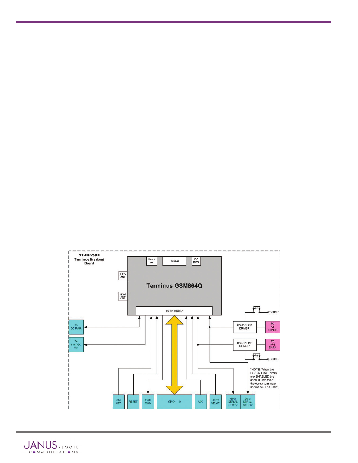
Jumpers – Jumpers P7 and P8 enable the RS-232 line drivers for the AT Command and GPS CMOS UART interface. If
the serial interface at the screw terminals is being used, these jumpers should NOT be used.
Jumper P7: Serial 1, AT Command – If communicating with the Terminus via the 50-PIN header CMOS UART
•
interface, the user will need to place a shunt across Jumper P7. This will enable the RS-232 line driver and allow
connection to a PC. If the 50-pin header CMOS UART is needed, the UART_SEL pin needs to be set to Logic “0”
or Ground.
If user is executing a Python script to control the application, the Python script should set GPIO 20 to logic zero
to send UART data out via the 50-PIN CMOS UART interface. The UART_SEL pin should not be externally driven
once GPIO 20 is configured as an output.
Jumper P8: Serial 2, GPS – To monitor the GPS NMEA data stream via the RS-232 line driver on connector P6
•
install this jumper.
© Copyright 2009 Janus Remote Communications All Rights Reserved Specifications subject to change without notice
Figure 1 - Terminus Break-out Board Block Diagram
Terminus Dev Kit Quick-Start Guide - GSM864Q Page 2 Rev: 00 Date: 01/12/09
Page 3

Connecting continued
Terminus Unit
Plug the Terminus unit onto the 50-pin header on the motherboard observing that the case is within the white outline
•
printed on the board. *Make sure mounting holes align with both the Terminal and the Breakout PCB.
Figure 2 - Terminus Break-out Board
Terminus Dev Kit Quick-Start Guide - GSM864Q Page 3 Rev: 00 Date: 01/12/09
© Copyright 2009 Janus Remote Communications All Rights Reserved Specifications subject to change without notice
Figure 3 - Terminus Break-out Board with Terminal Installed
Page 4

Connecting continued…
SIM Card
Insert SIM card into the SIM cardholder under the top cover on the Terminus as shown
•
Antennas
Connect the GSM antenna to the SMA jack on the Terminus.
•
Connect the GPS antenna to the MCX jack. Make sure that a clear sky view is available for best GPS reception.
•
Audio Devices
Connect the handset to the 4P4C modular audio jack on the Terminus
•
Power Supply
Plug power supply into power jack on the Terminus or apply +7 to +18 VDC to the P3 Terminal Block on the
•
Breakout Board
Plug the wall transformer into an appropriate 120VAC source
•
Terminus will power up as soon as voltage is applied. Also:
•
The GSM STATUS LED will begin to blink
•
The GPS DATA LED will begin to blink
•
GSM Computer Interface – This interface allows the user to communicate with the Telit Module.
Connect the 9-pin sub-D connector of serial cable to the DB9 connector P6 of the Breakout Board and plug
•
the other end into your computer’s serial port. Boot-up your computer. Bring up serial communications terminal
program and confirm your serial communications settings.
Serial Communications Settings:
Baud Rate = 115.2 kbps
•
Bits = 8
•
Stop Bits = 1
•
Parity = None
•
Hardware Handshaking = Yes
•
GPS Computer Interface – This interface allows the user to communicate with the CW20 GPS module.
Connect the 9-pin sub-D connector of serial cable to the DB9 connector PG of the Breakout Board and plug
•
the other end into your computer’s serial port. Boot-up your computer. Bring up serial communications terminal
program and confirm your serial communications settings.
Serial Communications Settings:
Baud Rate = 9600 bps
•
Bits = 8
•
Stop Bits = 1
•
Parity = None
•
Hardware Handshaking = Yes
•
NS3K View – This program has been included to allow the user to observe the GPS data graphically. Please refer
•
to the included Quick Start Guide to use.
Figure 4 - SIM Card Holder
© Copyright 2009 Janus Remote Communications All Rights Reserved Specifications subject to change without notice
Terminus Dev Kit Quick-Start Guide - GSM864Q Page 4 Rev: 00 Date: 01/12/09
Page 5

AT Commands
After the initial startup of the kit and a serial connection to a computer is made, refer to Section 6 of the Terminus
•
User Guide for the AT Commands needed to configure for network access.
Please refer to the Telit AT Commands Reference Guide document included on the Evaluation Kit CD for
•
command syntax and codes.
Additional Information
Please refer to the Terminus User Guide included on the Documentation CD for more detailed information on the
•
various capabilities and functions.
Please visit the Janus website at www.janus-rc.com for the latest product information and documentation.
•
Contents of the Terminus Evaluation Kit Companion CD
Terminus User Guide
•
Telit AT Commands Reference Guide
•
Telit GC864 Product Description
•
PyWin Python IDE
•
Telit Easy Script in Python
•
Telit Easy GPRS User Guide
•
Terminus Tracking Demo App Note
•
Terminus Tracking Demo Example Python Code
•
Terminus Dev Kit Quick-Start Guide - GSM864Q Page 5 Rev: 00 Date: 01/12/09
© Copyright 2009 Janus Remote Communications All Rights Reserved Specifications subject to change without notice
Page 6

Terminus GSM864Q
Development Kit Quick-Start Guide
Issue: R00
Revision Revision Date Note
R00 01/12/09 Release
Janus Remote Communications
Division of The Connor-Winfield Corporation
2111 Comprehensive Drive • Aurora, Illinois 60505
630.499.2121 • Fax: 630.851.5040
www.janus-rc.com
 Loading...