

Page 1
910CF Plug-In Modules
Evaluation Kit User Guide
Bulletin
Revision
Date
JA03-EKUM_910
A00
31 July 2013
Page 2
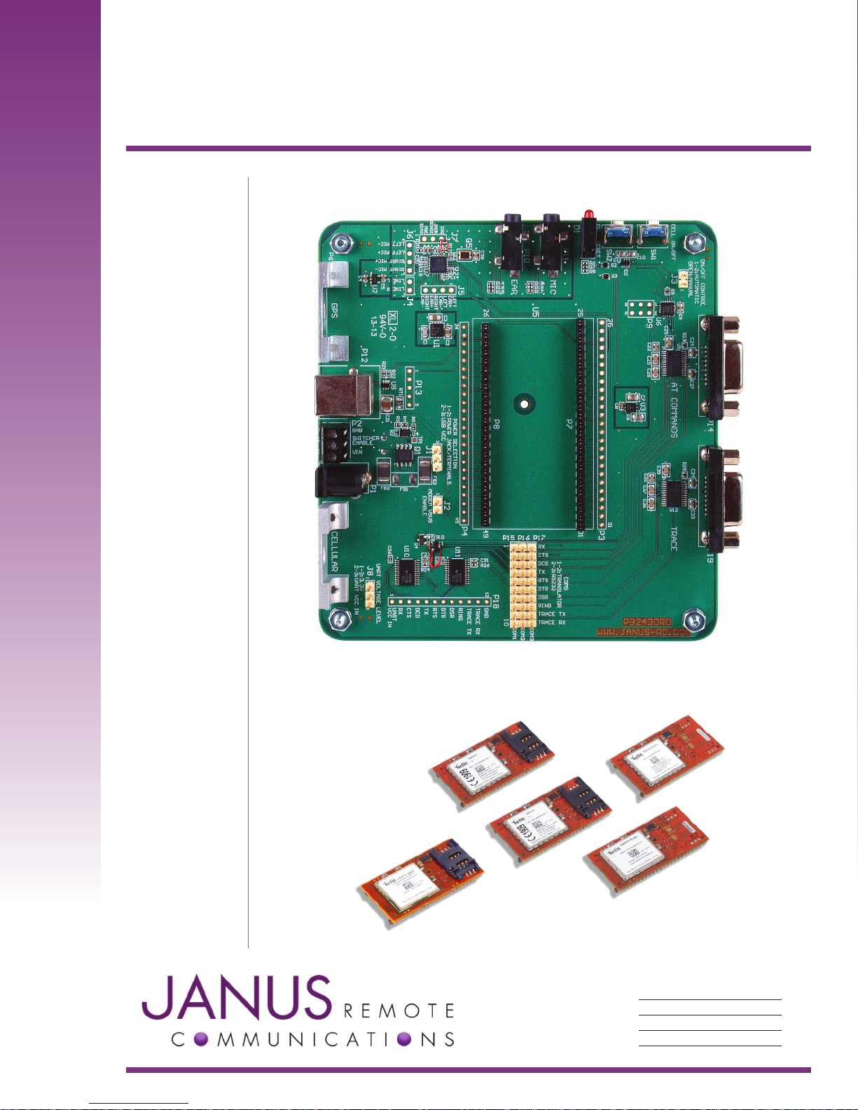
Introduction
The following document describes the functions of the evaluation board for the 910CF Plug-In series of
cellular communication terminals. This guide, along with the Plug-In Modules Hardware User guide, allows
all features of the terminal to be evaluated before your PCB goes into CAD.
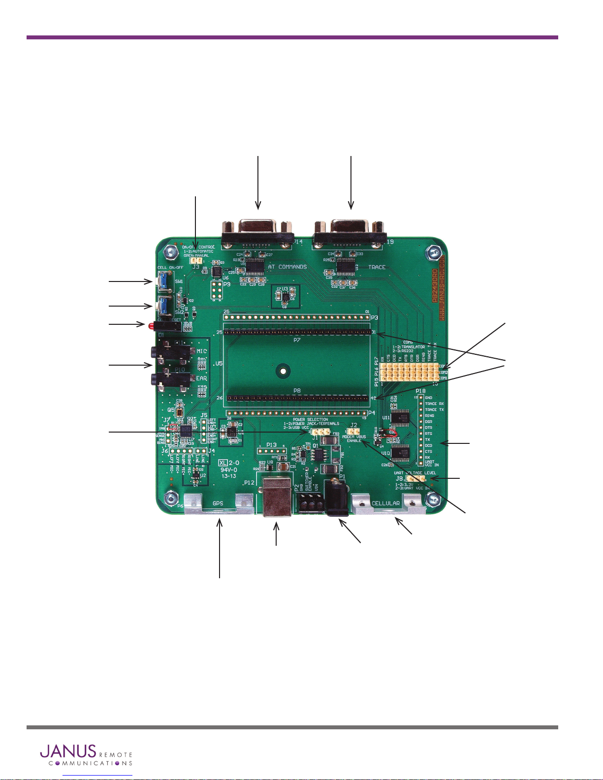
Evaluation Kit Board Details
AT Command
Port
Automatic
ON
Cellular
ON/OFF
Cellular
Reset
Status
LEDs
Telit Trace
Port
COM
Selection
Headers
3.1mm
Audio Jacks
Power
Selection
MCX Bracket
USB Port
Plug-In Module
Connector
UART Translation
Interface
UART VCC Select
VBUS Enable
SMA Bracket
Power IN
(2.1mm barrel connector)
Terminus 910CF Modules Evaluation Kit User Guide Page 2 Rev: A00 Date: 07/31/13
© Copyright 2013 Janus Remote Communications All Rights Reserved Specifications subject to change without notice
Page 3

Interfaces
Power Supply
The Evaluation Board requires 5VDC to power the evaluation PCB and module. The evaluation board
has two power supply connection options: center positive barrel connector or terminal block direct wire
connection.
The Evaluation Board is equipped with protection circuitry to prevent reverse voltage, as well as help
with protection from transients. The board can withstand a reverse voltage of -40V and a peak voltage of
60V. The circuitry is set to clip any input greater than 5.6V to a safe level.
Any input above 5.6V will read for a set period, and if before 2.0 uS has not returned to safe level, the
over-voltage protection will activate and turn off the output.
To re-enable the output, power must be cycled or the SWITCHER_EN pin (DIP pos. 7) must be pulled
low at least 3.0 μS and then released. Alternatively, if the power returns to a safe level for 36.0 mS the
output will re-enable.
Power supply requirement:
Voltage: 5Vdc ± 5%
Power: 10W peak
Serial Interfaces
RS-232 Serial Ports
The Evaluation board for the Plug-In terminals has two RS-232 serial ports.
AT COMMAND PORT:
This port is available to send AT commands to the terminal. Please refer to the CF Plug-In User Guide for serial
port details for the specific terminal you are evaluating.
Typical Port Settings:
Baud: 115200
Data bits: 8
Parity: None
Stop Bits: 1
Hardware Handshaking: CTS/RTS
Trace Port:
This port is used by the HSPA910CF terminal as a secondary serial AT interface. This port is not
used for Python script upload. However, during development of Python scripts this port can be used
to receive debug ‘print’ statements. In order to do this, AT#PORTCFG=3 should be used. Hardware
handshaking is not available on this port.
Port Settings:
Baud: 115200
Data bits: 8
Parity: None
Stop Bits: 1
Hardware Handshaking: N/A
Terminus 910CF Modules Evaluation Kit User Guide Page 3 Rev: A00 Date: 07/31/13
© Copyright 2013 Janus Remote Communications All Rights Reserved Specifications subject to change without notice
Page 4

Interfaces continued
Serial Interfaces continued…
UART Translator Interface:
If the user wants to communicate with the modem’s serial interface via the on board UART translation,
you can attach to the SIP header interface, P18. The full UART is broken out, along with TRACE TX and
TRACE RX.
The translator’s modem side level is referenced to VAUX, meaning it is OFF when the modem is off. This
function will tri-state the signals as recommended in the Plug in Modem User Manual.
The user can select between their own input voltage level and 3.3VDC by adjusting the J8 jumper setting.
1-2: 3.3V
2-3: User VCC In
If User VCC In is used, the header position #1, labeled UART VCC IN, should be connected to the desired
power supply.
Absolute Maximum Ratings
Parameters Min Max
Supply Voltage -0.5v 6.5v
Input Voltage -0.5v VCC + 0.5v
Continuous Output Current - +/- 50mA
Recommended Operating Characteristics
Parameter Supply Min Max
Supply Voltage 1.65v 5.5v
VIH 1.65v to 1.95v VCC*0.65 -
2.3v to 2.7v 1.7v -
3.0v to 3.6v 2.0v -
4.5v to 5.5v VCC*0.7 VIL 1.65v to 1.95v - VCC*0.35
2.3v to 2.7v - 0.7v
3.0v to 3.6v - 0.8v”
4.5v to 5.5v - VCC*0.3
VOH 1.65v to 1.95v 1.2v -
2.3v to 2.7v 1.9v -
3.0v to 3.6v 2.4v -
4.5v to 5.5v 3.8v VOL 1.65v to 1.95v - 0.45v
2.3v to 2.7v - 0.3v
3.0v to 3.6v - 0.55v
4.5v to 5.5v - 0.55v
Terminus 910CF Modules Evaluation Kit User Guide Page 4 Rev: A00 Date: 07/31/13
© Copyright 2013 Janus Remote Communications All Rights Reserved Specifications subject to change without notice
Page 5
Interfaces continued
Serial Interfaces continued…
USB Serial Ports:
The development board allows access to virtual COM ports and modem ports via the USB. To use this
interface during development you will need to download the USB drivers from the Janus website (www.
janus-rc.com).
The HSPA910CF will show several virtual COM ports after the drivers are installed. These are USB0
through USB6, along with a modem for applications like Dial Up with Windows. This allows for
applications like simultaneous AT commands, voice calls, and Python tracing.
These ports can be configured in various ways depending on the user’s application, but by default
USB0 and USB3 are AT command ready after enumeration.
Typical Port Settings:
Baud: 115200
Data bits: 8
Parity: None
Stop Bits: 1
Hardware Handshaking: N/A
You will want to reference the HSPA910CF Ports Arrangements application note for full details on using
the AT#PORTCFG command.
Please note that in order for proper power on sequencing, the modem must be turned on first. The
USB VCC line must be disconnected until the device is on otherwise it may not power up correctly, or
properly install the USB drivers. The development board already handles this power sequencing for you
in both automatic turn on and manual turn on modes, but it is good to note for your implementation
outside of the development kit.
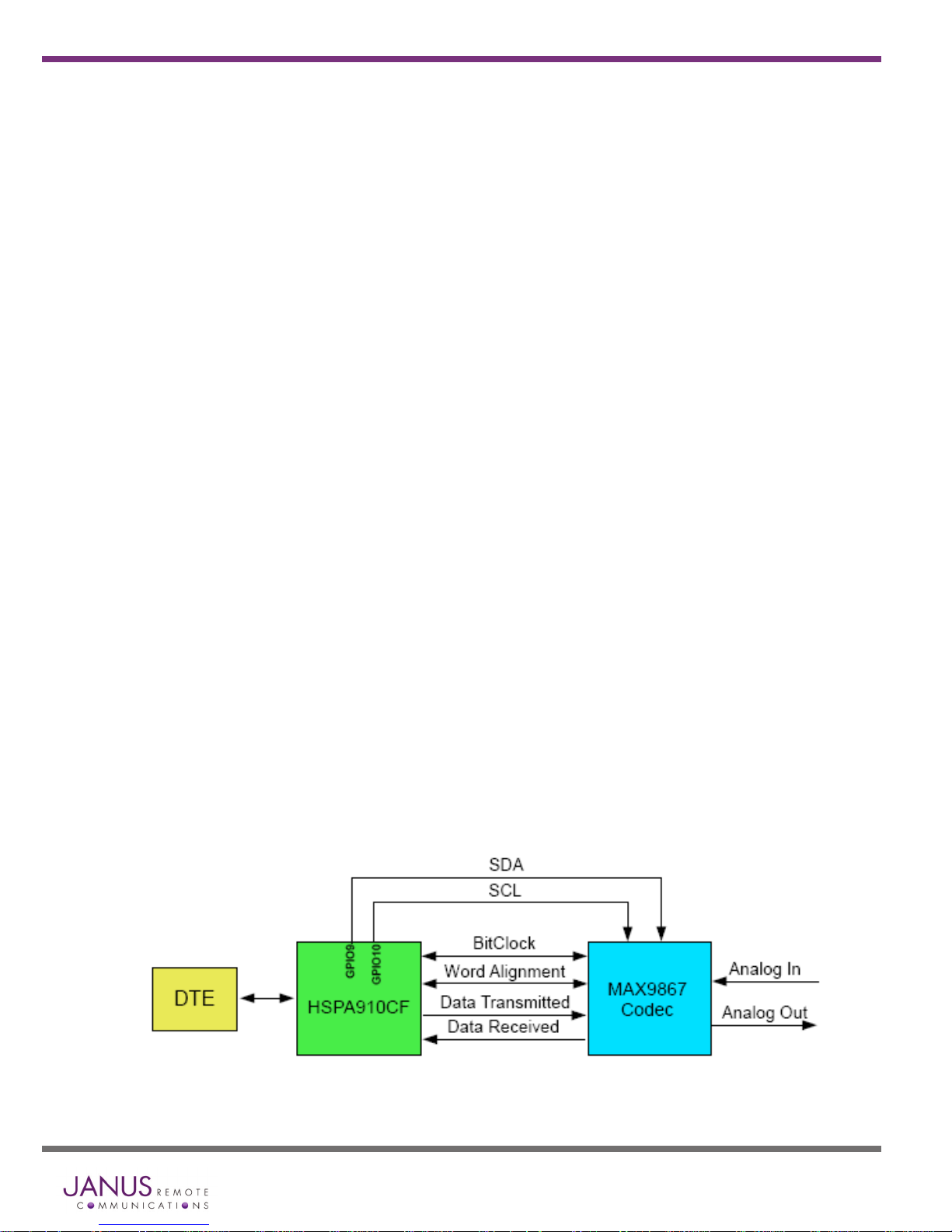
Audio
The development board is equipped to take advantage of the DVI signals present on the HSPA910CF
and EVDO910CF. The connection available to the user is in separate 3.5mm EAR and MIC ports. The
audio uses the MAX9867 IC and is set for capacitorless differential mode. Control of the MAX IC is
done via the I2C available on the modems (using GPIO 9 and GPIO 10) with the AT#I2CWR command.
Terminus 910CF Modules Evaluation Kit User Guide Page 5 Rev: A00 Date: 07/31/13
© Copyright 2013 Janus Remote Communications All Rights Reserved Specifications subject to change without notice
Page 6

Push Button Switches
The development board has 2 push buttons to control the state of the Plug in Modem.
Cell ON/OFF
This switch is used to toggle the modem ON or OFF. When the board is set to manual control, this signal
must be used to turn the modem ON by holding the switch for 5 seconds and then releasing.
Cell RESET
This switch is used to recover operation of the Plug in Terminal in case of unexpected error resulting from
the inability of the application to communicate with the terminal.
LED Indicators
The board is equipped with an LED stack with Red, Yellow, and Green LEDs.
Green – Connected to the modem’s GPIO #2, adjusted with the AT#GPIO command
Green LED Status Device Status
Permanently Off GPIO is LOW
Permanently On GPIO is HIGH
Yellow – Connected to the modem’s GPIO #1, which doubles as the cell status indication.
Yellow LED Status Device Status
Permanently Off Cellular radio is off
Permanently On On/Searching
Slow Blinking (0.3 sec on / 2.7 sec off) Registered
Fast Blinking (0.5 sec on / 0.5 sec off) Shutting down
Red – This LED is an indicator to show the status of VBUS, which indicates if the USB connection is active.
Red LED Status Device Status
Permanently Off VBUS is LOW
Permanently On VBUS is HIGH
RF Interfaces
There are two brackets for the RF connections to the antenna. The board itself does not have an RF
interface; instead it allows the user to run mini coax cables to hard points for antenna access.
CELLULAR –
This bracket is for an SMA ended cable, in our evaluation kit we include a Murata GSC to SMA connector for this
purpose.
GPS –
This bracket is for an MCX ended cable, in our evaluation kit we include a Murata GSC to MCX connector for this
purpose.
Terminus 910CF Modules Evaluation Kit User Guide Page 6 Rev: A00 Date: 07/31/13
© Copyright 2013 Janus Remote Communications All Rights Reserved Specifications subject to change without notice
Page 7

Development Board Jumpers and Headers
There are several jumpers available on the board to allow maximum flexibility.
J1 Power Selection:
1-2: Power Jack/Terminals
2-3: USB VCC
This jumper controls what the board itself will be powered from, allowing the user to do power analysis
of the Plug in Modem by itself in regard to the main power input.
If the USB configuration is used, please note that only the evaluation board and a majority of its
components will be powered by the USB. The attached CF module and evaluation board protection
circuitry will not be and will still need to draw its power from the main “Power In” screw terminals or barrel
jack. The protection circuitry will add a draw of roughly 1.0mA.
J2 Modem VBUS Enable
1-2: Enabled
Open: Disabled
This jumper controls if the VBUS signal can be attached to the Plug in Modem. This ONLY controls
the VBUS signal to the Plug in Modem; this jumper has no effect on powering the development board
from the USB connection.
J8 UART Voltage Level
1-2: 3.3V
2-3: User VCC In
This jumper controls what voltage reference is used for the on board UART translation. The user can
select between a specific desired input voltage level and 3.3VDC.
If User VCC In is used, the header position #1, labeled UART VCC IN, should be connected to the desired
power supply.
J3 ON/OFF CONTROL
1-2: Automatic
Open: Manual
This jumper controls if the board will automatically turn on the Plug in Modem. The on board
microcontroller will handle the power sequencing regardless of the selection; this simply allows the
user to utilize the CELL ON/OFF switch to turn the unit on or off.
P15, P16, P17 COMS Header Rows
1-2: Translator
2-3: RS232
This header section is for choosing which section of the board to communicate to the modem through.
Terminus 910CF Modules Evaluation Kit User Guide Page 7 Rev: A00 Date: 07/31/13
© Copyright 2013 Janus Remote Communications All Rights Reserved Specifications subject to change without notice
Page 8

Getting Started
This will take you through the initial steps required that will allow AT commands to be sent to the Plug in
module.
USB Communications
Step 1
Please confirm that you have these items:
Power supply with 2.1mm barrel connector termination
3’ USB cable
Murata GSC to SMA cable
Murata GSC to MCX cable (Optional)
Cellular Antenna
GPS Antenna (Optional)
Jumper Shunts
Step 2
Use the jumpers to set the following for basic configuration:
J1 Power Selection – 1-2 (Power Jack)
J2 Modem VBUS Enable – 1-2 (Enabled)
J3 ON/OFF Control – 1-2 (Automatic)
No other jumpers are required for this, and may be left off.
Step 3
If not done already, plug the HSPA910CF Plug in Module into the connectors at the center of the Development
Board, being sure to align the pins properly. Take note that to make the alignment easier, the two connectors are
of different lengths.
Step 4
Cellular: Use the included GSC to SMA cable and attach the GSC end to P5 (CELL) on the HSPA910CF and the
other end to the CELL bracket. Then attach the cellular antenna to the SMA connector.
GPS: Use the included GSC to MCX cable and attach the GSC end to P6 (GPS) on the HSPA910CF and the
other end to the GPS bracket. Then attach the GPS antenna to the MCX connector, giving the antenna ample
view of the sky
Step 5
Connect the USB cable to the USB B connector on the board; connect the other end to an available USB port
on your PC.
Step 6
Plug in your power supply to the 2.1mm barrel connector on the board, labeled P1. The auto-start will turn the
unit on and you should see the Yellow LED begin blinking after roughly 5 seconds. The USB connection will then
activate after another 5 seconds, with an indication by the Red LED.
Terminus 910CF Modules Evaluation Kit User Guide Page 8 Rev: A00 Date: 07/31/13
© Copyright 2013 Janus Remote Communications All Rights Reserved Specifications subject to change without notice
Page 9

Getting Started continued
USB Communications continued
Step 7
You should see the following ports in the Windows Device
manager:
USB1
USB2
USB3
USB4
USB5
USB6
If these do not become available, or you see an error
message, this means you need to install the USB drivers for
the HSPA910CF. Please refer to http://www.janus-rc.com/
terminuscf.html for the proper drivers before continuing.
Step 8
Open HyperTerminal or a similar terminal emulator and start
a new session. Use the drop down box to select the COM
port that corresponds to the USB3 connection.
Then select “Configure,” and select these settings:
Bits per second: 115200
Data Bits: 8
Parity: None
Stop Bits: 1
Flow control: None
Then press “OK.”
Step 9
Click on the “Call” button in HyperTerminal to make the
connection. In the window you should now be able to
send AT commands. To make sure you have a proper
connection, type “AT” into the window, and press Enter.
You should receive a response of “OK”.
If you do not receive that response, go back and check to make sure you’ve selected the correct COM port, as
well as the settings.
If you receive an OK, your connection is successful and you are now able to communicate with the module.
Please refer to http://www.janus-rc.com/terminuscf.html for a link to further documentation.
The CF User Manual will give you step by step instructions on setting up voice and data calls, SMS messages,
and socket connections. These functions are basic and easily done, but are out of the scope of this document as
the steps may differ slightly between modem types.
Terminus 910CF Modules Evaluation Kit User Guide Page 9 Rev: A00 Date: 07/31/13
© Copyright 2013 Janus Remote Communications All Rights Reserved Specifications subject to change without notice
Page 10

Getting Started continued
RS232 Serial Communication
Step 1
Please confirm that you have these items:
Power supply with 2.1mm barrel connector termination
6’ RS232 cable
Murata GSC to SMA cable
Murata GSC to MCX cable (Optional)
Cellular Antenna
GPS Antenna (Optional)
Jumper Shunts
Step 2
Use the jumpers to set the following for basic configuration:
J1 Power Selection – 1-2 (Power Jack)
J3 ON/OFF Control – 1-2 (Automatic)
P15, P16, P17 COMS – 2-3 (RS-232)
No other jumpers are required for this, and may be left off.
Step 3
If not done already, plug the HSPA910CF Plug in Module into the connectors at the center of the Development
Board, being sure to align the pins properly. Take note that to make the alignment easier, the two connectors are
of different lengths.
Step 4
Cellular: Use the included GSC to SMA cable and attach the GSC end to P5 (CELL) on the HSPA910CF and the
other end to the CELL bracket. Then attach the cellular antenna to the SMA connector.
GPS: Use the included GSC to MCX cable and attach the GSC end to P6 (GPS) on the HSPA910CF and the other end
to the GPS bracket. Then attach the GPS antenna to the MCX connector, giving the antenna ample view of the sky
Step 5
Connect the RS-232 cable to the AT COMMANDS DB9 connector on the board; connect the other end to an
available serial port on your PC.
Step 6
Plug in your power supply to the 2.1mm barrel connector on the
board, labeled P1. The auto-start will turn the unit on and you
should see the Yellow LED begin blinking after roughly 5 seconds.
Step 7
Open HyperTerminal or a similar terminal emulator and start a
new session. Use the drop down box to select the COM port
that corresponds to the serial port connection.
Then select “Configure,” and select these settings:
Bits per second: 115200
Data Bits: 8
Parity: None
Stop Bits: 1
Flow control: Hardware
Then press “OK.”
Terminus 910CF Modules Evaluation Kit User Guide Page 10 Rev: A00 Date: 07/31/13
© Copyright 2013 Janus Remote Communications All Rights Reserved Specifications subject to change without notice
Page 11

Getting Started continued
RS232 Serial Communication continued
Step 8
Click on the “Call” button in HyperTerminal to make the connection. In the window you should now be able to
send AT commands. To make sure you have a proper connection, type “AT” into the window, and press Enter. You
should receive a response of “OK”.
If you do not receive that response, go back and check to make sure you’ve selected the correct COM port, as well
as the settings.
If you receive an OK, your connection is successful and you are now able to communicate with the module.
Please refer to http://www.janus-rc.com/terminuscf.html for a link to further documentation.
The CF User Manual will give you step by step instructions on setting up voice and data calls, SMS messages,
and socket connections. These functions are basic and easily done, but are out of the scope of this document as
the steps may differ slightly between modem types.
Audio
The audio connection can be utilized by any of the Plug in Modules that have a DVI interface. This section
assumes that AT communication to the modem has been achieved.
HSPA910CF
• Enable the DVI interface and set it to master mode
AT#DVI=1,2,1
• Set the interface type, and sample information.
AT#DVIEXT=1,0,0,1,0
• Set the handset microphone gain.
AT#HSMICG=2
• Disable the handset sidetone.
AT#SHSSD=0
• Write the MAX9867 register information.
AT#I2CWR=9,10,30,4,19
Wait for response ”>” then enter the register information
>00109000100A330000330C0C09092424400060
Press CTRL+z to send the information
Wait for response “OK”
AT#I2CWR=9,10,30,17,1
Wait for response ”>” then enter the register information
>8A
Press CTRL+z to send the information
Wait for response “OK”
• Test the audio output by using a test tone generation.
AT#TONE=5,10
This will send out the DTMF tone for the #5 key press, for 1 second.
If the tone can be heard, the audio path has been set up and can now be utilized for voice calls or other purposes.
If the audio cannot be heard or is very quiet, the TSVOL command can be utilized to bring up the volume.
Example
AT#TSVOL=255,1,10
This adjusts all audio types, and a max value of 14 can be used. Please see the AT Command Reference for full command
details.
Terminus 910CF Modules Evaluation Kit User Guide Page 11 Rev: A00 Date: 07/31/13
© Copyright 2013 Janus Remote Communications All Rights Reserved Specifications subject to change without notice
Page 12

Getting Started continued
EVDO910CF
• Enable the DVI interface and set it to master mode.
AT#DVI=1,2,1
• Set the interface type, and sample information.
AT#DVICFG=1,1,2,1,2
• Set the handset microphone gain.
AT#HSMICG=2
• Disable the handset sidetone.
AT#SHSSD=0
• Write the MAX9867 register information.
With the EVDO910CF, we can’t use the I2CWR command fully due to a current issue with multi-byte writing.
Example
AT#I2CWR=9,10,30,5,18 <-- This will return “OK”, but won’t actually work
Instead, we have to use it in single byte format if we want to use I2CWR, like below
Example
AT#I2CWR=9,10,30,5,1
Wait for response ”>” then enter the register information
>10
Press CTRL+z to send the information
Wait for response “OK”
The full flow of commands is as follows:
AT#I2CWR=9,10,30,5,1
>10
AT#I2CWR=9,10,30,6,1
>10
AT#I2CWR=9,10,30,7,1
>00
AT#I2CWR=9,10,30,8,1
>74
AT#I2CWR=9,10,30,9,1
>0A
AT#I2CWR=9,10,30,A,1
>00
AT#I2CWR=9,10,30,B,1
>00
AT#I2CWR=9,10,30,C,1
>00
AT#I2CWR=9,10,30,D,1
>33
AT#I2CWR=9,10,30,F,1
>0C
AT#I2CWR=9,10,30,10,1
>09
AT#I2CWR=9,10,30,11,1
>09
AT#I2CWR=9,10,30,12,1
>24
AT#I2CWR=9,10,30,13,1
>24
AT#I2CWR=9,10,30,14,1
>40
AT#I2CWR=9,10,30,15,1
>00
AT#I2CWR=9,10,30,16,1
>60
AT#I2CWR=9,10,30,17,1
>8A
AT#I2CWR=9,10,30,E,1
>0C
• Test the audio output by using a test tone generation.
AT#TONE=5,10
This will send out the DTMF tone for the #5 key press, for 1 second.
If the tone can be heard, the audio path has been set up and can now be utilized for voice calls or other purposes.
If the audio cannot be heard or is very quiet, the TSVOL command can be utilized to bring up the volume.
Example
AT#TSVOL=255,1,10
This adjusts all audio types, and a max value of 14 can be used. Please see the AT Command Reference for full command details.
Terminus 910CF Modules Evaluation Kit User Guide Page 12 Rev: A00 Date: 07/31/13
© Copyright 2013 Janus Remote Communications All Rights Reserved Specifications subject to change without notice
Page 13

Errata
The following points are noted issues with the current build of the 910 Evaluation PCB. The board has been tested as
working with these changes, but Janus Remote Communications offers no warranty.
Point 1:
I2C lines to the codec, routed manually
Point 2:
Adjustment of a FET array for proper VBUS control.
Point 2
Point 2
Terminus 910CF Modules Evaluation Kit User Guide Page 13 Rev: A00 Date: 07/31/13
© Copyright 2013 Janus Remote Communications All Rights Reserved Specifications subject to change without notice
Page 14

Plug-In Modules
Evaluation Kit User Guide
Revision Revision Date Note
A00 07/31/13 Preliminary Release
Division of The Connor-Winfield Corporation
2111 Comprehensive Drive • Aurora, Illinois 60505
630.499.2121 • Fax: 630.851.5040
www.janus-rc.com
Janus Remote Communications Europe
Bay 143
Shannon Industrial Estate
Shannon, Co. Clare, Ireland
Phone: +353 61 475 666
 Loading...