

Page 1
Doc. no. 1.040.137.1.f 01/2018
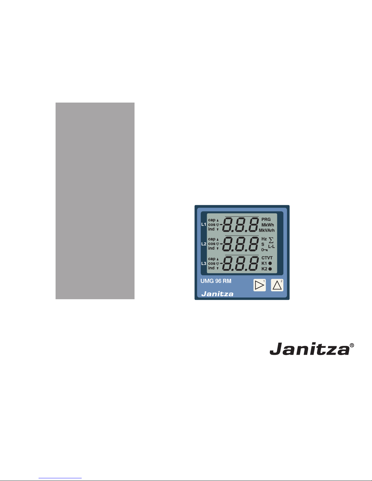
Power Analyser
UMG 96 RM-PN
User manual and
technical data
Part no. 33.03.202
Janitza electronics GmbH
Vor dem Polstück 6
D-35633 Lahnau
Support tel. +49 6441 9642-22
Fax +49 6441 9642-30
E-mail: info@janitza.com
www.janitza.com
www.janitza.com
Power Analyser
Page 2

2
UMG 96RM-PN
Table of contents
General information 4
Inspection on receipt 6
Available accessories 7
Product description 8
Proper use 8
UMG 96RM-PN features 10
Measuring process 11
Operating concept 11
GridVis network analysis software 11
Connection variants 12
Assembly 13
Installation 15
Supply voltage 15
Voltage measurement 16
Current measurement using I1 to I4 22
Analogue inputs 30
Residual current monitoring (RCM) via I5, I6 31
Thermistor input 33
RS485 interface 34
Ethernet / ProfiNet interface 37
Digital in-/outputs 39
LED status bar 44
Operation 45
Display mode 45
Programming mode 45
Parameters and measured values 47
Configuration 49
Connecting the supply voltage 49
Current and voltage transformer 49
Programming the current transformer for I1-I3 51
Programming the voltage transformer 52
Programming parameters 53
TCP/IP configuration 54
RS485 device address (addr. 000) 56
RS485 baud rate (addr. 001) 56
User password (addr. 050) 57
Parameters 58
Mean value 58
Averaging method 58
Min. and max. values 58
Mains frequency (addr. 034) 59
Power meters 60
Resetting energy meters (addr. 507) 60
Harmonics 61
Measured value rotation 62
Measured value screens 62
Direction of the rotating field 64
LCD contrast (addr. 035) 64
Backlight 64
Time logging 66
Operating hours counter 66
Total running time, comparator 66
Page 3

3
UMG 96RM-PN
Serial number (addr. 754) 67
Software release (addr. 750) 67
Commissioning 68
Connecting the supply voltage 68
Connecting the measured voltage 68
Applying the measuring-circuit voltage 68
Direction of the rotating field 69
Checking the phase assignment 69
Checking the power measurement 69
Applying the residual current 69
Failure monitoring (RCM) for I5, I6 70
Checking the measurement 71
Checking the single phase powers 71
Checking the sum powers 71
RS485 interface 72
Digital outputs 74
Digital output status indicators 75
Pulse output (Group 1) 77
Comparators and threshold value monitoring 82
Service and maintenance 88
Service 88
Device calibration 88
Calibration intervals 88
Firmware update 89
Error / warning messages 90
Technical data 96
Function parameters 103
Table 1 - Parameter list 105
Table 2 - Modbus address list 112
Number formats 115
Dimension diagrams 116
Measured value screen overview 118
Connection example 1 124
Connection example 2 125
Basic functions quick guide 126
TCP/IP addressing quick guide 127
Page 4

4
UMG 96RM-PN
Comments on the manual
We welcome your comments. If anything in this manual
seems unclear, please let us know by sending an e-mail
to: info@janitza.de
Meaning of symbols
This manual uses the following pictograms:
General information
Copyright
This manual is subject to the statutory provisions
of copyright law and may not be photocopied, reprinted,
or reproduced - in whole or in part, by mechanical
or electronic means - nor otherwise duplicated or
republished, without the binding written permission of:
Janitza electronics GmbH, Vor dem Polstück 1,
D 35633 Lahnau, Germany
Trademarks
All trademarks and the resulting rights are the property
of their respective owners.
Disclaimer
Janitza electronics GmbH accepts no responsibility for
errors or deficiencies within this manual, and makes
no commitment to keep the contents of this functional
description up to date.
c
Dangerous voltage!
Risk to life or serious injury. Before
commencing work on the system and
the device, they must first be de-energised.
m
Attention!
Please pay attention to the documentation.
This symbol is intended to warn you of
potential dangers, which could occur during
installation, commissioning and use.
C
Note!
Page 5

5
UMG 96RM-PN
Instructions on use
Please read this operation manual as well as all other
publications that must be consulted for working with this
product (in particular, for the installation, operation or
maintenance).
Observe all safety instructions and warnings. Failure
to comply with the instructions can result in personal
injuries and/or damage to the product.
Any unauthorised changes or use of this device, which
go beyond the mechanical, electrical or otherwise stated
operating limitations, can result in bodily injury or/and
damage to the product.
Any such unauthorised change constitutes "misuse"
and/or "negligence" according to the warranty for
the product and thus excludes the warranty for covering
possible damage resulting from this.
This device must only be operated and repaired by
specialised personnel.
Specialised personnel are persons, that based on
their respective training and experience, are qualified
to recognise risks and prevent potential dangers that
c
If the device is not operated according
to the operation manual, protection is
no longer ensured and hazards can be
presented by the device.
m
Single core conductor must be provided
with core end sheath.
m
Only pluggable screw terminals with the same
number of poles and the same type of construction
are permitted to be connected together.
can be caused by the operation or maintenance of
the device.
Additional legal and safety regulations required for
the respective application are to be followed during
the use of the device.
Page 6

6
UMG 96RM-PN
Inspection on receipt
The prerequisites of faultless, safe operation of this
device are proper transport and proper storage, setup and installation, as well as careful operation and
maintenance. If it can be assumed that risk-free
operation is no longer possible, the device must be
immediately put out of operation and secured against
being put back into operation again.
Packing and unpacking must be carried out with
customary care without the use of force and only using
suitable tools. The devices should be visually checked
for flawless mechanical condition.
It can be assumed that risk-free operation is no longer
possible if the device, for example,
• has visible damage,
• no longer works despite the mains power supply
being intact,
• has been exposed to prolonged adverse conditions
(e.g. storage outside the permissible climate
limits without being adapted to the room climate,
condensation, etc.) or rough handling during
transportation (e.g. falling from a height, even if there
is no visible external damage, etc.).
• Please check the delivered items for completeness
before you start installing the device.
C
All screw-type terminals included in
the scope of delivery are attached to
the device.
Concerning this operation manual
This operation manual is part of the product.
• Read the operation manual before using the device.
• Keep the operation manual instructions throughout
the entire service life of the product and have them
readily available for reference.
• Pass the operation manual on to each subsequent
owner or user of the product.
Page 7

7
UMG 96RM-PN
Number Part no. Designation
2 52.22.251 Mounting clips
1 10.01.855 Screw-type terminal, pluggable, 2-pole (auxiliary power)
1 10.01.849 Screw-type terminal, pluggable, 4-pole (voltage measurement)
1 10.01.871 Screw-type terminal, pluggable, 6-pole (current measurement I1-I3)
1 10.01.875 Screw-type terminal, pluggable, 2-pole (current measurement I4)
1 10.01.865 Screw-type terminal, pluggable, 10-pole (digital/analogue inputs/outputs)
1 10.01.857 Screw-type terminal, pluggable, 2-pole (RS 485)
1 10.01.859 Screw-type terminal, pluggable, 3-pole (digital/pulse output)
1 08.01.505 Patch cable 2 m, twisted, grey (connection UMG 96RM-PC/switch)
1 52.00.008 RS485 termination resistor, 120 ohms
1 29.01.065 Silicone seal, 96 x 96
1 15.06.015 Interface converter RS485 <-> RS232
1 15.06.025 Interface converter RS485 <-> USB
Available accessories
Page 8

8
UMG 96RM-PN
Product description
Proper use
The UMG 96RM-PN is intended for the measurement
and calculation of electrical variables such as voltage,
current, power, energy, harmonics, etc. in building
installations, on distribution units, circuit breakers and
busbar trunking systems.
The UMG 96RM-PN is suitable for integration into fixed
and weatherproof switch panels. Conductive switch
panels must be earthed.
Measured voltages and measured currents must derive
from the same network.
The measurement results can be displayed and read
out and further processed via the RS485 or ProfiNet
interface.
The voltage measurement inputs are designed for
measurements in low voltage networks where rated
voltages of up to 300V phase to earth and surge voltages
of overvoltage category III can occur.
The current measurement inputs I1-I4 of the UMG
96RM-PN are connected via external ../1A or ../5A
current transformers.
A continuous monitoring of residual currents (residual
current monitor, RCM) is performed via the current
measurement inputs I5 and I6 via an external residual
current transformer with a rated current of 30 mA.
Measurements in medium and high-voltage networks are
always performed via current and voltage transformers.
m
Residual current monitoring monitors residual
currents via external current transformers.
The device is not an independent protective
device!
Page 9

9
UMG 96RM-PN
Device parameters
• Supply voltage:
Option 230V: 90V - 277V (50/60Hz) or
DC 90V - 250V; 300V CATIII
Option 24V: 24 - 90V AC / DC; 150V CATIII
• Frequency range: 45 - 65 Hz
Device functions
• 3 voltage measurement channels, 300V
• 4 current measurements
(via current transformer ../5A or ../1A)
• 2 residual current measurements
(via residual current transformer ../30mA) or
optionally 2 temperature measurements
• RS485 interface, ethernet and ProfiNet
• 2 digital outputs and additionally 3 digital inputs/
outputs
Page 10

10
UMG 96RM-PN
UMG 96RM-PN features
General information
• Front panel integration device with dimensions
96x96 mm
• Connection via pluggable screw terminals
• LC display with backlight
• Operation via 2 buttons
• 3 Voltage and 4 current measurement inputs
• Either 2 residual current or temperature
measurement inputs
• 2 digital outputs and 3 digital inputs/outputs
• RS485 interface (Modbus RTU, slave, up to 115
kbps)
• 2 interfaces for ethernet / ProfiNet
• Working temperature range -10°C to +55°C
Measurement uncertainty
• Effective energy, measurement uncertainty class
0.5 for ../5A converter
• Effective energy, measurement uncertainty class 1
for ../1A converter
• Reactive energy, class 2
Measurement
• Measurement in IT, TN and TT networks
• Measurement in networks with rated voltages up
to L-L 480V and L-N 277V
• Measurement range current 0 to 5A eff.
• True RMS (TRMS)
• Continuous sampling of the voltage and current
measurement inputs
• Continuous monitoring of residual currents
with failure monitoring
• Temperature measurement
• Frequency range of the fundamental oscillation 45
Hz to 65 Hz
• Measurement of the 1st to 40th harmonics, for ULN
and I1-I3
• Uln, I, P (cons./del.), Q (ind./cap.)
• Capturing substantially more than 1000 measured
values
• Fourier analysis 1st to 40th harmonics for U and
I1-I3
• 7 power meters for
Effective energy (cons.), Effective energy (delivery),
Effective energy (without backstop),
Reactive energy (in 4 quadrants: delivered, consumed,
in each case ind./cap.),
Reactive energy (without backstop), Apparent energy,
for each of L1, L2, L3 and sum
Page 11

11
UMG 96RM-PN
Measuring process
The UMG 96RM-PN measures continuously and
calculates all effective values over a 10/12 period
interval. The device measures the real effective value
(TRMS) of the voltages and currents connected to
the measurement inputs.
Operating concept
You can program and call up the measured values via
many routes using the UMG 96RM-PN.
• Directly on the device via 2 buttons.
• Using the GridVis programming software.
• Using the device homepage (no programming).
• Using the Modbus protocol.
You can modify and call up the data using
the Modbus address list. The list can be called up
via the device's home page and can be found on
the enclosed CD.
• Using the PLC within a PROFINET environment.
This operation manual only describes how to operate
the UMG 96RM-PN using the two buttons.
The GridVis programming software has its own "online
help" system.
GridVis network analysis software
The UMG 96RM-PN can be programmed and read out
using the GridVis network analysis software (Download:
www.janitza.com). For this, a PC must be connected to
the UMG 96RM-PN via a serial interface (RS485) or by
ethernet.
GridVis features
• Programming the UMG 96RM-PN
• Graphical representation of measured values
Page 12
12
UMG 96RM-PN
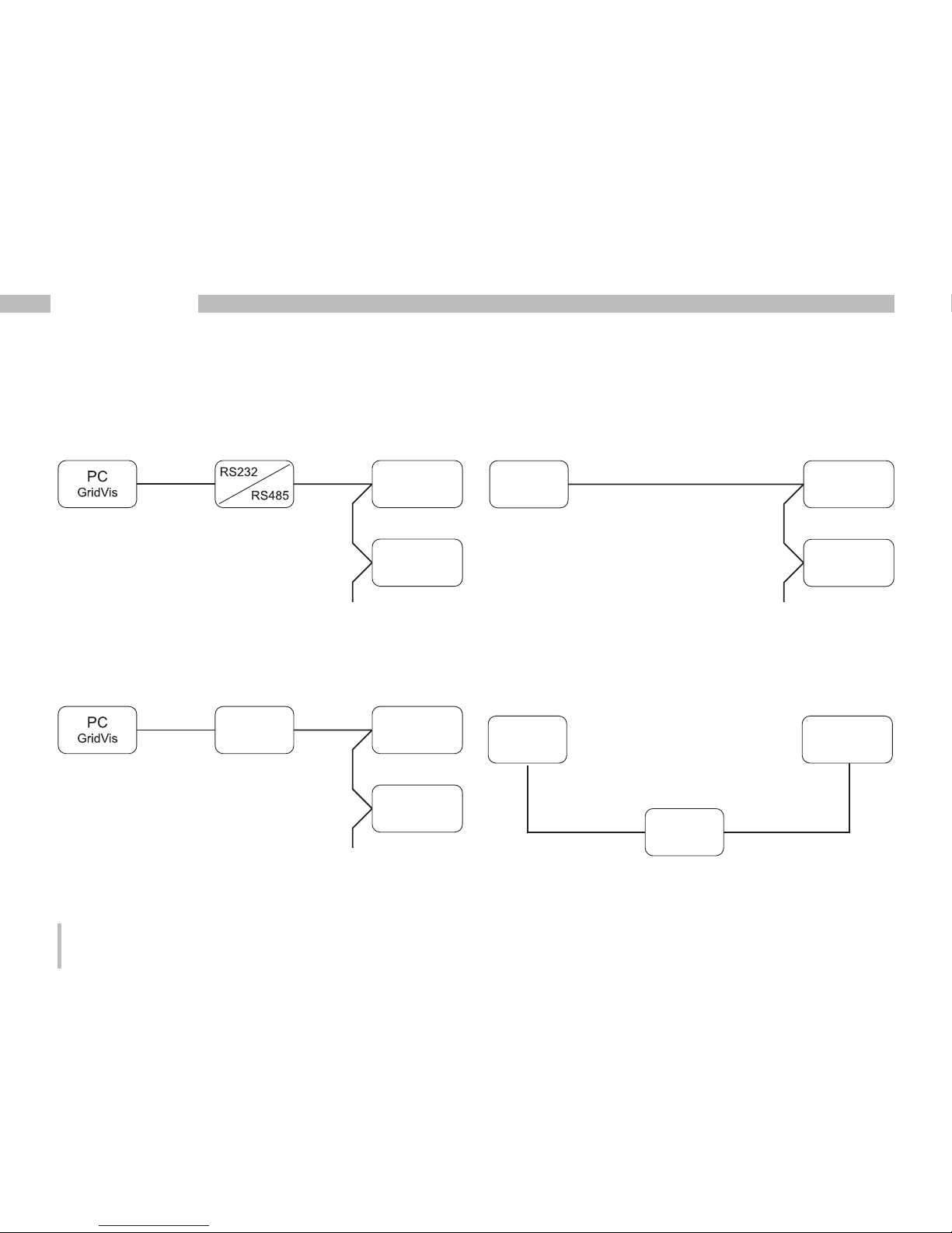
Connection variants
Connection of a UMG 96RM-PN to a PC via an interface
converter:
Connection of a UMG 96RM-PN via an UMG 604 as
a gateway.
Direct connection of a UMG 96RM-PN to a PC/PLC via
Ethernet/ProfiNet.
Ethernet / ProfiNet
Ethernet / ProfiNet
RS485
RS485
PC (GridVis)
SPS
UMG 96RM-PN
UMG 96RM-PN
Ethernet / ProfiNet
Ethernet / ProfiNet
RS485
RS485
RS485
RS485
Ethernet
Ethernet / ProfiNet
Ethernet / ProfiNet
PC (GridVis)
SPS
UMG 96RM-PN
UMG 96RM-PN
UMG 604
Connection of a UMG 96RM-PN to a PC/PLC via
Ethernet/ProfiNet.
Ethernet / ProfiNet
Ethernet / ProfiNet
Ethernet / ProfiNet
Ethernet / ProfiNet
Ethernet / ProfiNet
RS485
RS485
RS485
RS485
Ethernet
Ethernet / ProfiNet
Ethernet / ProfiNet
PC (GridVis)
SPS
PC
(GridVis)
SPS
UMG 96RM-PN
Switch
Ethernet / ProfiNet
Ethernet / ProfiNet
PC (GridVis)
SPS
UMG 96RM-PN
UMG 96RM-PN
Page 13
13
UMG 96RM-PN
Assembly
Position of installation
The UMG 96RM-PN is suitable for integration into fixed
and weatherproof switch panels. Conductive switch
panels must be earthed.
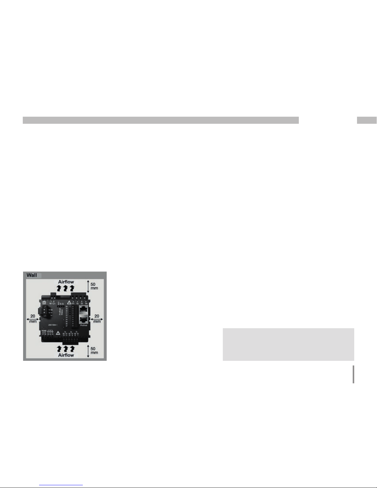
Mounting position
To ensure adequate ventilation, the UMG 96RM-PN
must be installed vertically. There should be separation
above and below of at least 50mm with 20mm space to
the sides.
Front panel section
Cut-out size:
92
+0.8
x 92
+0.8
mm.
m
Failure to meet the minimum clearances
can destroy the UMG 96RM-PN at high
ambient temperatures!
Fig. Mounting position
UMG 96RM-PN
(View from rear)
Page 14
14
UMG 96RM-PN
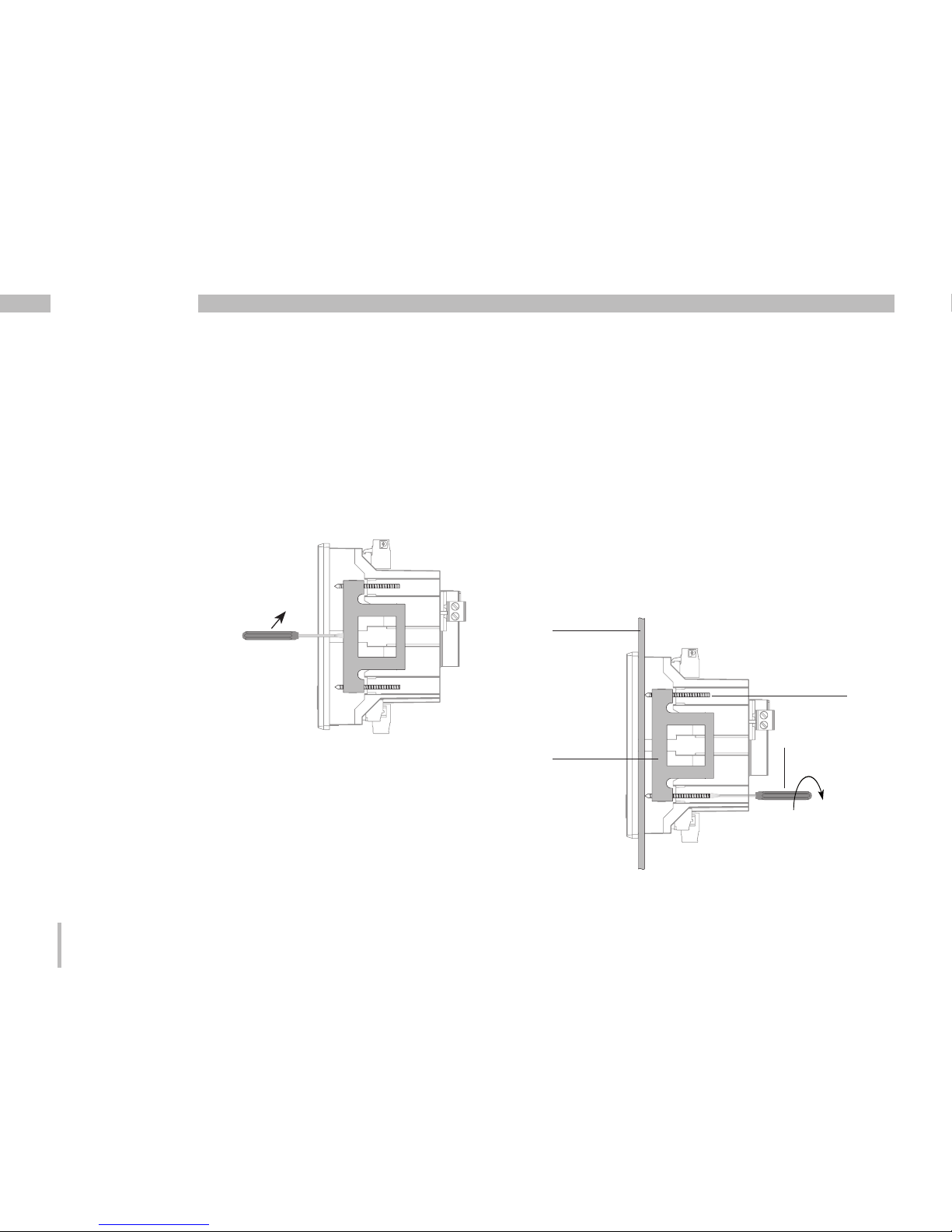
Mounting
The UMG 96RM-PN is secured in the switchboard
by the mounting clips on the side. Before insertion
the device they must be removed, for example by using
a screwdriver to lever them horizontally.
Fig. Side view of
the UMG 96RM-PN with
mounting clip.
To release the clips, use
a screwdriver to lever
them horizontally.
Mounting is then performed by sliding in and engaging
the clips and subsequently screwing in the screws.
• Screw in the clamping screws until they are just
touching the mounting plate.
• Tighten the clamping screws by two more turns
each (tightening the screws too far can destroy
the mounting clips).
Mounting plate
Clamping screw
Screwdriver
Mounting clip
When clamping screws
touch the mounting
plate: max. two
more turns to secure
the device
Page 15
15
UMG 96RM-PN
Installation
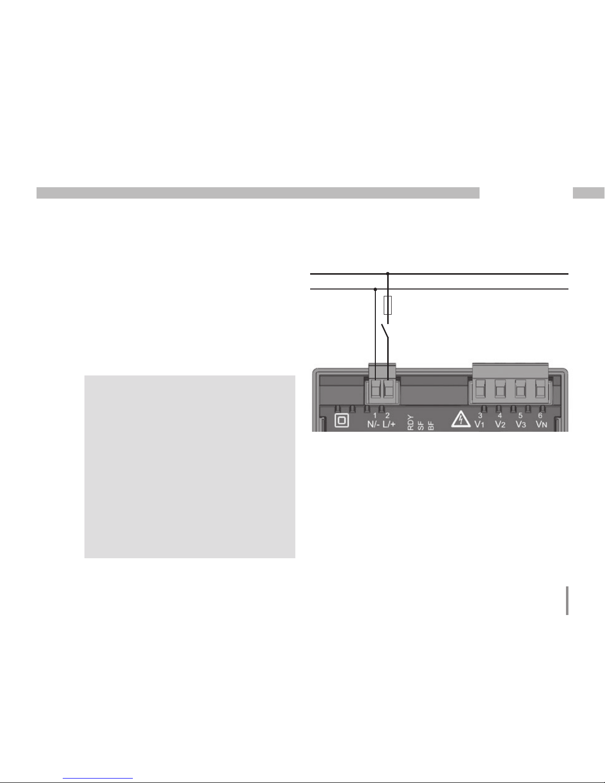
Supply voltage
The UMG 96RM-PN needs a supply voltage to operate.
The supply voltage is connected on the rear side of
the device via terminal blocks.
Before connecting the supply voltage, ensure that
the voltage and frequency correspond to the details on
the rating plate!
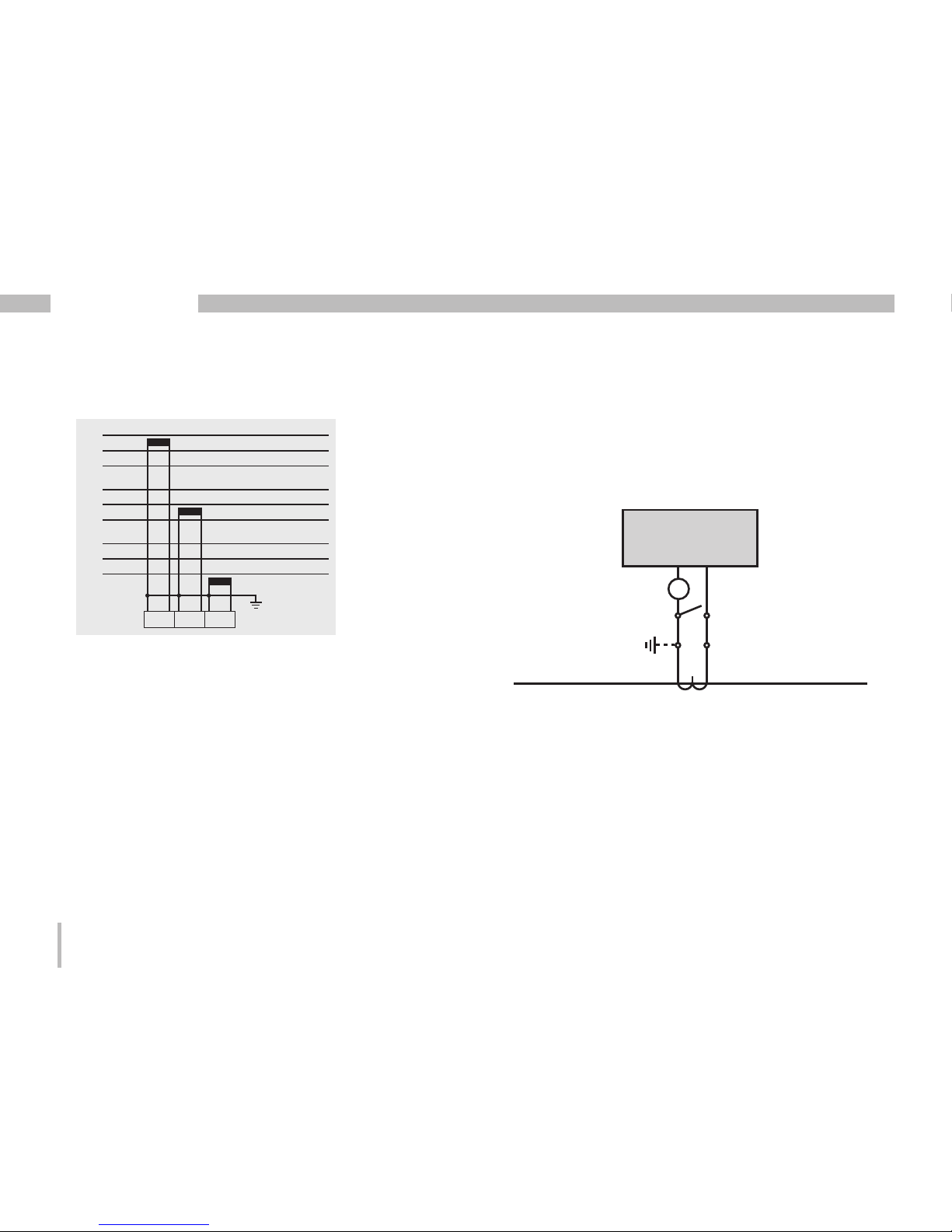
Fig. Connection example of the supply voltage to a
UMG 96RM
Circuit breaker
Fuse
N
L
m
• The supply voltage must be connected
through a fuse according to the technical data.
• If installed in a building, a disconnector
or circuit breaker must be provided for
the supply voltage.
• The disconnector must be installed
near the device and easily accessible to
the user.
• The switch must be marked as the circuit
breaker for this device.
• Voltages which are over the permitted
voltage range can destroy the device.
Page 16
16
UMG 96RM-PN
Voltage measurement
You can use the UMG 96RM-PN for voltage measurement
in TN, TT, and IT systems.
Voltage measurement in the UMG 96RM-PN is designed
for the overvoltage category 300V CAT III (measurement
voltage surge 4kV).
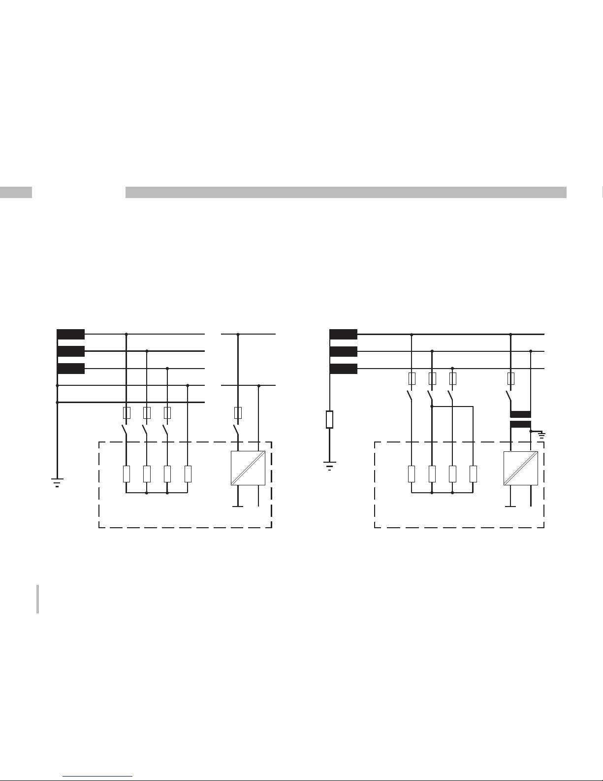
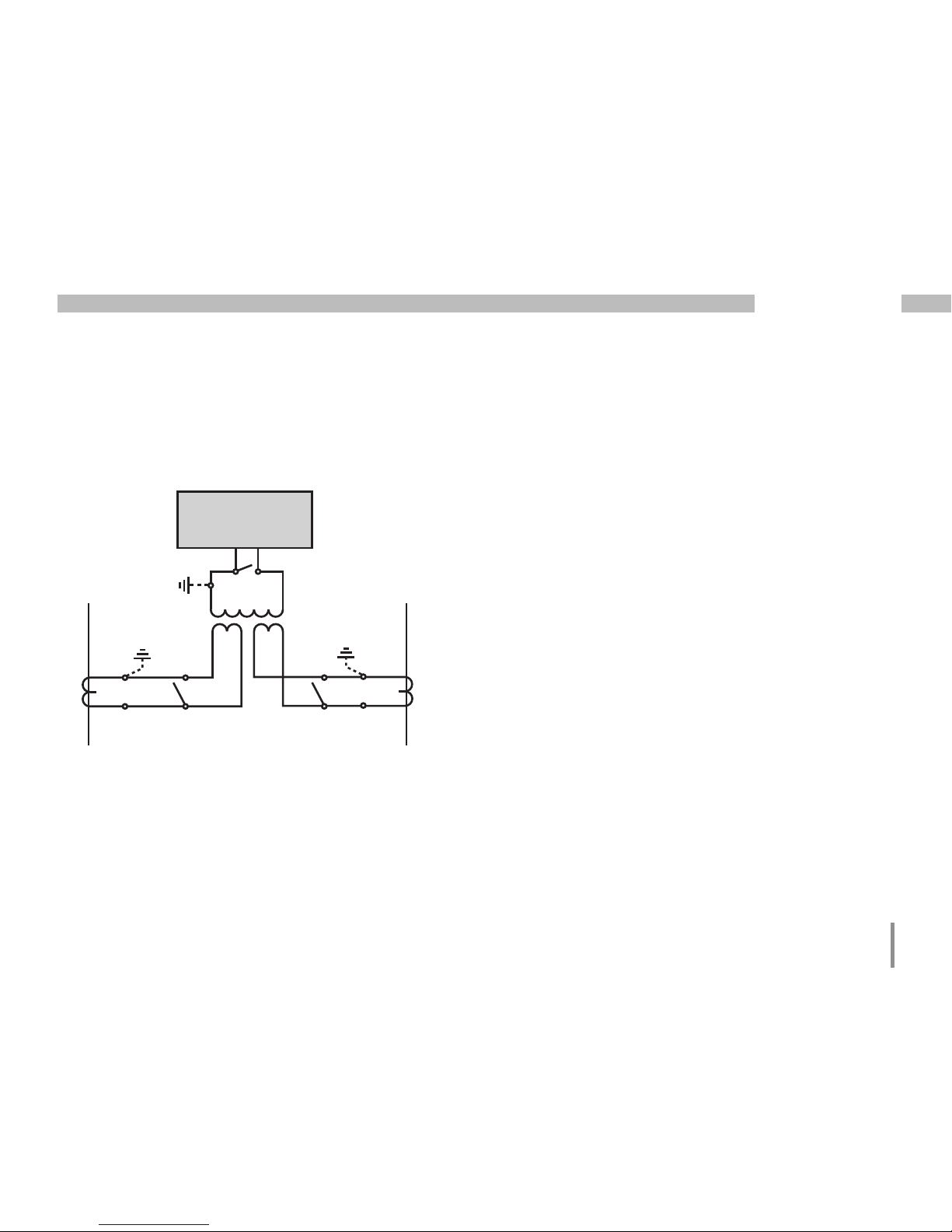
Fig. Schematic diagram - Measurement on three-phase
4-conductor systems.
Fig. Schematic diagram - Measurement on three-phase
3-conductor systems.
In systems with no N, measured values requiring an N
refer to a calculated N.
480V 50/60Hz
DC
AC/DC
L2
L3
Auxiliary supply
Voltage measurement
4M
4M
4M
4M
V1
V3V2
Earthing of
the system
Impedance
L1
VN
UMG 96RM
DC
AC/DC
PE
277V/480V 50/60Hz
L2
L3
N
L1
Auxiliary supply
Voltage measurement
4M
4M
4M
4M
V1 V3V2 VN
UMG 96RM
N
L1
240V
50/60Hz
Page 17
17
UMG 96RM-PN
Nominal network voltage
Lists of networks and their nominal network voltages
in which the UMG 96RM-PN can be used.
Three-phase 4-conductor systems with
earthed neutral conductor.
Maximum system rated
voltage
U
L-N
/ U
L-L
66V / 115V
120V / 208V
127V / 220V
220V / 380V
230V / 400V
240V / 415V
260V / 440V
277V / 480V
Fig. Table for network rated voltages i.a.w. EN606641:2003 suitable for the voltage measurement inputs.
Unearthed three-phase 3-conductor systems.
Fig. Table for network rated voltages i.a.w. EN606641:2003 suitable for the voltage measurement inputs.
Maximum system rated
voltage
U
L-L
66V
120V
127V
220V
230V
240V
260V
277V
347V
380V
400V
415V
440V
480V
Page 18
18
UMG 96RM-PN
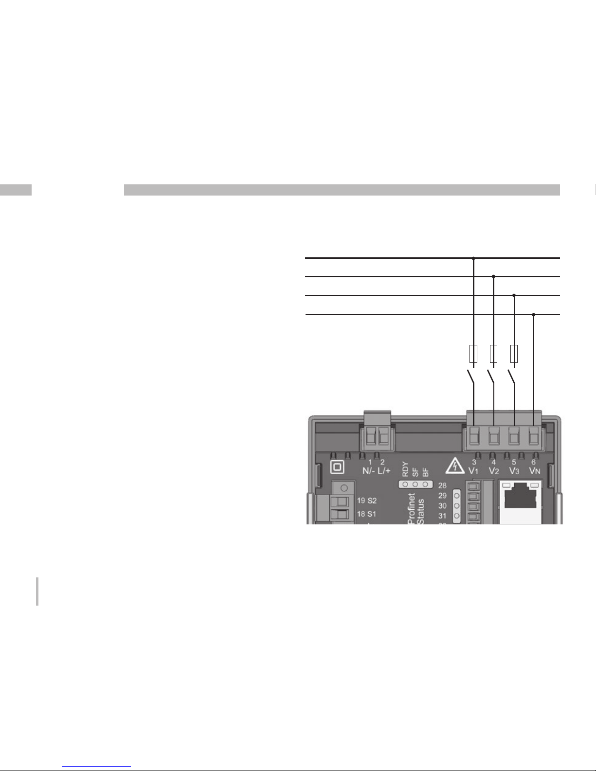
Voltage measurement inputs
The UMG 96RM-PN has three voltage measurement
inputs (V1, V2, V3).
Overvoltage
The voltage measurement inputs are suitable for
measurements in networks where overvoltages of
overvoltage category 300V CATIII (measurement voltage
surge 4kV) can occur.
Frequency
The UMG 96RM-PN requires the mains frequency for
the measurement and calculation of measured values.
The UMG 96RM-PN is suitable for measuring in
the frequency range from 45 to 65 Hz.
Fig. Example connection for measuring voltage.
Circuit breaker
Fuse
L2
L3
N
L1
Page 19

19
UMG 96RM-PN
c
Attention!
Voltages that exceed the allow nominal
network voltages must be connected
via a voltage transformer.
c
Attention!
The UMG 96RM-PN is not suitable for
measuring DC voltages.
c
Attention!
The voltage measurement inputs on
the UMG 96RM-PN are dangerous if
touched!
When connecting the voltage to be measured,
the following must be observed:
Isolation device
• A suitable circuit breaker must be fitted to disconnect
and de-energise the UMG 96RM-PN.
• The circuit breaker must be placed in the vicinity of
the UMG 96RM-PN, be marked for the user and easily
accessible.
• The circuit breaker must be UL/IEC certified.
Overcurrent protection device
• An overcurrent protection device must be used for
line protection.
• For line protection, we recommend an overcurrent
protection device as per the technical specifications.
• The overcurrent protection device must be suitable
for the line cross section used.
• The overcurrent protection device must be UL/IEC
certified.
• A circuit breaker can be used as an isolating and line
protection device. The circuit breaker must be UL/IEC
certified.
• Measured voltages and measured currents must
derive from the same network.
Page 20
20
UMG 96RM-PN
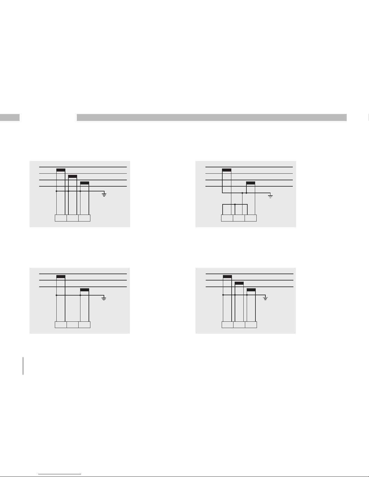
Connection schematics, voltage measurement
• 3p 4w (addr. 509= 0), factory default setting • 3p 4wu (addr. 509 = 1)
• 3p 4u (addr. 509 = 2) • 3p 2u (addr. 509 = 5)
Fig. System with three phase conductors and
a neutral conductor.
Fig. System with three phase conductors and
a neutral conductor. Measurement made with
a voltage transformer.
Fig. System with three phase conductors
without a neutral conductor. Measured values
which require an N refer to a calculated N.
Fig. System with three phase conductors without
a neutral conductor. Measurement made with
a voltage transformer. Measured values which
require an N refer to a calculated N.
L1
L2
L3
N
V1 V2 V3 V N
L1
L2
L3
N
V1 V2 V3 V N
L1
L2
L3
V1 V2 V3 V N
L1
L2
L3
V1 V2 V3 V N
Page 21
21
UMG 96RM-PN
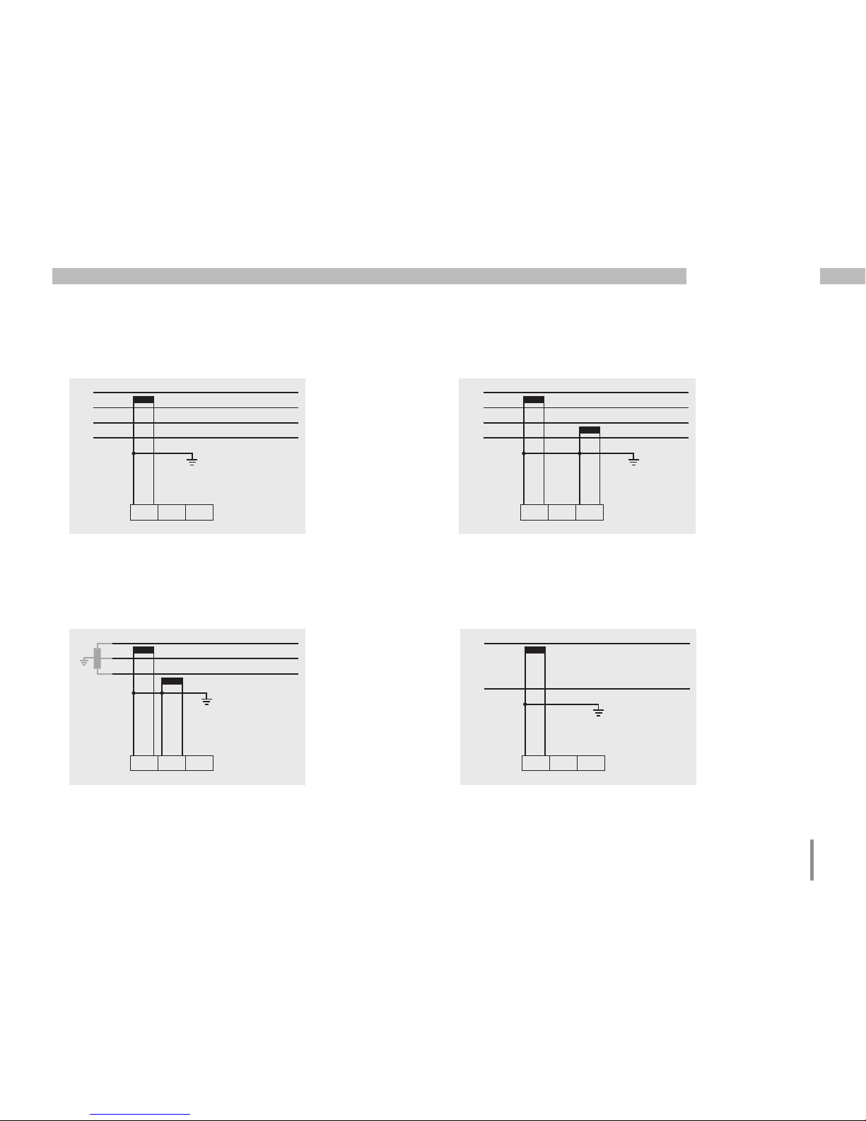
• 1p 2w (addr. 509 = 6)
• 2p 4w (addr. 509 = 3)• 1p 2w1 (addr. 509 = 4)
Fig. TN-C system with single-phase threeconductor connection. Measured values derived
from voltage measurement input V3 are taken to
be zero and are not calculated.
Fig. Measured values derived from voltage
measurement inputs V2 and V3 are taken to be
zero and are not calculated.
Fig. System with equal loading of the phases.
The measured values for voltage measurement
input V2 are calculated.
• 3p 1w (addr. 509 = 7)
Fig. 3 systems with equal loading of the phases.
L1
L2
V1 V2 V3 VN
L1
L2
L3
N
V1 V2 V3 V N
L1
N
V1 V2 V3 V N
L1
L2
L3
L1
L2
L3
L1
L2
L3
V1 V2 V3 V N
N
Page 22
22
UMG 96RM-PN
Current measurement using I1 to I4
The UMG 96RM-PN is intended for the connection of
current transformers with secondary currents of ../1A
and ../5A, via terminals I1-I4. The factory default for
the current transformer ratio is 5/5A and must be adapted
to the current transformer employed if necessary.
Direct measurement without a current transformer is not
possible with the UMG 96RM-PN.
Only AC currents can be measured - DC currents
cannot.
Current measurement input I4 only produces an
apparent current measurement, due to there being
no multiplier with a voltage. Power measurements are
therefore not possible with input I4.
c
Attention!
The current measurement inputs are dangerous
to touch.
m
The attached screw-type terminal must be
fixed using the two screws on the device!
L2
L3
N
L1
Fig. Current measurement (I1-I3) via current
transformers (connection example)
Load
Page 23
23
UMG 96RM-PN
m
Attention!
The UMG 96RM-PN is not suitable for
measuring DC voltages.
c
Earthing of current transformers!
If a connection is provided for the earthing
of secondary windings, then it must be
connected to the earth.
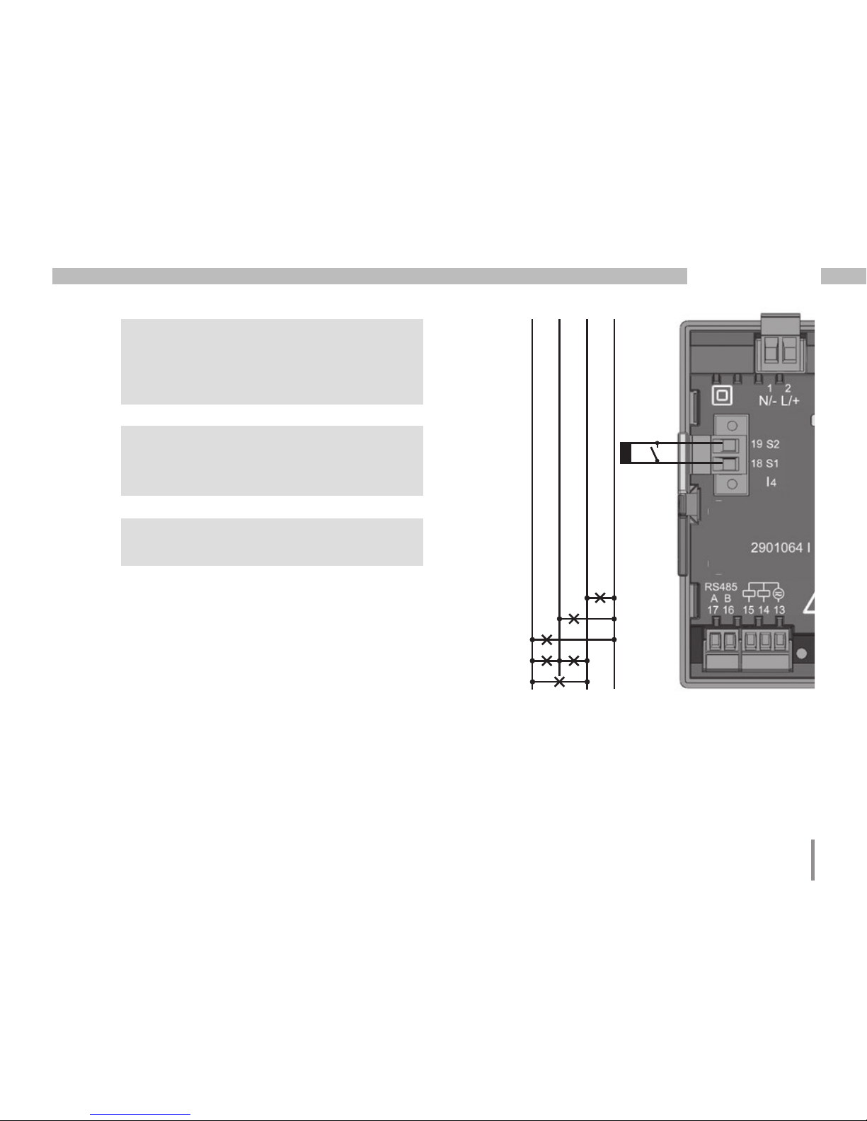
C
It is not necessary to configure a connection
schematic for measurement input I4.
L2
L3
N
L1
Fig. Current measurement (I4) via current
transformers (connection example)
Load
Page 24

24
UMG 96RM-PN
Current direction
The current direction can be individually corrected via
the existing serial interfaces or on the device for each
phase.
If incorrectly connected, a subsequent re-connection of
the current transformer is not required.
With residual current monitoring (RCM) there is no
directional sensitivity of the residual currents on
the network or load sides (not directionally sensitive).
c
Current transformer connections!
The secondary connection of the current
transformer must be short circuited on this
before the current feed to the UMG 96RMPN is disconnected!
If a test switch, which automatically shortcircuits the secondary wires of the current
transformer, is available then it is sufficient
to set this to the "Test" position insofar
as the short-circuiting device has been
checked beforehand.
c
Open-circuit current transformers!
High voltage spikes that are dangerous to
touch can occur on current transformers
that are driven with open-circuit secondary
windings!
With "safe open-circuit current transformers" the winding insulation is rated
such that the current transformer can be
driven open. However, even these current
transformers are dangerous to touch when
they are driven open-circuit.
c
Attention!
Residual current monitoring is performed
using the terminals I5 and I6 (cf. page
30). There is no directional sensitivity of
the residual currents of the network or load
sides (not directionally sensitive).
c
Earthing of current transformers!
If a connection is provided for the earthing
of secondary windings, then it must be
connected to the earth.
Page 25

25
UMG 96RM-PN
c
Attention!
The UMG96RM is only approved
for measuring current with a current
transformer.
Page 26
26
UMG 96RM-PN
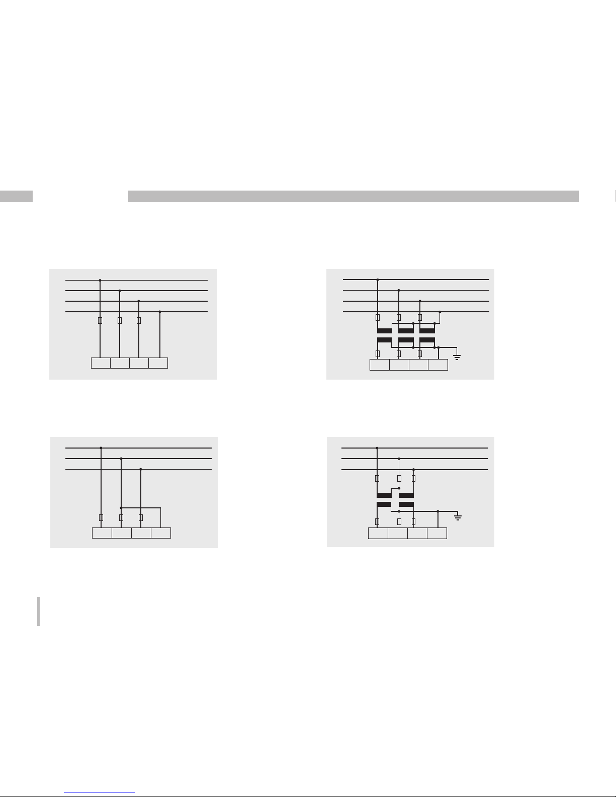
Connection schematics, current measurement (I1-I3)
• 3p 4w (addr. 510= 0), factory default setting • 3p 2i (addr. 510 = 1)
• 3p 2i0 (addr. 510 = 2) • 3p 3w3 (addr. 510 = 3)
Fig. Measurement in a three-phase network with
unequal loading.
Fig. The measured values for current
measurement input I2 are calculated.
Fig. System with equal loading of the phases.
The measured values for current measurement
input I2 are measured.
Fig. Measurement in a three-phase network with
unequal loading.
L1
L2
L3
N
I1 I2 I3
L1
L2
L3
N
I1 I2 I3
L1
L2
L3
I1 I2 I3
L1
L2
L3
I1 I2 I3
Page 27
27
UMG 96RM-PN
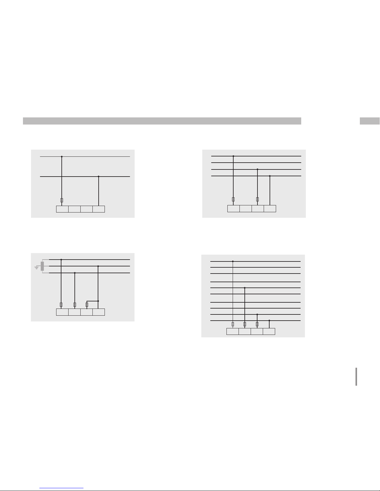
• 1p 2i (addr. 510 = 6)
• 3p 3w (addr. 510 = 4)
• 1p 2w (addr. 510 = 7)
• 2p 4w (addr. 510 = 5)
Fig. Measured values derived from current
measurement input I3 are taken to be zero and
are not calculated.
Fig. Measured values derived from current
measurement inputs I2 and I3 are taken to be
zero and are not calculated.
Fig. System with equal loading of the phases.
The measured values for current measurement
input I2 are calculated.
Fig. System with equal loading of the phases.
The measured values for current measurement
inputs I2 and I3 are calculated.
I1 I2 I3
L1
L2
L1
L2
L3
N
I1 I2 I3
L1
N
I1 I2 I3
L1
L2
L3
N
I1 I2 I3
Page 28
28
UMG 96RM-PN
Connection schematics, current measurement (I1-I3)
• 3p 1w (addr. 510 = 8)
Fig. 3 systems with equal loading of the phases.
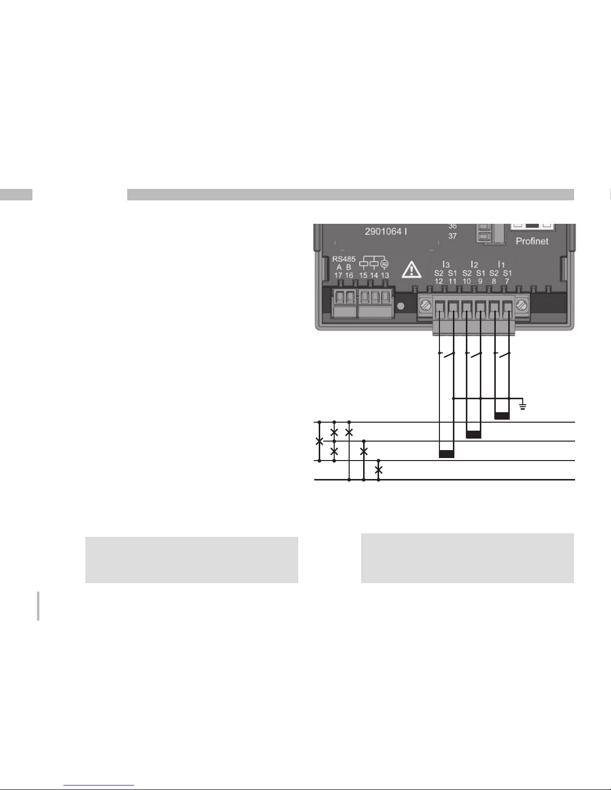
Ammeter
If you wish to measure the current not only with the UMG
96RM but rather with an ammeter too, the ammeter
must be connected to the UMG 96RM-PN in series.
Fig. Current measurement with an additional
ammeter (example).
L1
L2
L3
I1 I2 I3
L1
L2
L3
L1
L2
L3
UMG
S2
I
S
1
Einspeisung
Supply
Verbraucher
Consumer
A
(k)S
1 S2(l)
P
2(L)(K)P1
Page 29
29
UMG 96RM-PN
Total current measurement
If the current measurement is done via two current
transformers, the overall transformation ratio of
the current transformers must be programmed into
the UMG 96RM-PN.
Example: The current is measured via two current
transformers. Both current transformers have a
transformation ratio of 1000/5A. The summation
measurement is performed using a total current
transformer 5+5/5A.
The UMG 96RM-PN must then be setup as follows:
Primary current: 1000A + 1000A = 2000A
Secondary current: 5A
Fig. Current measurement via a total current transformer
(example).
UMG
S2
I
S
1
P1
P2
Einspeisung 1
Supply 1
Einspeisung 2
Supply 2
1P1
1P2
(K)
(L)
(k)
(l)
1S
2
1S1
1S1 1S2 2S1 2S2
2S1
2S2
(k)
(l)
(K)
(L)
2P
1
2P2
Verbraucher A
Consumer A
Verbraucher B
Consumer B
Page 30

30
UMG 96RM-PN
Analogue inputs
The UMG 96RM-PN has two analogue inputs, each of
which can be used for a residual current measurement
or a temperature measurement. A measurement is
performed here via terminals 32-34 (Input 1) and 35-37
(Input 2).
The analogue inputs can be used either for residual
current measuring or temperature measuring, per
the following table:
Measurement Terminal
Temperature 32/34 (Input 1) and
35/37 (Input 2)
Residual current 32/33/34 (Input 1) and
35/36/37 (Input 2)
c
Attention!
Operating equipment connected to
the analogue inputs must feature
reinforced or double insulation to the
mains supply circuits!
Example - temperature sensor:
A temperature sensor in close proximity to non-isolated
mains cables should measure within a 300V CAT III
network.
Remedy:
The temperature sensor must be equipped with
reinforced or double insulation for 300V CAT III. This
equates to a test voltage for the temperature sensor of
3000V AC (duration 1 min.).
Example - residual current transformer:
A residual current transformer should measure on
isolated mains cables within a 300V CAT III network.
Remedy:
The insulation of the mains cables and the insulation
of the residual current transformer must fulfil the basic
insulation requirements for 300V CAT III. This equates
to a test voltage of 1500V AC (duration 1 min.) for
the insulated mains cables and a test voltage of 1500 V
AC (duration 1 min.) for the residual current transformer.
Page 31

31
UMG 96RM-PN
Residual current monitoring (RCM) via I5, I6
The UMG 96RM-PN is suitable for use as a residual
current monitoring device (RCM) as well as for monitoring
AC, pulsing DC, and DC.
The UMG 96RM-PN can measure residual currents in
accordance with IEC/TR 60755 (2008-01)
of type A and
type B.
The connection of suitable external residual current
transformers with a rated current of 30 mA is performed
via the residual current transformer inputs I5 (terminals
32-34) and I6 (terminals 35-37).
Fig. Connection example of residual current
monitoring via current transformers
L2 L3N L1
Load
PE
C
Residual current transformer ratio
The GridVis software included in the scope
of the delivery can be used to individually
program the residual current transformer
inputs' transformer ratios.
Page 32

32
UMG 96RM-PN
L1 L2 L3 N I1 I2 I3
L1
L2
L3
PEN
N
PE
UMG 96RM-PN
M
3~
I5
I6
I4
C
It is not necessary to configure a connection
schematic for measurement inputs I5 and I6!
Residual
current
transformer
Residual current
transformer
Connection example, residual current monitoring
Fig. Example
UMG96RM-PN
with residual current
monitoring via
measuring inputs I5/I6.
Page 33

33
UMG 96RM-PN
Thermistor input
The UMG 96RM-PN has two thermistor inputs. The temperature
measurement is performed here via terminals 32/34 (Input 1)
and 35/37 (Input 2).
Do not exceed the total resistance load (sensor + cable)
of 4kOhm.
Fig. Example, temperature measurement
with a PT100
PT100
PT100
m
Use a shielded cable to connect the
temperature sensor.
Page 34

34
UMG 96RM-PN
RS485 interface
On the UMG 96RM-PN, the RS485 interface is designed
as a 2-pin plug contact, which communicates via the
Modbus RTU protocol (see also Programming parameters).
Correct
Incorrect
Termination resistors
The cable is terminated with resistors (120Ohm, 1/4W) at
the beginning and at the end of a segment.
The UMG 96RM-PN does not contain any termination
resistors.
Terminal strip in the cabinet.
Device with RS485 interface.
(without termination resistor)
Device with RS485 interface.
(with termination resistor on the device)
RS485 interface,
2 pin plug contact
RS485 interface,
2-pin plug contact with
termination resistor
(item no. 52.00.008)
A
B
120 Ω
RS485 bus
A
B
RS485 bus
Page 35

35
UMG 96RM-PN
Cable type
The cable used must be suitable for an environmental
temperature of at least 80°C.
Recommended cable types:
Unitronic Li2YCY(TP) 2x2x0.22 (from Lapp Kabel)
Unitronic BUS L2/FIP 1x2x0.64 (from Lapp Kabel)
Maximum cable length
1200m at a baud rate of 38.4k.
Screening
Twisted screened cable should be used for connections
via the RS485 interface.
• Earth the screens of all cables that lead to the cabinet
and at the cabinet entry.
• Connect the screens over a generous area and in a
manner that will conduct well, to a low-noise earth.
• Gather the cables mechanically above the earthing
clamp in order to avoid damage due to cable
movements.
• Use suitable cable glands to feed the cables into
the cabinet, for example, armoured conduit couplings.
Fig. Screening procedure at cabinet entry.
Cable
Strain relief
Screen braid of the cable
Earthing clamp
Noiseless ground
C
CAT cables are not suitable for bus
wiring. Use the recommended cable
types for this.
Page 36

36
UMG 96RM-PN
Bus structure
• All devices are connected in a bus structure (line) and
each device has its own address within the bus (see
also Parameter programming).
• Up to 32 subscribers can be connected together in a
single segment.
• The cable is terminated with resistors (bus termination
120Ohm, 1/4W) at the beginning and at the end of a
segment.
• With more than 32 subscribers, repeaters (amplifiers)
must be used to connect the individual segments.
• Devices for which the bus connection is switched on
must be under current.
• It is recommended that the master be placed at
the end of a segment.
• If the master is replaced with a bus connection,
the bus must be switched off.
• Replacing a slave with a bus connection that is either
switched on or de-energised can destabilise the bus.
• Devices that are not connected to the bus can be
replaced without destabilising the bus.
• The shield has to be installed continuously and needs
to be broadly and well conducting connected to an
external low voltage (or potential) ground at the end.
Fig. Bus structure
SlaveSlaveSlave
Slave Slave Slave Repeater
Slave Slave Slave Slave
Master
Speisung notwendig / power supply necessary
Busabschluß eingeschaltet / bus terminator on
T
T
T
T
T
Page 37

37
UMG 96RM-PN
Ethernet / ProfiNet interface
The Ethernet network settings should be specified by
the network administrator and set on the UMG 96RMPN accordingly.
If the network settings are not known, the UMG 96RMPN may not be integrated into the network through the
patch cable.
PC switch
for PLC
Ethernet
connection
Ethernet /
ProfiNet
device
Ethernet
connection
The UMG 96RM-PN has two identical Ethernet interfaces.
This allows another Ethernet/ProfiNet terminal to be
operated via the second interface, thus reducing outlay
on cabling.
LEDs for the Ethernet interfaces
LED
Colour
Function
1 Green Lights up when there is a
connection (a link)
2 Yellow
Lights up intermittently when
there is network activity
LED 1 LED 2
ProfiNet status LED bar
LED Status Function
RDY Off Device is not powered
RDY
Flashing
Device is being initialised
RDY On Device is ready for operation
SF On Configuration error or system error
BF On No connection
BF
Flashing
No ProfiNet connection,
in spite of physical connection
BF Off Connection to the PLC established / active
Page 38

38
UMG 96RM-PN
m
Attention!
Connection of the UMG96RM-PN to
the Ethernet may only be carried out after
consulting the network administrator!
C
Dynamic Configuration Protocol (DCP)
This function assigns unique addresses
and names to the subscribers of a
ProfiNet system, and is prioritised by
the UMG 96RM-PN.
Device master file
The device master file, abbreviated as GSD file,
describes the ProfiNet characteristics of the UMG96RMPN. The GSD file is required, for example, by the
configuration program of the PLC.
The device master file for the UMG96RM-PN has
the file name "GSDML-V2.31-JanitzaelectronicsGmbHUMG96RM-PN-xxxxxxxx.xml" (Download: www.janitza.
com).
PROFIenergy / Entity Class 2
The UMG 96RM-PN is certified as
Entity Class 2 (measurement functionality) for use of the PROFIenergy
Profile V1.1.
• A PROFIenergy device provides a defined set of functions and information, helping to standardise and reduce configuration and installation effort.
• PROFIenergy is a profile for energy management in
production systems, which is based on ProfiNet.
• Energy consumers within the system can therefore
be controlled and monitored with PROFlenergy using
open and standardised commands.
• With automated comparison of functionality between
the ProfiNet control centre and the UMG, additional
configuration and installation is rendered unnecessary.
Page 39

39
UMG 96RM-PN
Digital in-/outputs
The UMG 96RM-PN has 2 digital outputs and either
3 digital inputs or outputs, which are subdivided into
two groups (see Figure, page 40). This is based on
the rule that only the whole of Group 2 (connection 28 to
31) can function either as an input or output; differing
assignments within the same group are not possible!
Digital outputs, Group 1
• The status indicator appears on the display at K1 or
K2
• The status indicator on the display is not dependent
on an inversion being activated (NC / NO)
Digital
output 1
e.g.
Comparator group
K1/K2 display status indicator
InverterSource
Digital outputs, Group 2
• The status of the inputs and outputs in Group 2 is
indicated by the associated LED (cf. chapter LED
status bar).
Digital
output 3
e.g.
Comparator group
InverterSource
C
The digital outputs of group 2 are not AC
compatible.
Page 40

40
UMG 96RM-PN
Input/output byte coding
(Input/output data of the ProfiNet „digital IO“ module)
• If the digital inputs/outputs in group 2 are configured
as inputs, bit-oriented coding of the statuses occurs
(bit 0 to 2). In this case, coding corresponds to the
digital inputs with:
Bit 0 1 2 3 4 5 6 7
Input 3: 1 = signal is present
Input 2: 1 = signal is present
Input 1: 1 = signal is present
• The digital outputs can be controlled by setting the
corresponding bits.
• If, for example, the digital inputs/outputs in group 2
are configured as outputs, bit-oriented coding occurs
within bits 0 to 4:
Bit 0 1 2 3 4 5 6 7
Output 5: 1 = signal set
Output 4: 1 = signal set
Output 3: 1 = signal set
Output 2: 1 = signal set
Output 1: 1 = signal set
Page 41

41
UMG 96RM-PN
~
~
Group 2
Group 1
Fig. Connection
of digital/pulse
outputs
Digital outputs
These outputs are galvanically separated from
the analysis electronics using optocouplers. The digital
outputs have a common supply.
• The digital outputs of group 1 can switch AC and DC
loads. The digital outputs of group 2 can not switch
AC loads.
• The digital outputs are not short-circuit proof.
• Connected cables that are longer than 30m must be
shielded when laid.
• An external auxiliary voltage is required.
• The digital outputs of Group 1 can be used as pulse
outputs.
• The digital outputs can be controlled via Modbus and
ProfiNet.
• The digital outputs of Group 1 can output results of
comparators.
Page 42

42
UMG 96RM-PN
C
When using the digital outputs of Group 1
as pulse outputs, the auxiliary voltage (DC)
must have a max. residual ripple of 5%.
C
Functions for the digital outputs can be
adjusted clearly in the GridVis software.
A connection between the UMG 96RM-PN
and the PC via an interface is required to
use the GridVis software.
m
Attention!
Digital outputs are not short-circuit proof!
Example DC connection
Fig. Example for two relays connected
to the digital outputs
K2
External
auxiliary voltage
+
24V DC
-
K1
DC
DC
28
29
30
31
Digital Ouput 3
Digital Ouput 4
Digital Ouput 5
13
14
15
Digital Ouput 1
Digital Ouput 2
UMG 96RM-PN
Group 1:
Group 2:
LEDLEDLED
The digital inputs or outputs of
Group 2 cannot be configured as pulse
inputs/outputs. It is possible to use
them as switch inputs/outputs (ProfiNet/
Modbus, tariff switching).
C
Page 43

43
UMG 96RM-PN
Digital inputs
When Group 2 is assigned as inputs, the UMG96 RMPN has three digital inputs, each of which can have
a signal generator connected to it. If there is a signal,
the associated LED lights up green.
An input signal is detected on a digital input if a voltage of
at least 10V and maximum 28V is applied and a current
of at least 1mA and a maximum of 6mA is flowing. Wiring
longer than 30m must be screened.
Note the correct polarity of the supply voltage!
-
+
24V DC
S1
S2
External
auxiliary voltage
28
29
30
31
2k21
2k21
2k21
2k21
2k21
2k21
2k21
Digital
Input 1
Digital
Input 2
Digital
Input 3
UMG 96RM-PN
Digital inputs 1-3
Fig. Example for the connection of external switch
contacts S1 and S2 to digital inputs 1 and 2.
-
+
Fig. Connection
example of digital
inputs.
Group 2
S3
Page 44

44
UMG 96RM-PN
LED status bar
The LED status bar on the back of the device shows
the different statuses of the inputs and outputs.
Digital inputs
The LED assigned to the input lights up green if a signal
of at least 1mA is fl owing on this interface.
Digital outputs
The LED assigned to the output lights up red if the output
is set as active - irrespective of whether there is an
onwards connection to this interface.
Digital input/output 1/3
Digital input/output 2/4
Digital input/output 3/5
LED status bar
Fig. LED status bar for
the inputs or outputs
The digital inputs or outputs of
Group 2 cannot be confi gured as pulse
inputs/outputs. It is possible to use
them as switch inputs/outputs (Profi Net/
Modbus, tariff switching).
C
Page 45

45
UMG 96RM-PN
Operation
The UMG 96RM-PN is operated with buttons 1 and 2,
whereby the following distinctions are made:
• short press of button 1 or 2:
next step (+1)
• long press of button 1 or 2:
previous step (-1)
Measured values and programming data are presented
on a liquid crystal display.
A distinction is made between Display mode and
Programming mode. The requirement to enter a
password makes it possible to prevent the programming
data from being changed accidentally.
Display mode
In Display mode, using buttons 1 and 2, you can scroll
through the programmed measured value screens. In
the factory, all measured value screens listed in Profile
1 can be accessed. Up to three measured values are
displayed on each measured value screen. The measured
value rotation allows selected measured value screens
to be displayed in turn after a configurable rotation time.
Programming mode
Programming mode displays and allows for
the modification of the settings required for operation
of the UMG 96RM-PN. Pressing and holding buttons 1
and 2 at the same time for approx. 1 second takes you
(after password prompt) to Programming mode. If no
user password has been set up, you are taken directly
to the first Programming menu. Programming mode is
indicated on screen by the text "PRG".
Button 2 then allows you to switch between the following
Programming menus:
- Current transformer
- Voltage transformer
- Parameter list
- Device TCP/IP address
- Subnet mask
- Gateway address
If you are in Programming mode and no button is
pressed around 60 seconds or if buttons 1 and 2 are
pressed simultaneously for around 1 second, the UMG
96RM-PN returns to Display mode.
Page 46

46
UMG 96RM-PN
Button 1
Button 2
Delivery
Mean value
CT: Current transformer
VT: Voltage transformer
K1: Output 1
K2: Output 2
Password
Phase conductorPhase conductor
Summation measurement
Programming
mode
Min. value NT/Delivery
Max. value, HT/Consumption
Page 47

47
UMG 96RM-PN
Parameters and measured values
All of the parameters required for operation of the UMG
96RM-PN, such as the current transformer data, and
a selection of frequently required measured values are
stored in the table.
The contents of most addresses can be accessed via
the serial interface and with the buttons on the UMG
96RM-PN.
On the device you can only enter the first 3 significant
digits of a value. Values with more digits can be entered
in GridVis.
The device only ever displays the first 3 significant digits
of the value.
Selected measured values are summarised in measured
value screen profiles, and can be displayed in Display
mode with buttons 1 and 2.
The current measured value screen profile, the current
screen rotation profile and date and time can only be
read and modified via the RS485 interface.
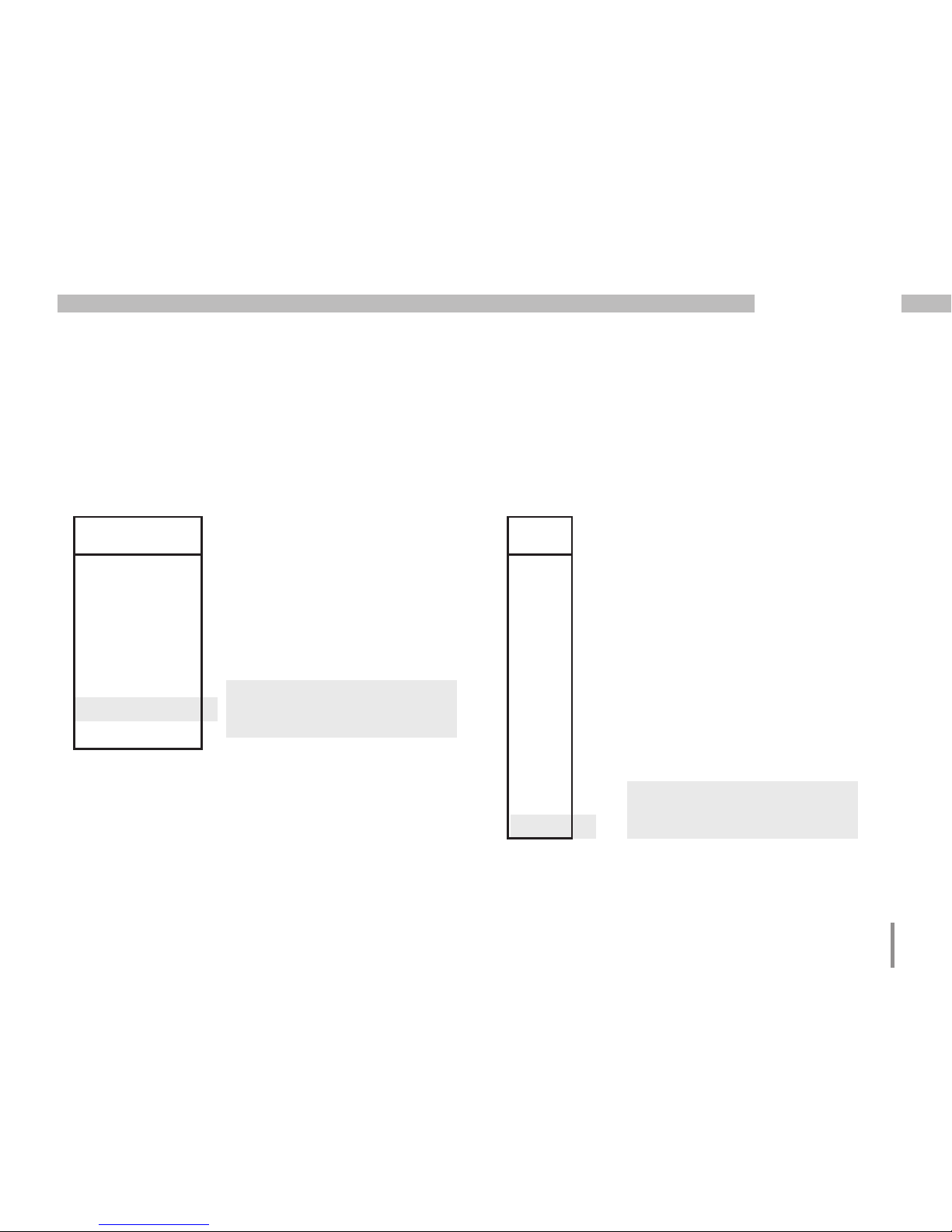
Example of a parameter screen
On the display of the UMG
96RM-PN the contents of
address "000" is displayed
as "001'. This parameter
describes (according to
the list) the device address of
the UMG 96 RM-PN (in this
case "001") within a bus.
Example of a measured value screen
In this example, the display
of the UMG 96RM-PN shows
each of the voltages L to N
as 230V. Transistor outputs
K1 and K2 are active and a
current can flow.
Page 48

48
UMG 96RM-PN
Button functions
Password
Display mode
At same time
Switch mode
Scroll
Long
Short
Measured values
A(+1)
Measured values
A(-1)
Measured values
B ...
Long Short
Programming mode
At same time
Switch mode
Scroll
Long
Short
Programming
menu +1
Programming
menu -1
Programming
Programming
menu 1
Confirm selection
(flashing)
Short: Number +1
Long: Number -1
(flashing)
Short: Value x 10
(move comma right)
Long: Value /10
(move comma left)
...
You can find an overview of
the measured value screens in
the chapter "Overview of measured
value screens".
Page 49

49
UMG 96RM-PN
Configuration
Connecting the supply voltage
The supply voltage must be connected for the
configuration of the UMG 96RM-PN.
The supply voltage level for the UMG 96RM-PN is
specified on the rating plate.
If no screen appears, check whether the supply voltage
is within the rated voltage range.
Current and voltage transformer
A current transformer of 5/5A is set in factory. Only if
voltage transformers are connected does the preprogrammed voltage transformer ratio need modifying.
When connecting voltage transformers, pay attention
to the measured voltage specified on the rating plate of
the UMG 96RM-PN!
c
Attention!
If the supply voltage does not correspond
to the voltage indicated on the rating plate,
this may lead to malfunctions and severe
damage to the device.
C
The adjustable value 0 for the primary
current transformer does not produce any
meaningful work values, and must not be
used.
m
Devices based on automatic frequency
detection require approx. 5 seconds to
determine the mains frequency. During this
time, the measured values do not comply
with the promised measurement uncertainty.
C
Prior to commissioning potential production dependant contents of the energy
counter and min/max values have to be
deleted.
Page 50

50
UMG 96RM-PN
C
Current and voltage transformer
The GridVis software can be used to
individually program the transformation
ratios for each current or voltage
measurement input.
Only the transformation ratio for the
respective group of current measurement
inputs I1-I3 or voltage measurement inputs
V1-V3 can be set on the device.
The transformation ratio of current trans-
former input I4 and the residual current
transformer inputs I5, I6 must be set in the
GridVis software.
Current transformer input I4
Current transformer input I4 only produces
an apparent current measurement, due to
there being no multiplier with a voltage.
Power measurements with the input are
therefore not possible. The transformation
ratio can be set in the GridVis software.
Fig. Screen for configuration of the current and
voltage transformer in the GridVis software.
C
If the device is operated within a PROFINET
environment, parameters listed in the GSD
file can also be configured via the PLC.
Page 51

51
UMG 96RM-PN
Programming the current transformer for I1-I3
Switch to Programming mode:
• Switching to Programming mode is done by pressing
buttons 1 and 2 simultaneously. If a user password
has been set, then the password prompt appears
with "000". The first digit of the user password flashes
and can be modified with button 2. Pressing button 2
selects the next digit (it starts flashing). If the correct
combination of number has been entered or if no user
password was set, you are taken to Programming
mode.
• The symbols for Programming mode "PRG", and for
the current transformer "CT" appear.
• The selection is confirmed with button 1.
• The first digit of the input range for the primary current
flashes.
Enter the current transformer primary current:
• Modify the flashing digit with button 2.
• Use button 1 to select the next number you wish to
modify. The selected digit to be modified flashes. If
the entire number flashes, the decimal point can be
moved with button 2.
Enter the current transformer secondary current:
• Only 1A or 5A can be set as the secondary current.
• Use button 1 to select the secondary current.
• Modify the flashing digit with button 2.
Exit Programming mode:
• Exit Programming mode by pressing button 1 and 2
at the same time.
Page 52

52
UMG 96RM-PN
Current transformer symbol
Unit indicator
Current transformer, primary
Programming mode
Current transformer, secondary
Unit indicator
Voltage transformer, primary
Programming mode
Voltage transformer,
secondary
Voltage transformer
symbol
Programming the voltage transformer
• Switch to programming mode as described.
The symbols for Programming mode "PRG", and for
the current transformer "CT" appear.
• Button 2 is used to switch to the Voltage transformer
settings.
• The selection is confirmed with button 1.
• The first digit of the input range for the primary voltage
flashes. The same as assigning the current transformer
ratio from the primary to the secondary current,
the ratio can be set from the primary to the secondary
voltage of the voltage transformer.
Page 53

53
UMG 96RM-PN
Fig. Password prompt
If a password was set, it can be
entered with buttons 1 and 2.
Fig. Current transformer
programming mode
Buttons 1 and 2 can be used
to modify the primary and
secondary current (cf. page 51).
Fig. Voltage transformer
programming mode
Buttons 1 and 2 can be
used to modify the primary
and secondary voltage (cf.
page 52).
Programming parameters
Switch to Programming mode
• Switch to programming mode as described.
The symbols for Programming mode "PRG", and for
the current transformer "CT" appear.
• Button 2 is used to switch to the Voltage transformer
settings. Repeatedly pressing button 2 displays
the first parameter in the parameter list.
Modify a parameter
• Confirm the select with button 1.
• The last selected address is displayed with
the associated value.
• The first digit of the address flashes and can be
modified with button 2. Button 1 is used to select
the digit, which is then in turn modified with button 2.
Modify a value
• Once the desired address has been set, a digit of
the value can be selected with button 1 and modified
with button 2.
Exit Programming mode
• Exit Programming mode by pressing button 1 and 2
at the same time.
Fig. Parameter screen
programming mode
Buttons 1 and 2 can be
used to modify the individual
parameters (cf. page 47).
Page 54

54
UMG 96RM-PN
TCP/IP configuration
Each device in an Ethernet has a unique TCP/IP address,
which can be assigned manually for the UMG 96RM-PN.
The 4-byte-long device address (Byte 0 to 3) is appended
within the TCP/IP configuration with the subnet mask
and gateway details.
If the device is integrated into a ProfiNet environment,
however, the address is generally assigned by the DCP
function.
Set the device's TCP/IP address (addr)
• Switch to programming mode as described.
The symbols for Programming mode "PRG", and for
the current transformer "CT" appear.
• Pressing button 2 three times takes you to the TCP/IP
settings for device addressing.
• Select the desired digit using button 1. Selection is
indicated by the digit flashing.
• The selected digit can be adjusted with the 2 button.
• Use button 1 to select the next digit and set it with
button 2 again.
• Once Byte 0 of the TCP/IP address is set, bytes 1
to 3 of the address can be set with button 1. Then
the display jumps back to Byte 0 (none of the digits
are flashing).
Designation
Byte identifier
of the address (e.g. Byte 0)
Address value, Byte 0
Fig. TCP/IP address, Byte 1
A TCP/IP address consists
of 4 bytes with the following
structure:
xxx.xxx.xxx.xxx
Byte 1Byte 0 Byte 2 Byte 3
Fig. TCP/IP address
Byte 2, value 003
Fig. TCP/IP address
Byte 3, value 177
192.168.003.177Example:
Page 55

55
UMG 96RM-PN
Set the subnet mask (SUb):
• In programming mode, button 2 takes you to
the Subnet mask settings (SUb on screen).
• Use the button 1 to select the desired digit and set it
with button 2. Repeat this step for every digit in Byte
0 to 3, the same as when setting the device's TCP/
IP address.
• Once the display returns to Byte 0 (none of the digits
flashing) you can set the gateway.
Set the gateway address (GAt):
• In programming mode, button 2 takes you to
the Gateway address settings (GAt on screen).
• Use the 1 and 2 buttons to set the desired gateway
address in Byte 0 to 3, in the same way as the above
descriptions.
C
Changes are only applied after exiting
programming mode.
Fig. Gateway (GAt),
Byte 0, value 192
Fig. Subnet mask (SUb),
Byte 0, value 255
m
Attention!
Connection of the UMG96RM-PN to
the Ethernet may only be carried out after
consulting the network administrator!
C
Dynamic Configuration Protocol (DCP)
This function assigns unique addresses
and names to the subscribers of a
ProfiNet system, and is prioritised by
the UMG 96RM-PN.
Page 56

56
UMG 96RM-PN
RS485 device address (addr. 000)
If multiple devices are connected together via the RS485
interface, then a Master device is only able to distinguish
between these devices based on their device address.
Therefore each device on a network must have a different
device address. Addresses can be set in the range from
1 to 247.
C
The setting range for the device address is
between 0 and 255. The values 0 and 248
to 255 are reserved and must not be used.
Setting Baud rate
0 9.6 kbps
1 19.2 kbps
2 38.4 kbps
3 57.6 kbps
4 115.2 kbps (factory setting)
RS485 baud rate (addr. 001)
A common baud rate can be set for the RS485 interfaces.
A common baud rate must be selected in the network.
Address 003 can be used to set the number of stop bits
(0=1Bit, 1=2Bits). Data Bits (8) are preset to fixed values.
Page 57

57
UMG 96RM-PN
User password (addr. 050)
To make it harder to accidentally modify the programming
data, a user password can be set. You can only switch
to the following Programming menus after entering
the correct user password.
No user password is set in the factory. In this case,
the Password menu is skipped and you are taken
immediately to the Current transformer menu.
If a user password has been set, then the Password
menu appears with "000" on the screen.
The first digit of the user password flashes and can
be modified with button 2. Pressing button 1 selects
the next digit (it starts flashing).
Only when the right combination of numbers is entered,
takes you to the Programming menu for the current
transformer.
Forgot password
If you no longer remember your password, you can only
delete it using the GridVis PC software.
In order to do so, connect the UMG96RM-PN to the PC
with a suitable interface. More information can be found
in the GridVis assistant.
Page 58

58
UMG 96RM-PN
Averaging method
The used exponential averaging method achieves at
least 95% of the measured value after the set averaging
time.
Min. and max. values
All measured values are measured and calculated every
10/12 periods. Min. and max. values are determined for
most measured values.
The min. value is the lowest measured value measured
since the last time the values were cleared. The min.
value is the lowest value measured since the last time
the values were cleared. All min. and max. values are
compared with the associated measured values, and
overwritten if the value is under the min. value or over
the max. value.
The min. and max. values are stored every 5 minutes to
an EEPROM without the date and time. This means that,
if there is failure of the supply voltage, only the min. and
max. values for the last 5 minutes can be lost.
Clearing the min. and max. values (addr.506)
If "001" is written to address 506, all min. and max.
values are cleared simultaneously.
Parameters
Mean value
Averages for the current, voltage, and power measured
values are calculated over an adjustable period.
The averages are identified by a bar over the top of
the measured value.
The averaging time can be selected from a list of 9 fixed
averaging times.
Current averaging time (addr. 040)
Power averaging time (addr. 041)
Voltage averaging time (addr. 042)
Setting Averaging time/Sec.
0 5
1 10
2 15
3 30
4 60
5 300
6 480 (factory setting)
7 600
8 900
Page 59

59
UMG 96RM-PN
Mains frequency (addr. 034)
To automatically determine the mains frequency, a
voltage L1-N of greater than 10Veff must be applied to
voltage measurement input V1.
The sampling rate for the current and voltage inputs is
then calculated from the mains frequency.
If the measured voltage is absent, it is not possible to
determine the mains frequency, which makes it impossible
to calculate the sampling rate. The acknowledgeable
error message "500" appears.
Voltage, current, and all other values derived from these
are calculated and still displayed based on the last
frequency measurement or on possible line interfaces.
However, these determined measured values are no
longer subject to the specified level of accuracy.
Once the frequency can be measured again, the error
message disappears automatically approx. 5 seconds
after the voltage returns.
The error is not displayed if a fixed frequency is set.
Setting range: 0, 45 - 65
0 = Frequency determined automatically
The mains frequency is determined from the measured
voltage.
45 - 65 = Fixed frequency
The mains frequency is preset to a fixed value.
Page 60

60
UMG 96RM-PN
Power meters
The UMG 96RM-PN has power meters for effective
energy, reactive energy, and apparent energy.
Reading off the effective energy
Total effective energy
The effective energy shown
in this example is:
12 345 678 kWh
The effective energy shown
in this example is:
134 178 kWh
Resetting energy meters (addr. 507)
The effective, apparent, and reactive energy meters can
only be reset as one.
To reset the energy meters, address 507 must be
described with "001".
Resetting the power meters discards
the data in the device.
To avoid possible data loss, you should
read out and store these measured values
with the GridVis software.
C
C
Prior to commissioning potential production dependant contents of the energy
counter and min/max values have to be
deleted.
Page 61

61
UMG 96RM-PN
Harmonics
Harmonics are the integer multiples of a fundamental
oscillation.
On the UMG 96RM-PN the fundamental oscillation of
the voltage must be in the range from 45 to 65 Hz. At this
fundamental oscillation the calculated harmonics relate
to the voltages and currents.
Harmonics up to 40 times the fundamental oscillation
are captured.
The harmonics for the currents are given in amps,
the harmonics for the voltages in volts.
Fig. Screen for the 15th harmonic of the current in
phase L3 (example).
Number of
harmonic
Phase L3
Current harmonic
Value
C
Harmonics are not displayed in the factory
default setting.
Total Harmonic Distortion (THD)
THD is the ratio of the effective value of the harmonics to
the effective value of the fundamental oscillation.
Phase L3
Voltage
Value
Fig. Screen for the Total harmonic distortion (THD)
of the voltage from phase L3 (example).
Total harmonic distortion of the current (THDI):
Total harmonic distortion of the voltage (THDU):
Page 62

62
UMG 96RM-PN
Rotation time (addr. 039)
Setting range: 0 to 60 seconds
If 0 seconds is set, then there is no rotation between
the measured value screens selected for measured
value rotation.
The rotation time applies to all screen rotation profiles.
Screen rotation profile (addr. 038)
Setting range: 0 to 3
0 - Screen rotation profile 1, preassigned.
1 - Screen rotation profile 2, preassigned.
2 - Screen rotation profile 3, preassigned.
3 - Screen rotation profile, customer-specific.
Measured value screens
After the power is restored, the UMG 96RM-PN displays
the first measured value table from the current screen
profile. So that the selection of measured values to be
displayed remains clear, at the factory only one part of
the available measured values is pre-programmed to be
called up in the measured value screen. If you desire to
display other measured values on the screen of the UMG
96RM-PN, select a different screen profile.
Measured value rotation
All measured values are calculated every 10/12 periods,
and are available once a second in the measured value
screens. Two methods are available for bringing up
the measured value screens:
• The automatically rotating display of selected
measured value screens, referred to here as
"measured value rotation".
• Choosing a measured value screen from a selected
screen profile, using buttons 1 and 2.
Both methods are available simultaneously. Measured
value rotation is active when at least one measured value
screen is programmed with a rotation time greater than
0 seconds.
Pressing a button allows you to scroll through
the measured value screens for the selected screen
profile. If no button is pressed for around 60 seconds,
the device switches to measured value rotation, and
the measured values from the selected screen rotation
profile programmed measured value screens are
displayed in succession.
Page 63

63
UMG 96RM-PN
Screen profile (addr. 037)
Setting range: 0 to 3
0 - Screen profile 1, fixed preassigned value.
1 - Screen profile 2, fixed preassigned value.
2 - Screen profile 3, fixed preassigned value.
3 - Screen profile, customer-specific.
C
The customer-specific profiles (screen
rotation profile and screen profile) can only
be programmed via the GridVis software.
C
Profile setting
The GridVis software provides a clear
overview of the profiles (screen rotation profile
and screen profile). In the software the Device
configuration can be used to configure the
profiles; customer-specific screen profiles can
also be programmed.
A connection between the UMG 96RM-PN
and the PC is required to use the GridVis
software.
Fig. Profile setting screen in the GridVis software.
Page 64

64
UMG 96RM-PN
Direction of the rotating field
The direction of the rotating field of the voltages and
the frequency of phase L1 are displayed in a screen.
The direction of the rotating field specifies the phase
sequence in three-phase power grids. A “right-hand
rotation field” usually exists.
In the UMG 96RM-PN, the phase sequence is tested and
indicated on the voltage measurement inputs. A movement
of the character string in a clockwise direction means
there is a “right-hand rotation field” and an anticlockwise
movement indicates a “left-hand rotation field”.
The direction of the rotating field is only determined when the
measuring and supply voltage inputs are fully connected. If
a phase is missing or if two identical phases are connected,
the direction of the rotating field is not established and
the character string is stationary on the screen.
Fig. Screen for the mains
frequency (50.0)
and the direction of
the rotating field.
Fig. Direction of
the rotating field not
detectable.
LCD contrast (addr. 035)
The preferred direction for observing the LCD display
is from below. The contrast of the LCD display can be
adjusted by the user. The contrast can be set in the range
from 0 to 9 in steps of 1.
0 = Characters very bright
9 = Characters very dark
Factory default setting: 5
Backlight
The backlight enables good legibility of the LCD display
under poor visual conditions. The brightness can be
controlled by the user in the range from 0 to 9 in steps
of 1.
The UMG 96RM-PN has two different types of backlight:
- Operating lighting
- Standby lighting
Page 65

65
UMG 96RM-PN
Operating lighting (addr. 036):
The operating lighting is activated by the push of a
button or upon restart.
Standby lighting (addr. 747)
This type of backlight is activated after a customisable
period of time (addr. 746). If there are no button presses
during this period, the device switches to standby
lighting.
If buttons 1 - 3 are pressed, the device switches to
operating lighting and the defined period begins again
from scratch.
If the brightness values are the same for both types
of lighting then no change is discernible between
the backlight and standby lighting.
Addr. Description Setting
range
Default
036 Brightness for
operating lighting
0 to 9 6
746 After how long to
switch to standby
lighting
60 to 9999
secs
900
secs
747 Brightness for standby
lighting
0 to 9 0
0 = Minimum brightness, 9 = Maximum brightness
C
DCP "Identify Station" signal of the PLC:
If the PLC sends control signals for device
identification to the device, the backlight
switches between maximum and
minimum brightness (causing the display
lighting to "flash"). To achieve this there is
usually a "Flash" button in the PLC.
Page 66

66
UMG 96RM-PN
Time logging
The UMG 96RM-PN logs the operating hours and the total
running time of each comparator, whereby the time
• for the operating hours is measured with a resolution
of 0.1 hrs and displayed in hours or
• the total running time of the comparators is displayed
in seconds (when 999,999 secs is reached, the number
is displayed in hours).
For a query using the measured value screens, the times
are indicated with the numbers 1 to 6:
None = Operating hours counter
1 = Total running time, Comparator 1A
2 = Total running time, Comparator 2A
3 = Total running time, Comparator 1B
4 = Total running time, Comparator 2B
5 = Total running time, Comparator 1C
6 = Total running time, Comparator 2C
A maximum of 99,999.9 hrs (=11.4 years) can be shown
on the measured value screen.
Fig. Measured value screen
Operating hours counter
The UMG 96RM-PN shows the
number 140.8 hrs in the operating
hours counter. This corresponds
to 140 hours and 80 industry
minutes. 100 industry minutes
correspond to 60 minutes. In this
example, the 80 industry minutes
correspond to 48 minutes.
Operating hours counter
The operating hours counter measures the time in which
the UMG 96RM-PN captures and displays measured values.
The time for the operating hours is measured with
a resolution of 0.1 hrs and displayed in hours.
The operating hours counter cannot be reset.
Total running time, comparator
The total running time of a comparator is the sum of all
times for which there was a threshold value violation in
the comparator result.
The total running times of the comparators can only be
reset via the GridVis software. The reset is performed for
all total running times.
Page 67

67
UMG 96RM-PN
Serial number (addr. 754)
The serial number displayed by the UMG 96RM-PN has
six digits and is a part of the serial number displayed on
the rating plate.
The serial number cannot be modified.
Software release (addr. 750)
The software for the UMG 96RM-PN is continuously
improved and expanded. The software version in
the device is identified by a three-digit number,
the software release. The software release cannot be
modified by the user.
Serial number indicator
Serial number as stated
on the rating plate:
XX00-0000
Page 68

68
UMG 96RM-PN
Commissioning
Connecting the supply voltage
• The supply voltage level for the UMG 96RM-PN is
specified on the rating plate.
• After applying the supply voltage, the UMG 96RM
switches to the first measured value screen.
• If no display appears, check whether the power supply
voltage is within the rated voltage range.
Connecting the measured voltage
• Measurement of voltages in networks with over
300VAC to earth must be connected via voltage
transformers.
• After connecting the measured voltages, the measured
values displayed by the UMG 96RM-PN for the L-N
and L-L voltages must correspond to those at
the voltage measurement input.
m
Attention!
Voltages and currents that are outside
the permissible measurement range
can cause personal injury and lead to
the destruction of the device.
m
Attention!
If the supply voltage does not correspond
to the voltage indicated on the rating plate,
this may lead to malfunctions and severe
damage to the device.
m
Attention!
The UMG 96RM is not suitable for
measuring DC voltages.
Applying the measuring-circuit voltage
The UMG 96RM-PN is designed for the connection of ..
/1A and .. /5A current transformers.
Only AC currents can be measured via the current
measurement inputs - DC currents cannot.
Short circuit all current transformer outputs except for
one. Compare the currents displayed by the UMG 96RM
with the applied current.
Bearing in mind the current transformer conversion
ratio, the current displayed by the UMG 96RM-PN must
correspond with the input current.
The UMG 96RM-PN must display approx. zero amperes
in the short circuited current measurement inputs.
The current transformer ratio is factory-set to 5/5A and
must be adapted to the current transformer used if
necessary.
Page 69

69
UMG 96RM-PN
Direction of the rotating field
Check the direction of the rotating field voltage in
the measured value display of the UMG 96RM.
A “right-hand” rotation field usually exists.
Checking the phase assignment
The phase conductor assignment to the current transformer
is correct if a current transformer is short-circuited on
the secondary side and the current displayed by the UMG
96RM-PN drops to 0A in the associated phase.
Checking the power measurement
Short-circuit all current transformer outputs except for
one and check the displayed power outputs.
The UMG 96RM-PN may only display one power output in
the phase with a non-short-circuited current transformer
input. If this is not the case, check the connection of
the measured voltage and the measuring-circuit current.
If the effective power amount is correct but the sign
of the power output is negative, this could have two
possible causes:
• S1(k) and S2(l) are reversed at the current transformer.
• Effective energy is being supplied back into
the network.
Applying the residual current
Connect residual current transformer only to the I5 and
I6 inputs with a rated current of 30mA! Both residual
current inputs can measure AC currents, pulsing direct
currents and DC currents.
Bearing in mind the current transformer ratio, the
residual current displayed by the UMG96RM-PN must
correspond with the input current.
The current transformer ratio is factory-set to 1/1A and
must be adapted to the residual current transformer
used if necessary.
C
It is not necessary to configure a
connection schematic for residual current
inputs I5 and I6.
C
The UMG96RM-PN requires the mains
frequency for residual current monitoring. For
this purpose, the measured voltage should be
applied or a fixed frequency should be set.
Page 70

70
UMG 96RM-PN
Failure monitoring (RCM) for I5, I6
The UMG96RM-PN enables continuous monitoring of
the connection to the residual current transformer on
inputs I5 and I6.
Modbus addr. Value / Function
553 (I5)
554 (I6)
0 = Transformer monitoring, I5 and I6
deactivated
1 = Transformer monitoring, I5 and I6
activated
If there is an interruption in the connection to the current
transformer, this state is recorded in certain registers or
indicated in the GridVis software:
Modbus addr. Value / Function
10014 (I5)
10015 (I6)
0 = Connection of the residual current
transformer to I5 and I6 error-free
1 = Error in the current transformer
connection to I5 and I6
m
The monitoring of the connection to
the residual current transformer is only
available in the AC mode!
Residual current transformers of Type A
must be used for transformer monitoring!
We recommend configuring the residual
current measurement settings in GridVis.
C
Page 71

71
UMG 96RM-PN
Checking the sum powers
If all voltages, currents, and powers for the phase
conductor in question are displayed properly, then
the sum powers measured by the UMG 96RM must also
be correct. For confirmation, the sum powers measured
by the UMG 96RM should be compared with the effective
and reactive power meter located in the supply.
Checking the measurement
Once all voltage and current measurement inputs are
properly connected, the signal phase and sum powers
are also calculated and displayed properly.
Checking the single phase powers
If a current transformer is assigned to the wrong phase
conductor, the associated power will also be measured
and displayed incorrectly.
The assignment of phase conductor to current
transformer on the UMG 96RM-PN is correct when
there is no voltage between the phase conductor and
the associated current transformer (primary).
To ensure that a phase conductor on the voltage
measurement input is assigned to the right current
transformer, you can short-circuit the current transformer
in question on the secondary side. The apparent power
displayed by the UMG 96RM-PN must be zero in this
phase.
If the apparent power is displayed correctly but
the effective power has a "-" sign, the current transformer
terminals are reversed or power is being supplied to
the power company.
Page 72

72
UMG 96RM-PN
RS485 interface
The MODBUS RTU protocol with CRC check on
the RS485 interface can be used to access the data from
the parameter and the measured value lists.
Address range: 1 to 247
Factory default setting: 1
The device address is factory set to 1 and the baud rate
to 115.2 kbps.
Modbus functions (slave)
04 Read input registers
06 Preset single register
16 (10Hex) Preset multiple registers
23 (17Hex) Read/write 4X registers
The sequence of bytes is high before low byte (Motorola
format).
Transmission parameters:
Data bits: 8
Parity: None
Stop bits (UMG 96RM): 2
External stop bits: 1 or 2
Number format: short 16 bit (-2
15
to 215 -1)
float 32 bit (IEEE 754)
The message length must not exceed
256 bytes.
C
Broadcast (address 0) is not supported
by the device.
C
Page 73

73
UMG 96RM-PN
The "Response" of the UMG96 RM-PN can appear as
follows:
Name Hex Note
Device address 01 UMG 96RM, address = 1
Function 03
Byte meter 06
Data 00 00hex = 00dez
Data E6 E6hex = 230dez
Error check (CRC) -
The L1-N voltage read by address 19000 is 230V.
Example: Reading the L1-N voltage
The L1-N voltage is saved in the measured value list
at address 19000. The L1-N voltage is available in
the FLOAT format.
Address = 01 is approved as the UMG 96RM-PN device
address.
The Query Message appears as follows:
Name Hex Note
Device address 01 UMG 96RM, address = 1
Function 03 "Read holding reg."
Start addr. Hi 4A 19000dez = 4A38hex
Start addr. Lo 38
Ind. Value Hi 00 2dez = 0002hex
Ind. Value Lo 02
Error check -
Page 74

74
UMG 96RM-PN
Digital outputs
The UMG 96RM-PN has two digital outputs in Group 1.
Another three digital outputs can be set in Group 2.
You can optionally assign different functions to the digital
outputs.
The settings of the functions in the confi guration menu
must be made using the GridVis software.
Fig.: GridVis software, confi guration menu
Digital inputs/outputs
28 29 30 3113 14 15
24V
DC
K1 K2
=
-
+
K3 K4
K5
=
-
+
=
+
-
S1 S2 S3
Group 1 Group 2
Fig.: Digital outputs of Group 1 and digital
inputs/outputs of Group 2
Page 75

75
UMG 96RM-PN
Digital output status indicators
The status of the switch outputs of Group 1 is displayed
on the display of the UMG 96RM-PN by circle symbols.
Statuses of the digital inputs of Group 2 - as described
in the chapter "LED status bar" - are displayed by
the rearwards-facing LEDs.
Statuses of the digital outputs of Group 1
Status of Digital output 1
Status of Digital output 2
Group 1
A current of <1mA can flow.
Digital output 1: addr. 608 = 0
Digital output 2: addr. 609 = 0
A current of up to 50mA can flow.
Digital output 1: addr. 608 = 1
Digital output 2: addr. 609 = 1
Since the display is only updated once
a second, status changes in the outputs
which are more rapid than this cannot be
displayed.
C
Page 76

76
UMG 96RM-PN
Functions of the digital outputs of Group 1
You can optionally assign the following functions to the two digital outputs of Group 1:
Comparator A
Comparator B
Comparator C
Logic
Digital
output 1
13
14
Selection
of source
Comparator group 1
Pulse output
UMG 96RM-PN
Addr. 100 = Measured value address
Addr. 106 = Minimum pulse length
Addr. 102 = Pulse value
0/1
0/1
0/1
0/1
Inverter
Addr. 201=0 (not inverted)
Addr. 201=1 (inverted)
0/1
Addr. 608 =0
Status of
Digital output 1
Result
Addr. 616
Modbus
External source
RS485
Addr. 602 = 0 (Off), >0 (On)
External value
Ethernet / ProfiNet
Addr. 527 = 0 (Off), >0 (On)
External value
Addr. 200 =0
Addr. 200 =1
Addr. 200 =2
Addr. 200 =5
0/1
ProfiNet (PLC)
External source
Display
K1 K2
Fig.: Overview block diagram for Digital output 1
Digital output 2
Addr. 202 = 0 Result of Comparator group 2
Addr. 202 = 1 Pulse output
Addr. 202 = 2 Value from external source Modbus
Addr. 202 = 2 Value from external source ProfiNet
Digital output 1
Addr. 200 = 0 Result of Comparator group 1
Addr. 200 = 1 Pulse output
Addr. 200 = 2 Value from external source Modbus
Addr. 200 = 5 Value from external source Profi
Page 77

77
UMG 96RM-PN
Pulse output (Group 1)
The digital outputs of Group 1 can be used for the output
of pulses for the computation of power consumption.
For this purpose, a pulse of defined length is applied on
the output after reaching a certain, adjustable amount
of power.
You need to make various adjustments in
the configuration menu using the GridVis software to use
a digital output as a pulse out.
• Digital output
• Selection of source
• Measured value selection
• Pulse length
• Pulse value
Fig.: GridVis software, configuration menu
The digital outputs of Group 2 cannot be
configured as pulse outputs. Use as switch
outputs is possible.
C
Page 78

78
UMG 96RM-PN
Source selection (addr. 200, 202):
Enter here which source the measured value will supply
that should be output on the digital output.
Selectable sources:
• Comparator group
• Pulse
• External source
Fig.: Block diagram; example of Digital output 1 as a pulse output.
Digital
output 1
13
14
Selection
of source
Pulse
Addr. 100 = 874 (address of Psum3)
Addr. 106 = 5 (50 ms)
Addr. 102 = 1000 (Wh/pulse)
Addr. 200 =1
0/1
UMG 96RM-PN
0/1
Inverter
Addr. 201=0 (not inverted)
Addr. 201=1 (inverted)
0/1
Addr. 608 =0
Status of
Digital output 1
Display
K1 K2
Measured value selection (addr. 100, 101):
Enter the address here for the power value which should
be output as the effective pulse. See Table 2.
Page 79

79
UMG 96RM-PN
Pulse length (addr. 106):
The pulse length applies to both pulse outputs and is set
using the GridVis software.
The typical pulse length of S0 pulse is 30ms.
Pulse interval:
The pulse interval is at least as large as the selected
pulse length.
The pulse interval depends on the measured power, for
example, and can take hours or days.
Pulse length
10ms .. 10s
Pulse interval
>10ms
The values in the table are based on the minimum pulse
length and the minimum pulse interval for the maximum
number of pulses per hour.
Examples of the maximum possible number of pulses
per hour.
Pulse length Pulse interval Max. pulse/h
10 ms 10 ms 180 000 pulses/h
30 ms 30 ms 60 000 pulses/h
50 ms 50 ms 36 000 pulses/h
100 ms 100 ms 18 000 pulses/h
500 ms 500 ms 3600 pulses/h
1 s 1 s 1800 pulses/h
10 s 10 s 180 pulses/h
Measured value selection
When programming with GridVis you
have a selection of work values which are
derived from the power output values.
C
Pulse interval
The pulse interval is proportional to
the power output within the selected
settings.
C
Page 80

80
UMG 96RM-PN
Pulse value (addr. 102, 104)
The pulse value is used to indicate how much power (Wh
or varh) should correspond to a pulse.
The pulse value is determined by the maximum
connected load and the maximum number of pulses per
hour.
If you check the pulse value with a positive sign,
the pulses will only be emitted when the measured value
has a positive sign.
If you check the pulse value with a negative sign,
the pulses will only be produced when the measured
value has a negative sign.
C
Since the reactive energy meter operates with
a backstop, pulses will only be generated
with inductive load applied.
Since the effective energy meter operates
with a backstop, pulses will only be
generated when drawing electricity.
C
Pulse value =
max. connected load
max. number of pulses/h
[Pulse/Wh]
Page 81

81
UMG 96RM-PN
Determine the pulse value
Set the pulse length
Set the pulse length in accordance with the requirements
of the connected pulse receiver.
At a pulse length of 30 ms, for example,
the UMG 96RM generates a maximum number of
60,000 pulses (see Table "maximum number of pulses"
per hour.
Determining the maximum connected load
Example:
Current transformer = 150/5 A
Voltage L-N = Max. 300 V
Power per phase = 150 A x 300 V
= 45 kW
Power at 3 phases = 45kW x 3
Maximum connected load = 135 kW
Calculating the pulse value
Fig.: Connection example for the circuit as pulse
output.
+ -
230V AC
24V DC
External
supply voltage
1.5k
Data logger
UMG 96RM-PN
Switch and pulse outputs
+24V=
13
14
15
Pulse value = 135kW / 60,000 Imp/h
Pulse value = 0.00225 kWh / pulse
Pulse value = 2.25 Wh / pulses
Pulse value =
max. connected load
max. number of pulses/h
[Pulse/Wh]
C
When using the digital outputs as pulse
outputs, the auxiliary voltage (DC) must
have a max. residual ripple of 5%.
Page 82

82
UMG 96RM-PN
Comparators and threshold value monitoring
Two comparator groups (1 - 2), each with 3 comparators
(A - C) are available to monitor threshold values.
The results of Comparators A to C can be combined with
the AND/OR operators.
The combination result of Comparator group 1 can be
assigned to Digital output 1 and the combination result
of Comparator group 2 can be assigned to Digital output
2.
Additionally, the function "Flash display" can also
be assigned to each comparator group, whereby
the backlight of the screen alternates between maximum
and minimum brightness when a comparator output is
active.
Fig.: GridVis software, configuration menu
We recommend configuring the comparator
and threshold value monitoring settings in
GridVis.
C
The comparator or combination results
cannot be assigned to the digital outputs of
Group 2!
Digital input values of group 2 and analogue
input values ( residual current and temperature monitoring ) as well as current monitoring input I4 cannot be used by comparators.
C
Page 83

83
UMG 96RM-PN
Measured value (addr.110)
Threshold value (addr. 108)
Min. switch-on time (addr. 111)
Lead time (addr. 112)
Operator ">=", "<" (addr.113)
Comparator A
Measured value (addr.116)
Threshold value (addr. 114)
Min. switch-on time (addr. 117)
Lead time (addr. 118)
Operator ">=", "<" (addr.119)
Comparator B
Measured value (addr.122)
Threshold value (addr. 120)
Min. switch-on time (addr. 123)
Lead time (addr. 124)
Operator ">=", "<" (addr.125)
Comparator C
Comparator result (addr.610) Comparator result (addr.611) Comparator result (addr.612)
Total running time
(addr.5898)
Total running time
(addr.5900)
Total running time
(addr.5902)
Combine results of Comparators A, B and C
Combine the results of Comparators A, B and C with the AND/OR operators (addr. 107).
Comparator group 1
Combination result (addr.616)
Fig.: Comparator principle of Comparator group 1
Page 84

84
UMG 96RM-PN
Example: current monitoring on the N
If the current on the N is higher than 100 A for 60 seconds,
then Digital output 1 should be active for at least 2 minutes.
The following programming must be undertaken:
1. Comparator group 1
Select Comparator group 1 for threshold value monitoring.
The comparator group only has an effect on Digital output 1.
Since only one threshold value is being monitored, select
Comparator A and program it as follows:
The address of the measured value of Comparator A to be
monitored:
Addr. 110 = 866 (address of the current on the N)
The measured values for Comparators B and C are 0.
Addr. 116 = 0 (the comparator is inactive)
Addr. 122 = 0 (the comparator is inactive)
The threshold value to be observed.
Addr. 108 = 100 (100 A)
Digital output 1 should remain active for a min. switch-on
time of 2 minutes if the threshold value is exceeded.
Addr. 111 = 120 seconds
The exceedance should be present at least for the lead time
of 60 seconds.
Addr. 112 = 60 seconds
The operator for the comparison between measured value
and threshold value.
Addr. 113 = 0 (meaning >=)
2. Selection of source
Select Comparator group 1 as the source.
Addr. 200 = 0 (Comparator group 1)
3. Inverter
The result from Comparator group 1 can also be inverted
here. However, we will not do so here.
Addr. 201 = 0 (not inverted)
4. Combine the comparators
Comparators B and C were not set and equal zero.
Using the OR operator on Comparators A, B and C, the result
of Comparator A is output as the comparator result.
Addr. 107 = 0 (combine with the OR operator)
Result
If the current on the N is higher than 100 A for over 60 seconds,
then Digital output 1 is active for at least 2 minutes.
Digital output 1 becomes active. A current can flow.
Page 85

85
UMG 96RM-PN
On the UMG 96RM you can only enter
3-digit parameter addresses.
Using GridVis you can enter 4-digit parameter
addresses.
C
We recommend configuring threshold value
monitoring settings in GridVis.
C
Digital
output 1
13
14
Selection
of source
Addr. 200 =0
0/1
Comparator group 1
Comparator A
Comparator B
Comparator C
Logic
Result
Addr. 616
UMG 96RM-PN
0/1
Inverter
Addr. 201=0 (not inverted)
Addr. 201=1 (inverted)
0/1
Addr. 608 =0
Status of
Digital output 1
Display
K1 K2
Block diagram: Use of Digital output 1 for threshold value monitoring.
Page 86

86
UMG 96RM-PN
• Measured value (addr. 110,116,122,129,135,141)
The measured value contains the address of
the measured value to be monitored.
Measured value = 0 the comparator is inactive.
• Threshold value (addr. 108,114,120,127,133,139)
The threshold value is where you write the value to be
compared with the measured value.
• Min. switch-on time (addr. 111,117,123,130,136,142)
The logic operation result (e.g. Addr. 610) is retained
for the duration of the min. switch-on time.
Setting range: 1 to 32,000 seconds
• Lead time (addr. 112,118,124,131,137,143)
Only if there is a threshold value violation for at least
the duration of the lead time is the comparator result
modified.
The lead time can be assigned to times in the range
from 1 to 32,000 seconds.
• Operator (addr. 113,119,125,132,138,144)
Two operators are available for comparing
the measured value and the threshold value.
Operator = 0 means
greater than or equal to (>=)
Operator = 1 means less than (<)
• Comparator result (addr. 610,611,612,613,614,615)
The result of the comparison between the measured
value and threshold value is in the comparator result.
In this context:
0 = There is no threshold value violation.
1 = There is a threshold value violation.
• Total running time
The sum of all times for which there was a threshold
value violation in the comparator result.
• Combine (addr. 107,126)
Combine the results of Comparators A, B, and C with
the AND/OR operators.
• Total combination result (addr. 616,617)
The combined comparator results of Comparators A,
B, and C are in the total combination result.
Page 87

87
UMG 96RM-PN
Measured
value
Threshold value
Threshold value
violation (e.g.
exceedance)
Lead time
Min. switch-on
time
Comparator
result
2 seconds
Comparator running times
Comparator running times are time counters, which
are added together at a set comparator output. i.e.
if the condition of the comparator is fulfilled and
the lead time has elapsed, the counter is increased by
the corresponding amount of time - this does not take
account of the min. switch-on time!
Comparator with set limit value violation
• The set limit value is compared to the measured value.
• If the limit value violation occurs for at least
the duration of the lead time, the comparator result
is changed.
• The result is retained for at least the duration of
the min. switch-on time and for no longer than
the duration of the limit value violation. If there is no
longer a limit value violation and the min. switch-on
time has elapsed, the result is reset.
Comparator
running time
6 seconds
Page 88

88
UMG 96RM-PN
Service and maintenance
The device underwent various safety checks before
delivery and is marked with a seal. If a device is open,
then the safety checks must be repeated. Warranty
claims will only be accepted if the device is unopened.
Repair and calibration
Repair work and calibration can be carried out by
the manufacturer only.
Front film
The front film can be cleaned with a soft cloth and
standard household cleaning agent. Do not use acids
and products containing acid for cleaning.
Disposal
The UMG 96RM can be reused or recycled as
electronic scrap in accordance with the legal provisions.
The permanently installed lithium battery must be
disposed of separately.
Service
Should questions arise, which are not described in this
manual, please contact the manufacturer directly.
We will need the following information from you to
answer any questions:
- Device name (see rating plate),
- Serial number (see rating plate),
- Software release (see measured value display),
- Measured voltage and power supply voltage,
- Precise description of the error.
Device calibration
The devices are calibrated by the manufacturer at
the factory - it is not necessary to recalibrate the device
providing that the environmental conditions are complied
with.
Calibration intervals
We recommend having the device recalibrated by
the manufacturer or an accredited laboratory every
5 years approximately.
Page 89

89
UMG 96RM-PN
Firmware update
If the device is connected to a computer, then the device
firmware can be updated via the GridVis software.
The new firmware is transferred by selecting a suitable
update menu (Tools/Upgrade Devices menu) and
the device.
Fig. GridVis firmware update assistant
Page 90

90
UMG 96RM-PN
Error Error description
EEE
500
The mains frequency could not be
established.
Possible causes:
The voltage on L1 is too low.
The mains frequency is not in the range
from 45 to 65 Hz.
Remedy:
Check the mains frequency.
Select fixed frequency on the device.
Fig. Warning message
with number 500 (mains
frequency)
Warnings
Warnings are less
serious errors and must
be acknowledged with
button 1 or 2. The capture
and display of measured
values continues. This
error is displayed again
each time the power is
switched on.
Error / warning messages
The UMG 96RM-PN can show four different error
messages on the display:
• Warnings
• Serious errors
• Measurement range exceeded
Error messages for warnings and serious errors are
depicted with the symbol "EEE" followed by an error
number.
The three-digit error number is composed of the error
description and - if this can be established by the UMG
96RM - one or more causes for the error.
Symbol for an
error message
Error number
Fig. Error message
Page 91

91
UMG 96RM-PN
Serious errors
When a serious error occurs, the device must be sent in
to the manufacturer for inspection.
Error Error description
EEE
910
Error when reading the calibration.
Error Error description
0x01 EEPROM not responding
0x02 Address below range
0x04 Checksum error
0x08 Error in the internal I2C bus
Example error message 911:
This error number is composed of serious error 910 and
the internal error cause 0x01.
In this example an error occurred when reading the calibration
from the EEPROM. The
device must be sent in
to the manufacturer for
inspection.
Internal error causes:
In some cases, the UMG 96RM-PN can determine
the cause for a serious internal error and report it using
the following error codes.
Page 92

92
UMG 96RM-PN
Measurement range exceeded
If the measurement range is exceeded, it is displayed
as long as this persists and cannot be acknowledged.
The measurement range is exceeded if at least one of
the voltage or current measurement inputs lies outside
their specified measurement range.
The Up arrow is used to highlight in which
phase the measurement range was exceeded.
The corresponding error message for current circuit I4 is
as shown in the figure opposite.
The "V" and "A" symbols indicate whether
the measurement range has been exceeded in
the current or voltage circuit.
I = 7 Aeff
UL-N = 300 Vrms
Threshold values for exceeding the measurement range:
A = Current circuit
V = Voltage circuit
Indication of the phase (L1/L2/
L3) in which the measurement
range was exceeded. An
exceedance in current circuit
I4 is shown as in the figure
opposite.
Examples
A = Current circuit
Fig.: Indication of exceeding
the measurement range in
the current circuit of the 2nd
phase (I2).
Fig.: Indication of exceeding
the measurement range in
voltage circuit L3
V = Voltage circuit
Fig.: Indication of exceeding
the measurement range in
current circuit I4
Page 93

93
UMG 96RM-PN
"Measurement range exceeded" parameter
Further description of the error is encoded in
the parameter "measurement range exceeded" (addr.
600), stored in the following format:
Example: Error in Phase 2 in the current circuit:
0xF2FFFFFF
Example: Error in Phase 3 in the voltage circuit U
L-N:
0xFFF4FFFF
FFFFFFFF
Phase 1:
Phase 2:
Phase 3:
Phase 4 (I4):
1
2
4
8
Current:
1
2
4
8
U L-N
0x
Page 94

94
UMG 96RM-PN
Procedure in the event of faults
Possible fault Cause Remedy
No display External fuse for the power supply voltage has
tripped.
Replace fuse.
No current display Measured voltage
is not connected.
Connect the measured voltage.
Measurement current is not connected. Connect measuring-circuit current.
Current displayed is too high or
too low.
Current measurement in the wrong phase. Check connection and correct if necessary.
Current transformer factor is incorrectly
programmed.
Read out and program the CT ratio at the current
transformer.
The current peak value at the measurement input
was exceeded by harmonic components.
Install current transformer with a larger CT ratio.
The current at the measurement input fell short
of.
Install current transformer with a smaller current
transformer ratio.
Voltage displayed is too high or
too low.
Measurement in the wrong phase. Check connection and correct if necessary.
Voltage transformer incorrectly programmed. Read out and program the voltage transformer
ratio at the voltage transformer.
Voltage displayed is too low. Measurement range exceeded. Use voltage transformers.
The peak voltage value at the measurement input
has been exceeded by the harmonics.
Attention! Ensure the measurement inputs are
not overloaded.
Phase shift ind/cap. A current circuit is assigned to the wrong voltage
circuit.
Check connection and correct if necessary.
Effective power, consumption/supply
reversed.
At least one current transformer connection is
mixed up/reversed.
Check connection and correct if necessary.
A current circuit is assigned to the wrong voltage
circuit.
Check connection and correct if necessary.
Page 95

95
UMG 96RM-PN
Possible fault Cause Remedy
Effective power too high or too low. The programmed CT ratio is incorrect. Read out and program the CT ratio at the current
transformer
The current circuit is assigned to the wrong
voltage circuit.
Check connection and correct if necessary.
The programmed voltage transformer ratio is
incorrect.
Read out and program the voltage transformer
ratio at the voltage transformer.
An output is not responding.
The output was incorrectly programmed. Check the settings and correct if necessary.
The output was incorrectly connected. Check connection and correct if necessary.
"EEE" on the display See error messages.
No connection with the device. RS485
- Device address is incorrect
- Different bus speeds (baud rate)
- Wrong protocol
- Termination missing
- Adjust the device address
- Adjust speed (baud rate)
- Select the correct protocol
- Terminate bus with termination resistor
Ethernet / ProfiNet
- IP Device address is incorrect.
- Adjust IP device address.
Device still does not work despite
the above measures.
Device defective. Send the device to the manufacturer for
inspection and testing along with an accurate
fault description.
Page 96

96
UMG 96RM-PN
Technical data
General
Net weight (with attached connectors) Approx. 380g
Package weight (incl. accessories) Approx. 780g
Service life of backlight 40,000 hrs (backlighting is reduced by around 50% over this
period)
Transport and storage
The following information applies to devices which are transported or stored in the original packaging.
Free fall 1m
Temperature K55 (-25°C to +70°C)
Relative humidity 0 to 90% RH
Ambient conditions during operation
The UMG 96RM is intended for weather-protected, stationary use.
Protection class II in acc. with IEC 60536 (VDE 0106, Part 1).
Rated temperature range K55 (-10°C to +55°C)
Relative humidity 0 to 75% RH
Operating altitude 0 to 2000m above sea level
Pollution degree 2
Mounting position Upright
Ventilation Forced ventilation is not required.
Protection against ingress of solid foreign bodies and water
- Front
- Rear
- Front with seal
IP40 in acc. with EN60529
IP20 in acc. with EN60529
IP54 in acc. with EN60529
Page 97

97
UMG 96RM-PN
Power supply voltage
Option 230V Nominal range 90V - 277V (50/60Hz) or DC 90V - 250V; 300V CATIII
Power consumption max. 8.5VA / 5W
Option 24V Nominal range 24V - 90V AC / DC; 150V CATIII
Power consumption max. 7VA / 5W
Operating range +-10% of nominal range
Internal fuse, not replaceable Typ T1A / 250V/277V according IEC 60127
Recommended overcurrent protection device for line protection
(certified under UL)
Option 230V: 6 - 16A
Option 24V: 1 - 6A
(Char. B)
Recommendation for a maximum number of devices on a circuit breaker:
Option 230V : Circuit breaker B6A: max. 4 devices / Circuit breaker B16A: max. 11 devices
Option 24V : Circuit breaker B6A: max. 3 devices / Circuit breaker B16A: max. 9 devices
Page 98

98
UMG 96RM-PN
Voltage measurement
Three-phase 4-conductor systems with rated voltages up to 277V/480V (+-10%)
Three-phase 3-conductor systems, unearthed,
with rated voltages up to
IT 480V (+-10%)
Overvoltage category 300V CAT III
Measurement surge voltage 4kV
Measurement range L-N 0
1)
to 300Vrms
(max. overvoltage 520Vrms )
Measurement range L-L 0
1)
to 520Vrms (max. overvoltage 900Vrms)
Resolution 0.01V
Crest factor 2.45 (related to the measurement range)
Impedance 3MΩ/phase
Power consumption approx. 0.1VA
Sampling rate 21.33 kHz (50Hz), 25.6 kHz (60Hz) for each measurement channel
Frequency range of the fundamental oscillation
- Resolution
45Hz to 65Hz
0.01Hz
1)
The UMG 96RM-PN can only detect measurements when a voltage L1-N greater than 20V eff (4-wire measurement) at voltage input V1
or a voltage L1-L2 greater than 34V eff (3-wire measurement) is applied.
Page 99

99
UMG 96RM-PN
Current measurement I1 - I4
Rated current 5A
Measurement range 0 to 6A
rms
Crest factor 1,98
Resolution 0.1mA (display 0.01A)
Overvoltage category 300V CAT II
Measurement surge voltage 2kV
Power consumption Approx. 0.2 VA (Ri=5mΩ)
Overload for 1 sec. 120A (sinusoidal)
Sampling rate 21.33 kHz (50Hz), 25.6 kHz (60Hz) for each measurement channel
Residual current monitoring I5 / I6
Rated current 30mA
rms
Measurement range 0 .. 40mArms
Triggering current 50µA
Resolution 1µA
Crest factor 1.414 (related to 40mA)
Burden 4 Ohm
Overload for 1 sec. 5A
Sustained overload 1A
Overload for 20 ms 50A
Residual current monitoring i.a.w. IEC/TR 60755 (2008-01), type A
Type B
Page 100

100
UMG 96RM-PN
Thermistor input
2 optional inputs
Update time 1 second
Connectable sensors PT100, PT1000, KTY83, KTY84
Total burden (sensor + cable) Max. 4 kOhm
Sensor type Temperature range Resistor range Measurement uncertainty
KTY83 -55°C to +175°C 500Ohm to 2.6kOhm ± 1.5% rng
KTY84 -40°C to +300°C 350Ohm to 2.6kOhm ± 1.5% rng
PT100 -99°C to +500°C 60Ohm to 180Ohm ± 1.5% rng
PT1000 -99°C to +500°C 600Ohm to 1.8kOhm ± 1.5% rng
Serial interface
RS485 to Modbus RTU/Slave 9.6kbps, 19.2kbps, 38.4kbps, 57.6 kbps, 115.2kbps
Stripping length 7mm
Ethernet / ProfiNet interface
Connection RJ45
Functions Embedded webserver (HTTP)
Protocols TCP/IP, Modbus/TCP (Port 502),
ICMP (Ping), NTP, Modbus RTU over Ethernet (Port 8000), FTP
ProfiNet (SNMP, DCP, MRP, LLDP, DCOM, RPC ...)
Conformance Class (CC) B — Switch class C (IRT)
ProfiNet version 2.2
ProfiNet profiles PROFIenergy V1.1, Entity Class 2
 Loading...