

Page 1
Power Analyser
Art. Nr. 33.03.162
Dok. Nr. 1.040.071.1.m
www.janitza.com
Janitza electronics GmbH
Vor dem Polstück 1
D-35633 Lahnau
Support tel. 0049 6441 9642-22
Fax 0049 6441 9642-30
E-mail: info@janitza.com
Internet: http://www.janitza.com
UMG 96 RM-M
Operating instructions and
technical data
Power Analyser
Page 2

UMG 96RM-M
Contents
General 4
Incoming goods inspection 6
Scope of delivery of the UMG 96RM-M 7
Available accessories 7
Product description 8
Intended use 8
Characteristics of the UMG 96RM-M 9
Measuring method 10
Netzanalysesoftware GridVis 11
Connection options 11
Assembly 12
Installation 14
Supply voltage 14
Voltage metering 16
Current measurement 22
M-Bus interface 29
Digital outputs 32
Operation 34
Display mode 34
Programming mode 34
Parameters and measured values 36
Configuration 38
Applying the supply voltage 38
Current and voltage transformers 38
Programming current transformers 39
Programming voltage transformers 40
Programming parameters 41
2
Commissioning 54
Applying the supply voltage 54
Applying the measured voltage 54
Applying the measured current 54
Rotation field direction 55
Checking the phase assignment 55
Checking the power measurement 55
Checking the measurement 55
Checking the individual power ratings 55
Check the sum power ratings 56
M-Bus interface 57
Number of data points 57
Measurement signal level 58
Structure of the RSP_UD2 telegram 58
List of data points 59
Telegramm 61
M-Bus test 63
Analysis via M-Bus Scanners (Excerpt) 64
Work values within the software GridVis 65
Control of the values 65
Page 3

Digital outputs 66
Pulse output 68
Comparator 74
Parameter list comparator and digital outputs 77
Service and maintenance 80
Device calibration 80
Calibration intervals 80
Error messages 82
Technical data 88
Parameters of functions 94
Table 1 - Parameter list 96
Dimensional drawings 102
Overview of measured value displays 104
Declaration of conformity 110
Anschlussbeispiel 111
Brief instructions 112
UMG 96RM-M
3
Page 4

UMG 96RM-M
General
Copyright
This manual is subject to the laws of copyright
protection and may not be mechanically or electronically
photocopied, reprinted, reproduced or otherwise
reproduced or published in part or as a whole, without
the legally binding, written consent of
Janitza electronics GmbH, Vor dem Polstück 1,
D 35633 Lahnau, Germany.
Trademarks
All trademarks and the rights resulting from them remain
the property of the trademark holder of these rights.
Disclaimer
Janitza electronics GmbH assumes no responsibility
for errors or omissions in this manual and assumes no
obligation to keep the contents of this manual up to date.
4
Comments about the manual
Your comments are welcome. If anything in this manual
is unclear, please let us know and send us an e-mail at:
info@janitza.com
Meaning of the symbols
The following pictograms are used in this manual:
Dangerous voltage!
c
m
Risk of death or serious injury. Disconnect
the power before working on the system
and device.
Attention!
Please refer to the documentation. This
symbol will warn you of possible dangers
that could occur during assembly,
commissioning and operation.
Note!
C
Page 5

Application notes
UMG 96RM-M
Please read these operating instructions and all other
publications that must be consulted in order to work
with this product (particularly for installation, operation
or maintenance).
Please observe all safety regulations and warnings. Noncompliance with the instructions can lead to personal
injury and/or damage to the product.
Any unauthorised alteration or use of this device which
exceeds the specified mechanical, electrical or other
operational limits can cause personal injury and/or
damage to the product.
Any such unauthorised alterations are grounds
for "abuse" and/or "negligence" in terms of the product's
guarantee and thus excludes the warranty for covering
any possible resulting damages.
This device must only be operated and maintained
by qualified personnel.
Qualified personnel are persons who, due to their
respective training and experience, are able to recognise
risks and avoid potential hazards that can be caused
by operation or maintenance of the device.
When using the device, the legal and safety regulations
required for the respective application must also be
observed.
Safety is no longer guaranteed and the
c
m
m
device may be dangerous if the device is
not operated according to the operating
instructions.
Conductors consisting of single wires must
be provided with ferrules.
Only screw terminals with the same
number of poles and the same type may
be plugged together.
5
Page 6

UMG 96RM-M
About these operating instructions
These operating instructions are part of the product.
• Read the operating instructions prior to using
the device.
• Keep the operating instructions at hand throughout
the entire service life of the product and keep ready
for referencing.
• Hand over the operating instructions to each
subsequent owner or user of the product.
C
6
All supplied screw terminals are
attached to the device.
Incoming goods inspection
The proper and safe operation of this device
requires appropriate transport, proper storage,
installation and assembly as well as careful operation
and aintenance. When it is assumed that safe operation
is no longer possible, the device must immediately be
taken out of operation and secured against accidental
start-up.
Unpacking and packing must be carried out with
the usual care, without the use of force and only with
the use of suitable tools. The devices must be visually
inspected for proper mechanical condition.
It can be assumed that safe operation is no longer
possible if the device, e.g.
• shows visible damage,
• does not work despite intact power supply,
• and was exposed to unfavourable conditions
(e.g. storage outside of the permissible climatic
limits without adaptation to the ambient climate,
condensation, etc.) or transport stresses (e.g. falling
from a great height even without exterior visible
damage, etc.) for prolonged periods.
• Please check that the delivery is complete before you
begin with installation of the device.
Page 7

Scope of delivery of the UMG 96RM-M
Quantity Item no. Designation
1 52.22.039 UMG 96RM-M
2 29.01.036 Mounting brackets
1 33.03.162 Operating instructions
1 51.00.116 CD with the following contents
- GridVis programming software
- GridVis functional description
1 10.01.855 Screw terminal, pluggable, 2-pin (auxiliary energy)
1 10.01.849 Screw terminal, pluggable, 4-pin (voltage measurement)
1 10.01.871 Screw terminal, pluggable, 6-pin (current measurement)
1 10.01.857 Screw terminal, pluggable, 2-pin (M-Bus)
1 10.01.859 Screw terminal, pluggable, 3-pin (digital/pulse output)
Available accessories
Item no. Designation
29.01.907 Seal, 96 x 96
15.06.048 M-Bus signal converter PW60
UMG 96RM-M
7
Page 8

UMG 96RM-M
Product description
Intended use
The UMG 96RM-M is provided for the measurement
and calculation of electrical parameters such as voltage,
current, power, energy, harmonics, etc. for building
installations, to distributors, circuit breakers and busbar
trunking systems.
The UMG 96RM-M is suitable for installation in
permanent, weatherproof switchboards. Conducting
switchboards must be earthed.
Measurement voltages and measurement currents must
originate from the same grid.
The measurement results can be displayed and can
be read and processed over the M-Bus interface.
The voltage measurement inputs are designed
for measuring in low voltage grids in which nominal
voltages up to 300V phase can occur in countercurrent
with ground and overvoltages of overvoltage category
III.
The UMG 96RM-M current measurement inputs are
connected via external ../1A or ../5A current transformers.
Measurements in medium and high voltage systems
generally use current and voltage transformers.
The UMG 96RM-M can be used in residential and
industrial areas.
Device characteristics
• Installation depth: 45 mm
• Supply voltage:
20V - 250V (45..65Hz) or DC 20V - 300V
• Frequency range: 45-65 Hz
Device functions
• 3 voltage measurements, 300 V
• 3 current measurements (via current transformer)
• M-Bus interface
• 2 digital outputs
8
Page 9

Characteristics of the UMG 96RM-M
UMG 96RM-M
• General
• Front panel-mounted with the dimensions
96x96 mm
• Connection via screw-type terminals
• LC display with backlighting
• Operation via 2 buttons
• 3 voltage measurements inputs (300V CATIII)
• 3 current measurement inputs for current
transformer
• M-Bus interface
• 2 digital outputs
• Working temperature range -10°C .. +55°C
• Storage of minimum and maximum values
(without time stamp)
• Measurement uncertainty
• Active energy, measuring uncertainty class
0.5 for ../5 A transformer
• Active energy, measuring uncertainty class
1 for ../1 A transformer.
• Reactive energy, class 2
• Measurement
• Measurement in IT, TN and TT networks
• Measurement in networks with nominal
voltages up to L-L 480 V and L-N 277 V
• Current metering range 0 .. 5 Aeff
• True root mean square measurement (TRMS)
• Continuous scanning of voltage
and current measurement inputs
• Frequency range of the mains frequency
45 Hz .. 65 Hz
• Measurement of harmonics 1 to 40
for ULN and I
• Uln, I, P (import/delivery), Q (ind./cap.)
• Fourier analyses 1 to 40.
Harmonic for U and I
• 7 power meter for
Active energy (import)
Active energy (export)
Active energy (without a backstop)
Reactive energy (ind.)
Reactive energy (capacitive)
Reactive energy (without a backstop)
Apparent energy
each for L1, L2, L3 and total
9
Page 10

UMG 96RM-M
Measuring method
The UMG 96RM-M measures uninterrupted and
calculates all root mean squares over a 10/12-period
interval. The UMG 96RM-M measures the true root mean
square (TRMS) of the voltages and currents applied to
the measuring inputs.
Operating concept
The UMG 96RM-M can be programmed directly on the
device via the 2 buttons. In addition, measurement values can be called up via the M-Bus interface - e.g. with
the GridVis read-out software.
The programming software of the GridVis has its own
“online help”.
10
Page 11
UMG 96RM-M
Netzanalysesoftware GridVis
The UMG 96RM-M can be programmed and read with
the GridVis network analysis software which is part of the
scope of delivery. For this a PC must be connected via a
serial interface (RS232 / USB) for example via an M-Bus
Master (level converter) to the M-Bus interface of the
UMG 96RM-M.
The configuration of the UMG96RM-M is implemented
exclusively via the two buttons on the device - the GridVis software does not support this function!
It is not possible to read out M-Bus devices provided by
other manufacturers using the GridVis software!
Characteristics of GridVis
• Reading of online measurement values
• Grafische Darstellung der Messwerte
Connection options
Connection of a UMG 96RM-M to a PC via a M-Bus
signal converter (RS232):
PC
GridVis
RS232 M-Bus
Signal
converter
Item-No. 15.06.048
M-Bus
UMG 96RM-M
UMG 96RM-M
Connection of a UMG 96RM-M to a PC via a M-Bus
signal converter (USB):
PC
GridVis
USB M-Bus
Signal
converter
M-Bus
UMG 96RM-M
UMG 96RM-M
11
Page 12
UMG 96RM-M
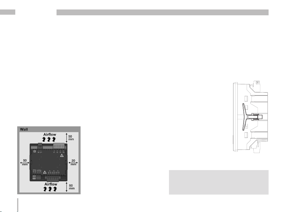
Assembly
Installation location
The UMG 96RM-M is suitable for installation in permanent, weatherproof switchboards. Conducting switchboards must be earthed.
Installation position
The UMG 96RM-M must be installed vertically in order
to achieve sufficient ventilation. The clearance to the top
and bottom must be at least 50 mm and 20 mm
at the sides.
Front panel cutout
Cutout dimensions:
+0.8
x 92
+0.8
mm.
92
Fig. UMG 96RM-M
installation location
(rear view)
12
Mounting
The UMG 96RM-M is mounted on the switchboard
by the side mounting brackets. These must be removed
before using the device. Mounting is carried out
by inserting and engaging the brackets.
Fig. UMG 96RM-M
mounting bracket (side
view)
Failure to comply with the minimum
m
spacing can destroy the UMG 96RM-M
at high ambient temperatures!
Page 13

UMG 96RM-M
13
Page 14
UMG 96RM-M
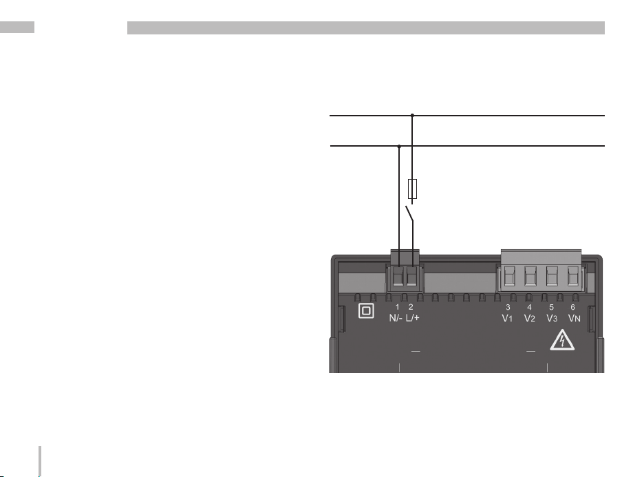
Installation
Supply voltage
A supply voltage is required to operate the UMG
96RM-M.
The voltage supply is connected via plug-in terminals
on the back of the device.
Before applying the supply voltage, ensure that
the voltage and frequency correspond with the details
on the nameplate!
The supply voltage must be connected via a UL/IEC
approved fuse (6 A, type C).
L
N
Fuse
Separator
Fig. Connection example of the supply voltage
to the UMG 96RM-M
14
Page 15

m
UMG 96RM-M
• In building installations, the supply
voltage must be provided with a
disconnect switch or circuit breaker.
• The disconnect switch must be attached
near the device and must be easily
accessible by the user.
• The switch must be labelled as a
separator for this device.
• Voltages that exceed the permissible
voltage range can destroy the device.
15
Page 16
UMG 96RM-M
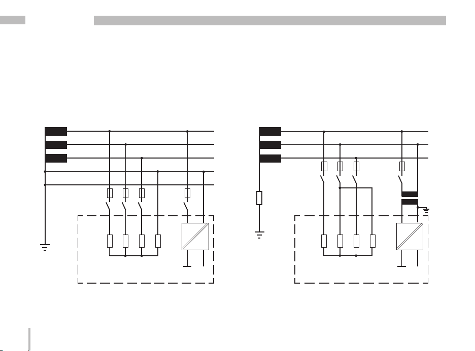
Voltage metering
The UMG 96RM-M can be used for voltage measurement
in TN, TT and IT systems.
Voltage measurement in the UMG 96RM-M is designed
for the 300 V overvoltage category CATIII (4 kV rated
pulse voltage).
L1
L2
277V/480V 50/60Hz
L3
N
PE
V1 V3V2 VN
AC/DC
4M
4M
4M
4M
DC
Measuring voltage
UMG 96RM
Auxiliary energy
Fig. Principle circuit diagram - Measurement in three-phase
4-wire systems.
16
In systems without a neutral, measured values that
require a neutral refer to a calculated neutral.
L1
L2
480V 50/60Hz
L3
Impedanz
V3V2
VN
AC/DC
4M
4M
DC
System
earthing
V1
4M
4M
Measuring voltage
UMG 96RM
Fig. Principle circuit diagram - Measurement in three-phase
Auxiliary energy
3-wire systems.
Page 17
Rated mains voltage
Lists of the networks and their rated mains voltage
in which the UMG 96RM-M can be used.
UMG 96RM-M
Three-phase 4-wire systems
with earthed neutral conductor.
U
/ U
L-N
L-L
66 V/115 V
120 V/208 V
127 V/220 V
220 V/380 V
230 V/400 V
240 V/415 V
260 V/440 V
277 V/480 V
Fig. Table of the rated mains voltages suitable
for the voltage measuring inputs according
to EN60664-1:2003.
Maximum rated voltage
of the network
Unearthed three-phase, 3-wire systems.
U
L-L
66 V
120 V
127 V
220 V
230 V
240 V
260 V
277 V
347 V
380 V
400 V
415 V
440 V
480 V
Fig. Table of the rated mains voltages suitable
for the voltage measuring inputs according
to EN60664-1:2003.
Maximum rated voltage
of the network
17
Page 18
UMG 96RM-M
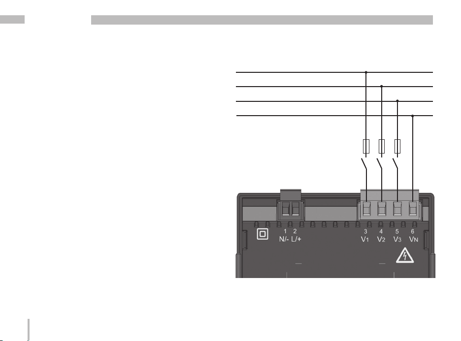
Voltage measurement inputs
The UMG 96RM-M has three voltage measurement
inputs (V1, V2, V3).
Overvoltage
The voltage measurement inputs are suitable for
measurement in networks in which overvoltages of
overvoltage category 300V CATIII (4 kV rated pulse
voltage) can occur.
Frequency
The UMG 96RM-M requires the mains frequency for
the measurement and calculation of measured values.
The UMG 96RM-M is suitable for measurements in the
frequency range of 45 to 65 Hz.
18
L1
L2
L3
N
Fuse
Separator
Fig. Connection example for the voltage measurement
Page 19

UMG 96RM-M
When connecting the voltage measurement, the following
must be observed:
• A suitable separator must be provided in order
to switch off the power to the UMG 96RM-M.
• The separator must be placed near the UMG 96RMM, marked for the user and easily accessible.
• Use a fuse protected, UL/IEC approved 10A circuit
breaker (type C) as an overcurrent protection device
and separator.
• The overcurrent protection device must have a nominal
value that is designed for the short circuit current on
the connection point.
• Measurement voltages and measurement currents
must originate from the same grid
c
c
c
Attention!
Voltages that exceed the permitted
ratedmains voltages must be connected
via voltage transformers.
Attention!
The UMG 96RM-M is not suitable for
the measurement of DC voltages.
Attention!
The voltage measurement inputs on
the UMG 96RM-M are dangerous
to touch!
19
Page 20
UMG 96RM-M
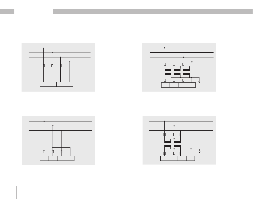
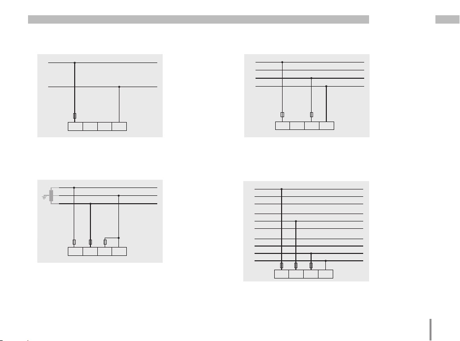
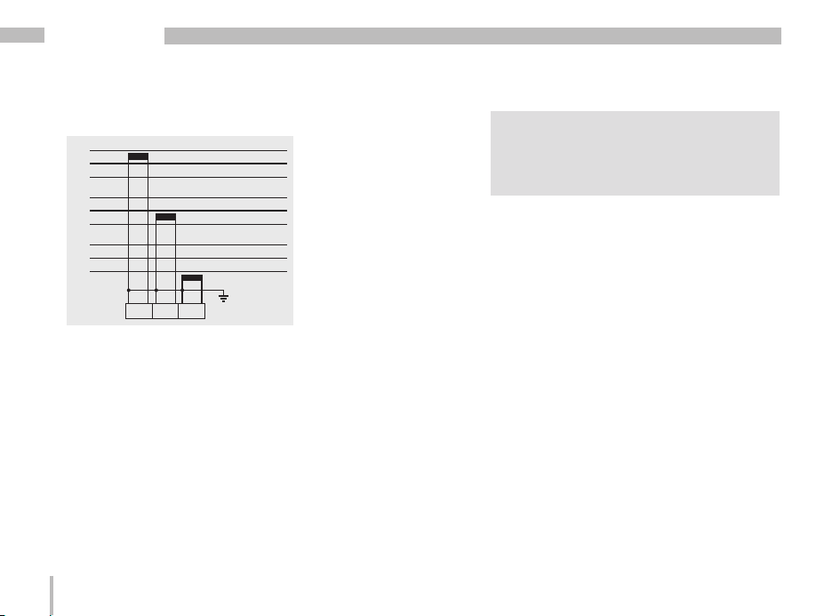
Connection diagram, voltage measurement
• 3p 4w (addr. 509= 0), factory setting
L1
L2
L3
N
V1 V2 V3 VN
Fig. System with three-phase conductors and a
neutral conductor.
• 3p 4u (addr. 509 = 2)
L1
L2
L3
V1 V2 V3 V N
Fig. System with three-phase conductors and
no neutral conductor. Measured values that require a neutral refer to a calculated neutral.
20
• 3p 4wu (addr. 509 = 1)
L1
L2
L3
N
V1 V2 V3 V N
Fig. System with three-phase conductors and
a neutral conductor. Measurement via voltage
transformer.
• 3p 2u (addr. 509 = 5)
L1
L2
L3
V1 V2 V3 V N
Fig. System with three-phase conductors and
no neutral conductor. Measurement via voltage
transformer. Measured values that require a
neutral refer to a calculated neutral.
Page 21
UMG 96RM-M
• 1p 2w1 (addr. 509 = 4)
L1
N
V1 V2 V3 V N
Fig. Measured values derived from the V2 and
V3 voltage measurement inputs are assumed to
be zero and not calculated.
• 1p 2w (addr. 509 = 6)
L1
L2
V1 V2 V3 V N
Fig. TN-C system with single-phase, three-wire
connection. Measured values derived from the
V3 voltage measurement input Zero are assumed to be zero and not calculated.
• 2p 4w (addr. 509 = 3)
L1
L2
L3
N
V1 V2 V3 V N
Fig. System with uniform phase loading. The
measured values for the V2 voltage measurement input are calculated.
• 3p 1w (addr. 509 = 7)
L1
L2
L3
L1
L2
L3
L1
L2
L3
N
V1 V2 V3 V N
Fig. Three systems with uniform phase loading.
The measurement values L2/L3 resp. L1/L3 resp.
L1/L2 of the respective system are calculated.
21
Page 22
UMG 96RM-M
Current measurement
The UMG 96RM-M is designed for connecting current transformers with secondary currents of ../1A and
../5A. The factory set current transformer ratio is 5/5 A
and may need to be adapted to the current transformers.
It is not possible to perform a direct measurement without a current transformer with the UMG 96RM-M.
Only AC currents (and not DC currents) can be measured.
c
m
c
22
Attention!
The current measurement inputs are
dangerous to touch.
Attention!
The UMG 96RM-M is not suitable for the
measurement of DC voltages.
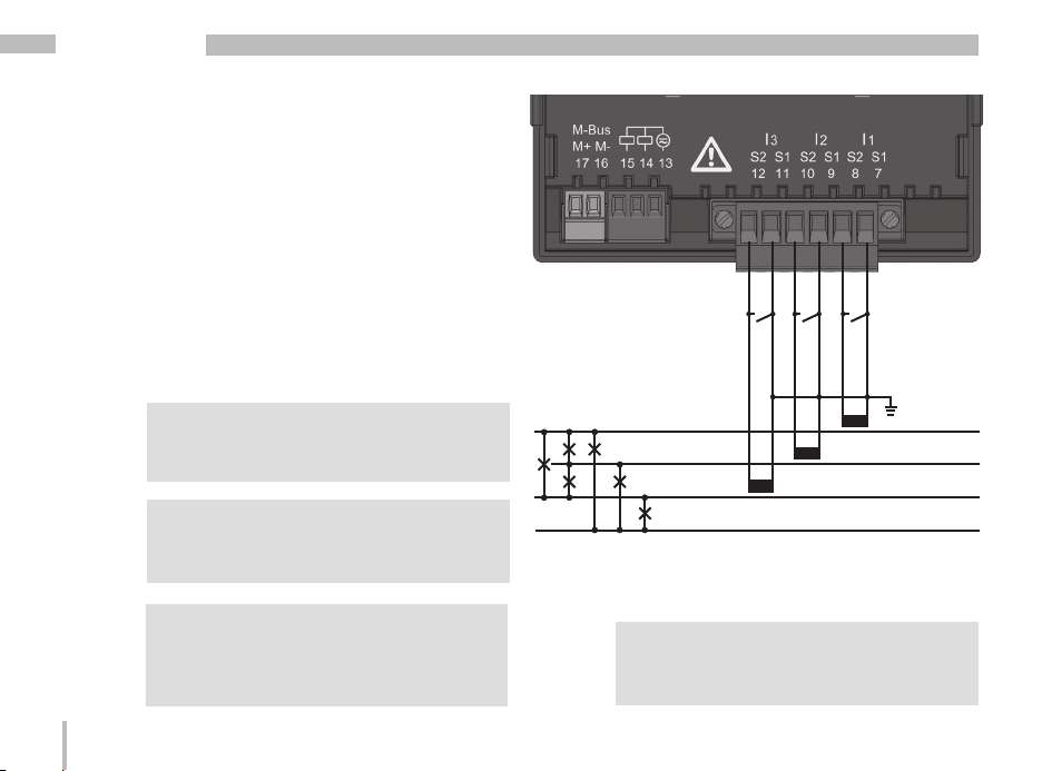
Earthing current transformers!
If a connection is provided for earthing
the secondary winding, it must be connected
to the earth.
Load
Fig. Current measurement via current transformer
(connection example)
The attached screw terminal has to be
m
fixed sufficiently with two screws on the
device!
L1
L2
L3
N
Page 23

Direction of the current
If incorrectly connected, a subsequent re-connection of
the current transformer is required.
UMG 96RM-M
c
Current transformer terminals!
The secondary terminals of the current
transformer must be short-circuited to this
before the power supply lines to the UMG
96RM-M are disconnected!
If a test switch which automatically shortcircuits the current transformer secondary
leads is available, it is sufficient to put this
into the “test” position provided the shortcircuiters have been checked beforehand.
c
Open current transformer!
High voltage peaks that are dangerous to
touch can occur on current transformers
that are operated in an open state at
the secondary terminals.
In “open-safe current transformers”, the
winding insulation is measured so that the
current transformers can operate in an open
state. However, these current transformers
are also dangerous to touch if they are
operated in an open state.
23
Page 24
UMG 96RM-M
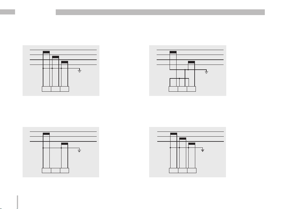
Connection diagram, current measurement
• 3p 4w (addr. 510= 0), factory setting • 3p 2i (addr. 510 = 1)
L1
L2
L3
N
L1
L2
L3
N
I1 I2 I3
Fig. Measurement in a three-phase net-work
with an unbalanced load.
• 3p 2i0 (addr. 510 = 2)
L1
L2
L3
I1 I2 I3
Fig. The measured values for the I2 current
measurementinput are calculated.
24
I1 I2 I3
Fig. System with uniform phase loading. The
measured values for the I2 current measurement
input are measured.
• 3p 3w3 (addr. 510 = 3)
L1
L2
L3
I1 I2 I3
Fig. Measurement in a three-phase net-work
with an unbalanced load.
Page 25
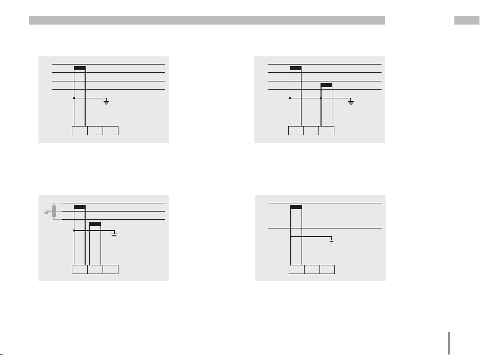
UMG 96RM-M
• 3p 3w (addr. 510 = 4)
L1
L2
L3
N
I1 I2 I3
Fig. System with uniform phase loading. The
measured values for the I2 and I3 current
measurement inputs are calculated.
• 1p 2i (addr. 510 = 6)
L1
L2
I1 I2 I3
Fig. Measured values derived from the I3 current
measurement input are assumed to be zero and
not calculated.
• 2p 4w (addr. 510 = 5)
L1
L2
L3
N
I1 I2 I3
Fig. System with uniform phase loading. The
measured values for the I2 current measurement
input are calculated.
• 1p 2w (addr. 510 = 7)
L1
N
I1 I2 I3
Fig. Measured values derived from the I2 and I3
current measurement inputs are assumed to be
zero and not calculated.
25
Page 26
UMG 96RM-M
Connection diagram, current measurement
• 3p 1w (addr. 510 = 8)
L1
L2
L3
L1
L2
L3
L1
L2
L3
I1 I2 I3
Fig. Three systems with uniform phase loading. The current measurement values of the
phases of the respective system where are no
CTs connected are calculated (I2/I3 resp. I1/I3
resp. I1/I2).
26
c
Caution!
The UMG96RM-M is only approved for
a current measurement using the current
transformer.
Page 27
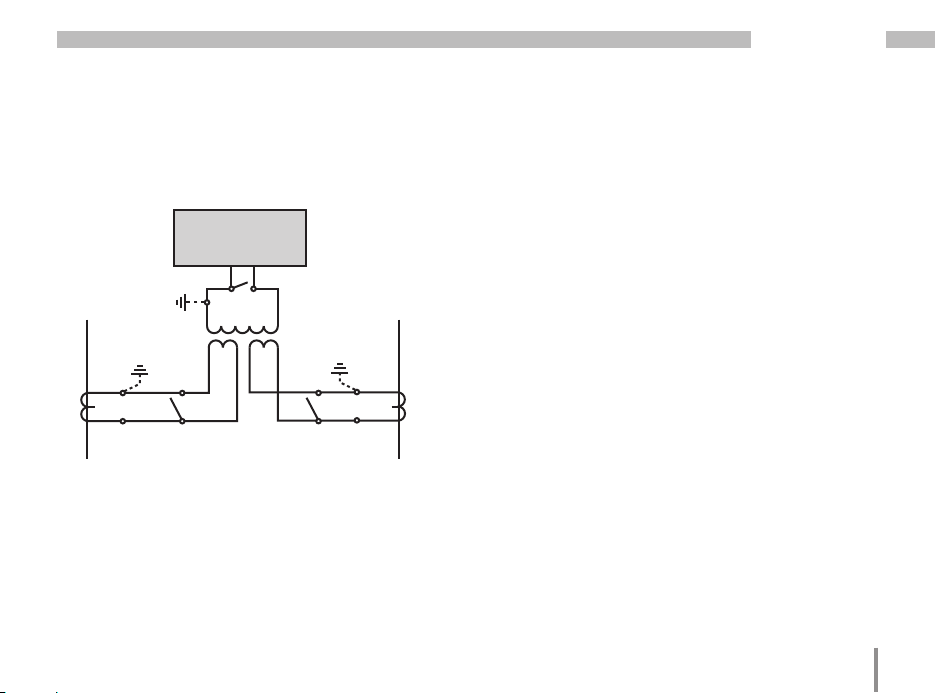
Total current measurement
UMG 96RM-M
If the current measurement takes place via two current
transformers, the total transformer ratio of the current
transformer must be programmed in the UMG 96RM-M.
UMG
I
S
S2
1
Einspeisung 1
Supply 1
1P1
(K)
(L)
1P2
Verbraucher A
Consumer A
1S1
1S
P1
1S1 1S2 2S1 2S2
(k)
(l)
2
P2
Einspeisung 2
Supply 2
2S1
(k)
(l)
2S2
Verbraucher B
Consumer B
2P
(K)
(L)
2P2
1
Fig. Current measurement via a total current transformer
(example).
Example: The current measurement takes place via two
current transformers. Both current transformers have
a transformer ratio of 1000/5 A. The total measurement
is performed with a 5+5/5 A total current transformer.
The UMG 96RM must then be set as follows:
Primary current: 1000 A + 1000 A = 2000 A
Secondary current: 5 A
27
Page 28
UMG 96RM-M
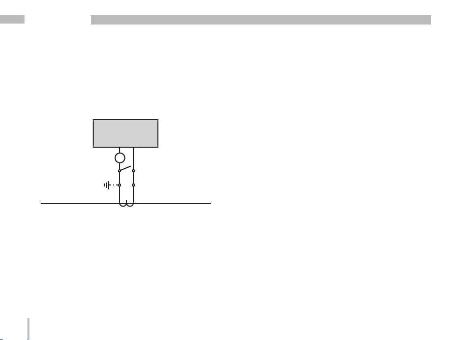
Ammeter
If you want to measure the current not only with the UMG
96RM-M but also with the ammeter, the ammeter must
be connected in series with the UMG 96RM-M.
UMG
I
S2
1
S
A
Einspeisung
Supply
(k)S
1 S2(l)
2(L)(K)P1
P
Verbraucher
Fig. Current measurement with an additional
ammeter (example).
28
Consumer
Page 29
UMG 96RM-M
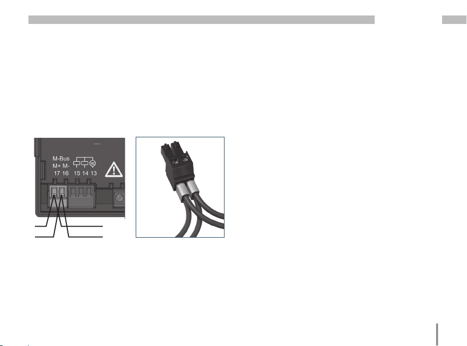
M-Bus interface
The M-Bus interface is designed with the UMG 96RM-M
as a 2-pole plug contact and communicates via the MBus protocol.
The UMG 96RM-M loads the M-Bus with an M-Bus device load of 1.5 mA.
M+
M-
M-Bus interface,
2-pole plug contact
2-pin connector with cable
connection ( cable type: 2 x
2
0.75 mm
) via twin ferrules
Cable connections
Twisted screened cable should be used for connections
via the M-Bus interface.
• Cable paths should be designed to be as short as
possible.
• Maintain as much distance as possible to power cables and to consumers (e.g. electrical motors, neon
tubes, transformers).
• In order to prevent cross currents in the bus, there
should be no ground coupling, or a maximum of one
instance of ground coupling.
• Gather the cables mechanically above the earthing
clamp in order to avoid damage due to cable movements.
• Use suitable cable glands to feed the cables into the
cabinet - for example armoured conduit couplings.
29
Page 30

UMG 96RM-M
Cable type
The cable used must be suitable for an ambient
temperature of at least 80 °C.
Use 2-core, twisted, screened cable wherever possible
for optimum data transmission.
Recommended cable types:
Unitronic LIYCY 4x0.75
30
Bus structure
• All devices are connected in a star, line or tree structure, whereby each device has its own address within
the bus (see also Parameter programming).
• A subdivision of the network structure into individual
segments is implemented via repeaters (line amplifiers).
• Up to 250 subscribers can be connected together in
a single segment. However, the characteristics of the
Master device are the defining factors here.
• If the master is replaced, the bus is out of service.
• Devices can be replaced without the bus being unstable.
Star structure
• Each measurement device is linked directly to the
M-Bus Master. Faults in the bus system are localised
faster by switching the individual devices on and off.
Line structure
• The connection of the measurement devices is sequential, in a line. With this possible faults in the bus
system may arise due to the voltage drop. Faults
within the system are harder to localise in this cheaper
structure.
Page 31
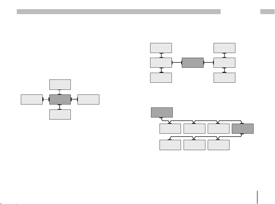
Tree structure
• This topology combines the star and line structures.
Repeaters generally divide the branches into individual segments. Thus in the event of a fault only a specific
branch is affected and so a fault in the bus system can
be quickly localised.
Slave
(device)
Slave
(device)
Master
(control)
Slave
(device)
Slave
(device)
UMG 96RM-M
Slave
(device)
Slave
(device)
Slave
(device)
Master
(Zentrale)
Illustration of bus type: Tree structure
Master
(control)
Slave
(device)
Slave
(device)
Slave
(device)
Illustration of bus type: Star structure
Slave
(device)
Slave
(device)
Slave
(device)
Slave
(device)
Slave
(device)
Slave
(device)
Illustration of bus type: Line structure
Repeater
31
Page 32

UMG 96RM-M
Digital outputs
The UMG 96RM-M has 2 digital outputs. These outputs
are electrically isolated from the evaluation electronics
by optocouplers. The digital outputs have a common
reference.
• The digital outputs can switch DC and AC loads.
• The digital outputs are not short circuit protected.
• Connected cables longer than 30 m must be shielded.
• An external auxiliary voltage is required.
• The digital outputs can be used as pulse outputs.
• The digital outputs can output results from
comparators.
Fig. Connection of digital/pulse
outputs
~
32
External
auxiliary voltage
UMG 96RM-M
Digital outputs 1-2
Digital outputs 1-2
13
Digital
output 1
Digital
output 2
Abb. Anschluss von zwei Relais an die digitalen Ausgänge 14 und 15.
C
When using the digital outputs as a pulse
output, the auxiliary voltage (DC) must only
have a maximum residual ripple of 5%.
14
15
AC/DC
AC/DC
24 V
AC/DC
~~
K1 K2
Page 33

UMG 96RM-M
33
Page 34

UMG 96RM-M
Operation
The UMG 96RM-M is operated using buttons 1 and
2. Measured values and programming data appears
on a liquid crystal display.
A distinction is made between display mode and pro-
gramming mode. The accidental changing of programming data is prevented by the entry of a password.
Display mode
In the display mode, you can scroll between
the programmed measured value displays using
buttons 1 and 2. All factory-set measured value displays
listed in section 1 can be called up. Up to three measured
values are displayed per measured value display.
The measured value relaying allows select measured
value displays to be shown alternately after a settable
changeover time.
Programming mode
In the programming mode, the settings required
for operating the UMG 96RM-M can be displayed
and changed. Pressing buttons 1 and 2 simultaneously
for about one second calls up the programming mode
after the password prompt. If no user password was
34
programmed, the user arrives directly in the first
programming menu. Programming mode is indicated
by the text “PRG” on the display.
Button 2 can now be used to switch between
the following programming menus:
- current transformer,
- voltage transformer,
- parameter list.
If the device is in programming mode and no button has
been pressed for approximately 60 seconds or if buttons
1 and 2 are pressed simultaneously for approx. one second, the UMG 96RM-M returns to display mode.
Page 35

Export
Mean value
Programming
mode
Sum measurement
Phase conductorPhase conductor
Password
CT: Current
transformer
VT: Voltage
transformer
K1: Output 1
K2: Output 2
Button 2
Button 1
UMG 96RM-M
35
Page 36

UMG 96RM-M
Parameters and measured values
All parameters necessary for operating the UMG 96RMM, e.g. the current transformer data, and a selection of
frequently required measured values are stored in the
table.
The contents of most addresses can be accessed via the
serial interface and the buttons on the UMG 96RM-M.
Only the first 3 significant digits of a value can be entered
on the device.
The device always only displays the first 3 significant
digits of a value.
Selected measured values are summarised in measured
value display profiles and can be shown in display mode
using buttons 1 and 2.
36
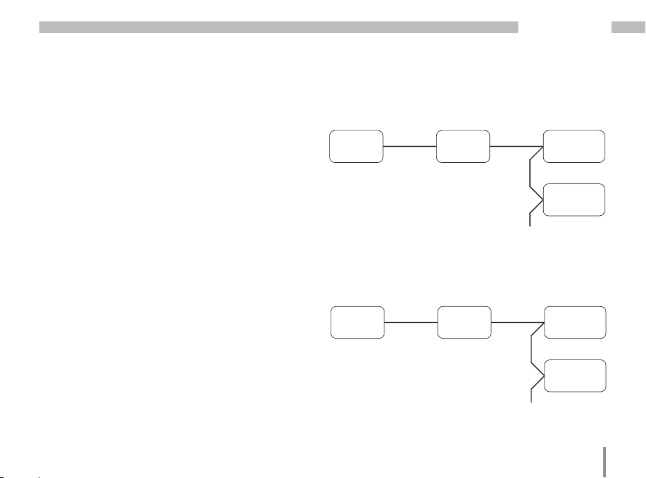
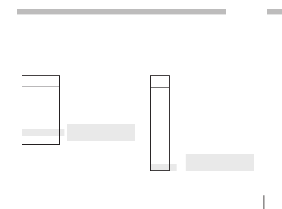
Example of the parameter display
On the UMG 96RM-M display
the value “001” is shown as
the content of address “000”.
This parameter reflects the
device address (here “001”)
of the UMG 96RM on a bus
in list form.
Example of the measured
value display
In this example, the UMG
96RM-M display shows the
voltages L to N with 230 V
each.
The K1 and K2 transistor outputs are conductive and current can flow.
Page 37

Button functions
UMG 96RM-M
Display mode
Change mode
simultaneous
Browse
short
long
Measured
values 1a
Measured
values 2a
long short
Measured
values 2b
Password
Programming
menu 1
(flashes)
Programming mode
short
long
(flashes)
Change mode
simultaneous
Browse
Programming
menu 1
Programming
menu 2
Programming
menu 3
Programming
Confirm selection
Short: digit +1
Long: digit -1
Short: value x 10
(decimal to the right)
Long: Value /10
(decimal to the left)
37
Page 38

UMG 96RM-M
Configuration
Applying the supply voltage
To configure the UMG 96RM-M, the supply voltage must
be connected.
The level of supply voltage for the UMG 96RM-M can
be found on the nameplate.
If no display appears, check the operating voltage
to determine whether it is within the rated voltage range.
Current and voltage transformers
A current transformer is set to 5/5 A in the factory.
The pre-programmed voltage transformer ratio only
needs to be changed if voltage transformers are
connected.
When connecting voltage transformers, the measurement voltage on the UMG 96RM-M nameplate must be
observed!
38
c
C
m
Attention!
Supply voltages that do not correspond
to the nameplate information can lead
to device malfunction or destruction.
The adjustable value 0 for the primary
current transformer does not produce
any useful energy values and must not
be used.
Devices, which are programmed to automatic frequency detection, need approximately 20 seconds to detect grid
frequency. During this period, the measured values do not keep the confirmed
measuring accuracy.
Page 39

UMG 96RM-M
Programming current transformers
Switching to programming mode
• Simultaneously press buttons 1 and 2 in order
to switch to programming mode. If a user password
was programmed, the password request will appear
with "000". The first digit of the user password flashes
and can be changed with button 2. The next digit is
selected by pressing button 2 and will begin flashing.
If the correct combination was entered or if no user
password was programmed, the device will enter programming mode.
• The symbols for the programming mode (PRG) and for
the current transformer (CT) appear.
• Confirm the selection with button 1.
• The first digit of the input area for the primary current
starts flashing.
Current transformer primary current input
• Change the flashing digit with button 2.
• Select the next digit to be changed with button 1.
The selected digit to be changed starts flashing.
If the entire number is flashing, the decimal point can
be moved with button 2.
Current transformer secondary current input
• Only 1 A or 5 A can be set as the secondary current.
• Select the secondary current with button 1.
• Change the flashing digit with button 2.
Leaving programming mode
• Simultaneously press buttons 1 and 2 to exit the programming mode.
39
Page 40

UMG 96RM-M
Programming voltage transformers
• Switch to the programming mode as described. The
symbols for the programming mode (PRG) and for the
current transformer (CT) appear.
• Use button 2 to switch to the voltage transformer
setting.
• Confirm the selection with button 1.
• The first digit of the input area for the primary current
starts flashing. The ratio of primary to secondary
voltage of the voltage transformer can be set in the
same way as the assignment of the current transformer
ratio of primary to secondary current.
40
Current transformer, primary
Programming mode
Units display
Current transformer, secondary
Current transformer symbol
Voltage transformer, primary
Programming mode
Units display
Voltage transformer,
secondary
Voltage transformer,
symbol
Page 41

UMG 96RM-M
Programming parameters
Switching to programming mode
• Switch to the programming mode as described. The
symbols for the programming mode (PRG) and for the
current transformer (CT) appear.
• Use button 2 to switch to the voltage transformer
setting. The first parameter of the parameter list
is shown by repeatedly pressing button 2.
Changing parameters
• Confirm the selection with button 1.
• The most recently selected address is displayed with
the associated value.
• The first digit of the address flashes and can be
changed using button 2. Button 1 provides a selection
of digits that, in turn, can be changed with button 2.
Changing the value
• Once the desired address is set, a digit of the value
is selected with button 1 and changed with button 2.
Leaving programming mode
• Simultaneously press buttons 1 and 2 to exit the
programming mode.
Fig. Password request
If a password was set,
it can be entered using
buttons 1 and 2.
Fig. Current transformer
programming mode
The primary and
secondary currents can
be changed using buttons
1 and 2 (cf. page 39).
Fig. Programming mode
Voltage transformer
The primary and
secondary currents can
be changed using buttons
1 and 2 (cf. page 40).
Fig. Programming mode
Parameter display
The individual parameters
can be changed
using buttons 1 and 2
(cf. page 36).
41
Page 42

UMG 96RM-M
Device address (addr. 000)
If several devices are connected to one another
via the M-Bus interface, a master device can only
differentiate between these devices by means of their
device addresses. Therefore, each device in a network
must have a different device address. Addresses can be
set in the range from 1 to 250.
The adjustable range of the device
C
Secondary device address (addr. 081-084)
The secondary address provides - in addition to the primary address - a further opportunity to speak directly to
the device within the bus system.
The composition of the secondary address is broken
down into a device-specific section and an extended
section:
• The secondary address is comprised of 8 Bytes and
is coded as BCD.
• The extended section of the secondary address is
42
address is between 0 and 255. The values
0 and 251 to 255 are reserved and may
not be used.
pre-assigned with the device serial number. This section can be changed by the customer (addr. 081- 084).
• The device-specific section of the secondary address
cannot be changed.
Extended section, 8 digits
Device-specific section,
XX XX XX XX 2E 28 09 02
8 digits
Version, 2 digits
Internal release, 2 digits
Manufacturer ID, 4 digits
Extended section, 4th part
Extended section, 3rd part
Extended section, 2nd part
Extended section, 1st part
Page 43

UMG 96RM-M
Baud rate (addr. 001)
A common baud rate is adjustable for the M-Bus interfaces. The baud rate must be chosen to be a uniform
value in the network. The parameter data bits (8), parity
(even) and stop bits (1) are permanently set.
Setting Baud rate
0 300 Baud
1 600 Baud
2 1200 Baud
3 2400 Baud
4 4800 Baud
5 9600 Baud
6 19200 Baud
7 38400 Baud
Mean value
Mean values are formed over an adjustable period
for the current, voltage and power measured values.
The mean values are identified with a bar above
the measured value.
The averaging time can be selected from a list of nine
fixed averaging times.
Current averaging time (addr. 040)
Power averaging time (addr. 041)
Voltage averaging time (addr. 042)
Setting Averaging time/sec.
0 5
1 10
2 15
3 30
4 60
5 300
6 480 (factory setting)
7 600
8 900
43
Page 44

UMG 96RM-M
Averaging method
After the set averaging time, the exponential averaging
method used achieves at least 95% of the measured
value.
44
Minimum and maximum values
All measured values are measured and calculated every
10/12 periods. Minimum and maximum values are determined for most of the measured values.
The minimum value is the smallest measured value that
has been determined since the last reset. The maximum value is the largest measured value that has been
determined since the last clearance. All minimum and
maximum values are compared with the corresponding
measured values and are overwritten if they are undercut
or exceeded.
The minimum and maximum values are stored in an EEPROM every 5 minutes, without the date and time. This
means that if the operating voltage fails, only the minimum and maximum values of the last 5 minutes are lost.
Clearing minimum and maximum values (addr. 506)
If "001" is written to the address 506, all minimum
and maximum values are simultaneously cleared.
The maximum value of the current mean value
is an exception. The maximum value of the current mean
value can also be cleared directly in the display menu
by pressing and holding button 2.
Page 45

Mains frequency (addr. 034)
UMG 96RM-M
For automatic ascertainment of the mains frequency, an
L1-N voltage larger than 10Veff must be applied to the
voltage measurement input V1.
The mains frequency is then used to calculate the
sampling rate for the current and voltage inputs.
If there is no measurement voltage, the mains frequency
cannot be determined and thus no sampling rate can be
calculated. The acknowledgeable error message “500”
appears.
The voltage, current and all other resulting values
are calculated based on the previous frequency
measurement and possible cable-connecting sockets
and continue to be displayed. However, these derived
measured values are no longer subject to the specified
accuracy.
If it is possible to re-measure the frequency, then the
error message will disappear automatically after a
period of approx. 5 seconds once the voltage has been
restored.
The error is not displayed if a fixed frequency has been
configured.
Adjustment range: 0, 45 .. 65
0 = automatic frequency determination.
The mains frequency is determined from
the measurement voltage.
45..65 = fixed frequency
The mains frequency is preselected.
45
Page 46

UMG 96RM-M
Energy meter
The UMG 96RM-M has energy meters for active energy,
reactive energy and apparent energy.
46
Reading the active energy
Total active energy
The active energy in this
example is: 12 345 678 kWh
The active energy in this
example is: 134 178 kWh
Page 47

UMG 96RM-M
TH
fund
TH
fund
Harmonics
Harmonics are the integer multiple of a mains frequency.
The voltage mains frequency for the UMG 96RM-M must
be in the range between 45 and 65 Hz. The calculated
voltage and current harmonics refer to this mains
frequency.
Harmonics up to 40x the mains frequency are recorded.
The harmonics for currents are given in amperes
and the harmonics for voltages are given in volts.
Number of the harmonic
Phase L3
Current harmonic
Value
Fig. Display of the 15th harmonic of the current
in the L3 phase (example).
Harmonics are not displayed in the factory
default setting.
C
Total Harmonic Distortion (THD)
THD is the ratio of the root mean square value of
harmonics to the root mean square value of the mains
frequency.
Total Harmonic Distortion of the current (THDI):
M
1
D
=
I
∑
I
n
2
I
.
nHarm
2
=
Total Harmonic Distortion of the voltage (THDU):
M
1
D
=
U
∑
U
n
=
2
U
.
nHarm
2
Phase L3
Voltage
Value
Fig. Display of the total harmonic distortion
of the voltage from the L3 phase (example).
47
Page 48

UMG 96RM-M
Measured value relay
All measured values are calculated every 10/12 periods
and can be recalled once per second on the measured
value displays. Two methods are available for retrieving
the measured value displays:
• The automatically changing display of selected
measured values, referred to here as measured value
relaying.
• Selection of a measured value display using buttons
1 and 2 from a preselected display profile.
Both methods are simultaneously available. Measured
value relaying is active if at least one measured value
display is programmed with a changeover time greater
than 0 seconds.
If a button is pressed, the measured value displays
of the selected display profile can be browsed. If no
button is pressed for about 60 seconds, the device
switches to the measured value relay and the measured
values from the selected display change profile
of the programmed measured value displays are shown
one after the other.
48
Changeover time (addr. 039)
Adjustment range: 0 .. 60 seconds
If 0 seconds are set, no changeover takes place between
the measured value displays selected for the measured
value relay.
The changeover time applies for all display change
profiles.
Display change profile (addr. 038)
Adjustment range: 0 .. 3
0 - Display changeover profile 1, by default.
1 - Display changeover profile 2, by default.
2 - Display changeover profile 3, by default.
Page 49

UMG 96RM-M
Measured value displays
After return of the power supply, the UMG 96RM-M
shows the first measured value panel from the current
display profile. In order to keep the selection of measured values to be displayed arranged in a clear manner,
only one part of the available measured values is preprogrammed for recall in the measured value display by
default. A different display profile can be selected if other
measured values are required to be shown on the UMG
96RM-M display.
Display profile (addr. 037)
Adjustment range: 0 .. 3
0 - Display profile 1, default setting.
1 - Display profile 2, default setting.
2 - Display profile 3, default setting.
User password (addr. 050)
A user password can be programmed in order to impede
any accidental change to programming data. A switch
to the next programming menu can only be made after
entering the correct user password.
No user password is specified in the factory. In this
case, the password menu is skipped and the current
transformer menu is reached directly.
If a user password was programmed, the password
menu will appear with the display “000”.
The first digit of the user password flashes and can
be changed with button 2. The next digit is selected
by pressing button 1 and will begin flashing.
The programming menu for the current transformer can
only be accessed after entering the correct number
combination.
49
Page 50

UMG 96RM-M
Clear energy meter (addr. 507)
The active, apparent and reactive energy meters can
only be cleared together.
Address 507 must be written with "001" in order to clear
the contents of the energy meters.
Clearing the energy meters means this
C
50
data in the device is gone.
In order to avoid possible data loss,
read and save the measured values with
the GridVis software before clearing.
Rotation field direction
The rotation field direction of the voltages and the
frequency of phase L1 are shown on the display.
The rotation field direction indicates the phase sequence
in three-phase systems. Usually there is a "clockwise
spinning rotation field".
The phase sequence at the voltage measurement
inputs is checked and displayed in the UMG 96RM-M.
A movement of the character string in the clockwise
direction means a "right rotation" and a counterclockwise movement indicates a "left rotation".
The rotation field direction is determined only if
the measurement and operating voltage inputs are fully
connected. If one phase is missing or two of the same
phases are connected, the rotation field direction will not
be determined and the character string does not appear
on the display.
Fig. Display of the mains
frequency (50.0) and the
rotation field direction
Fig. No rotation field
direction detectable.
Page 51

UMG 96RM-M
LCD contrast (addr. 035)
The preferred direction of viewing for the LCD is from
"below". The user can adjust the LCD contrast of the
LCD screen. It is possible to set the contrast in the range
from 0 to 9 in steps of 1.
0 = characters are very light
9 = characters are very dark
Factory default setting: 5
Backlight
The LCD backlight allows the display to be read easily
even in poor light. The brightness can be controlled by
the user in stages from 0 to 9.
The UMG 96RM has two different types of backlight:
- the operation backlight
- the standby backlight
Operation backlight (addr. 036)
The operation backlight is activated by pushing the appropriate button, or with a restart.
Standby backlight (addr. 747)
This backlight is activated after an adjustable period of
time (addr. 746). If no button is pressed within this period, then the device switches to the standby backlight.
If buttons 1 - 3 are pressed, the device switches to
the operation backlight and the defined period of time
begins again.
If the brightness settings for the two backlights are set to
the same value, then no change is discernible between
the operation and standby backlights.
Addr. Description Setting
036 Brightness for
operation backlight
746 Period of time after
which the backlight will
switch to standby
747 Brightness for
standby backlight
0 = min. brightness, 9 = max. brightness
range
0 .. 9 6
60 .. 9999
Sek.
0 .. 9 0
Default
setting
900
Sek.
51
Page 52

UMG 96RM-M
Time recording
The UMG 96RM-M records the operating hours and the
total running time of each comparator
• where the time of operating hours is measured with
a resolution of 0.1 h and is displayed in hours or
• the total running time of the comparator is represented
in seconds (when 999999 seconds is reached,
the display changes to hours).
For the querying of measured value displays, the times
are marked with the numbers 1 to 6:
none = operating hours meter
1 = total running time, comparator 1A
2 = total running time, comparator 2A
3 = total running time, comparator 1B
4 = total running time, comparator 2B
5 = total running time, comparator 1C
6 = total running time, comparator 2C
A maximum of 99999.9 h (= 11.4 years) can be shown
on the measured value display.
52
Operating hours meter
The operating hours meter measures the time for which
the UMG 96RM-M records and displays measured
values.
The time of operating hours is measured with a resolution
of 0.1 h and is displayed in hours. The operating hours
meter cannot be reset.
Total running time of the comparator
The total running time of a comparator is the sum
of all time for which there is a limit value violation
in the comparator result.
The total running time of the comparator can only
be reset via the GridVis software. The reset is carried out
for all total running times.
Fig. Operating hours meter of
the measured value display
The UMG 96RM-M shows the
number 140.8 h in the operating hours meter. This corresponds to 140 hours and
80 industrial minutes. 100 industrial minutes correspond
to 60 minutes. In this example,
80 industrial minutes therefore
represent 48 minutes.
Page 53

Serial number (addr. 754)
The serial number shown by UMG 96RM-M has 6 digits
and is part of the serial number displayed on the nameplate.
The serial number cannot be changed.
Serial number display
Serial number
information
on the nameplate:
XX00-0000
Software release (addr. 750)
The software for UMG 96RM is continuously improved
and expanded. The software version in the device is
marked with a 3-digit number, the software release.
The user cannot change the software release.
UMG 96RM-M
53
Page 54

UMG 96RM-M
Commissioning
Applying the supply voltage
• The level of supply voltage for the UMG 96RM-M can
be found on the nameplate.
• After applying the supply voltage, the UMG 96RM-M
switches to the first measured value display.
• If no display appears, the supply voltage must
be checked to determine whether it is in the rated
voltage range.
Applying the measured voltage
• Voltage measurements in networks with rated voltages
above 300V AC to ground must be connected to a
voltage transformer.
• After the measured voltages are connected, the
measured values for the L-N and L-L voltages
displayed by the UMG 96RM-M must match those at
the voltage measurement input.
Attention!
m
54
Voltages and currents outside the permissible metering range can result in personal
injury and damage to the device.
Applying the measured current
The UMG 96RM-M is designed for connecting ../1 A
and ../5 A current transformers.
Only AC currents and not DC currents can be measured
via the current measurement inputs.
Short circuit all current transformer outputs except
for one. Compare the currents displayed on the UMG
96RM-M with the applied current.
The current displayed by the UMG 96RM-M must match
the input current, taking the current transformer ratio into
consideration.
In the short circuit current measurement inputs,
the UMG-M 96RM must show approx. zero amperes.
The factory-set current transformer ratio is 5/5 A and may
need to be adapted to the current transformer used.
Attention!
m
m
Supply voltages that do not correspond
to the nameplate information can lead
to device malfunction or destruction.
Attention!
The UMG 96RM-M is not suitable for the
measurement of DC voltages.
Page 55

UMG 96RM-M
Rotation field direction
Check the direction of the voltage rotation field on the
measured value display of the UMG 96RM-M.
Usually there is a "clockwise" spinning rotation field.
Checking the phase assignment
The assignment of the phase conductor to the current
transformer is correct if a current transformer is short
circuited at the secondary terminals and the current
shown by the UMG 96RM-M in the corresponding phase
sinks to 0A.
Checking the power measurement
Short circuit all current transformer outputs except for
one and check the displayed power.
The UMG 96RM-M must only show one rating in the
phase with the non-short-circuited current transformer
input. If this does not apply, check the measured voltage
connection and the measured current connection.
If the magnitude of the real power is correct but the sign
of the real power is negative, this can be due to two
causes:
• The connections S1 (k) and S2 (I) on the current
transformer are inverted.
• Active energy is being returned to the network.
Checking the measurement
If all voltage and current measurement inputs are
correctly connected, the individual and sum power
ratings are accurately calculated and displayed.
Checking the individual power ratings
If the current transformer is assigned to the wrong
phase conductor, the associated power rating will be
incorrectly measured and displayed.
The assignment of the phase conductor to the current
transformer on the UMG 96RM-M is correct if there
is no voltage between the phase conductor and the
associated current transformer (primary).
In order to ensure that a phase conductor on the voltage
measurement input is assigned to the correct current
transformer, the respective current transformer can be
short-circuited at the secondary terminals. The apparent
power shown by the UMG 96RM-M must then be zero
in this phase.
If the apparent power is correctly displayed but the real
power is shown with a "-" sign, the current transformer
terminals are inverted or power is being fed to the power
company.
55
Page 56

UMG 96RM-M
Check the sum power ratings
If all voltages, currents and power ratings for the
respective phase conductor are correctly displayed, the
sum power ratings measured by the UMG 96RM-M must
also be correct. For confirmation, the sum power ratings
measured by the UMG 96RM-M should be compared
with the energy of the active and reactive power meters
at the power feed.
56
Page 57

UMG 96RM-M
M-Bus interface
The data of the parameter list and measurement values
list can be accessed via the M-Bus interface with the
help of the primary or secondary address. Changing
these values is not possible via the M-Bus.
The primary device address is factory preset to „1“.
The extended section of the 8-Byte long secondary
address is factory preset to contain the device serial
number and can be individually changed via the corresponding parameters. The device-specific section of the
secondary address cannot be adjusted (see page 42).
M-Bus device features
• Addressing possible via primary address and secondary address (0 .. 250)
• Freely selectable number of data points (0 .. 27)
• Supports protocol types:
SND_NKE/$E5 and REQ_UD2/RSP_UD2
• Slave search: Search on M-Bus
The UMG 96RM-M loads the M-Bus with
C
an M-Bus device load of 1.5 mA.
Number of data points
The number of data points to be transmitted for the
RSP_UD2 telegram is defined via this address.
Address: 080
Meaning: Number of data points for RSP_UD2
Setting range: 0 .. 27
Default setting: 0 (0 = All data points)
In order to call up all data points (0), a telegram must
be sent.
Example: Read out data points 1 to 6
Set the parameter of the address to 6. With each request
all data points up to and including data point 6 will be
transmitted.
Example: Read only data point 10
Set the parameter of the address to 10. With each request all data points up to and including data point 10
will be transmitted. Use only the data point required and
ignore those that are not required.
57
Page 58

UMG 96RM-M
Measurement signal level
The data transfer in the M-Bus network is implemented
through modulation of the supply voltage, whereby the
voltage for a high signal is 36 V and 24 V for a low signal.
The slave device answers the master via the modulation
of its current draw, whereby the high signal is 1.5 mA and
the low signal is 11-20 mA.
Signal Voltage Reply current
High-Signal 36 V 1.5 mA
Low-Signal 24 V 11-20 mA
58
Structure of the RSP_UD2 telegram
Byte 1 2 3 4 5 6
Name Start Length Length Start C A
Cont. 68 68 8
Byte 7 8 9 10 11 12
Name CI ID1 ID2 ID3 ID4 MAN1
Cont. 72 46
Byte 13 14 15 16 17 18
Name MAN2 GEN MED TC Status SIG1
Cont. 40 8 2 0 0
Byte 19 20 ... ... N-1 N
Name SIG2 DIF Data Data SC Stop
Cont. 0 16
Page 59

UMG 96RM-M
List of data points
Data
Discription Unit Resolut. Device Format
point
1 Real energy, without backstop dev. Wh 10 0 6
2 Real energy, obtained Wh 10 0 6
3 Real energy, supplied Wh 10 0 6
4 Reactive energy, inductive varh 10 1 6
5 Reactive energy, capacitive varh 10 1 6
6 Reac. energy, without backst. dev. varh 10 1 6
7 Apparent energy VAh 10 2 6
8 Runtime comparator 1a sek 1 1 4
9 Runtime comparator 1b sek 1 2 4
10 Runtime comparator 1c sek 1 3 4
11 Runtime comparator 2a sek 1 4 4
12 Runtime comparator 2b sek 1 5 4
13 Runtime comparator 2c sek 1 6 4
14 Operating hours counter sek 1 0 4
15 I_sum mA 1 4 4
16 P_sum W 1 5 4
17 Q_sum, mains frequency var 1 6 4
18 S_sum VA 1 7 4
Byte
59
Page 60

UMG 96RM-M
List of data points
Data
Discription Unit Resolut. Device Format
point
19 Uln - Phase L1 mV 100 1 4
20 Uln - Phase L2 mV 100 2 4
21 Uln - Phase L3 mV 100 3 4
22 I - Phase L1 mA 1 1 4
23 I - Phase L2 mA 1 2 4
24 I - Phase L3 mA 1 3 4
25 P - Phase L1 W 1 1 4
26 P - Phase L2 W 1 2 4
27 P - Phase L3 W 1 3 4
Byte
60
Page 61

Telegramm
UMG 96RM-M
Data
point
Discription DIF DIFE DIFE DIFE VIF VIFE
1 Real energy,
without backstop dev.
2 Real energy, obtained 0x86 0x10 X X 0x04 X
3 Real energy, supplied 0x86 0x20 X X 0x04 X
4 Reactive energy, inductive 0x86 0x40 X X 0x04 X
5 Reactive energy, capacitive 0x86 0x50 X X 0x04 X
6 Reac. energy,
without backst. dev
7 Apparent energy 0x86 0x80 0x40 X 0x04 X
8 Runtime comparator 1a 0x84 0x40 X X 0x24 X
9 Runtime comparator 1b 0x84 0x80 0x40 X 0x24 X
10 Runtime comparator 1c 0x84 0xC0 0x40 X 0x24 X
11 Runtime comparator 2a 0x84 0x80 0x80 0x40 0x24 X
12 Runtime comparator 2b 0x84 0xC0 0x80 0x40 0x24 X
13 Runtime comparator 2c 0x84 0x80 0xC0 0x40 0x24 X
14 Operating hours counter 0x04 X X X 0x24 X
15 I_sum 0x84 0x80 0x80 0x40 0xFD 0x59
16 P_sum 0x84 0xC0 0x80 0x40 0x2B X
17 Q_sum
mains frequency
18 S_sum 0x84 0xC0 0xC0 0x40 0x2B X
0x06 X X X 0x04 X
0x86 0x60 X X 0x04 X
0x84 0x80 0xC0 0x40 0x2B X
61
Page 62

UMG 96RM-M
Telegram
Data
point
(X - no value available)
Discription DIF DIFE DIFE DIFE VIF VIFE
19 Uln - Phase L1 0x84 0x40 X X 0xFD 0x48
20 Uln - Phase L2 0x84 0x80 0x40 X 0xFD 0x48
21 Uln - Phase L3 0x84 0xC0 0x40 X 0xFD 0x48
22 I - Phase L1 0x84 0x40 X X 0xFD 0x59
23 I - Phase L2 0x84 0x80 0x40 X 0xFD 0x59
24 I - Phase L3 0x84 0xC0 0x40 X 0xFD 0x59
25 P - Phase L1 0x84 0x40 X X 0x2B X
26 P - Phase L2 0x84 0x80 0x40 X 0x2B X
27 P - Phase L3 0x84 0xC0 0x40 X 0x2B X
62
Page 63

M-Bus test
Data string M-Bus
$68$F7$F7$68$08$01$72$37$21$10$57$2E$28$09$02$02$00
$00$00$06$04$7E$18$00$00$00$00$86$10$04$7E$18$00$00
$00$00$86$20$04$00$00$00$00$00$00$86$40$04$28$00$00
$00$00$00$86$50$04$00$00$00$00$00$00$86$60$04$28$00
$00$00$00$00$86$80$40$04$92$18$00$00$00$00$84$40$24
$00$00$00$00$84$80$40$24$00$00$00$00$84$C0$40$24$00
$00$00$00$84$80$80$40$24$00$00$00$00$84$C0$80$40$24
$00$00$00$00$84$80$C0$40$24$00$00$00$00$04$24$FA$4F
$00$00$84$80$80$40$FD$59$00$00$00$00$84$C0$80$40$2
B$00$00$00$00$84$80$C0$40$2B$00$00$00$00$84$C0$C0$
40$2B$00$00$00$00$84$40$FD$48$C8$08$00$00$84$80$40
$FD$48$ED$03$00$00$84$C0$40$FD$48$EC$03$00$00$84$
40$FD$59$00$00$00$00$84$80$40$FD$59$00$00$00$00$84
$C0$40$FD$59$00$00$00$00$84$40$2B$00$00$00$00$84$8
0$40$2B$00$00$00$00$84$C0$40$2B$00$00$00$00$0F$25$
16
UMG 96RM-M
63
Page 64

UMG 96RM-M
Analysis via M-Bus Scanners (Excerpt)
Data points 1 to 6
64
Note:
The procedure for the verification of the M-Bus occurred with
a M-Bus-Scanner of Wachendorff GmbH / Geisenheim. The
figure shows a part of the software and is subject of the copy
right of Wachendorff GmbH.
Page 65

Work values within the software GridVis
Control of the values
UMG 96RM-M
$187E = 6270 * 10 (resolution)
= 62700 Wh
65
Page 66

UMG 96RM-M
Digital outputs
The UMG 96RM-M has 2 digital outputs. The following functions can be optionally assigned to the digital outputs:
Digital output 1
Address 200 = 0 Result of the comparator group 1
Address 200 = 1 Pulse output
Digital output 2
Address 202 = 0 Result of the comparator group 2
Address 202 = 1 Pulse output
Comparator group 1
Comparator A
Comparator B
Comparator C
Pulse output
Addr. 100 = Measured value address
Addr. 106 = Minimum pulse length
Addr. 102 = Pulse value
66
Logic
Result
Addr. 616
0/1
0/1
Source
selection
Addr. 200 =0
Addr. 200 =1
State of
digital output 1
Addr. 608 =0
Inverter
Addr. 201=0 (not inverted)
0/1
Addr. 201=1 (inverted)
Fig.: Overall block diagram for digital output 1
UMG 96RM-M
UMG 96RM
Digital
output 1
0/1
13
14
Page 67

Digital outputs - status indicators
UMG 96RM-M
The status of the switching outputs is represented
in the UMG 96RM-M display by circular symbols.
State of digital output 1
State of digital output 2
States of the digital output
A current of <1 mA can flow.
Digital output 1: Address 608 = 0
Digital output 2: Address 609 = 0
A current of <50 mA can flow.
Digital output 1: Address 608 = 1
Digital output 2: Address 609 = 1
C
Since the display is only updated once
per second, faster changes of the output
states cannot be displayed.
67
Page 68

UMG 96RM-M
Pulse output
Among other things, the digital outputs can also be used
for the output of pulses to meter the energy consumption.
Measured value selection (addr. 100, 101)
Enter the power value here that is to be issued as an
energy pulse. See Table 2.
After reaching a certain adjustable amount of energy,
a pulse of defined length is applied to the output.
Various adjustments must be made in order to use
a digital output as a pulse output.
• Digital output
• Source selection
• Measured value selection
Source selection (addr. 200, 202)
Enter the source that delivers the measured value
to be issued at the digital output.
Selectable sources:
• Comparator group
• Pulse
• Pulse length
• Pulse value
Source
Pulse
Addr. 100 = 874 (Address of Psum3)
Addr. 106 = 50 (ms)
Addr. 102 = 1000 (Wh/Impuls)
0/1
selection
Addr. 200 =1
Fig.: Block diagram; Example of digital output 1 as a pulse output.
68
Addr. 608 =0
0/1
State of
digital output 1
Inverter
Addr. 201=0 (not inverted)
Addr. 201=1 (inverted)
UMG 96RM-M
UMG 96RM
Digital
output 1
0/1
13
14
Page 69

Pulse length (addr. 106)
UMG 96RM-M
The pulse length applies for both pulse outputs and is
permanently fixed via parameter address 106.
Adjustment range: 1 .. 1000 1 = 10ms
Default: 5 = 50ms
The typical pulse length for S0 pulses is 30 ms.
Pulse pause
The pulse pause is at least as long as the selected pulse
length.
The pulse pause depends on the measured energy,
for example, and can be hours or days.
Pulse length
10 ms .. 10 s
C
Pulse pause
>10 ms
Pulse spacing
The pulse spacing is proportional to the
power within the selected setting.
Due to the minimum pulse length and minimum pulse
pause, the values in the table are for the maximum
number of pulses per hour.
Pulse length Pulse pause Maximum pulses/hour
10 ms 10 ms 180,000 pulses/hour
30 ms 30 ms 60,000 pulses/hour
50 ms 50 ms 36,000 pulses/hour
100 ms 100 ms 18,000 pulses/hour
500 ms 500 ms 3,600 pulses/hour
1 s 1 s 1,800 pulses/hour
10 s 10 s 180 pulses/hour
Examples for the maximum possible number of pulses
per hour.
69
Page 70

UMG 96RM-M
Pulse value (addr. 102, 104)
The pulse value specifies how much energy (Wh or varh)
should correspond to a pulse.
The pulse value is determined by the maximum
connected load and the maximum number of pulses
per hour.
If the pulse value is specified with a positive sign,
pulses will only be issued if the measured value also
has a positive sign.
If the pulse value is specified with a negative sign,
pulses will only be issued if the measured value also
has a negative sign.
Pulse value =
C
C
70
maximum connection power
maximum number of pulses per hour
Since the active energy meter works with
a return stop, pulses are only issued during
import of electrical energy.
Since the reactive energy meter works with
a return stop, pulses are only issued under
inductive load.
[pulse/Wh]
Page 71

UMG 96RM-M
Determining the pulse value
Setting the pulse length
Set the pulse length according to the requirements
of the connected pulse receiver.
For a pulse length of 30 ms, for example, the UMG
96RM can issue a maximum number of 60,000 pulses
(see Table "Maximum Pulse Number") per hour.
Determining the maximum connected load
Example:
Current transformer = 150/5 A
L-N voltage = max. 300 V
Power per phase = 150 A x 300 V
= 45 kW
Power for 3 phases = 45 kW x 3
Maximum connected load = 135 kW
Calculating the pulse value
Pulse value =
maximum connection power
maximum number of pulses per hour
[pulse/Wh]
Pulse value = 135 kW / 60000 pulses/h
Pulse value = 0.00225 pulses/kWh
Pulse value = 2.25 pulses/Wh
operating voltage
UMG 96RM
Switching and pulse outputs
+24V=
Fig.: Connection example for wiring the pulse
output.
When using the digital outputs as a pulse
C
output, the auxiliary voltage (DC) must only
have a maximum residual ripple of 5%.
External
13
14
15
230 V AC
24 V DC
+ -
Data logger
1.5 k
71
Page 72

UMG 96RM-M
Limit value monitoring
Two comparator groups are available for monitoring a
limit value.
Comparator group 1 is assigned to digital output 1 and
comparator group 2 is assigned to digital output 2.
Source
Comparator group 1
Comparator A
Comparator B
Comparator C
Logic
Result
Addr. 616
0/1
selection
Addr. 200 =0
Block diagram: Use of digital output 1 for limit value monitoring.
72
State of
digital output 1
Addr. 608 =0
Inverter
0/1
Adr. 201=0 (not inverted)
Adr. 201=1 (inverted)
UMG 96RM-M
UMG 96RM
Digital
output 1
0/1
13
14
Page 73

Example: Current monitoring in the neutral line
UMG 96RM-M
If the current in the neutral line is greater than 100 A
for 60 seconds, the digital output 1 should trip for at least
2 minutes.
The following must be programmed:
1. Comparator group 1
Select comparator group 1 for the limit value monitoring. The
comparator group acts only on digital output 1.
Since only one limit value is monitored, select comparator A
and program it as follows:
The address of the measured value to be monitored by
comparator A:
Address 110 = 866 (address of the current in the
neutral line)
The measured values for the B and C comparators are set
to 0.
Address 116 = 0 (the comparator is inactive)
Address 122 = 0 (the comparator is inactive)
The limit value to be observed.
Address 108 = 100 (100 A)
For a minimum exposure time of 2 minutes, digital output 1
should remain switched if the limit value is exceeded.
Address 111 = 120 seconds
For the lead time of 60 seconds, any exceeding should be
minimised.
Address 112 = 60 seconds
The operator for comparison between the measured value
and the limit value.
Address 113 = 0 (corresponds >=)
2. Source selection
Select comparator group 1 as the source.
Address 200 = 0 (comparator group 1)
3. Inverter
The result from comparator group 1 can also be inverted
here. The result is not inverted.
Address 201 = 0 (not inverted)
4. Linking comparators
The B and C comparators have not been set and are equal
to zero.
The result of comparator A is issued as a comparator result
through the OR link of comparators A, B and C.
Address 107 = 0 (OR link)
Result
Digital output 1 is tripped for at least 2 minutes if the current in
the neutral line is greater than 100 A for more than 60 seconds.
Digital output 1 is conductive. Current can flow.
73
Page 74

UMG 96RM-M
Comparator
Two comparator groups, each with
3 comparators, are available for
monitoring limit values. The results
from comparators A, B and C can
be AND or OR linked.
The linkage result from comparator
group 1 can be assigned to digital
output 1 and the linkage result from
comparator group 2 is assigned
to digital output 2.
74
Comparator group 1
Comparator A
Measured value (addr. 110)
Limit value (addr. 108)
Minimum turn-on time (addr. 111)
Lead time (addr. 112)
Operator ">=", "<" (addr. 113)
Comparator result (addr. 610) Comparator result (addr. 611) Comparator result (addr. 612)
Total running time
(addr. 5898)
Link the results from comparators A, B and C
Link the results from comparators A, B and C as AND or OR (addr. 107).
Comparator B
Measured value (addr. 116)
Limit value (addr. 114)
Minimum turn-on time (addr. 117)
Lead time (addr. 118)
Operator ">=", "<" (addr. 119)
Total running time
(addr. 5900)
Linkage result (addr. 616)
Comparator C
Measured value (addr. 122)
Limit value (addr. 120)
Minimum turn-on time (addr. 123)
Lead time (addr. 124)
Operator ">=", "<" (addr. 125)
Total running time
(addr. 5902)
Page 75

UMG 96RM-M
• Measured value (addr. 110,116,122,129,135,141)
The address of the measured value to be monitored
is in the measured value.
If measured value = 0, the comparator is inactive.
• Limit value (addr. 108,114,120,127,133,139)
Write the value in the limit that is to be compared with
the measured value.
• Minimum turn-on time
(addr. 111,117,123,130,136,142)
The linkage result (e.g. address 610) is maintained
for the duration of the minimum turn-on time.
Adjustment range: 1 to 32,000 seconds
• Lead time (addr. 112,118,124,131,137,143)
If a limit value violation is present for at least the
duration of the lead time, the comparator result is
changed.
Times in the range from 1 to 32,000 seconds can
be assigned to the lead time.
• Operator (addr. 113,119,125,132,138,144)
Two operators are available for comparing the
measured value and the limit value.
Operator = corresponds to 0 greater than or equal
to (>=)
Operator = corresponds to 1 less than (<)
• Comparator result (addr. 610,611,612,613,614,615)
The result from the comparison between the measured
value and the limit value is in the comparator result.
Therefore:
0 = there is no limit value violation.
1 = there is a limit value violation.
• Total running time
The sum of all times for which there was a limit value
violation in the comparator result.
• Linkage (addr. 107, 126)
Link the results from comparators A, B and C as AND
or OR.
• Linkage (addr. 107, 126)
Link the results from comparators A, B and C as AND
or OR.
• Total linkage result (addr. 616,617)
The linked comparator results from comparators A, B
and C are in the total linkage result.
75
Page 76
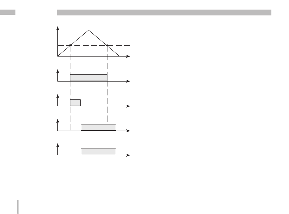
UMG 96RM-M
Limit value
Exceedance
Measured value
Lead time
Minimum
turn-on time
Comparator result
76
2 seconds
2 seconds
Page 77

UMG 96RM-M
Parameter list comparator and digital outputs
Address Format RD/WR Unit Note Adjustment Range Default
100 SHORT RD/WR - Address of the measured value,
Digital output 1 0..32000 0
101 SHORT RD/WR - Address of the measured value,
Digital output 2 0..32000 0
102 FLOAT RD/WR Wh Pulse value,
Digital output 1 -1000000..+1000000 0
104 FLOAT RD/WR Wh Pulse value,
Digital output 2 -1000000..+1000000 0
106 SHORT RD/WR 10ms Minimum pulse length (1=10 ms)
Digital output 1/2 1..1000 5 (=50ms)
107 SHORT RD/WR - Result from comparator group 1; 0,1 0
Link A, B, C
(1=and, 0=or)
108 FLOAT RD/WR - Comparator 1A, Limit value -1012-1..+1012-1 0
110 SHORT RD/WR - Comparator 1A,
Address of the measured value 0..32000 0
111 SHORT RD/WR s Comparator 1A,
Minimum turn-on time 0..32000 0
112 SHORT RD/WR s Comparator 1A, Lead time 0..32000 0
113 SHORT RD/WR - Comparator 1A, Operator 0,1 0
„>=“=0, „<“=1
114 FLOAT RD/WR - Comparator 1B, Limit value -1012-1..+1012-1 0
116 SHORT RD/WR - Comparator 1B,,
Address of the measured value 0..32000 0
117 SHORT RD/WR s Comparator 1B,
Minimum turn-on time 0..32000 0
118 SHORT RD/WR s Comparator 1B, Lead time 0..32000 0
119 SHORT RD/WR - Comparator 1B, Operator 0,1 0
„>=“=0 „<“=1
120 FLOAT RD/WR - Comparator 1C, Limit value -1012-1..+1012-1 0
77
Page 78

UMG 96RM-M
Address Format RD/WR Unit Note Adjustment Range Default
122 SHORT RD/WR - Comparator 1C,
Address of the measured value 0..32000 0
123 SHORT RD/WR s Comparator 1C,
Minimum turn-on time 0..32000 0
124 SHORT RD/WR s Comparator 1C, Lead time 0..32000 0
125 SHORT RD/WR - Comparator 1C, Operator 0,1 0
„>=“=0 „<“=1
126 SHORT RD/WR - Result from comparator group 2; 0,1 0
Link A, B, C
(1=and, 0=or)
127 FLOAT RD/WR - Comparator 2A, Limit value -1012-1..+1012-1 0
129 SHORT RD/WR - Comparator 2A,
Address of the measured value 0..32000 0
130 SHORT RD/WR s Comparator 2A,
Minimum turn-on time 0..32000 0
131 SHORT RD/WR s Comparator 2A, Lead time 0..32000 0
132 SHORT RD/WR - Comparator 2A, Operator 0,1 0
„>=“=0 „<“=1
133 FLOAT RD/WR - Comparator 2B, Limit value -1012-1..+1012-1 0
135 SHORT RD/WR - Comparator 2B,
Address of the measured value 0..32000 0
136 SHORT RD/WR s Comparator 2B,
Minimum turn-on time 0..32000 0
137 SHORT RD/WR s Comparator 2B, Lead time 0..32000 0
138 SHORT RD/WR - Comparator 2B, Operator 0,1 0
„>=“=0 „<“=1
139 FLOAT RD/WR - Comparator 2C, Limit value -1012-1..+1012-1 0
141 SHORT RD/WR - Comparator 2C,
Address of the measured value 0..32000 0
142 SHORT RD/WR s Comparator 2C,
Minimum turn-on time 0..32000 0
78
Page 79

Address Format RD/WR Unit Note Adjustment Range Default
143 SHORT RD/WR s Comparator 2C, Lead time 0..32000 0
144 SHORT RD/WR - Comparator 2C, Operator 0,1 0
„>=“ = 0 „<“ = 1
200 SHORT RD/WR - Select the source for
Digital output 1 0..4
201 SHORT RD/WR - Digital output 1 inverter 0..1
202 SHORT RD/WR - Select the source for
Digital output 2 0..4
203 SHORT RD/WR - Digital output 2 inverter 0..1
602 SHORT RD/WR - Value for output 1 0, 1
605 SHORT RD/WR - Value for output 2 0, 1
608 SHORT RD - State of output 1
609 SHORT RD - State of output 2
610 SHORT RD - Comparator result 1 Output A
611 SHORT RD - Comparator result 1 Output B
612 SHORT RD - Comparator result 1 Output C
613 SHORT RD - Comparator result 2 Output A
614 SHORT RD - Comparator result 2 Output B
615 SHORT RD - Comparator result 2 Output C
616 SHORT RD - Linkage result of comparator group 1
617 SHORT RD - Linkage result of comparator group 2
*1
0
*2
0
*1
0
*2
0
*1 0=comparator group, 1=pulse output, 2=reserved, 3=reserved, 4=reserved
*2 0= not inverted, 1=inverted
UMG 96RM-M
79
Page 80

UMG 96RM-M
Service and maintenance
The device is subject to various safety tests prior to
delivery and is marked with a seal. If a device is opened,
the safety tests must be repeated. A warranty is only
given for unopened devices.
Repair and calibration
Repairs and calibration can only be carried out
by the manufacturer.
Front membrane
The front membrane can be cleaned with a soft cloth
and common household cleaning agents. Acids and
acidic agents must not be used for cleaning.
Disposal
The UMG 96RM-M can be disposed of as electronic
scrap in accordance with the statutory recycling
provisions. The lithium battery must be disposed of
separately.
80
Service
If questions arise that are not described in this manual,
please contact the manufacturer directly.
We require the following information from you in order
to deal with questions:
- device designation (see nameplate),
- serial number (see nameplate),
- software release (see measured value display),
- measured voltage and supply voltage,
- precise description of the error.
Device calibration
The devices are calibrated by the manufacturer
at the factory - it is not necessary to recalibrate the device providing that the environmental conditions are
complied with.
Calibration intervals
It is recommended to have a new calibration carried out
by the manufacturer or an accredited laboratory every
5 years approximately.
Page 81

UMG 96RM-M
81
Page 82

UMG 96RM-M
Error messages
The UMG 96RM-M shows three different error messages
on the display:
- warnings,
- serious error and
- metering range exceedances.
If there are warnings and serious errors, the error
message is indicated by the symbol "EEE" followed by
an error number.
Symbol for an error
message
Error number
The three-digit error number is composed of the error
description and (if detectable by the UMG 96RM-M)
one or more error causes.
82
Symbol for an error
message
Error cause
Description of the error
Example of error message 911:
The error number is composed of serious error 910
and internal error cause 0x01.
In this example, an error occurred when reading the calibration from
the EEPROM. The device
must be sent to the manufacturer for inspection.
Page 83

UMG 96RM-M
Warnings
Warnings are less serious errors and can be
acknowledged with buttons 1 or 2. The measured values
continue to be recorded and displayed. This error is redisplayed after each voltage recovery.
Error Description of the error
EEE
500
Serious errors
The device must be sent to the manufacturer for
inspection.
Error Description of the error
EEE
910
The mains frequency cannot be
determined.
Possible causes:
The voltage on L1 is too small.
The mains frequency is not in the range
from 45 to 65Hz.
Error when reading the calibration.
Internal causes of the error
The UMG 96RM-M can usually determine the cause of
an internal error and then report it with the following error
code. The device must be sent to the manufacturer for
inspection.
Error Description of the error
0x01 EEPROM does not answer.
0x02 Address range exceeded.
0x04 Checksum error.
0x08 Error in the internal I2C bus.
83
Page 84

UMG 96RM-M
Metering range exceedance
Metering range exceedances are displayed for as long
as they are present and cannot be acknowledged.
A metering range is exceeded if at least one of the three
voltage or current measuring inputs is outside of its
specified metering range.
The phase in which the metering range exceedance
occurred is indicated with the "up" arrow. The "V"
and "A" symbols show whether the metering range
exceedance occurred in the current or voltage circuit.
A = current circuit
V = voltage circuit
Display of the phase (L1/L2/
L3) with the metering range
exceedance.
Limit values for metering range exceedance:
I = 7 Aeff
UL-N = 520 VL-N
84
Examples
A = current circuit
Fig.: Display of the metering range exceedance
in the current circuit of the 2nd phase (I2).
V = voltage circuit
Fig.: Display of the metering range exceedance
in the voltage circuit L3.
Page 85

Parameters of the metering range exceedance
A continuative error description is stored encoded
in the parameters of the metering range exceedance
(addr. 600) in the following format:
UMG 96RM-M
FFFFFFFF
Phase 1:
Phase 2:
Phase 3:
Example: Error in phase 2 in the current circuit:
0xF2FFFFFF
Example: Error in phase 3 in the voltage circuit UL-N:
0xFFF4FFFF
0x
1
1
2
2
4
4
Current:
U L-N
85
Page 86

UMG 96RM-M
Procedure in case of error
Possibility of error Cause Help
No display External fuse for the power supply has
No current display Measurement voltage not
The displayed current is too large or too
small.
The displayed voltage is too small or too
large.
The displayed voltage is too small. Metering range exceedance. Use voltage transformer.
tripped.
connected.
Measurement current not connected. Connect measurement current.
Current measurement in the wrong phase. Check and correct the connection if
Voltage transformer factor incorrectly
programmed.
The peak current value
at the measurement input was exceeded
by current harmonics.
The current at the measurement input was
exceeded.
Measurement in the wrong phase. Check and correct the connection if
Voltage transformer incorrectly
programmed.
The peak voltage value at the
measurement input was overwritten by
harmonics.
Replace fuse.
Connect measurement voltage.
necessary.
Read and program the current transformer
ratio on the current transformer.
Install current transformer with a higher
current transformer ratio.
Install current transformer with a lower
current transformer ratio.
necessary.
Read and program the voltage transformer
ratio on the voltage transformer.
Attention! It must be ensured that the
measurement inputs are not overloaded.
86
Page 87

Possibility of error Cause Help
Ind./cap. phase shift The current circuit is assigned to the
Real power is too small or too large. The programmed current transformer ratio
wrong voltage circuit.
is incorrect.
The current circuit is assigned to the
wrong voltage circuit.
The programmed voltage transformer ratio
is incorrect.
Check and correct the connection if
necessary.
Reading and programming the current
transformer ratio on the current
transformer
Check and correct the connection if
necessary.
Read and program the voltage transformer
ratio on the voltage transformer.
UMG 96RM-M
The active energy import/export is
inverted.
An output is not reacting.
"EEE" on the display See error messages.
No connection to the device. Incorrect device address Correct the device address.
Despite the aforementioned measures the
device does not work.
At least one current transformer
connection is inverted.
A current circuit is assigned to the wrong
voltage circuit.
The output was incorrectly programmed. Check the programming and correct if
The output was incorrectly connected. Check and correct the connection if
Different bus speeds (baud rate) Correct the speed (baud rate).
Device is defective. Send the device to the manufacturer
Check and correct the connection if
necessary.
Check and correct the connection if
necessary.
necessary.
necessary.
for inspection and include a detailed
description of the error.
87
Page 88

UMG 96RM-M
Technical data
General
Net weight (with attached connectors) 300g
Packaging weight (including accessories) 625g
Device dimensions ca. l = 42mm, w = 97mm, h = 100mm
Service life of the backlight 40,000 hours (50% of initial brightness)
Transport and storage
The following information applies for devices that are transported or stored in their original packaging.
Free fall 1m
Temperature K55 (-25 °C to +70 °C)
Relative humidity 0 to 90% RH
Ambient conditions during operation
The UMG 96RM-M is intended for use in weather-protected, fixed locations.
Protection class II according to IEC 60563 (VDE 0106, part 1).
Rated temperature range K55 (-10 °C .. +55 °C)
Relative humidity 0 to 75 % RH
Operational altitude 0 .. 2000 m above sea level
Degree of pollution 2
Installation position vertical
Ventilation Forced ventilation is not required.
Foreign body and water protection
- Front
- Back
- Front with seal
88
IP40 according to EN60529
IP20 according to EN60529
IP42 according to EN60529
Page 89

Supply voltage
Installation overvoltage category 300V CAT II
Protection of the power supply (fuse) 6 A, type C (approved by UL/IEC)
Nominal range 20V - 250V (45..65Hz) oder DC 20V - 300V
Working area +-10% from the nominal range
Power consumption max. 4.5VA / 2W
Connection capacity of the terminals (power supply)
Connectable conductor. Only one conductor may be connected per contact point!
Single-wire, multi-wire, finely stranded conductor 0.2 - 2.5mm2, AWG 26 - 12
Pin terminals, ferrules 0.2 - 2.5mm
Tightening torque 0.4 - 0.5Nm
Stripping length 7mm
Outputs
2 digital outputs, semi-conductor relay, not short circuit protected.
Switching voltage max. 33V AC, 60V DC
Switching current max. 50mAeff AC/DC
Reaction time 10/12 periods + 10ms *
Pulse output (energy pulses) max. 50Hz
* Reaction time at 50 Hz, for example: 200 ms + 10 ms = 210 ms
2
UMG 96RM-M
89
Page 90

UMG 96RM-M
Connection capacity of the terminals (outputs)
Rigid/flexible 0.14 - 1.5mm2, AWG 28-16
Flexible with ferrules without plastic sleeve 0.20 - 1.5mm
Flexible with ferrules with plastic sleeve 0.20 - 1.5mm
Tightening torque 0.20 - 0.25Nm
Stripping length 7mm
Voltage metering
Three-phase, 4-wire systems with nominal voltages up to 277V/480V (+-10%)
Three-phase, 3-wire systems, unearthed,
with nominal voltages up to
IT 480V (+-10%)
Overvoltage category 300V CAT III
Rated surge voltage 4kV
Metering range L-N 01) .. 300 Vrms
Metering range L-L 01) .. 520Vrms
(max. overvoltage 520 Vrms )
(max. overvoltage 900Vrms )
Resolution 0.01V
Crest factor 2.45 (relative to the metering range)
Impedance 4MOhm/phase
Power consumption approx. 0.1 VA
Sampling rate 21.33 kHz (50 Hz), 25.6 kHz (60 Hz) per measuring channel
Mains frequency
- Resolution
1)
The UMG 96RM can only determine measured values if a L-N voltage greater than 10 Veff or a L-L voltage larger than 18 Veff is applied
to at least one voltage measurement input.
45 Hz .. 65 Hz
0.01 Hz
2
2
90
Page 91

Current measurement
Rated current
Metering range
Crest factor
Resolution
Overvoltage category
Rated surge voltage
Power consumption
Overload for 1 sec.
Sampling rate
Connection capacity of the terminals (voltage and current measurement)
Connectable conductor. Only one conductor may be connected per contact point!
5A
0 .. 6Arms
1.98
0.1 mA (display 0.01 A)
300V CAT II
2kV
ca. 0.2 VA (Ri=5mOhm)
120 A (sinusoidal)
21.33 kHz (50 Hz), 25.6 kHz (60 Hz) per measuring channel
Current Voltage
Single-wire, multi-wire, finely stranded conductor
Pin terminals, ferrules
Tightening torque
Stripping length
0.2 - 2.5mm2, AWG 26-12 0.08 - 4.0mm2, AWG 28-12
0.2 - 2.5mm
0.4 - 0.5Nm 0.4 - 0.5Nm
7mm 7mm
UMG 96RM-M
2
0.2 - 2.5mm
2
91
Page 92

UMG 96RM-M
Serial interface
M-Bus 300, 600, 1200, 2400, 4800, 9600, 19200, 38400 baud
M-Bus device load max. 20 mA
Stripping length 7mm
Connection capacity of the terminals (M-Bus)
Single-wire, multi-wire, finely stranded conductor
Pin terminals, ferrules
Tightening torque
Stripping length
92
0.20 - 1.5mm
0.20 - 1.5mm
0.20 - 0.25Nm
7mm
2
2
Page 93

UMG 96RM-M
93
Page 94

UMG 96RM-M
Parameters of functions
Function Symbol Accuracy class Metering range Display range
Total real power P 0.55) (IEC61557-12) 0 .. 5.4 kW 0 W .. 999 GW *
Total reactive power QA, Qv 1 (IEC61557-12) 0 .. 5.4 kvar 0 varh .. 999 Gvar *
Total apparent power SA, Sv 0.55) (IEC61557-12) 0 .. 5.4 kVA 0 VA .. 999 GVA *
Total active energy Ea 0.55) (IEC61557-12) 0 .. 5.4 kWh 0 Wh .. 999 GWh *
Total reactive energy ErA, ErV 1 (IEC61557-12) 0 .. 5.4 kvarh 0 varh .. 999 Gvarh *
Total apparent energy EapA, EapV 0.55) (IEC61557-12) 0 .. 5.4 kVAh 0 VAh .. 999 GVAh *
Frequency f 0.05 (IEC61557-12) 45 .. 65 Hz 45.00 Hz .. 65.00 Hz
Phase current I 0.5 (IEC61557-12) 0 .. 6 Arms 0 A .. 999 kA
Measured neutral conductor current
Calculated neutral conductor current
Voltage U L-N 0.2 (IEC61557-12) 10 .. 300 Vrms 0 V .. 999 kV
Voltage U L-L 0.2 (IEC61557-12) 18 .. 520 Vrms 0 V .. 999 kV
Displacement factor PFA, PFV 0.5 (IEC61557-12) 0.00 .. 1.00 0.00 .. 1.00
Short-term flicker, long-term flicker Pst, Plt - - Voltage dips (L-N) Udip - - Voltage surges (L-N) Uswl - - Transient overvoltages Utr - - Voltage interruptions Uint - - Voltage unbalance (L-N)
Voltage unbalance (L-N)
1)
2)
Voltage harmonics Uh Class 1 (IEC61000-4-7) up to 2.5 kHz 0 V .. 999 kV
THD of the voltage
THD of the voltage
3)
4)
IN - - INc 1.0 (IEC61557-12) 0.03 .. 25 A 0.03 A .. 999 kA
Unba - - Unb - - -
THDu 1.0 (IEC61557-12) up to 2.5 kHz 0 % .. 999 %
THD-Ru - - -
94
Page 95

UMG 96RM-M
Function Symbol Accuracy class Metering range Display range
Current harmonics Ih Class 1 (IEC61000-4-7) up to 2.5 kHz 0 A .. 999 kA
THD of the current
THD of the current
Mains signal voltage MSV - - -
1) Referred to amplitude.
2) Referred to phase and amplitude.
3)
4)
THDi 1.0 (IEC61557-12) up to 2.5 kHz 0 % .. 999 %
THD-Ri - - -
* The display returns to 0 W when the maximum total energy values are reached.
3) Referred to mains frequency.
4) Referred to root mean square value.
5) Accuracy class 0.5 with ../5 A transformer.
Accuracy class 1 with ../1 A transformer.
95
Page 96

UMG 96RM-M
Parameter and Modbus address list
The following excerpt from the parameter list contains
settings that are necessary for proper operation of the
UMG 96RM, such as current transformers and device
addresses. The values in the parameter list can be
written and read.
In the excerpt, the measured value list files the measured
and calculated measured values, output status data
and recorded values so that they can be read.
Table 1 - Parameter list
Adress Format RD/WR Unit Note Adjustment Range Default
0 SHORT RD/WR - Device address 0..255
1 SHORT RD/WR kbps Baud rate (0=300, 1=600, 2=1200, 0..7 5
3= 2400, 4=4800, 5=9600. 6=19200,
7=38400 Baud
3 SHORT RD/WR Only for internal use
10 FLOAT RD/WR A Current transformer I1, primary 0..1000000
12 FLOAT RD/WR A Current transformer I1, sec. 1..5 5
14 FLOAT RD/WR V Voltage transformer V1, prim. 0..1000000
16 FLOAT RD/WR V Voltage transformer V1, sec. 100, 400 400
18 FLOAT RD/WR A Current transformer I2, primary 0..1000000
20 FLOAT RD/WR A Current transformer I2, sec. 1..5 5
22 FLOAT RD/WR V Voltage transformer V2, prim 0..1000000 400
(*1)
The values 0 and 248 to 255 are reserved and must not be used.
(*2)
The adjustable value 0 does not produce any sensible energy values and must not be used.
96
(*1)
1
(*2)
5
(*2)
400
(*2)
5
Page 97

UMG 96RM-M
Adress Format RD/WR Unit Note Adjustment Range Default
24 FLOAT RD/WR V Voltage transformer V2, sec. 100, 400 400
26 FLOAT RD/WR A Current transformer I3, primary 0..1000000 5
28 FLOAT RD/WR A Current transformer I3, sec. 1..5 5
30 FLOAT RD/WR V Voltage transformer V3, prim. 0..1000000 400
32 FLOAT RD/WR V Voltage transformer V3, sec. 100, 400 400
34 SHORT RD/WR Hz Frequency determination 0, 45 .. 65 0
0=Auto, 45 .. 65=Hz
35 SHORT RD/WR - Display contrast 0 .. 9 5
0 (low), 9 (high)
36 SHORT RD/WR - Backlight 0 .. 9 6
0 (low), 9 (high)
37 SHORT RD/WR - Display profile 0 .. 3 0
0=default display profile
1=default display profile
2=default display profile
3=only for internal use
38 SHORT RD/WR - Display change profile 0 .. 3 0
0..2=default display
change profiles
39 SHORT RD/WR s Changeover time 0 .. 60 0
40 SHORT RD/WR - Averaging time, I 0 .. 8* 6
41 SHORT RD/WR - Averaging time, P 0 .. 8* 6
42 SHORT RD/WR - Averaging time, U 0 .. 8* 6
45 USHORT RD/WR mA Response threshold of 0 .. 50 5
I1 .. I3
50 SHORT RD/WR - Password 0 .. 999 0 (no password)
* 0 = 5sec.; 1 = 10sec.; 2 = 15sec.; 3 = 30sec.; 4 = 1min.; 5 = 5min.; 6 = 8min.; 7 = 10min.; 8 = 15min.
97
Page 98

UMG 96RM-M
Adress Format RD/WR Unit Note Adjustment Range Default
81 SHORT RD/WR - Secondary address, 0..99
extended section 1
82 SHORT RD/WR - Secondary address, 0..99
extended section 2
83 SHORT RD/WR - Secondary address, 0..99
extended section 3
84 SHORT RD/WR - Secondary address, 0..99
extended section 4
500 SHORT RD/WR - Terminal assignment, I L1 -3..0..+3 +1
501 SHORT RD/WR - Terminal assignment, I L2 -3..0..+3 +2
502 SHORT RD/WR - Terminal assignment, I L3 -3..0..+3 +3
503 SHORT RD/WR - Terminal assignment, U L1 0..3 1
504 SHORT RD/WR - Terminal assignment, U L2 0..3 2
505 SHORT RD/WR - Terminal assignment, U L3 0..3 3
506 SHORT RD/WR - Clear min. and max. values 0..1 0
507 SHORT RD/WR - Clear energy meter 0..1 0
508 SHORT RD/WR - Force write EEPROM 0..1 0
Note: Energy values and minimum and maximum values are written to the EEPROM every 5 minutes.
509 SHORT RD/WR - Voltage connection diagram 0..7 0
510 SHORT RD/WR - Current connection diagram 0..8 0
511 SHORT RD/WR - Relative voltage for
THD and FFT 0, 1 0
The voltages for THD and FFT can be shown on the display as L-N or L-L values. 0=LN, 1=LL
600 UINT RD/WR - Metering range exceedance 0..0xFFFFFFFF
746 SHORT RD/WR s Period of time after which the
backlight will switch to standby 60 .. 9999 900
747 SHORT RD/WR s Brightness of the standby backlight 0 .. 9 0
98
Page 99

Only the first three positions (###) of a value are shown on the display. Values larger than
C
1,000 are marked with „k”. Example: 003k = 3000
Tabelle 2 - Adress list (frequently used measured values)
Addresse Format RD/WR Unit Note
750 SHORT RD - Software release
754 SERNR RD - Serial number
756 SERNR RD - Production number
800 FLOAT RD Hz Frequency
802 FLOAT RD - Voltage, positive sequence
804 FLOAT RD - Voltage, negative sequence
806 FLOAT RD - Voltage, zero sequence
808 FLOAT RD V Voltage L1-N
810 FLOAT RD V Voltage L2-N
812 FLOAT RD V Voltage L3-N
814 FLOAT RD V Voltage L1-L2
816 FLOAT RD V Voltage L2-L3
818 FLOAT RD V Voltage L1-L3
820 FLOAT RD - Fund. power factor, CosPhi; U L1-N IL1
822 FLOAT RD - Fund. power factor,, CosPhi; U L2-N IL2
824 FLOAT RD - Fund. power factor,, CosPhi; U L3-N IL3
826 FLOAT RD - Sum; CosPhi sum3=POsum3/Ssum3
828 FLOAT RD - Power factor; U L1-N IL1
830 FLOAT RD - Power factor; U L2-N IL2
832 FLOAT RD - Power factor; U L3-N IL3
834 FLOAT RD - Sum; Power factor sum3=Psum3/Ssum3
836 FLOAT RD % THD, U L1N, based on U0 L1
838 FLOAT RD % THD, U L2N, based on U0 L2
UMG 96RM-M
99
Page 100

UMG 96RM-M
Addresse Format RD/WR Unit Note
840 FLOAT RD % THD, U L3N, based on U0 L3
842 FLOAT RD % THD, U L1L2, based on U0 L1L2
844 FLOAT RD % THD, U L2L3, based on U0 L2L3
846 FLOAT RD % THD, U L1L3, based on U0 L1L3
848 FLOAT RD V Voltage, real part U1 L1N
850 FLOAT RD V Voltage, real part U2 L2N
852 FLOAT RD V Voltage, real part U3 L3N
854 FLOAT RD V Voltage, imaginary part U L1N
856 FLOAT RD V Voltage, imaginary part U L2N
858 FLOAT RD V Voltage, imaginary part U L3N
860 FLOAT RD A Current I1 L1
862 FLOAT RD A Current I2 L2
864 FLOAT RD A Current I3 L3
866 FLOAT RD A Vector sum; IN=I1+I2+I3
868 FLOAT RD W Real power P1 L1N
870 FLOAT RD W Real power P2 L2N
872 FLOAT RD W Real power P3 L3N
874 FLOAT RD W Sum; Psum3=P1+P2+P3
876 FLOAT RD var Fund. reactive power Q1 L1N
878 FLOAT RD var Fund. reactive power Q2 L2N
880 FLOAT RD var Fund. reactive power Q3 L3N
882 FLOAT RD var Sum; Qsum3=Q1+Q2+Q3
884 FLOAT RD VA Apparent power S1 L1N
886 FLOAT RD VA Apparent power S2 L2N
888 FLOAT RD VA Apparent power S3 L3N
890 FLOAT RD VA Sum; Ssum3=S1+S2+S3
892 FLOAT RD W Fund. real power P01 L1N
894 FLOAT RD W Fund. real power P02 L2N
896 FLOAT RD W Fund. real power P03 L3N
898 FLOAT RD W Sum; P0sum3=P01+P02+P03
900 FLOAT RD var Harmonic distortion power D1 L1N
902 FLOAT RD var Harmonic distortion power D2 L2N
100
 Loading...