

Page 1
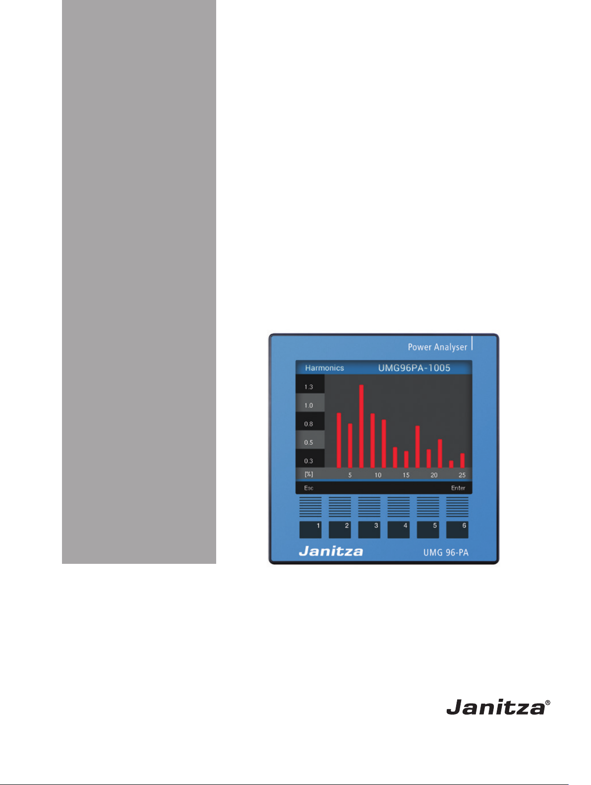
Power Quality Analyzer
UMG 96-PA
User Manual and Technical Data
Doc. no. 2.061.015.1b 07/2018
www.janitza.com
Janitza electronics GmbH
Vor dem Polstück 6
D-35633 Lahnau
Support phone number +49 6441 9642-22
Fax +49 6441 9642-30
E-mail: info@janitza.com
Internet: http://www.janitza.com
Page 2

UMG 96-PA www.janitza.de
Content
1. General 6
1. 1 Disclaimer 6
1. 2 Copyright notice 6
1. 3 Technical modifications 6
1. 4 Declaration of Conformity 6
1. 5 Comments on the Manual 6
2. Safety 8
2. 1 Safety Instructions 8
2. 2 Safety Measures 9
2. 3 Qualified Staff 9
3. Intended Use 10
3. 1 Input Check 10
3. 2 Intended Use 10
3. 3 Delivery Contents 11
3. 4 Deliverable accessories 11
4. Product Description 12
4. 1 Measurement Procedure 12
4. 2 Operating Design 12
4. 3 Network Analysis Software
GridVis® 12
4. 4 Performance characteristics 13
4. 5 Product Overview 14
5. Installation 16
5. 1 Installation site 16
5. 2 Installation position 16
5. 3 Securing the device 16
6. Network systems 17
6. 1 Voltage measurement 18
6. 2 Rated voltages 19
6. 2. 1 Three-phase 4-wire network with earthed neutral conductor 19
2
Page 3

www.janitza.de UMG 96-PA
7. Installation 20
7. 1 Connection to a PC 20
7. 2 Circuit breaker 21
7. 3 Supply voltage 21
7. 4 Measured voltage 22
7. 4. 1 Overvoltage 22
7. 4. 2 Frequency 22
7. 4. 3 Connection variants for voltage measurement 24
7. 5 Current measurement 24
7. 5. 1 Current measurement connection variants 25
7. 5. 2 Direction of the current 26
7. 5. 3 Total current measurement 26
7. 5. 4 Ammeter 26
8. Interface 27
8. 1 Screening 27
8. 2 Termination resistors 28
8. 3 Bus structure 29
9. Digital inputs and outputs 30
9. 1 Digital inputs 30
9. 1. 1 S0 pulse input 31
9. 2 Digital outputs 31
9. 3 LED status bar 32
10. Analog output 33
11. Operation 34
11. 1 Key assignment 34
11. 2 Measurement value display
"Overview" 34
11. 3 Option menu 34
11. 4 Overview of menu displays 35
3
Page 4

UMG 96-PA www.janitza.de
12. Configuration 36
12. 1 Language 36
12. 2 Communication 36
12. 3 Measurement 37
12. 3. 1 Rated current 37
12. 3. 2 Current and voltage transformers / Nominal current 39
12. 4 System 40
12. 4. 1 Firmware / Serial number 40
12. 4. 2 Time 40
12. 4. 3 Password 40
12. 4. 4 Reset 41
12. 5 Display 43
12. 6 Colors 44
12. 5. 1 Brightness 44
12. 5. 2 Standby 44
12. 5. 3 Brightness (standby) 44
13. Putting the device into service 45
13. 1 Supply voltage 45
13. 2 Measured voltage 45
13. 3 Frequency measurement 46
13. 4 Rotary field direction 46
13. 4. 1 Phasor diagram basics 47
13. 5 Measurement current 48
13. 6 Measurement range violation 49
13. 7 Checking the power measurement 49
13. 8 Checking communication 50
13. 9 Delete min./max. values
individually 50
13. 10 Harmonics 51
13. 11 Communication in the bus system 52
13. 11. 1 RS485
52
13. 12 Digital inputs/outputs 53
13. 12. 1 Digital
inputs 53
13. 12. 2 Digital
outputs 55
13. 13 Analog output 60
13. 14 “Drag indicator” function 61
13. 14. 1 Internal synchronization 61
13. 14. 2 External synchronization 62
13. 14. 3 Synchronization priority 64
13. 15 Recordings 65
13. 16 Tariff switching 66
4
Page 5

www.janitza.de UMG 96-PA
14. Overview of measurement value displays 68
15. Service and maintenance 74
15. 1 Repairs 74
15. 2 Front film 74
15. 3 Disposal 74
15. 4 Service 74
15. 5 Device calibration 74
15. 6 Re-calibration 74
15. 7 Firmware update 74
15. 8 Battery 75
15. 9 Procedure in the event of an error 76
16. Technical Data 77
16. 1 Function performance characteristics 80
16. 2 Modbus address list of frequently used measurement values: 82
16. 3 Number formats 83
16. 4 Dimension views 84
16. 5 Connection example 1 85
5
Page 6

UMG 96-PA www.janitza.de
1. General
1. 1 Disclaimer
Compliance with the information products
for the devices is a precondition for the safe
operation and for achieving the stated performance and product characteristics. Janitza
electronics GmbH does not accept any
liability for personal injury, material damage
or financial loss incurred as a result of not
complying with the information products.
Ensure that your information products are
kept easily accessible to read.
1. 2 Copyright notice
© 2017 - Janitza electronics GmbH - Lahnau.
All rights reserved.
Any duplication, editing, distribution or other
unauthorized utilization in whole or in part is
prohibited.
All trademarks and their corresponding rights
are the property of the respective owners of
those rights.
1. 3 Technical modifications
1. 5 Comments on the Manual
We welcome your comments. If anything in
this manual seems unclear to you, please let
us know by sending an e-mail to:
info@janitza.de
• Ensure that your device corresponds to the
installation guide.
• First, read and understand the documents
included with the product.
• Keep the product documents available
for the entire life cycle of the product and
provide them to any subsequent users.
• Learn about device revisions and the corresponding updates to the product documentation at www.janitza.de.
1. 4 Declaration of Conformity
The laws, norms and guidelines applied by
Janitza electronics GmbH in the production
of this product can be found in the declaration of conformity at www.janitza.de.
6
Page 7

www.janitza.de UMG 96-PA
7
Page 8
UMG 96-PA www.janitza.de
2. Safety
Please read this user manual as well as all
other publications that must be referred to
for working with this product. This applies
especially to installation, operation and maintenance.
Please follow all safety instructions and warnings. Not following the instructions may result
in personal injury or damage to the product.
Any unauthorized modifications to or use of
this device that exceeds its stated mechanical, electric or other operational limits may
result in personal injury or damage to the
product.
Any such unauthorized modification constitutes "misuse" and/or "negligence" in the
meaning of the warranty for this product,
and therefore invalidates the warranty for the
coverage of possible damages occurring as
a result.
The User Manual:
2. 1 Safety Instructions
Symbols used:
As an addition to the safety in-
c
C
Safety instructions are marked with a warning
triangle and depicted as follows depending
on the degree of hazard:
m
HAZARD!
structions, this symbol indicates
an electrical hazard.
Together with the word "Instructions," this symbol describes:
• Procedures that do not entail
any risk of injury.
• Important information, procedures or actions.
Indicates an immediate hazard
that results in serious or fatal
injury.
• Read before operating the device.
• Keep available for the entire life cycle of
the product and for reference.
Comply with the legal and safety guidelines
required additionally for the specific instance
of application when using the device.
m
WARNING!
m
CAUTION!
Indicates a possibly hazardous
situation that may result in serious or fatal injury.
Indicates a possibly hazardous
situation that may result in minor injury or material damage.
8
Page 9

www.janitza.de UMG 96-PA
2. 2 Safety Measures
When electrical devices are in operation,
certain parts of these devices are necessarily subject to dangerous levels of voltage.
Serious bodily harm or material damage
may therefore result if they are not handled
properly:
c
WARNING!
Serious bodily harm or death may result
from hazardous voltages.
For this reason, please note the following:
• Before making connections, ground
the device on the protective earth terminal, if available.
• Hazardous voltages can occur in any
of the circuits connected to the voltage supply.
• There may be hazardous voltages inside the device even after disconnecting the voltage supply.
• Outfit single-wire leads with ferrules.
• Only connect screw terminals with the
same number of poles that are of the
same make.
• Before starting to work, de-energize
the system.
Risk of injury from electric
voltage!
2. 3 Qualified Staff
This device is to be operated and maintained
only by qualified staff.
Qualified staff are people who are able to
recognize risks and avoid possible hazards
that the operation or maintenance of the
device may cause, based on their specialized
training and their experience.
c
WARNING!
If the device is not operated in accordance
with the documentation, safety is no longer
ensured and the device may pose a risk.
Risk of Injury from
Improper Use
9
Page 10
UMG 96-PA www.janitza.de
3. Intended Use
3. 1 Input Check
Proper transport and professional storage,
installation and assembly, as well as careful
control and maintenance, are all preconditions for the proper and safe operation of this
device.
Perform unpacking and packing with the usual care and without the use of force, and only
use suitable tools.
Perform a visual inspection of the devices to
ensure a proper mechanical condition.
Check the delivery contents for completeness before starting to install the device.
If it is to be assumed that safe operation
is no longer possible, the device is to be
placed out of order immediately and protected against unintended operation. It is to
be assumed that safe operation is no longer
possible if the device e.g.:
3. 2 Intended Use
The device is:
• intended to be built into control cabinets
and small distribution boards.
• not intended to be built into vehicles! The
use of the device in mobile equipment is
considered an exceptional environment
condition, and is only admissible with a
separate agreement.
• not intended to be built into environments
with hazardous oils, acids, gases, fumes,
dust, radiation, etc.
C
ATTENTION!
All of the screw terminals included in
the delivery contents are connected
to the device.
• shows visible signs of damage,
• no longer functions despite an intact power supply,
• has been exposed to longer periods of
adverse conditions (e.g. storage not consistent with the admissible climate limits
without an adjustment of the room climate,
thawing, etc.) or transport stresses (e.g.
fall from a great height even without any
outward visible signs of damage, etc.).
C
ATTENTION!
All of the delivered options and
design variants are described on the
delivery note.
10
Page 11

www.janitza.de UMG 96-PA
3. 3 Delivery Contents
Number Art. no. Name
1 52.32.xxx
1)
UMG 96-PA
1 33.03.360 Installation Guide
1 33.03.361 "GridVis Software" Quick Start Guide
1 10.01.896 Screw terminal, pluggable, 3-pole (auxiliary energy)
1 10.01.849 Screw terminal, pluggable, 4-pole (voltage measurement)
1 10.01.871 Screw terminal, pluggable, 6-pole (current measurement)
1 10.01.909 Screw terminal, pluggable, 3-pole (RS 485)
1 10.01.865
Screw terminal, pluggable, 10-pole
(digital inputs/outputs, analog output)
1 52.22.251 Mounting Kit
1)
See delivery note for item number
3. 4 Deliverable accessories
Item no. Name
21.01.058
Lithium battery CR2032, 3 V
(Authorization as per UL 1642)
29.01.065 Seal, 96 x 96
15.06.015 Interface converter RS485 <-> RS232
15.06.025 Interface converter RS485 <-> USB
11
Page 12

UMG 96-PA www.janitza.de
4. Product Description
The device is intended for:
• the measurement and calculation of electrical quantities such as voltage, current,
power, energy, harmonics in the building
installation, on distributors, circuit breakers
and busbar distributors.
• the measurement of measuring voltages and currents originating in the same
network.
• measurements in low-voltage networks
in which rating voltages of up to 600 V
conductor to ground and surges of overvoltage category III may occur.
• Measurement in medium and high-voltage
networks usually does not occur through
current or voltage transformers.
• being built into non-mobile control cabinets or small distribution boards. The
position at which it is built in is arbitrary.
• measurement in medium- and high-voltage
networks with current and voltage transformers.
• use in domestic and industrial settings.
• the measurement of current via external
../1 A or ../5 A current transformers.
• Directly on the device using the 6 keys
and the display.
• Via the programming software GridVis®.
• You can change and open data with the
help of the Modbus address list via the
Modbus protocol. You can find this list at
www.janitza.de.
This user manual only describes the 6-key
operation of the device. The network analysis
software GridVis® has its own "Online Help
Guide."
4. 3 Network Analysis Software GridVis®
You can program the device and read out the
data with the network analysis software GridVis® available at www.janitza.de. To do this,
a PC must be connected to the device e.g.
via a serial interface (RS485) or via a gateway
connection.
With the network analysis software GridVis®,
you can:
The measurement results can be displayed
and read out via the device interface for further processing.
4. 1 Measurement Procedure
The device:
• continuously measures and calculates all
effective values over a 200 ms interval.
• measures the real effective value (TRMS)
of the voltages and currents connected to
the measurement inputs.
4. 2 Operating Design
You can program the device in many ways
and/or recall measurement values.
• program the device.
• configure and read out recordings.
• analyze the data you read out.
• save data in the database.
• display measurement values graphically.
• program client-specific applications.
Malfunction can result
c
CAUTION!
If the device is connected improperly, it may
deliver measurement values with errors.
For this reason, please note the following:
• Measurement voltages and measurement currents must come from the
same network.
• Do not use the device to measure
direct current.
• Earth the conducting patch boards.
from an improper
connection
12
Page 13

www.janitza.de UMG 96-PA
4. 4 Performance characteristics
General
• Front board installation device measuring 96 x 96 mm
• Expansion by modules
• Connection via plug-in terminals with screw connections
• Color graphics display 320 x 240 px
• Control via 6 keys
• 3 voltage measurement inputs (600 V, CAT III)
• 3 current measurement inputs (via current transformer)
• 3 digital outputs
• 3 digital inputs
(configured as impulse counters with simultaneous power calculation
• 1 analog output (0 - 20 mA)
• Data storage 4 MByte Flash
• RS485 interface (Modbus RTU, Slave, up to 115 kbps)
• Recording of more than 2,000 measurement values
• Clock and battery
• Operating temperature range -10 °C .. +55 °C
Measurement uncertainty
• Active energy, measurement uncertainty class 0.5S for ../5A transformers
• Active energy, measurement uncertainty class 1 for ../1A transformers
• Reactive energy class 1
Measurement
• Recording of more than 800 measurement values
• Measurement in TN and TT networks
• Measurement in networks with rated voltages of up to L-L 720 Vrms and L-N 417 Vrms
(as per IEC)
• Measurement range for current 0.005 .. 6 Arms
• Real active value measurement (TRMS)
• continuous sampling of voltage and current measurement inputs
• Frequency range of the fundamental oscillation 45 Hz .. 65 Hz
• Measurement of the harmonics 1 to 25 for ULN and I
• ULN, ULL, I, P (drawn/delivered), Q (ind./cap.)
• 2 tariffs (switching via Modbus or digital input 1)
13
Page 14

UMG 96-PA www.janitza.de
4. 5 Product Overview
1
2
Fig. Front view of UMG 96-PA
3
4
5
8
7
6
1 Device Type
2 Description of the function keys
3 Key 1: Configuration menu, Back (ESC)
4 Key 2: Select digit, set option field ()
5 Key 3: Lower digit by 1, select menu item (), set option field ()
6 Key 4: Increase digit by 1, select menu item (), set option field ()
7 Key 5: Select digit, set option field ()
8 Key 6: Open option menu, activate entry, confirm selection (Enter)
14
Page 15
www.janitza.de UMG 96-PA
1
8
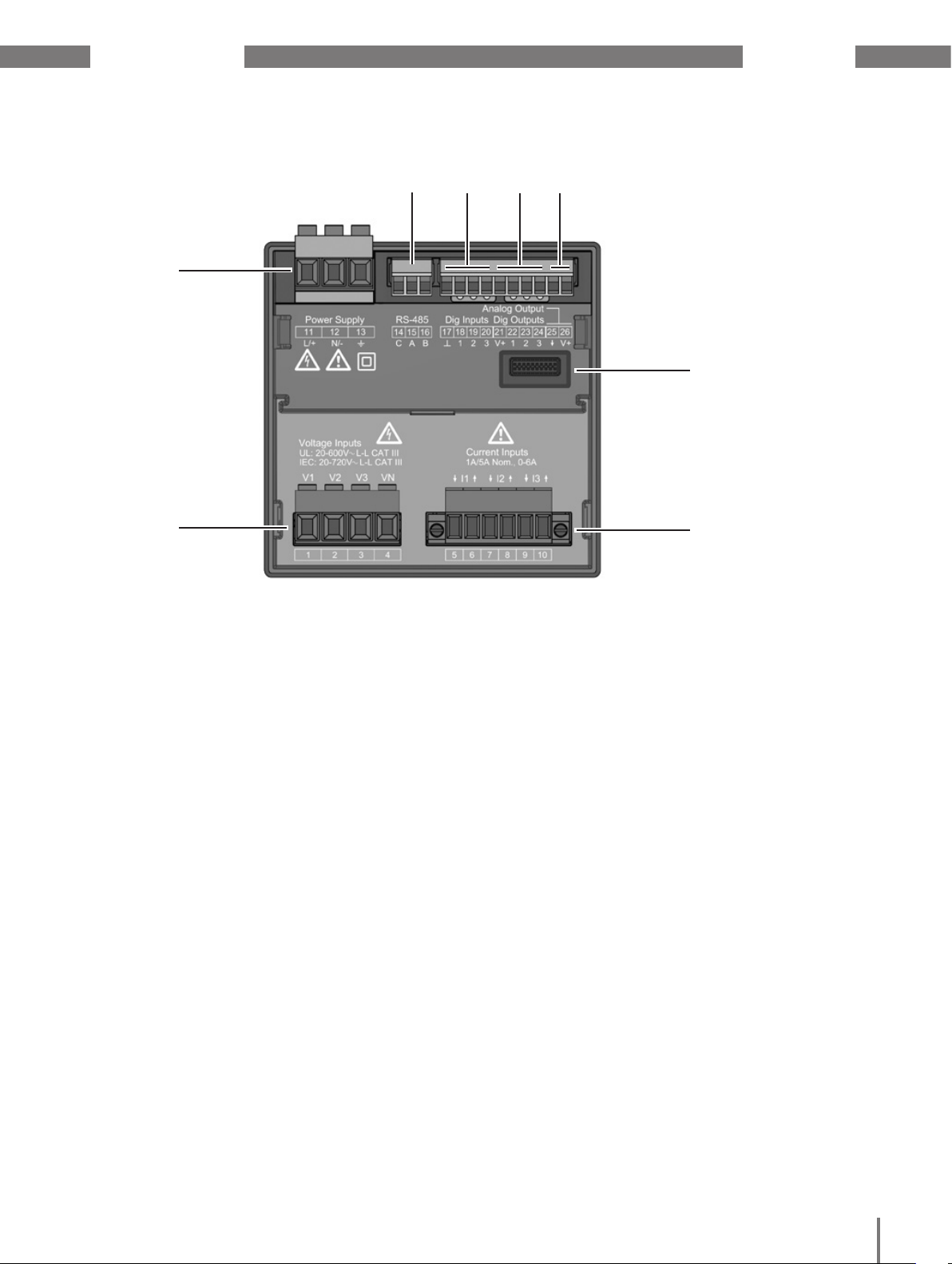
Fig. Back view of UMG 96-PA
2
3 4 5
6
7
1 Supply voltage
2 RS485 interface
3 Digital inputs
4 Digital outputs
5 Analog output
6 Module connector
7 Current measurement inputs I1 to I3
8 Voltage measurement inputs V1 to V3
15
Page 16
UMG 96-PA www.janitza.de
5. Installation
5. 1 Installation site
The device is suitable for installation in
non-mobile and weather-protected control
panels in indoor environments.
Plan on an earth for conducting control panels.
Material damage may
m
CAUTION!
result if the installation in-
structions are not followed!
Not following the installation instructions
may damage or destroy your device.
Comply with the details on the installation
position in sections „Installation“ and
„Technical Data“.
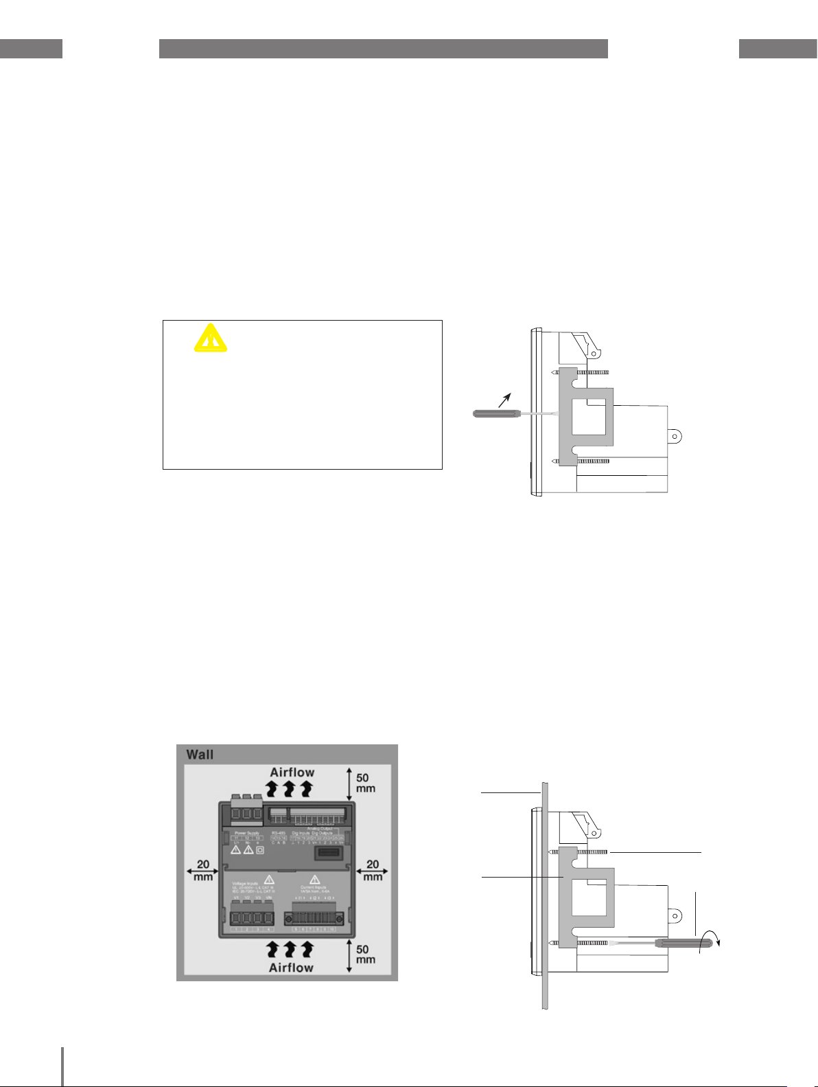
5. 2 Installation position
The cut-out dimensions of the control panel
are 92
+0,8
mm x 92
+0,8
mm.
To achieve sufficient ventilation, take the
following measures:
• Install the device vertically.
• Maintain a minimum clearance of 50 mm
above and below.
• Maintain a minimum clearance of 20 mm
on each side.
5. 3 Securing the device
The device is secured in the control panel
with the side mounting brackets. The brackets are to be removed e.g. using a screwdriver as a horizontal level before the device
is put in.
Fig. Side view of UMG 96-PA with mounting brackets.
The brackets can be loosened by leveraging them horizontally with a screwdriver.
Then slide in and snap the brackets into
place, and finally screw in the screws to secure the device.
• Turn the clamping screws until they just
touch the assembly plate.
• Then tighten the clamping screws with two
more rotations each (the mounting brackets may be destroyed if the screws are
tightened too much).
16
Fig. Back view of the installation posi-
tion of the UMG 96-PA
Assembly plate
Mounting
brackets
Clamping screw
Once the clamping screws
touch the surface of the
assembly plate: use two further
rotations at most to secure
the device
Screwdriver
Page 17

www.janitza.de UMG 96-PA
L1
E
L1
L2
L3
E
N
R
L1
L2
L3
EE
L1
L2
L3
EE
6. Network systems
Network systems and maximum rated voltages as per DIN EN 61010-1/A1:
Three-phase four-wire systems
with earthed neutral conductor
L2
N
L3
IEC U
UL U
L-N
L-N
/ U
417 VLN / 720 VLL
L-L:
/ U
347 VLN / 600 VLL
L-L:
EE
The device can be used in
• TN and TT networks
• domestic and industrial areas.
c
WARNING!
Risk of injury from
electric voltage!
If the device is exposed to measurement
voltage surges above the admissible overvoltage category, safety-related insulations
in the device may be damaged, whereupon
the safety of the product can no longer be
guaranteed.
Only use the device in environments in
which the admissible measurement surge
voltage is not exceeded.
17
Page 18

UMG 96-PA www.janitza.de
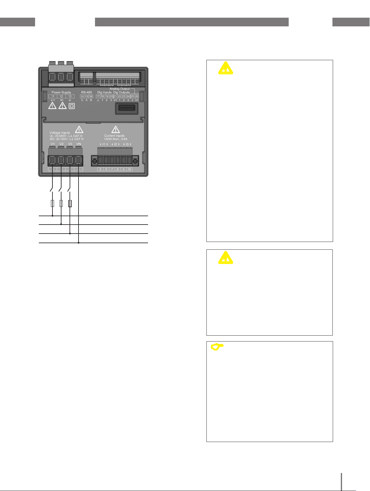
6. 1 Voltage measurement
You can use the UMG 96-PA to measure voltage in TN and TT systems.
Voltage measurement in the UMG 96-PA is
designed for the overvoltage category 600V
CATIII (measurement surge voltage 6 kV).
347V/600V 50/60Hz
L1
L2
L3
N
PE
L1
240V
50/60Hz
N
In systems without N, the measurement values that require an N are based on a calculated N.
c
WARNING!
Risk of injury from electric
voltage!
If voltage transformers are used, the connections on the secondary side may not be
short-circuited!
For this reason, please note the following:
• Check that the
voltage transformers have been properly installed. To do this, read the respective information about the voltage
transformers.
V1 V3V2 VN
AC/DC
4M
4M
4M
Voltage measurement
UMG 96-PA
Fig. Principle circuit diagram - Measurement in three-
phase 4-wire systems.
4M
Auxiliary energy
DC
18
Page 19

www.janitza.de UMG 96-PA
6. 2 Rated voltages
The following figures show lists of the networks and the corresponding network rated
voltages at which the device can be used.
6. 2. 1 Three-phase 4-wire network with earthed neutral conductor
U
/ U
L-N
L-L
66V / 115V
120V / 208V
127V / 220V
220V / 380V
230V / 400V
240V / 415V
260V / 440V
277V / 480V
347V / 600V
400V / 690V
417V / 720V
Maximum network voltage of the
network as per UL
Maximum network voltage of
the network
Fig. Network rated voltages as per EN 60664-1:2003
suited for measurement inputs
19
Page 20

UMG 96-PA www.janitza.de
7. Installation
7. 1 Connection to a PC
There are various options for connecting the
device to a PC:
1. Connection via an
interface converter:
PC with GridVis®
UMG 96-PA
RS232
RS232
RS485
RS485
PC with GridVis®
UMG 96-PA
USB
USB
RS485
RS485
2. Use of the UMG 96-PA (slave) via a UMG
(master) with gateway functionality (e.g.
UMG 512)
PC with GridVis®
Ethernet
Ethernet
20
UMG 512-PRO
as gateway
UMG 96-PA
Slave 1
ModbusModbus Modbus
UMG 96-PA
Slave 2
UMG 103
Slave 3
Page 21

www.janitza.de UMG 96-PA
7. 2 Circuit breaker
For building installation, plan for a suitable
circuit breaker for the supply voltage to
de-energise the device.
• The circuit breaker must be installed near
the device and easily accessible to the
user.
• The switch must be marked as the circuit
breaker for this device.
7. 3 Supply voltage
The device needs a supply voltage to operate. The type and amount of supply voltage
required for your device can be found on the
ratings plate.
The supply voltage is connected on the rear
of the device via terminal blocks.
Before connecting the supply voltage, ensure
that the voltage and frequency correspond to
the details on the ratings plate.
Connect the supply voltage through a UL/IEC
approved fuse.
After the supply voltage has been connected, an indicator will appear on the display. If
no indicator appears, check that the supply
voltage is within the rated voltage range.
m
CAUTION!
result from failure to com-
ply with the connection
requirements.
Noncompliance with the connection requirements may result in your device being
damaged or destroyed.
For this reason, please note the following:
• Comply with the details on voltage and
frequency on the ratings plate.
• Connect the supply voltage through a
fuse in accordance with the technical
specifications.
• Do not source the supply voltage on
the voltage transformers.
• Plan for a fuse for the neutral conductor if the neutral conductor connection
to the source is not earthed.
L
N
PE/FE
1.)
Material damage may
1.)
2.)
Fuse
(UL/IEC listed)
2.)
Disconnector
(Circuit breaker)
Functional earth
c
WARNING!
Risk of injury from electric
voltage!
Serious bodily harm or death may result
from:
• Touching bare or stripped wires that are
live.
• Inputs on the device that are dangerous
to touch.
For this reason, please note the
following:
• The inputs for supply voltage are
dangerous to touch.
• De-energise your system before
starting work!
Fig. Connection example for supply voltage
ATTENTION!
C
If the functional earth is not
connected, the device displays a
non-applied residual voltage.
21
Page 22

UMG 96-PA www.janitza.de
Overcurrent protective device for the
line protection of the supply voltage
Recommendation for the overcurrent protective device for the line protection of the
supply voltage, depending on the variants:
• Option 230 V:
6 - 16 A (Char. B)
• Option 24 V:
1 - 6 A (Char. B)
C
Recommendation for the maximum number
of devices on one miniature circuit breaker,
depending on the variants:
• Option 230 V:
• Option 24 V:
ATTENTION!
The circuit breaker serves only as
line protection - it does not provide
protection for the device!
For one miniature circuit breaker B6A,
maximum of 4 devices.
For one miniature circuit breaker B16A,
maximum of 11 devices.
For one miniature circuit breaker B6A,
maximum of 3 devices.
For one miniature circuit breaker B16A,
maximum of 9 devices.
7. 4 Measured voltage
The device has 3 voltage measurement inputs (V1 to V3) on the back of the device.
7. 4. 1 Overvoltage
The voltage measurement inputs are suitable for measurement in networks in which
overvoltage of category 600 V CAT III (voltage
measurement surge of 6 kV) may occur.
7. 4. 2 Frequency
The device:
• requires the network frequency to measure
and calculate the measurement values.
• is suitable for measurement in networks
in which the fundamental oscillation of the
voltage is within the range of 45 to 65 Hz.
The network frequency is derived from the
measured voltage in phase L1. The sampling
rate of the voltage and current measurement
inputs is derived from the network frequency.
If the measurements have severely distorted voltages, it will no longer be possible to
precisely determine the frequency of the
fundamental oscillation of the voltage. I.e. the
corresponding network frequency should be
stipulated for measured voltages that exhibit
severe distortions.
(Voltage distortions occur e.g. in measurements of consumers operated with a phase
angle control). Current distortions do not
affect the determination of the frequency.
22
More information can be found in Section 12
Configuration / Rated frequency"
Page 23
www.janitza.de UMG 96-PA
1.)
Fuse
1) 1) 1)
2) 2) 2)
Fig. Connection example for voltage measurement.
(UL/IEC listed)
2.)
Disconnector
(Circuit breaker)
L1
L2
L3
N
c
WARNING!
Risk of injury from electric
voltage!
Serious bodily harm or death may result
from not complying with the connection
requirements for the voltage measurement
inputs.
For this reason, please note the following:
• De-energise your system before
starting work! Check that it has been
de-energised!
• Connect voltages that are over the
admissible network rated voltages
through voltage transformers.
• The voltage measurement inputs on
the device are dangerous to touch!
• Install a circuit breaker as described in
Section „7. 2 Trennschalter“.
• Use a UL/IEC approved overvoltage
protective device with a rating value
that is measured for short-circuit current at the point of connection.
c
CAUTION!
Malfunction can result from
an improper connection
If the device is connected improperly, it may
deliver measurement values with errors.
For this reason, please note the following:
• Measurement voltages and currents
must come from the same network.
• The device is not suitable for measuring direct current.
ATTENTION!
C
The device can only determine measurement values if there is a voltage
L1-N greater than 20 Veff (4-wire
measurement) or a voltage L1-L2
greater than 34 Veff (3-wire measurement) at the voltage measurement
input V1.
As an overvoltage
protective device for the voltage
measurement, use a line protection
(1 - 10 A) with IEC/UL approval.
23
Page 24
UMG 96-PA www.janitza.de
7. 4. 3 Connection variants for voltage measurement
V1
V2
Fig. Voltage measurement in the three-phase
four-wire system
V1
V2
V3
V3
VN
VN
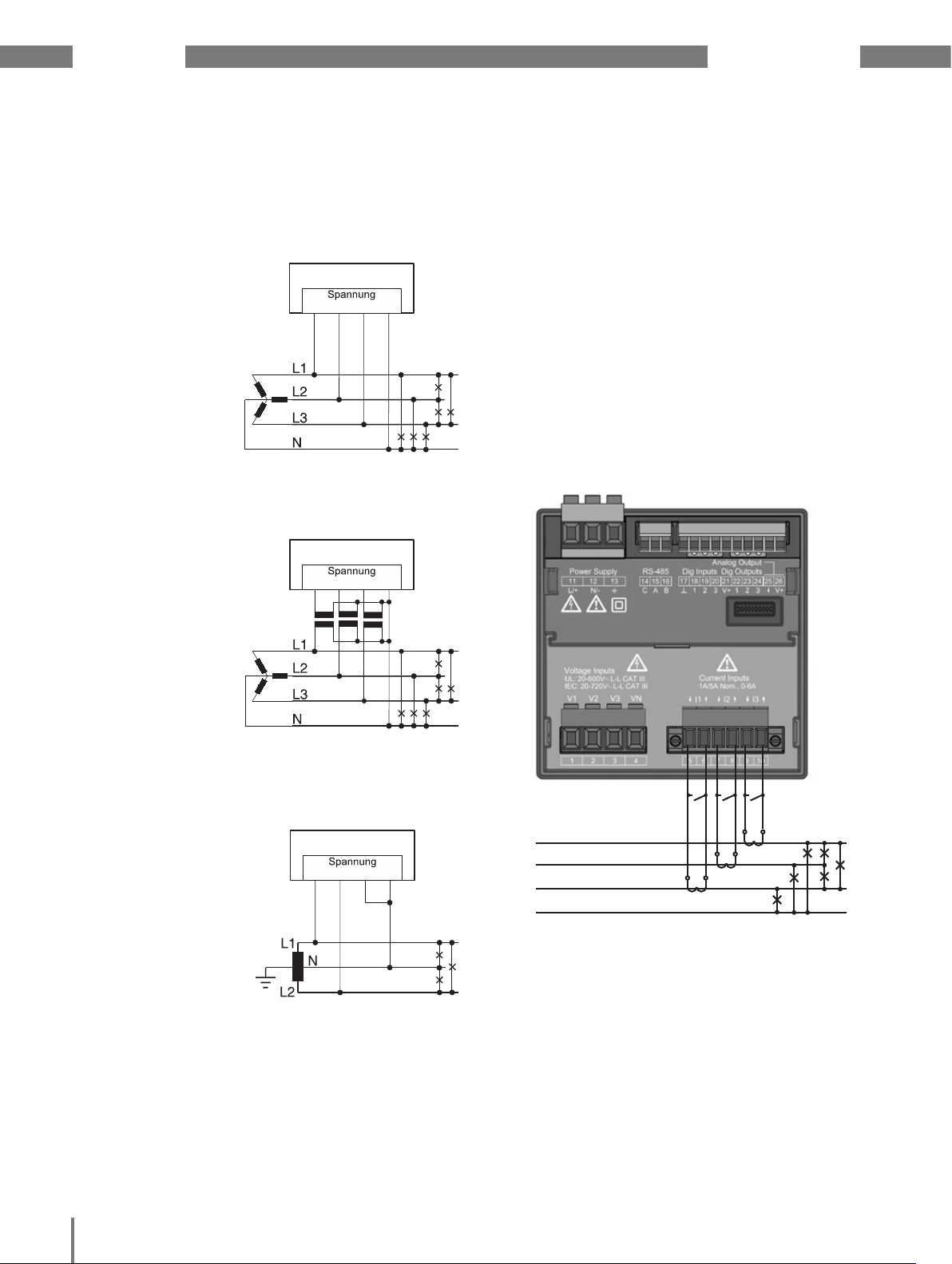
7. 5 Current measurement
The device:
• is designed to be connected to current
transformers with secondary currents of
../1 A and ../5 A.
• is only approved for measuring current
through current transformers.
• does not measure direct currents.
The factory preset current transformer ratio
is 5/5 A, and may need to be adjusted to the
current transformer in use.
Fig. Voltage measurement in the three-phase
four-wire system
V1
V2
Fig. Voltage measurement in the single-phase
three-wire system
V3
VN
L1
L2
L3
N
Fig. Connection example "Current measurement through
a current transformer."
S1 S2
S1 S2
S1 S2
24
Page 25
www.janitza.de UMG 96-PA
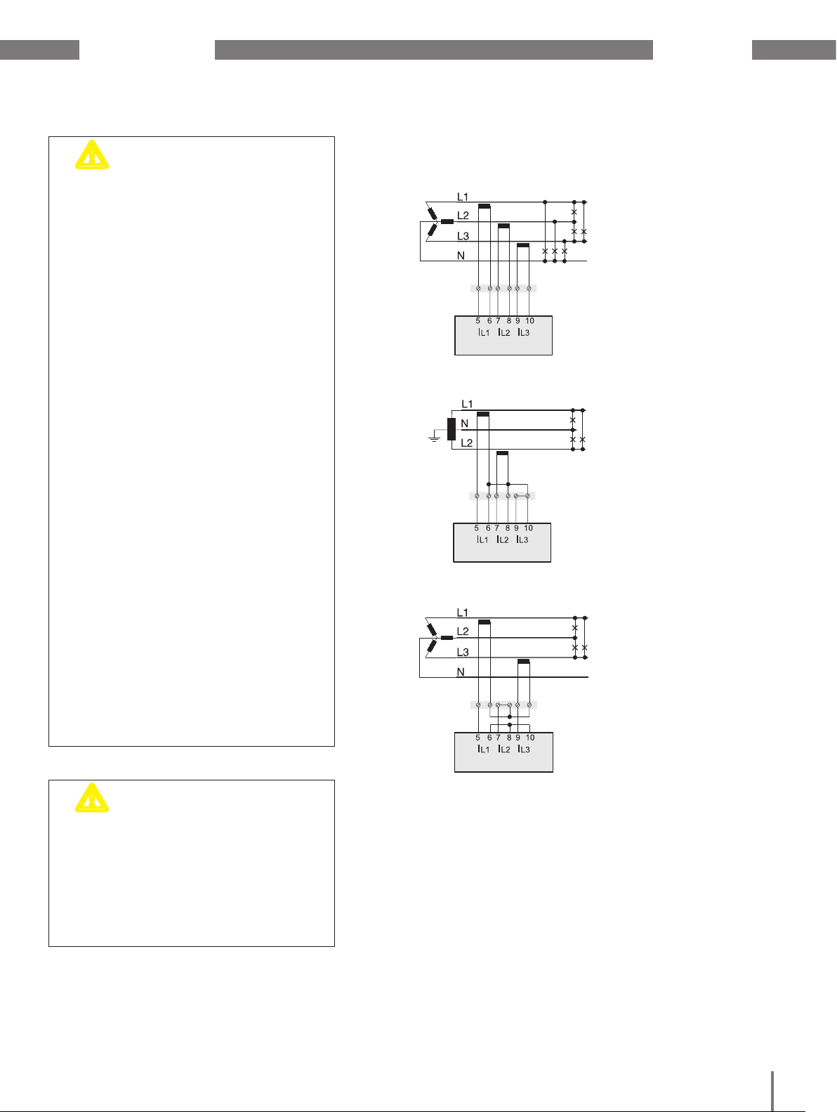
7. 5. 1 Current measurement connection
m
WARNING!
tric voltage on the current
transformers!
Voltage peaks that are extremely dangerous
to touch may occur on current transformers
operated with an open secondary side
that may result in serious bodily harm or
death.
For this reason, please note the following:
• De-energise your system before starting work! Check that it has been de-energised!
• Avoid open operation of the current
transformers.
• Short-circuit uncharged current transformers.
• The secondary terminals of the current
transformer must be short-circuited
before the power supply lines are disconnected.
• If a test switch that automatically
short-circuits the current transformer
secondary leads is available, it is sufficient to put this into the "test" position
provided the short-circuiters have been
checked beforehand.
• Only use current transformers
that have a base insulation as per
IEC 61010-1:2010.
• Ensure that the attached screw terminal is sufficiently secured to the device
with the two screws.
• Even "open-safe" current transformers are dangerous to touch if they are
operated openly.
Risk of injury from elec-
variants
Fig.
Current measurement
via current transformer in three-phase
four-conductor
system
Fig.
Current measurement in
single-phase three-conductor system
Fig.
Current measurement via
2 current transformers in
three-phase four-conductor
system
m
WARNING!
Risk of injury from electric
voltage!
At high measurement currents, temperatures
of up to 80 °C can develop at the terminals.
Therefore, use leads that are designed to
have an operating temperature of at least
80 °C.
25
Page 26

UMG 96-PA www.janitza.de
7. 5. 2 Direction of the current
The current direction can be individually corrected on the device or via the serial interfaces for each phase.
In the case of incorrect connection, the current transformer does not need to be subsequently reconnected.
7. 5. 3 Total current measurement
If the current measurement takes place via
two current transformers, the total transformer ratio of the current transformer must be
programmed on the device. Setting the current transformer ratios is described in Section
„Messwandler“.
Example:
The current measurement is performed via
two current transformers. Both current transformers have a transformer ratio of 1000/5 A.
The total measurement is then carried out
with a total current transformer 5+5/5 A .
7. 5. 4 Ammeter
If you want to measure the current not only
with the UMG but also with the ammeter,
the ammeter must be connected in series to
the UMG.
UMG
I
S2
1
S
A
Einspeisung
Supply
(k)S
1 S2(l)
2(L)(K)P1
P
Fig. Circuit diagram with additional ammeter connected
in series
Verbraucher
Consumer
The device must then be set as follows:
Primary current:
1000 A + 1000 A = 2000 A
Secondary current: 5 A
UMG
I
S
S2
1
Einspeisung 1
Supply 1
1P1
1S1
(K)
(k)
(l)
(L)
1S
1P2
Verbraucher A
Consumer A
2
P1
1S1 1S2 2S1 2S2
Fig. Example of voltage measurement via a total current
transformer
P2
Einspeisung 2
Supply 2
2S1
(k)
(l)
2S2
Verbraucher B
Consumer B
2P
(K)
(L)
2P2
1
26
Page 27

www.janitza.de UMG 96-PA
8. Interface
The RS485 interface in this device is a 3-pole
plug contact that communicates via the Modbus RTU protocol.
Cable types:
• Recommendation: Unitronic Li2YCY(TP)
2x2x0.22 (Lapp cable)
Connection options for the connectors:
• 0.2 - 1.5 mm
(see Section "Technical Data")
e.g.
Connection
to the
UMG 604
as gateway
(master)
A
B
Data GND
2
RS485 bus
A
B
A
B
e.g.
Connection
of further
slave devices
C
CAT cables are not suitable for bus
wiring. Use the cable types recommended for this purpose.
8. 1 Screening
Use a drilled and shielded cable for the connections via the interface, and observe the
following points for the shielding:
• Earth the screens of all cables that lead to
the cabinet where they enter the cabinet.
• Connect the screen over a larger area and
in a manner that will conduct well, to a
low-noise earth.
• Do NOT connect the screen to terminal C
(GND)
• Gather the cables mechanically above the
earthing clamp in order to avoid damage
due to cable movement.
• Use suitable cable glands to feed the cables into the cabinet - for example armored
conduit couplings.
ATTENTION!
Fig. RS485 interface, 3-pole plug contact
RS485 bus
A
B
Data GND
Fig. RS485 interface, 3-pole plug contact with termina-
tion resistor (item no. 52.00.008)
120 Ω
A
B
Cable
Strain relief
Screen braid
of the cable
Earthing clamp
Low-noise earth
Fig. Screening procedure at cabinet entry.
27
Page 28

UMG 96-PA www.janitza.de
m
CAUTION!
Atmospheric discharge may cause transmission errors and hazardous voltages on the
device.
For this reason, please note the following:
• Place the screening on the functional
earth (PE) at least once.
• For larger sources of interference, put
the frequency inverter in the control
cabinet and position the screening as
close as possible on the device to the
functional earth (PE).
• Maintain a maximum cable length of
12000 m at a baud rate of 38.4 k.
• Use screened cables.
• Position interface leads so they are
spatially separated or additionally insulated from the components carrying
network voltage.
Transmission errors and
risk of injury result from
electrical interference.
8. 2 Termination resistors
The cable is terminated with resistors (120
Ohm, 1/4 W) at the beginning and at the end
of a segment.
The device does not contain any termination
resistors.
Correct
Incorrect
Terminal strip in the cabinet.
Device with RS485 interface.
(without termination resistor)
28
Device with RS485 interface.
(with termination resistor on the
device)
Page 29

www.janitza.de UMG 96-PA
8. 3 Bus structure
• All devices are connected in a bus structure (line).
• Each device has its own address within the
bus (see also Parameter programming).
• Up to 32 subscribers can be connected
together in a single segment.
• The cable is terminated with resistors (bus
termination 120 Ohm, 1/4 W) at the beginning and at the end of a segment.
• With more that 32 subscribers, repeaters
(amplifiers) must be used to connect the
individual segments.
• Devices for which the bus connection is
switched on must be under current.
Master
Power supply necessary
Bus terminator on
T
T
Slave
• It is recommended that the master be
placed at the end of a segment.
• If the master is replaced with a bus connection, the bus must be switched off.
• Replacing a slave with a bus connection
that is either switched on or de-energised
can destabilise the bus.
• Devices that are not connected to the bus
can be replaced without destabilising the
bus.
T
Slave Slave Repeater
T
Slave
Fig. Bus structure
Slave
T
Slave Slave
29
Page 30

UMG 96-PA www.janitza.de
9. Digital inputs and outputs
The device has
• 3 digital inputs and
• 3 digital outputs.
External
17
18
Digital
Input 1
19
Digital
Input 2
auxiliary voltage
-
S1
S2
9. 1 Digital inputs
The UMG96-PA has three digital inputs to
each of which you can connect one signal
transducer. When a signal is present, the
corresponding LED lights up green.
An input signal is detected on a digital input if
• a voltage of at least 18 V and maximum 28
V DC (typically at 4 mA) is applied.
• a current of at least 1 mA and maximum 6
mA flows.
UMG 96-PA
Digital inputs 1-3
LED
LEDLED
2k21
2k21
2k21
2k21
24V DC
+
C
Note the correct polarity of the supply voltage.
ATTENTION!
+
-
Fig. Connection of digital inputs
Transmission errors
c
CAUTION!
and material damage
result from electrical
interference.
2k21
2k21
Fig. Example for the connection of external switch
contacts S1-S3 to digital inputs 1, 2 and 3.
20
Digital
Input 3
S3
30
For wiring over 30 m, there is an increased
probability of transmission errors and
damage to the device from atmospheric
discharge.
Use screened wiring for connections to
the digital inputs and outputs.
Page 31

www.janitza.de UMG 96-PA
9. 1. 1 S0 pulse input
You can connect an S0 pulse transducer per
DIN EN62053-31 to any digital input.
This requires an auxiliary voltage with an
output voltage in the range 18 .. 28V DC and
a resistor of 1.5 kOhm.
9. 2 Digital outputs
External
auxiliary voltage
-
UMG 96-PA
Digital inputs 1-3
LED
LEDLED
Fig. Example for the connection of an S0 pulse transducer to digital input 1.
2k21
2k21
2k21
2k21
2k21
2k21
17
18
Digital
Input 1
19
Digital
Input 2
20
Digital
Input 3
1.5k
S0 pulse
transducer
24V DC
+
The device has three digital outputs which:
• are galvanically separated from the analysis electronics using optocouplers.
• have a joint reference.
• are not short-circuit proof.
• require an external auxiliary voltage.
• can be used as impulse outputs.
• can switch between AC and DC loads.
• can be controlled via Modbus.
• can display the results of comparators.
c
CAUTION!
Material damage from
connection errors
The digital outputs are not short-circuit
proof! Connection errors may therefor result
in damage to the connections.
Pay attention to the correct wiring when
connecting to the outputs.
C
Functions for the digital outputs can
be adjusted clearly in the GridVis®
software (see www.janitza.de).
Use of the GridVis® software
requires a connection between the
device and the PC via an interface.
ATTENTION!
m
CAUTION!
Measurement errors in use
as pulse output
When using the digital outputs as a pulse
output, measurement errors may result from
residual ripple.
So use a power adapter whose residual
ripple is less than 5% for the supply voltage (DC) to the digital inputs and outputs.
31
Page 32

UMG 96-PA www.janitza.de
~
Fig. Connection of digital/pulse outputs
UMG 96-PA
21
LED
Digital Ouput 1
22
External
auxiliary voltage
24V DC
+
DC
K1
9. 3 LED status bar
The different statuses of the inputs and outputs are displayed via the LED status bar on
the back of the device.
Digital inputs
The LED assigned to a respective input lights
up green when a signal of at least 1 mA flows
on this interface.
Digital outputs
The LED assigned to a respective output
lights up red when the output is set as
enabled - regardless of whether there is a
continuing connection to this interface.
-
LED status bar
Digital inputs
LED status bar
Digital outputs
LEDLED
Digital Ouput 2
Digital Ouput 3
23
24
Fig. Example for the connection of two
relays to the digital outputs
DC
K2
32
Page 33

www.janitza.de UMG 96-PA
10. Analog output
The device has 1 passive analog output,
which can emit current of 0 - 20 mA. An
external power adapter (24 V DC) is required
for operation.
The connected load impedance may not
exceed a resistance of 300 Ohm.
If the analog output is connected to greater resistance, the output range (20 mA) is
limited.
The measurement value, initial and final values, and the output range 4 - 20 mA or 0 - 20
mA assigned to the analog output can be set
using the GridVis® software (cf. Section 13
"Analog Output")
-
=
+
External
operating voltage
UMG 96-PA
Analog output 1
230 V AC
26
25
+
+
24 V DC
-
Analog inputs
Fig. Analog output connection
33
Page 34

UMG 96-PA www.janitza.de
11. Operation
The device is operated using six function
keys that are assigned to different functions,
depending on the context:
• Selection of measurement value displays.
• Navigation in the menu.
• Control of device settings.
Display title
Measurement
values
Labeling
of the function
keys
Function
Keys
Fig. UMG 96-PA
Measurement value display "Overview"
11. 2 Measurement value display "Overview"
After returning to the network, the device
starts with the measurement value display
"Overview."
This measurement value display includes the
device name and an overview of the important measurement values. In its delivery state,
the device name consists of the device type
and the serial number of the device.
Press key 1 (Esc) repeatedly to open the
measurement value display "Overview."
11. 1 Key assignment
Key
Function
• Option menu
• Leave menu, Back (Esc)
• Press multiple times:
Back to the measurement value display "Overview"
• Select digit
• Set option field ()
• Change (Digit -1)
• Set option field ()
• Select menu item ()
• Change (Digit +1)
• Set option field ()
• Select menu item ()
• Select digit
• Set option field ()
Fig. Measurement value display
"Overview"
11. 3 Option menu
If you are in the measurement value display
"Overview," open the main menu with key 1
(Esc).
Fig. UMG 96-PA Main menu
34
• Open option menu
• Activate entry
• Confirm selection (Enter)
Key 1 (Esc): Main menu
Page 35

www.janitza.de UMG 96-PA
11. 4 Overview of menu displays
Main menu
Summary (start screen)
Voltage
Voltage L-N
Voltage L-L
Linewriter
Current
Current
THD-I
Linewriter
Power
Sum power
Active power
Reactive power
Apparent power
Linewriter active power
Linewriter reactive power
Linewriter apparent power
Energy
Active energy
Reactive energy
Apparent energy
Tariff
Consumption overview
Active energy/month
Reactive energy/month
Apparent energy/month
Active energy/day
Reactive energy/day
Apparent energy/day
Harmonics
Voltage L1
Voltage L2
Voltage L3
Current L1
Current L2
Current L3
Oscilloscope
Voltage L1
Voltage L2
Voltage L3
Voltage L1-3
Current L1
Current L2
Current L3
Current L1-3
Phasor diagram
System
Configuration
Language
Communication
Field bus: Device address
Field bus: Baud rate
Field bus: Framing
Measurement
Measurement
Current transformer
Voltage transformer
Nominal current
Nominal frequency
System
Version
Serial no.
Time
Password
Reset
Display
Colors
Overview COM ports
Comparator 1
Comparator 2
Select menu:
• Select the menu item with the keys 3 () and
4 ().
• Confirm this by pressing key 6 (Enter).
• You can exit the selection by pressing key 1
(Esc).
35
Page 36

UMG 96-PA www.janitza.de
12. Configuration
The device must be connected to a power
supply to configure it. To do so, proceed as
described in „13. 1 Supply voltage“.
• If you are not in the measurement value
display "Overview," switch to this view by
repeatedly pressing key 1 (Esc).
• Open the main menu with key 1 (Esc).
With keys 3 () and 4 (), select "Sys-
tem" and confirm your selection with key 6
(Enter).
• Select "Configuration" and confirm by
pressing key 6 (Enter).
Fig. Main menu,
Selection "System"
• With keys 3 () and 4 (), select the language you want ("German," "English").
• Confirm your selection by pressing key 6
(Enter).
• Exit the configuration with key 1 (Esc).
• Open the main menu with key 1 (Esc).
• Select the measurement value display you
want with keys 3 () and 4 (). Confirm
your selection by pressing key 6 (Enter) or
jump directly to the measurement value
display "Overview" by pressing key 1 (Esc).
12. 2 Communication
Set the parameters for the RS485 interface of
your device in the configuration menu.
12. 1 Language
In the configuration menu, you can set the
language for the measurement value displays
and menus in "Language."
• Open the configuration menu (see Section
12 "Configuration").
• With keys 3 () and 4 (), select the item
"Language."
• Confirm by pressing key 6 (Enter).
Fig. Configuration menu,
Selection "Language"
Fig. Configuration menu,
Selection "Communication"
• Open the configuration menu (see Section
12 "Configuration").
• With keys 3 () and 4 (), select the menu
item "Communication."
• Confirm by pressing key 6 (Enter).
• With keys 3 () and 4 (), select the parameter you want
- Device address,
- Baud rate
- Data framework.
• Confirm your selection by pressing key 6
(Enter).
• Change the parameter sizes with keys 3
() and 4 ().
Device address: Set the digit position with
keys 2 () and 5 ().
• Confirm by pressing key 6 (Enter).
• Exit the menu "Communication" with key
1 (Esc).
36
Page 37

www.janitza.de UMG 96-PA
• Exit the configuration menu with key 1
(Esc).
• Open the main menu with key 1 (Esc).
• Select the measurement value display you
want with keys 3 () and 4 (). Confirm
your selection by pressing key 6 (Enter) or
jump directly to the measurement value
display "Overview" by pressing key 1 (Esc).
Fig. Menu Communication,
Selection "Device address"
Settings:
• Device address:
Select a device address for the device that
the device will be addressed with in the
bus. This address must be unique within
the bus structure.
Settings range: 1 - 250
Default: 1
• Baud rate:
Select a uniform baud rate for all of the
devices within the bus structure.
Settings range: Auto, 9600, 19200,
38400, 57600, 115200 kbps
Default: Auto
• Data framework:
Select a uniform data framework for all of
the devices within the bus structure.
Settings range:
• "odd" (parity odd with 1 stop bit)
• "even" (parity even with 1 stop bit)
• "1 stop bit" (parity none with 1 stop bit)
• "2 stop bits" (parity none with 2 stop
bits)
• Default: 1 stop bit (no parity)
Material damage may result
m
CAUTION!
Incorrect network settings may cause interruptions in the IT network.
Find out about the correct network settings for your device from your network
administrator.
12. 3 Measurement
In the menu "Measurement," you can set the
ratio of the current and voltage transformers
(primary-to-secondary side), the rated current
and the rated frequency.
12. 3. 1 Rated current
The network frequency is required to measure and calculate the measurement values.
The device is suitable for measurements in
networks that have a frequency range of 45 65 Hz.
• Open the configuration menu (see Section
12 "Configuration").
• With keys 3 () and 4 (), select the menu
item "Measurement" from the configuration
menu.
• Confirm by pressing key 6 (Enter).
• With keys 3 () and 4 (), select the item
"Rated frequency" and confirm your selection with key 6 (Enter).
from incorrect network
settings.
Fig. Menu Measurement,
Selection Rated frequency
37
Page 38

UMG 96-PA www.janitza.de
• With keys 3 () and 4 () select the
setting you want, and confirm the selection with key 6 (Enter). You can abort this
action by pressing key 1 (Esc).
• Exit the menu "Measurement" with key 1
(Esc).
• Exit the configuration menu with key 1
(Esc).
• Open the main menu with key 1 (Esc).
• Select the measurement value display you
want with keys 3 () and 4 (). Confirm
your selection by pressing key 6 (Enter) or
jump directly to the measurement value
display "Overview" by pressing key 1 (Esc).
Settings range:
• Auto (45-65 Hz)
• 60 Hz (fixed frequency)
• 50 Hz (fixed frequency)
Default
• Auto (45-65 Hz)
C
C
ATTENTION!
If the network frequency is outside
of the range 45-65 Hz
• no error or warning notification
will be sent.
• the corresponding setting will be
used for the entry of a constant
frequency (50 / 60 Hz).
• The last determined frequency
in the range 45-65 Hz is used for
the selection of the automatic
frequency detection (auto).
ATTENTION!
It takes 10 seconds to determine
the frequency. The frequency does
not represent a 200 ms measurement value!
C
The device can only determine the network
frequency if there is a voltage L1-N greater than 20 Veff (4-wire measurement) or a
voltage L1-L2 greater than 34 Veff (3-wire
measurement) at the voltage measurement
input V1.
ATTENTION!
Devices that use automatic frequency
frequency detection will require
about 5 seconds to determine the
network frequency. During this time,
the measurement values do not
adhere to the guaranteed measurement uncertainty.
38
Page 39

www.janitza.de UMG 96-PA
12. 3. 2 Current and voltage transformers / Nominal current
For the defined operation of the device it
is necessary to set the correct current and
voltage transformer ratios and the nominal
current.
When connecting voltage transformers,
observe the measured voltage on the ratings
plate!
• Open the configuration menu (see Section
12 "Configuration").
• With keys 3 () and 4 (), select the menu
item "Measurement" from the configuration
menu.
• Confirm by pressing key 6 (Enter).
• With keys 3 () and 4 (), select the submenu "Rated Measurement" and confirm
your selection with key 6 (Enter).
• With keys 2 to 5 () and 4 () select the
setting you want, and confirm the selection
with key 6 (Enter).
• Set the digit position with keys 2 () and
5 ().
• With keys 3 () and 4 () change the digit
(-1 / +1).
• Confirm by pressing key 6 (Enter) or abort
the action by pressing key 1 (Esc).
• Exit the view "Measurement L1..L3" with
key 1 (Esc).
• Exit the view "Measurement" with key 1
(Esc).
• Exit the configuration menu with key 1
(Esc).
• Open the main menu with key 1 (Esc).
• Select the measurement value display you
want with keys 3 () and 4 (). Confirm
your selection by pressing key 6 (Enter) or
jump directly to the measurement value
display "Overview" by pressing key 1 (Esc).
C
Settings:
• Current transformer (primary):
• Current transformer (secondary):
• Voltage transformer (primary):
• Voltage transformer (secondary):
• Rated current:
ATTENTION!
The adjustable value of 0 for the
primary current transformer doesn't
make any sense and may not be
used.
Settings range: 0 - 32000 A
Default: 5 A
Settings range: 0 - 5 A
Default: 5 A
Settings range: 0 - 32000 V
Default: 400 V
Settings range: 0 - 999 V
Default: 400 V
Settings range: 0 - 999999 A
Default: 150 A
Fig. View "Measurement L1..L3,"
Configuration of the current and voltage
transformer ratios and the rated voltage
39
Page 40

UMG 96-PA www.janitza.de
12. 4 System
Display of device-specific system settings,
password assignment and value reset function.
1
2
3
4
5
Fig. View "System"
1 Firmware version
2 Device serial number
3 Device time / date
4 Password function
5 Reset settings
View of the display "System":
• Open the configuration menu (see Section
12 "Configuration").
• With keys 3 () and 4 (), select the menu
item "System" from the configuration
menu.
• Confirm by pressing key 6 (Enter).
12. 4. 1 Firmware / Serial number
Use the firmware version and the device-specific serial number for possible support
requests and to register on the homepage
(www.janitza.de).
12. 4. 2 Time
Shows the current device time. You can
change the settings for Time Synchronization,
Date/Time Zones and Clock Time with the
GridVis® software or via the corresponding
Modbus addresses.
12. 4. 3 Password
You can use a password to block access to
the configuration. Then it is only possible
to change the configuration directly on the
device after entering the password.
The password consists of a 5-digit combination of numbers.
Settings range:
• 1-99999 = with password
• 0 = without password
Default:
• 0 = without password
No password (0) is programmed as the factory preset default setting.
40
Fig. View "Configuration,"
Selection "System"
You must know the current password to
change a previously created password.
Remember and note the password.
Set password:
• Open the configuration menu (see Section
12 "Configuration").
• With keys 3 () and 4 (), select the menu
item "System" from the configuration
menu.
• Confirm by pressing key 6 (Enter).
• With keys 3 () and 4 (), select the
submenu "Password" and confirm your
selection with key 6 (Enter).
Page 41

www.janitza.de UMG 96-PA
12. 4. 4 Reset
This area makes it possible to delete and
reset measurement values and device parameters.
Energy
You can delete all of the energy counters in
the device at once. It is not possible to select
Fig. View "System,"
Selection "Password"
• With the keys 2 to 5 (), set the
password you would like to use.Use keys 2
() and 5 () to set the digit position.
With keys 3 () and 4 () change the digit
(-1 / +1).
• Confirm by pressing key 6 (Enter) or abort
the action by pressing key 1 (Esc).
• Exit the view "System" with key 1 (Esc).
• Exit the configuration menu with key 1
(Esc).
• Open the main menu with key 1 (Esc).
• Select the measurement value display you
want with keys 3 () and 4 (). Confirm
your selection by pressing key 6 (Enter) or
jump directly to the measurement value
display "Overview" by pressing key 1 (Esc).
certain energy counters.
• Open the configuration menu (see Section
12 "Configuration").
• With keys 3 () and 4 (), select the menu
item "System" from the configuration
menu.
• Confirm by pressing key 6 (Enter).
• With keys 3 () and 4 (), select the submenu "Reset" and confirm your selection
with key 6 (Enter).
• With keys 3 () and 4 (), select the function you want.
C
ATTENTION!
Remember and note the password.
No device settings can be changed
if you do not know the password.
If you lose the password, contact
support!
Fig. View "Reset,"
Reset the energy counters
• Confirm the details by pressing key 6
(Enter).
• With keys 3 () and 4 (), select the option you want "Yes," or "No."
• Confirm by pressing key 6 (Enter) or abort
the action by pressing key 1 (Esc).
• Exit the view "Reset" with key 1 (Esc).
• Exit the view "System" with key 1 (Esc).
• Exit the configuration menu with key 1
(Esc).
• Open the main menu with key 1 (Esc).
41
Page 42

UMG 96-PA www.janitza.de
• Select the measurement value display you
want with keys 3 () and 4 (). Confirm
your selection by pressing key 6 (Enter) or
jump directly to the measurement value
display "Overview" by pressing key 1 (Esc).
Min./Max. values
You can delete all of the minimum and maximum values in the device at once. It is not
possible to select certain energy counters.
ATTENTION!
C
Delete any production-related energy
counter contents, minimum and maximum values, and recordings prior to
putting the device into service.
• Exit the configuration menu with key 1
(Esc).
• Open the main menu with key 1 (Esc).
• Select the measurement value display you
want with keys 3 () and 4 (). Confirm
your selection by pressing key 6 (Enter) or
jump directly to the measurement value
display "Overview" by pressing key 1 (Esc).
Factory settings
In "Factory settings" you can reset all settings, as well as the configuration and the
recorded data back to the factory presets.
Fig. Menu "Reset,"
Delete min./max. values
• Open the configuration menu (see Section
12 "Configuration").
• With keys 3 () and 4 (), select the menu
item "System" from the configuration
menu.
• Confirm by pressing key 6 (Enter).
• With keys 3 () and 4 (), select the submenu "Reset" and confirm your selection
with key 6 (Enter).
• With keys 3 () and 4 (), select the function "Min./Max. Values" and confirm your
selection with key 6 (Enter).
• With keys 3 () and 4 (), select the option you want "Yes," or "No."
• Confirm by pressing key 6 (Enter) or abort
the action by pressing key 1 (Esc).
• Exit the view "Reset" with key 1 (Esc).
• Exit the view "System" with key 1 (Esc).
Fig. Menu "Reset,"
Load factory settings
• Open the configuration menu (see Section
12 "Configuration").
• With keys 3 () and 4 (), select the menu
item "System" from the configuration
menu.
• Confirm by pressing key 6 (Enter).
• With keys 3 () and 4 (), select the submenu "Reset" and confirm your selection
with key 6 (Enter).
• With keys 3 () and 4 (), select the function "Factory settings" and confirm your
selection with key 6 (Enter).
• With keys 3 () and 4 (), select the option you want "Yes," or "No."
• Confirm by pressing key 6 (Enter) or abort
the action by pressing key 1 (Esc).
• Confirm the warning notification by pressing key 6 (Enter) or abort the action by
pressing key 1 (Esc).
• The device restarts.
42
Page 43

www.janitza.de UMG 96-PA
Restart
To manually restart the device, proceed as
follows:
Fig. Menu "Reset,"
Restart device
• Open the configuration menu (see Section
12 "Configuration").
• With keys 3 () and 4 (), select the menu
item "System" from the configuration
menu.
• Confirm by pressing key 6 (Enter).
• With keys 3 () and 4 (), select the submenu "Reset" and confirm your selection
with key 6 (Enter).
• With keys 3 () and 4 (), select the function "Restart" and confirm your selection
with key 6 (Enter).
• With keys 3 () and 4 (), select the option you want "Yes," or "No."
• Confirm by pressing key 6 (Enter) or abort
the action by pressing key 1 (Esc).
• The device restarts.
12. 5 Display
Use this menu item to adjust the display settings on the device:
• Brightness
• Standby after
• Brightness (standby)
Fig. Menu "Display,"
• Open the configuration menu (see Section
12 "Configuration").
• With keys 3 () and 4 (), select the
menu item "Display" from the configuration
menu.
• Confirm by pressing key 6 (Enter).
• With keys 3 () and 4 (), select the submenu you want and confirm your selection
with key 6 (Enter).
• Use keys 2 to 5 () to set the display value.
Set the digit position with keys 2 () and
5 ().
With keys 3 () and 4 () change the digit
(-1 / +1).
• Confirm by pressing key 6 (Enter) or abort
the action by pressing key 1 (Esc).
• Exit the menu "Display" with key 1 (Esc).
• Exit the configuration menu with key 1
(Esc).
• Open the main menu with key 1 (Esc).
• Select the measurement value display you
want with keys 3 () and 4 (). Confirm
your selection by pressing key 6 (Enter) or
jump directly to the measurement value
display "Overview" by pressing key 1 (Esc).
43
Page 44

UMG 96-PA www.janitza.de
12. 5. 1 Brightness
Set the display brightness of your device.
• Settings range: 30 - 100
Default: 70
with 30% = dark
100 % = very bright
12. 5. 2 Standby
Set the time in seconds after which the display brightness switched to the set standby
brightness.
• Settings range: 60 - 3600
Default: 900
12. 5. 3 Brightness (standby)
Set the display brightness that the device will
switch to after the standby time has expired.
• Settings range: 20 - 60
Default: 30
with 20% = dark
60 % = very bright
12. 6 Colors
Set the colors that show the current and voltage in the graphical displays.
Fig. Menu "Colors,"
• Open the configuration menu (see Section
12 "Configuration").
• With keys 3 () and 4 (), select the menu
item "Colors" from the configuration menu.
• Confirm by pressing key 6 (Enter).
• With keys 3 () and 4 (), select the option you want and confirm your selection
with key 6 (Enter).
• Set the color with keys 3 () and 4 () .
• Confirm by pressing key 6 (Enter) or abort
the action by pressing key 1 (Esc).
• Exit the menu "Color" with key 1 (Esc).
• Exit the configuration menu with key 1
(Esc).
• Open the main menu with key 1 (Esc).
• Select the measurement value display you
want with keys 3 () and 4 (). Confirm
your selection by pressing key 6 (Enter) or
jump directly to the measurement value
display "Overview" by pressing key 1 (Esc).
44
Page 45

www.janitza.de UMG 96-PA
13. Putting the device into service
This section will explain everything you need
to know about putting the device into service
for the first time.
13. 1 Supply voltage
To connect the supply voltage, proceed as
follows:
1. Connect the supply voltage to a terminal
on the back of the device.
2. After connecting the supply voltage, the
first measurement value display "Overview" will appear on the display a few
seconds later.
3. If no display appears, check whether the
supply voltage is within the rated voltage
range.
Material damage may
m
CAUTION!
Noncompliance with the connection requirements may result in your device being
damaged or destroyed.
For this reason, please note the following:
• Comply with the details on voltage and
frequency on the ratings plate.
• Do not use the device to measure direct voltage.
result from failure to
comply with the
connection requirements.
13. 2 Measured voltage
Voltage measurements in networks with rated
voltages above the maximum stated rated
voltage (cf. Section 6.2 Rated Voltages) are to
be connected via voltage transformers.
To connect the measured voltage, proceed as
follows:
1. Connect the supply voltage to a terminal
on the back of the device.
2. After the measured voltage has been connected, the measurement values displayed
by the device for the voltages L-N and L-L
will have to match those at the measurement input.
3. Consider any utilized voltage transformer
factors.
c
WARNING!
If the device is exposed to voltage surges
above the admissible overvoltage category,
safety-related insulations in the device may
be damaged, whereupon the safety of the
product can no longer be guaranteed.
Only use the device in environments in
which the admissible surge voltage is not
exceeded.
Risk of injury from
electric voltage!
ATTENTION!
C
Delete any production-related energy
counter contents, minimum and maximum values, and recordings prior to
putting the device into service.
45
Page 46

UMG 96-PA www.janitza.de
13. 3 Frequency measurement
To perform this measurement, the device
requires the network frequency, which can be
either supplied by the user or automatically
determined by the device (cf. Section "Configuration").
• The device can only determine the network
frequency if there is a voltage L1-N greater than 20 Veff (4-wire measurement) or a
voltage L1-L2 greater than 34 Veff (3-wire
measurement) at the voltage measurement
input V1.
• The network frequency needs to be within
the range of 45 Hz to 65 Hz.
• If the measurement voltage is not sufficiently high, the network frequency cannot be determined, and subsequently no
measurement can be performed.
More information can be found in Section 12
Configuration / Rated frequency"
13. 4 Rotary field direction
To do this, open the menu display "Phasor
diagram":
• If you are not in the measurement value
display "Overview," switch to this view by
repeatedly pressing key 1 (Esc).
• Open the main menu with key 1 (Esc).
• With keys 3 () and 4 (), select "Pointer
diagram" and confirm your selection with
key 6 (Enter).
Fig. Main menu,
Selection "Phasor diagram"
Check the direction of the voltage rotary field
on the measurement value display of the
device.
• A "right" rotary field is usually available.
UL1-UL2-UL3 = right rotary field
UL1-UL3-UL2 = left rotary field
Fig. Presentation of the phase sequence
according to the rotary field direction.
46
Page 47

www.janitza.de UMG 96-PA
u
i
u
i
u
i
13. 4. 1 Phasor diagram basics
The phasor diagram graphically describes
the phase shift / phase angle between the
voltage and the current. The pointer rotates
around an origin point at a constant speed proportionally to the frequency of the voltage
and the current. The pointer diagram therefore describes the current
status of the quantities in an alternating current circuit.
Representation of Ohmic resistance:
• Voltage and current have the same phase
u
i
Representation of inductance:
• The voltage rushes ahead of the current
• In an "ideal coil," the phase shift is 90°
Representation of capacity:
• The current rushes ahead of the voltage
• In an "ideal condenser," the phase shift is
90°
i
u
In a combination of states, the phase angle
"current to voltage" values can range from
-90° to +90°.
Current: Display with
short pointers
Voltage: Display with
I
long pointers
U
u
i
Example of a phasor diagram (3-phase)
UL2
IL2
UL2
IL1
UL1
IL3
The voltage and the current are pushed
against each other. The current rushes ahead
of the voltage, i.e. the network has a capacitive load.
47
Page 48

UMG 96-PA www.janitza.de
Voltage and current input monitoring in
pointer diagrams:
The phasor diagram can be used to check
for incorrect connections to the voltage and
current inputs.
Example 1
Primarily Ohmic load.
Voltage and Current only
have minor difference
in the phase.
• The current measurement input is assigned
to the correct voltage measurement input.
Example 2
Primarily Ohmic load.
Voltage and Current only
have a difference of about
180° in the phase.
13. 5 Measurement current
The device:
• is designed to be connected to current
transformers with secondary currents of
../1 A and ../5 A.
• does not measure direct currents.
• has current measurement inputs that can
be loaded with 60 A (sinusoidal) for 1
second.
The factory preset current transformer ratio
is 5/5 A, and may need to be adjusted to the
current transformer in use.
1. Short-circuit all of the current transformer
outputs except for one.
2. Compare the current indicated on the device with the attached input current.
• The currents must match when the current
transformer conversion ratio is accounted
for.
• The device must show approx. zero amperes in the short-circuited current measurement inputs.
48
• The measurement current input is assigned
to the correct voltage measurement input.
• In the present current measurement, the
connections k and I are switched or energy
is being fed back into the supply network.
Fig. phasor diagram
C
ATTENTION!
Voltages and currents outside of the
admissible measurement range can
destroy the device.
Page 49

www.janitza.de UMG 96-PA
13. 6 Measurement range violation
The device display shows the warning "Measurement range violation" in the event of a
measurement range violation and indicates
the current/voltage path.
Measurement range violations are displayed
for as long as they continue and cannot be
acknowledged. There is a measurement
range violation if at least one of the voltage or
current measurement inputs is outside of its
specified measurement range.
Thresholds for measurement range violation
(200 ms effective values):
I = 6 A rms
UL-N = 600 V rms
13. 7 Checking the power measurement
Short-circuit all current transformer outputs
except one and check the displayed power
outputs.
• The device may only display one power
output in the phase with the current converter input that is not short-circuited.
• If this does not apply, check the connection of the measurement voltage and
measurement current.
If the amount of effective power is correct but
the sign of effective power is negative, this
may have two causes:
1. The connections S1(k) and S2(l) are
switched on the current transformer.
2. Effective power is returned to the network.
Fig. Warning with measurement range
violations in the current and voltage
paths I1-I3 and U1-U3
Fig. The pointer diagram displays
voltages with long pointers and currents
with shorter pointers
Open the pointer diagram with information on
the power:
• If you are not in the measurement value
display "Overview," switch to this view by
repeatedly pressing key 1 (Esc).
• Open the main menu with key 1 (Esc).
• With keys 3 () and 4 (), select "Pointer
diagram" and confirm your selection with
key 6 (Enter).
49
Page 50

UMG 96-PA www.janitza.de
13. 8 Checking communication
The device counts all received (RX), all sent
(TX) and all faulty data packages.
In the ideal case, the number of errors shown
in the error column is zero.
Fig. Menu "Overview" with a view of the
communication parameters (Com. View)
• If you are not in the measurement value
display "Overview," switch to this view by
repeatedly pressing key 1 (Esc).
• Open the main menu with key 1 (Esc).
• With keys 3 () and 4 (), select the menu
item "System" from the main menu.
• Confirm by pressing key 6 (Enter).
• With keys 3 () and 4 (), select the submenu "COMports Overview" and confirm
your selection with key 6 (Enter).
Open the help menu:
• If you are in the view "COMports Over-
view," open the submenu with key 1 (Esc).
• Open the main menu by pressing key 1
(Esc) again.
• Select the measurement value display you
want with keys 3 () and 4 (). Confirm
your selection by pressing key 6 (Enter) or
jump directly to the measurement value
display "Overview" by pressing key 1 (Esc).
13. 9 Delete min./max. values individually
In the measurement displays for voltage,
current and power with
• voltage L-N and voltage L-L
• current and THD-I
• total power and
• effective, reactive, and apparent power
the min./max. values for each can be deleted
with key 6 (Enter).
Fig. Measurement display "Voltage L-N" with
the menu "Delete/Abort"
• If you are not in the measurement value
display "Overview," switch to this view by
repeatedly pressing key 1 (Esc).
• Open the main menu with key 1 (Esc).
• With keys 3 () and 4 (), select the menu
item "Voltage" or "Current" or "Power"
from the main menu and confirm with key
6 (Enter).
• With keys 3 () and 4 (), select a mea-
surement display (see above) and confirm
your selection with key 6 (Enter).
• In the measurement display you can delete
the corresponding minimum and maximum
values by pressing key 6 (Enter).
• For this, confirm the "Delete/Abort" notifi-
cation with key 6 (Enter). You can abort the
action by using the option "Abort" (select
with key 3 or 4) and then confirming with
key 6 (Enter).
50
Page 51

www.janitza.de UMG 96-PA
13. 10 Harmonics
Harmonics are caused by equipment with
nonlinear characteristics. These additional
frequencies are integer multiples of a fundamental oscillation, and show how the equipment affect the power grid.
The possible effects of harmonics include:
• additional heating of equipment.
• additional current on the neutral conductor
• an overload and reduced life cycle of electrical usage
Harmonic loads are the primary cause of
invisible voltage quality problems associated
with enormous repair costs and investment to
replace defective devices.
The device measures the fundamental oscillation of the voltage in the range of 45 - 65
Hz. This fundamental oscillation is the basis
for the calculation of the harmonics for the
voltages and currents.
The device calculates harmonics up to 25
times the fundamental oscillation.
• If you are not in the measurement value
display "Overview," switch to this view by
repeatedly pressing key 1 (Esc).
• Open the main menu with key 1 (Esc).
• With keys 3 () and 4 (), select the menu
item "Harmonic" and confirm your selection with key 6 (Enter).
• With keys 3 () and 4 (), select the
harmonics for the respective voltage or
current and confirm your selection with key
6 (Enter).
Fig. Measurement value display "Harmonic"
51
Page 52

UMG 96-PA www.janitza.de
13. 11 Communication in the bus system
13. 11. 1 RS485
The data can be accessed from the parameter and measurement value list (cf. Section
"Configuration / Communication“) via the
MODBUS RTU protocol with the CRC check
on the RS485 interface.
Modbus functions (Slave)
03 Read Holding Registers
04 Read Input Registers
06 Preset Single Register
16 (10Hex) Preset Multiple Registers
23 (17Hex) Read/Write 4X Registers
The byte order is highbyte before lowbyte
(Motorola format).
Transfer parameters
Data bits: 8
Parity: odd
even
none (1 Stopbit)
none (2 Stopbits)
Stopbits (UMG 96-PA): 1 / 2
Stopbits, external: 1 / 2
Number formats
short 16 bit (-215 .. 215 -1)
float 32 bit (IEEE 754)
For further information about the interface
settings, refer to Section 12 "Configuration /
Communication."
Example: Read-out of voltage L1-N
Voltage L1-N is saved in the measurement
value list at the address 19000. Voltage L1-N
is available in FLOAT format.
In this example, 01 will be used as the device
address.
The "Query Message" will then appear as
follows:
Name Hex Comment
Device address 01 Address=1
Function 03 "Read Holding Reg"
Starting address Hi
Starting address Lo
Number of values Hi
Number of values Lo
Error Check
(CRC)
The "response" of the device may look as
follows:
Name Hex Comment
Device address 01 Address=1
Function 03
Byte counter 06
Data 00 00hex=00dez
Data E6 E6hex=230dez
Error Check
(CRC)
4A 19000dez = 4A38hex
38
00 2dez = 0002hex
02
-
-
52
The voltage L1-N read back from the address
19000 is 230 V.
Page 53

www.janitza.de UMG 96-PA
21 22 23
24V
DC
K1 K2
=
-
+
=
+
-
S1 S2
Digital Outputs
17 18 19
Digital Inputs
20
S3
24
K3
13. 12 Digital inputs/outputs
Your device has three digital inputs and three
digital outputs.
Fig. Digital inputs and outputs
• You can configure the inputs and outputs
via the GridVis® software.
• The GridVis® software can be found on
the homepage (www.janitza.de) in the
download area.
13. 12. 1 Digital inputs
It is possible to transmit information from other devices that have a digital output directly
to your device via the digital inputs.
It is still possible to configure the digital
inputs as function inputs. In this mode, each
digital input has a specific function. In this
configuration it is not possible for these inputs to function as pulse counters!
You can set the digital outputs in the "Periph-
ery" area via the configuration window of the
GridVis® software:
Function mode
• Which function should be
assigned to the digital input.
Pulse counter
• Which value type the incoming
signal has (e.g. electrical power, gas and
water consumption, CO2 ...)
• Which pulse value
should be used for the value.
• How long the transmission time is.
The statuses of the digital inputs are each on
their own Modbus address.
For each digital input, the last
16 switching operations (events) are logged
with a time stamp.
Fig. Configuration of the digital inputs via the GridVis®
software
Function mode
Each digital input can be assigned a specific
function with:
• Digital input 1
Configuration as tariff converter (HT/NT)
possible.
• Digital input 2
Synchronization of the internal clock;
choosing between minute or hour synchronization is possible.
However, synchronization is also possible
via a Modbus address.
• Digital input 3
Configuration as reset entry for the synchronization values of the drag indicator
function. It is also possible to synchronize
the drag indicator via the Modbus address.
53
Page 54

UMG 96-PA www.janitza.de
Pulse counter
All digital inputs can be operated with a
frequency of 25 Hz. Here, the pulse duration
and the pulse interval must be greater than
20 ms.
The typical pulse duration for S0 pulses is 30
ms.
Calculation of measurement value:
Measurement value = Pulse x Pulse value
Calculation of power value:
Pulse duration
> 20ms
Pulse pause
> 20ms
The maximum number of pulses per hour is
based on the minimum pulse duration and
the minimum pulse interval:
Pulse
length
20 ms 20 ms 90 000 pulses/h
30 ms 30 ms 60 000 pulses/h
50 ms 50 ms 36 000 pulses/h
100 ms 100 ms 18 000 pulses/h
500 ms 500 ms 3 600 pulses/h
1 s 1 s 1 800 pulses/h
10 s 10 s 180 pulses/h
Examples of the maximum number of pulses per hour.
Pulse inter-
val
Max. pulses/h
The pulse counters can be configured with a
simultaneous measurement value or power
calculation. The pulses are counted as 64-bit
numbers and overflow after approx. 1.17 x
1010 years of continuous operation (25 Hz).
Pulse value:
A pulse value can be assigned to each digital
input. Use the impulse value to specify the
measurement value or power value (e.g. energy) to which a pulse should correspond.
Power value =
Pulse x Pulse value
Time [sec]
Since the pulse interval may be very large,
continual calculation of the measurement
or power values is not possible. For this
reason, only the mean values are calculated. For measurement value calculation, the
mean values are calculated from the number
of pulses per period multiplied by the pulse
value. For power value calculation, this value
must be divided by the amount of time that
can be set.
The period is assigned to the digital input and
can be set in a range of 1 to 60 minutes. After
the period ends, the value can be called via
the Modbus.
For each digital input, an external synchronization can be triggered; in this case, a synchronisation pulse completes one period and
starts a new period. A fixed capture period of
30 seconds is preset for external synchronization. If no synchronization pulse exists after
the period expires, a maximum of 30 seconds
is waited and the software then carries out
the synchronization. All further periods are
synchronized by the software.
A period of 15 min is the factory setting.
54
C
ATTENTION!
The pulse interval is proportional to
power within the selected settings.
The calculation result for the S0 power
value is not available until the end of the
cycle.
Page 55

www.janitza.de UMG 96-PA
C
13. 12. 2 Digital outputs
Various functions can be assigned to the
three digital outputs:
• Digital output 1
• Digital output 2
• Digital output 3
You can set the digital outputs in the "Periph-
ery" area via the configuration window of the
GridVis® software:
ATTENTION!
When programming with GridVis®,
a selection of energy values that are
derived from the power values is
received.
- Pulse output for effective energy
- Output for the timer
- ModBus remote output
- Pulse output for reactive energy
- Output for comparator group 1
- Output for the timer
- ModBus remote output
- Output for comparator group 2
- Output for the timer
- ModBus remote output
Pulse output
Digital outputs 1 and 2 can be used for the
output of pulses for counting effective energy
and apparent energy. For this,a pulse is set at
the output after a certain adjustable amount
of energy has been reached.
To use a digital output can as a pulse output,
you must apply two different settings using
the GridVis® Software in the configuration
menu:
• Mode for the digital input:
S0 output
• Output polarity: Closer, Opener
• Pulse value
Pulse value
With the pulse value, you indicate how much
energy (Wh or varh) one pulse should correspond to.
The pulse value is determined by the maximum connected load and the maximum
number of pulses per hour.
If the pulse value is specified with a:
• positive sign, pulses will only be issued
if the measured value also has a positive
sign.
• negative sign, pulses will only be issued
if the measured value also has a negative
sign.
Fig. Configuration of the digital outputs via the Grid-
Vis® software
C
C
ATTENTION!
Since the active energy meter works
with a return stop, pulses are only
issued during import of electrical
energy.
ATTENTION!
Since the reactive energy meter
works with a return stop, pulses are
only issued under inductive load.
55
Page 56

UMG 96-PA www.janitza.de
Determine pulse value
1. Set the pulse length according to the requirements of the connected pulse receiver. For a pulse length of e.g. 30 ms, the
device can issue a maximum number of
60,000 pulses (see Table "Maximum Pulse
Number") per hour.
2. Determining the maximum connected load.
Example:
Current transformer = 150/5 A
Voltage L-N = max. 300 V
Power per phase = 150 A x 300 V
= 45 kW
Power in 3 phases = 45 kW x 3
Maximum connection power = 135 kW
m
CAUTION!
When using the digital outputs as a pulse
output, measurement errors may result from
residual ripple.
So use a power adapter whose residual
ripple is less than 5% for the supply voltage to the digital inputs and outputs.
Measurement errors in use
as pulse output
3. Calculate the pulse value:
Pulse value =
Maximum connected load
Max. number of pulses/h
[Pulses/Wh]
Pulse value = 135 kW / 60000 pulses/h
Pulse value = 0.00225 pulses/kWh
Pulse value = 2.25 pulses/Wh
External
230V AC
Data col-
lector
UMG 96-PA
Switch and pulse outputs
Digital Ouput 1
Digital Ouput 2
operating voltage
17
+24V=
18
19
24V DC
+
1.5k
-
56
Fig.: Fig.: Connection example for wiring the
pulse output.
Page 57

www.janitza.de UMG 96-PA
Timer output
In the device, 64 independent weekly timers
can be set with:
• a resolution of 1 minute.
• a freely defined active period within one
day. The active day within the week can be
selected.
Example:
9:25 to 11:45 on Sunday, Monday and Friday
The weekly timers can be configured as
• tariff converters (1 and 2)
• Set the digital outputs 1 to 3
• as "inoperable
." The status can always be queried via the
Modbus. The statuses of the timers are linked
via an "OR" operator at the digital output.
The weekly timers can be configured using
the GridVis® software in the "Timer" configuration area)
Output for Modbus remote
Enables switching of the outputs via a Modbus address.
This function can be configured via the GridVis® software:
• Open the device configuration in GridVis®.
• Set the mode for the digital outputs under
"Periphery" to "Modbus remote output."
• Determine the output polarity with:
- Current flow when active (closer)
- Current flow when inactive (opener)
Fig. Configuration of the weekly timer via the GridVis®
software
Fig. Configuration of the digital outputs as "Modbus
remote" in the GridVis® software
57
Page 58

UMG 96-PA www.janitza.de
Output for the comparator group
Two comparator groups are available to
monitor the thresholds (comparators 1 and
2), each with 3 comparators (A - C).
The results of the comparators A to C can be
linked using the "AND" or "OR" operators.
The linkage result from comparator group 1
can be assigned to digital output 2 and the
linkage result from comparator group 2 can
be assigned to digital output 3.
The comparators can only be configured
using the GridVis® software in the "Compar-
ator" configuration area.
Comparator
Threshold
Actual value
Status
Comparator runtime
Fig. "Comparators" in the menu "Overview /
Comparators"
Logic
58
Fig. Configuration of the comparators in the GridVis®
software
Read out comparator settings on the device:
• With keys 3 () and 4 (), select the menu
item "Overview" from the main menu.
• Confirm by pressing key 6 (Enter).
• With keys 3 () and 4 () select the
submenu "Comparator 1" for the comparator group 1 and "Comparator 2" for the
comparator group 2.
• Confirm by pressing key 6 (Enter).
Page 59

www.janitza.de UMG 96-PA
Comparator runtime
Comparator runtimes are time counters that
create a total for a set comparator output.
I.e. if the condition of the comparator is met
and the lead time has expired, the counter
increases by the respective amount of time the minimum switch-on time is not taken into
account here!
Comparator with set threshold violation
• The set threshold is compared to the measurement value.
• If there is a threshold violation for at least
the duration of the lead time, a change will
be made to the comparator result.
• The result remains for at least the duration
of the minimum switch-on time and at
the most for the duration of the threshold
violation. If there is no longer a threshold
violation and the minimum switch-on time
has expired, the result is reset.
Threshold
Threshold violation
(e.g. exceeding the
threshold)
Lead time
Minimum
Switch-on time
Comparator result
Comparator runtime
Measurement
UMG 96-PA
Comparator group 1
Comparator A
Comparator B
Comparator C
Fig.: Block diagram: Use of the digital output 2 for monitoring the thresholds
Logic
Result
0/1
Inverter
- not inverted
- inverted
Display
status
0/1
Digitaloutput 1
21
23
59
Page 60

UMG 96-PA www.janitza.de
13. 13 Analog output
The device has 1 passive analog output,
which can output a maximum current of 0 20 mA.
An external 24 V DC power adapter is required for operation.
20 mA
4 mA
230 V
Initial value
Fig.: Principle of the analog output with
voltage monitoring
250 V
Final value
The analog output can be configured in a
user-friendly way via the GridVis® software.
To do this, enter the assigned measurement
value, the initial and final value and the output
range in "Periphery."
Examples:
Assignment of effective power L1
(output range 4 - 20 mA)
20 mA
4 mA
500 W
Initial value
1000 W
Final value
• If the effective power is 500 W, a current of
4 mA is outputted via the analog output. At
an effective power of 1000 W, the output is
20 mA.
The measured effective power is directly
proportional to the current of the analog
output.
Assignment of the calculated effective power
factor cos ϕ (math.)
(output range 4 - 20 mA)
Fig. Configuration of the analog output in the Grid-
Vis® software
20 mA
20 mA
4 mA
cos ϕ = -1
Initial value
0
cos ϕ = 1
Final value
• Monitoring of the effective power factor
cos ϕ (math.) with
cos ϕ (math.) > 0
effective power, consumed
cos ϕ (math.) < 0
effective power, delivered.
60
Page 61

www.janitza.de UMG 96-PA
13. 14 “Drag indicator” function
The “drag indicator” function describes the
three highest mean value of a measured values over a defined period of time (time base).
• The calculated mean values can be retrieved via the GridVis® software and via a
parameter with a time stamp.
• The period duration (time base), synchronization and capture time can be set in
the GridVis® software by using the corresponding parameters.
• The calculation of the mean values is derived from the measurement values of the
following value types:
- Current L1
- Current L2
- Current L3
- Effective power L1
- Effective power L2
- Effective power L3
- Effective power, total (L1...L3)
- Apparent power L1
- Apparent power L2
- Apparent power L3
- Apparent power, total (L1...L3)
Capture time:
The individually adjustable Capture time describes a time window in which an incoming
pulse triggers a synchronization of the time
point. If the device receives a pulse outside
of the capture time, the calculated mean values are deleted and the time is reset.
Attention: The setting for the capture time —
e.g. in the GridVis® software — describes
half of the time window of the entire capture
time!
Timepoint
Calculation of
average value
Capture time Capture time Capture time Capture time
Fig.: Principle of synchronization
Timepoint
Calculation of
average value
Timepoint
Calculation of
average value
Time baseTime baseTime base
Timepoint
Calculation of
average value
13. 14. 1 Internal synchronization
Period duration (time base):
Individually adjustable period duration in seconds for the calculation of the mean values
over this timeframe (duration of the measurement value recording). When an internal
synchronization is selected, the mean values
are recalculated once the set timeframe has
expired.
Synchronization mode:
A synchronization defines a starting time
point for the calculation periods of the mean
values.
A synchronization is triggered
• by the internal clock (internal synchroniza-
tion),
• by setting a parameter (via Modbus) or
• optionally via the digital input 3 (external
synchronization)
.
The means are calculated after the adjustable
period duration (time base) has expired. The
internal synchronization is performed on the
full minute if that describes a multiple of the
time base.
Time base
[min]
2 09:00:00 09:02:00 09:04:00 09:06:00
5 09:00:00 09:05:00 09:10:00 09:15:00
15 09:00:00 09:15:00 09:30:00 09:45:00
Fig. Examples of an internal synchronization with
different time bases
Sync 1
(Clock time)
Sync 2
(Clock time)
Sync 3
(Clock time)
Sync 4
(Clock time)
ATTENTION!
C
The options synchronization via
Modbus AND synchronization via
the digital output 3 must be deactivated for an internal synchronization!
61
Page 62

UMG 96-PA www.janitza.de
13. 14. 2 External synchronization
An external synchronization to calculate the 3
highest mean values can be carried out
• via the digital output 3 (e.g. via a pulse
transducer) or
• via a Modbus command
Scenarios of external synchronization:
"No pulse despite setting"
If no pulse occurs via the digital output 3 or a
Modbus command, the measurement values
are saved as they are in an internal synchronization - but on the minute!
Capture time Capture time Capture time Capture time
Time base Time base Time base
Principle of synchronization
Pulse curve for the digital input 3
Fig.: Principle of synchronization with
"No pulse despite setting"
"One pulse"
If the device receives a single pulse or a
Modbus command outside the capture time,
the measurement values that have been
totaled up to that point for the calculation of
the mean value and the time are reset. The
time point is redefined as a relative null point
and a recalculation is carried out!
Capture time Capture time Capture time Capture time
Time base Time base Time base
Principle of synchronization
Relative
zero point
Time base Time baseTime base
Resynchronization
Pulse curve for the digital input 3
Fig.: Principle of synchronization with
"a pulse outside the capture time"
Example Maximum value Value Time
stamp
Effective current L1 Drag indicator 1 3.51 A 09:13:07
Effective current L1 Drag indicator 2 2.52 A 09:08:07
Effective current L1 Drag indicator 3 1.52 A 09:03:07
Fig. Example of drag indicator saving with
time stamp (with a set time base of 5 min)
Example:
Example Maximum value Value Time
Effective power L1
Effective power L1
Effective power L1
Fig. Example of drag indicator saving with
time stamp (with a set time base of 5 min)
Drag indicator
Ref. 1
Drag indicator
Ref. 2
Drag indicator
Ref. 3
396.73 W 09:18:47
207.34 W 09:13:47
80.59 W 09:08:47
stamp
Power increases as the time runs. The values
are set back to 0 by the pulse (09:06:47)
outside the capture time A new totaling of
the interim values starts at that time point.
Because no further pulse arrives, the mean
value is calculated after the set time (time
base).
62
Page 63

www.janitza.de UMG 96-PA
"Periodic pulses"
Different scenarios may result if the device
receives periodic pulses via the digital output
3 or periodic Modbus commands.
Capture time
Relative
zero point
Fig.: Principle of synchronization with
"periodic pulses" on the digital input 3
Capture time Capture time Capture time
Time base Time base Time base
Principle of synchronization
Resynchronization
2 minutes
Pulse curve for the digital input 3
Scenario "pulse outside the capture time"
• Totaled interim values are set to 0
• The time is set to 0 (new relative zero
point)
• No value calculation occurs
• Totaled interim values are set to 0
• The time is set to 0 (new relative zero
point)
• No value calculation occurs
Pulse
Time base
stop
Scenario "pulse before the time base, inside
the capture time"
• Now perform the value calculation
• The time is set to 0 (new relative zero
point)
• Delete the totaled interim values
Pulse
Time base
stop
Pulse
Capture time
Time base
stop
Scenario "pulse after the time base, but
inside the capture time"
Attention: The time is synchronized for each
pulse in periodic synchronization!
63
Page 64

UMG 96-PA www.janitza.de
13. 14. 3 Synchronization priority
An external synchronization is carried out
according to various priorities:
• Priority 1: Modbus synchronization
For this, use the Modbus tool to set the
"Enable Flag" (address.: 822) or select the
option "Synchronization via Modbus" in
the GridVis® software in the configuration
area for the drag indicator.
• Priority 2: Synchronization via the
digital input 3
For this, set the Modbus parameter
"FUNC_SYNC_RECORD" (address: 30048)
to the value 4 or select the option "Drag
Indicator Synchronization" in the GridVis®
software in the configuration area for the
periphery (digital input 3).
Attention: Ensure that in the configuration
for the drag indicator the option "Synchronization via Modbus" is NOT selected!
• Priority 3: Internal synchronization
Modbus
Address
820
821 Time base in seconds 60 .. 65535
822 Enable flag for the Modbus trigger 0 .. 1
823 Capture time in seconds 0 .. 255
30048 Configuration of the inputs 0 .. 4*
* 0 = FUNC_NONE; 1 = FUNC_TARIF; 2 = FUNC_SYNC_CLOCK_MIN;
3 = FUNC_SYNC_CLOCK_H; 4 = FUNC_SYNC_RECORD
Modbus address table for a synchronization
Drag indicator synchronization
Function Settings
Set trigger flag for the
range
0 .. 1
64
Fig. Drag indicator synchronization in the GridVis®
software
Fig. Configuration "Synchronization via the
digital input 3 in the GridVis® software
Page 65

www.janitza.de UMG 96-PA
13. 15 Recordings
2 recording profiles are preconfigured in the
default factory setting of the device. Recordings can be adjusted and extended via the
GridVis® software.
• The minimum recording time base is 1
minute.
• A maximum of 4 recordings, each with 29
measured values, is possible. If minimum
and maximum values are defined additionally, the number is lowered to 19 or 14
values.
• Within the recording configuration, the
measurement values are defined via a time
base according to the types Mean Value,
Sample, Maximum / Minimum.
• Type Mean Value: Arithmetic mean of the
measurement values over a predetermined duration of time.
• Type Maximum and Minimum: Maximum
/ Minimum values over a predetermined
duration of time.
• Type Sample: Measurement value at the
end of a predetermined duration of time.
Attention: Recording of operational
values can only be done with the type
Sample.
• Effective current L1
• Effective current L2
• Effective current L3
• Effective current total L1..L3
• Effective power L1
• Effective power L2
• Effective power L3
• Effective power total L1..L3
• Apparent power L1
• Apparent power L2
• Apparent power L3
• Apparent power total L1..L3
• cos phi(math.) L1
• cos phi(math.) L2
• cos phi(math.) L3
• cos phi(math.) total L1..L3
• Reactive power fundamental oscillation L1
• Reactive power fundamental oscillation L2
• Reactive power fundamental oscillation L3
• Reactive power fundamental oscillation
total L1..L3
Recording 2
The following measurement values are recorded with the time base of 1 hour.
• Drawn effective energy L1
• Drawn effective energy L2
• Drawn effective energy L3
• Drawn effective energy total L1..L3
• Inductive apparent energy L1
• Inductive apparent energy L2
• Inductive apparent energy L3
• Inductive apparent energy total L1..L3
Fig. Recording configuration in the GridVis® software
Recording 1
The following measurement values are recorded with the time base of 15 minutes.
• Effective voltage L1
• Effective voltage L2
• Effective voltage L3
65
Page 66

UMG 96-PA www.janitza.de
13. 16 Tariff switching
Electrical energy values (effective, reactive
and apparent energy) can be recorded via
internal counters for two tariffs each.
Switching between the tariffs (HT/NT) is supported by
• Modbus via the
• digital input 1
(see Section "Digital Inputs")
or via the
• weekly timer
(see Section "Timer Output")
.
Fig. Configuration of the digital input 1 as the tariff
control input in the GridVis® software
Device display of total (L1..L3) effective, reactive
and apparent energy by tariffs
The tariff switching can be configured via the
GridVis® software.
Fig. Timer configuration in the
GridVis® software
66
Page 67

www.janitza.de UMG 96-PA
67
Page 68

UMG 96-PA www.janitza.de
14. Overview of measurement value displays
Main menu (Overview)
Main menu (Voltage)
Network analysis (splash page)
Display of voltage L1, L2, L3-N; current L1, L2,
L3; power L1, L2, L3 and effective/apparent
energy L1-L3
Voltage L-N
Display of voltage L1-N, L2-N, L3-N and their
minimum and maximum values
Voltage L-L
Display of voltage L1-L2, L2-L3, L1-L3 and
their minimum and maximum values
Curve
Display of voltage curve for L1-N, L2-N, L3-N
68
Page 69

www.janitza.de UMG 96-PA
Main menu (Current)
Current
Display of current L1, L2, L3 and their minimum
and maximum values
Curve
Display of current curve for L1, L2, L3
THD-I
Display of distortion factors for the current
(THD-I) L1, L2, L3 and their minimum and
maximum values
Main menu (Power)
Total powers
Display of the total (L1..L3) of effective, reactive, apparent power and their minimum and
maximum values
Effective / reactive / apparent power curves
Display of curves for effective, reactive or
apparent power (total L1..L3)
Effective / reactive / apparent power
Display of power values (effective, reactive,
apparent power) L1-N, L2-N, L3-N
and their minimum and maximum values
69
Page 70

UMG 96-PA www.janitza.de
Main menu (Energy)
Effective energy
Display of total (L1..L3) effective energy (total/
drawn/delivered)
Apparent energy
Display of total (L1..L3) apparent energy
Reactive energy
Display of total (L1..L3) reactive energy (total/
inductive/capacitive)
Tariff
Display of total (L1..L3) effective, reactive and
apparent energy by tariffs
70
Main menu (Consumption Overview)
Main menu (Harmonics)
Effective / reactive / apparent power /
month
Display of effective, reactive or apparent energy
per month (in the last three years)
Voltage L1 / L2 / L3
Display of effective, reactive or apparent energy
per month (in the last three years)
Effective / reactive / apparent power /
day
Display of effective, reactive or apparent energy
per day (for the current month)
Current L1 / L2 / L3
Display of effective, reactive or apparent energy
per day (for the current month)
Page 71

www.janitza.de UMG 96-PA
Main menu (Oscilloscope)
Voltage L1 / L2 / L3
Display of oscillogram for voltage L1, L2 or L3
Current L1 / L2 / L3
Display of oscillogram for current L1, L2 or L3
Voltage L1..L3
Display of oscillogram for voltages L1, L2 and
L3
Current L1..L3
Display of oscillogram for currents L1, L2 and
L3
Main menu (Pointer Diagram)
Pointer diagram
Display of voltages and currents in the pointer
diagram
71
Page 72

UMG 96-PA www.janitza.de
Main menu (System)
Attention: Further information on configuration
can be found in the Section Operation and
Configuration.
Configuration
Submenu Device Configuration
Comparator 1 / Comparator 2
Display of threshold, actual value, comparator
runtime, logic and status
COMports Overview
Display of received (RX), sent (TX) and faulty
data packages. Switching current
analog output
72
Page 73

www.janitza.de UMG 96-PA
Submenu (System / Configuration)
Attention! Further information on configuration
can be found in the Section Operation and
Configuration.
Language
Settings in the device language
Measurement (frequency)
Settings for the standard frequency
Communication
Settings for the parameters device address, baud rate and data framework
Measurement L1..L3
Settings for the current transformer and voltage
transformer conversion ratios, and the rated
current
System
Display of device data, password assignment
and ways to reset the device
Display
System (Reset)
Display of device data, password assignment
and ways to reset the device
Colors
Color settings of the graphsDisplay settings
73
Page 74

UMG 96-PA www.janitza.de
15. Service and maintenance
The device underwent various safety checks
before delivery and is marked with a seal. If a
device is open, then the safety checks must
be repeated. Warranty claims will only be
accepted if the device is unopened.
15. 1 Repairs
Repair work can be carried out by the manufacturer only.
15. 2 Front film
The front film can be cleaned with a soft cloth
and standard household cleaning agents. Do
not use acids and products containing acid
for cleaning.
15. 3 Disposal
Please comply with national regulations! Dispose of individual components, depending
on their constitution and the country-specific
legal provisions, e.g. as:
• electronic scrap
• plastics
• metals
or commission a certified
disposal operation with the scrapping of the
device.
15. 5 Device calibration
The devices are calibrated by the manufacturer at the factory. It is not necessary to
recalibrate the device providing that the environmental conditions are complied with.
15. 6 Re-calibration
We recommend having a re-calibration carried out by the manufacturer or an accredited
laboratory approximately every 5 years.
15. 7 Firmware update
To update the firmware, connect the device
to a computer and request it via the GridVis®
software.
Open the firmware assistant by clicking on
"Update Device" in the "Extras" menu.
Select the corresponding update file and
perform the update.
74
15. 4 Service
Should questions arise, which are not described in this manual, please contact the
manufacturer directly.
We will need the following information from
you to answer any questions:
• Device name (see rating plate)
• Serial number (see rating plate)
• Software release (see system display)
• Measurement voltage and supply voltage
• Precise description of the error.
Fig. Updating the device firmware in the GridVis®
software
Page 75

www.janitza.de UMG 96-PA
15. 8 Battery
The internal clock is fed from the supply voltage. If the supply voltage fails then the clock
is powered by the battery. The clock provides
date and time information, e.g. for the recordings and the minimum and maximum values.
The life expectancy of the battery is at least 5
years with a storage temperature of +45 °C.
The typical life expectancy of the battery is 8
to 10 years.
The battery is replaced via the battery insert
provided on the bottom of the device. Ensure
that the correct type of battery is used here
and observe correct polarity when changing it
(plus pole facing the back of the device, and
the minus pole towards the front)!
c
WARNING!
Serious bodily harm or death may result
from hazardous voltages.
For this reason, please note the following:
• De-energise the
system before starting work.
C
C
ATTENTION!
Grease or dirt on the contact surfaces form a transfer resistance that
will shorten the life of the battery.
Only touch the battery at the edges.
ATTENTION!
Make sure that the correct type of
battery is used and observe correct
polarity when changing it.
Risk of injury from
electric voltage!
75
Page 76

UMG 96-PA www.janitza.de
15. 9 Procedure in the event of an error
Possible error Cause Remedy
No display External fuse for the supply voltage was
No current display. Measurement voltage not
Displayed current is too high or
too low.
Displayed voltage is too high or
too low.
Displayed voltage is too low. Measurement range violation. Use voltage transformer.
Phase shift ind./cap. Current path is assigned to the wrong voltage
Effective power drawn/delivered
have been switched.
Effective power is too high or too
low.
An input/output does not respond. The input/output was programmed incorrectly. Check programming and correct as needed.
Display
"Measurement range violation"
No connection to device. RS485
Despite taking the above measures,
the device does not work.
triggered.
connected.
Measurement current not connected. Connect measurement current.
Current measurement in wrong phase. Check connection and correct as needed.
Current transformer factor programmed incorrectly.
The peak current value at the measurement
input was exceeded by current harmonics.
The current at the measurement input was
exceeded.
Measurement in wrong phase. Check connection and correct as needed.
Voltage transformer factor programmed incorrectly.
The peak voltage value at the measurement
input was exceeded by harmonics.
path.
At least one current transformer connection has
been switched.
A current path is assigned to the wrong voltage
path.
The programmed current transformer conversion ratio is wrong.
The current path is assigned to the wrong
voltage path.
The programmed voltage transformer conversion ratio is wrong.
The input/output was connected incorrectly. Check connection and correct as needed.
There is a measurement range violation Check connection and correct as needed.
- Wrong device address.
- Different bus speeds
(Baud rate) and/or data framework
- Wrong protocol.
- No termination.
Device is defective. Send device back to
Replace fuse.
Connect measurement voltage.
Read out and program the current transformer
conversion ratio on the current transformer.
Install a current transformer with a larger current
transformer conversion ratio.
Install a current transformer with a smaller
current transformer conversion ratio.
Read out and program the voltage transformer
conversion ratio on the voltage transformer.
Attention! Ensure that the measurement inputs
are not overloaded.
Check connection and correct as needed.
Check connection and correct as needed.
Check connection and correct as needed.
Read out and program the current transformer
conversion ratio on the current transformer
Check connection and correct as needed.
Read out and program the voltage transformer
conversion ratio on the voltage transformer.
Correct current /voltage transformer conversion
ratio.
- Correct device address.
- Correct speed (baud rate).
Correct data framework.
- Correct protocol.
- Connect bus to a termination resistor.
manufacturer with an
exact description of the error/fault.
76
Page 77

www.janitza.de UMG 96-PA
16. Technical Data
General
Net weight (with connectors attached) approx. 250 g
Packaged weight (incl. accessories) approx. 500g
Battery Lithium type CR2032, 3V (approved as per UL 1642)
Life cycle of the backlighting 40000h (Backlighting diminishes over this
Transport and storage
The following details apply for devices that are transported and stored in the original packaging.
Free fall 1m
Temperature K55 (-25°C to +70°C)
Relative humidity 0 to 90% RH
Environmental conditions for operation
The device is suitable for weather-protected, non-mobile use.
Protection class II as per IEC 60536 (VDE 0106, Part 1).
Measurement temperature range K55 (-10°C .. +55°C)
Relative humidity 0 to 75 % RH
Operating height 0 .. 2000m over NN
Pollution degree 2
Installation position vertical
Ventilation External ventilation is not required.
Protection from foreign objects and water
- Front
- Back
- Front with seal
time period to approx. 50%)
IP40 as per EN60529
IP20 as per EN60529
IP54 as per EN60529
Supply voltage
Option 230V Nominal range AC 90 V - 277 V (50/60 Hz) or DC 90 V - 250 V;
Power consumption max. 4.5 VA / 2 W
Option 24V Nominal range AC 24 V - 90 V (50/60Hz) or DC 24 V - 90 V;
Power consumption max. 4.5 VA / 2 W
Operating range +-10% of nominal range
Internal fuse
not exchangeable
Recommended overvoltage protective device for the
Line protection (UL approval)
Recommendation for the maximum number of devices on the line circuit breaker:
Option 230V : Line circuit breaker B6A: max. 4 devices / Line circuit breaker B16A: max. 11 devices
Option 24V : Line circuit breaker B6A: max. 3 devices / Line circuit breaker B16A: max. 9 devices
Type T1A / 250 V DC / 277 V AC as per IEC 60127
300 V CATIII
150 V CATIII
Option 230 V: 6 - 16 A (Char. B)
Option 24 V: 1 - 6 A (Char. B)
77
Page 78

UMG 96-PA www.janitza.de
Voltage measurement
Three-phase 4-wire systems with rated volatges up to 417 V / 720 V (+-10%) as per IEC
Overvoltage category 600 V CAT III
Rated surge voltage 6 kV
Fuse for voltage measurement 1 - 10 A (with IEC/UL approval)
Measurement range L-N 01) .. 600 Vrms (max. overvoltage 800 Vrms)
Measurement range L-L 01) .. 1040 Vrms (max. overvoltage 1350 Vrms)
Resolution 0.01V
Crest factor 2.45 (relative to the measurement range)
Impedance
Power consumption approx. 0.1 VA
Sampling rate 8.33 KHz
Frequency of the fundamental oscillation
- Resolution
1)
The device can only determine measurement values if there is at the voltage measurement input V1 a voltage L1-N greater than 20 Veff (4-wire measurement)
or a voltage L1-L2 greater than 34 Veff (3-wire measurement).
347 V / 600 V (+-10%) as per UL
3 MΩ/Phase
45 Hz.. 65 Hz
0.01Hz
Current measurement I1 - I3
Rated current 5 A
Measurement range 0.005 .. 6 Arms
Crest factor (based on rated current) 2
Overvoltage category 300 V CAT II
Rated surge voltage 2 KV
Power consumption
Overload for 1 sec. 60 A (sinusoidal)
Sampling rate 8.33 KHz
Serial interface
RS485 - Modbus RTU/Slave 9.6 kbps, 19.2 kbps, 38.4 kbps, 57.6 kbps, 115.2 kbps
Digital outputs
3 digital outputs, semiconductor relay, not short-circuit proof.
Switching voltage max. 33 V AC, 60 V DC
Switching current max. 50 mAe ff AC/DC
Response time approx. 200 ms
Pulse output max. 50Hz (energy pulses)
Digital inputs
3 digital inputs, semiconductor relay, not short-circuit proof.
Maximum counter frequency 20 Hz
Input signal is on 18 V.. 28 V DC (typically 4 mA)
Input signal is not on 0 .. 5 V DC, current less than 0.5 mA
approx. 0.2 VA (Ri=5 mΩ)
78
Conductor length (digital inputs/outputs)
up to 30m not screened
more than 30m screened
Page 79

www.janitza.de UMG 96-PA
Analog output
External supply max. 33 V
Current 0 .. 20 mA
Update time 1 sec
Resolution 10 bit
Connectability of the terminals (supply voltage)
Connectable conductors. Only connect one conductor per terminal!
Single-wire., multiwire, fine-wire 0.08 - 4.0 mm2, AWG 28-12
Pin terminals, wire-end ferrules 0.2 - 2.5 mm
Tightening torque 0.4 - 0.5 Nm
Insulation length 7 mm
Connectability of the terminals (voltage measurement)
Connectable conductors. Only connect one conductor per terminal!
Single-wire., multiwire, fine-wire 0.08 - 4.0 mm2, AWG 28-12
Pin terminals, wire-end ferrules 0.2 - 2.5 mm
Tightening torque 0.4 - 0.5 Nm
Insulation length 7 mm
2
2
Connectability of the terminals (current measurement)
Connectable conductors. Only connect one conductor per terminal!
Single-wire., multiwire, fine-wire 0.2 - 2.5 mm2, AWG 26-12
Pin terminals, wire-end ferrules 0.2 - 2.5 mm
2
Tightening torque 0.4 - 0.5 Nm
Insulation length 7 mm
Connectability of the terminals (serial interface)
Single-wire., multiwire, fine-wire 0.2 - 1.5 mm2, AWG 28-16
Pin terminals, wire-end ferrules 0.2 - 1.5 mm
2
Tightening torque 0.2 - 0.25 Nm
Insulation length 7 mm
Connectability of the terminals (digital inputs/outputs, analog output)
Single-wire., multiwire, fine-wire 0.2 - 1.5 mm2, AWG 28-16
Pin terminals, wire-end ferrules 0.2 - 1.5 mm
2
Tightening torque 0.2 - 0.25 Nm
Insulation length 7 mm
79
Page 80

UMG 96-PA www.janitza.de
16. 1 Function performance characteristics
Function Symbol Precision class Measurement range Display range
Total effective power P 0,55) (IEC61557-12) 0 W .. 12.6 kW 0 W .. 999 GW *
Total reactive power QA, Qv 1 (IEC61557-12) 0 var .. 16,6 kvar 0 var .. 999 Gvar *
Total apparent power SA, Sv 0,55) (IEC61557-12) 0 VA .. 12,6 kVA 0 VA .. 999 GVA *
Total effective energy Ea
Total reactive energy ErA, ErV 1 (IEC61557-12) 0 varh .. 999 Gvarh 0 varh .. 999 Gvarh *
Total apparent energy EapA, EapV
Frequency f 0.05 (IEC61557-12) 45 Hz.. 65 Hz 45.00 Hz.. 65.00 Hz
Phase current I 0.2 (IEC61557-12) 0 Arms.. 7 Arms 0 A.. 999 kA
Neutral conductor current,
calculated
INc 1.0 (IEC61557-12) 0.03 A.. 25 A 0.03 A.. 999 kA
Voltage U L-N 0.2 (IEC61557-12) 10 Vrms.. 600 Vrms 0 V.. 999 kV
Voltage U L-L 0.2 (IEC61557-12) 18 Vrms .. 1040 Vrms 0 V.. 999 kV
Power factor PFA, PFV 0.5 (IEC61557-12) 0.00 .. 1.00 0.00 .. 1.00
Short-term flicker, long-term flicker Pst, Plt - - -
Voltage dips (L-N) Udip - - -
Voltage swells (L-N) Uswl - - -
Transient overvoltages Utr - - -
Voltage interruptions Uint - - -
Voltage symmetry (L-N)
Voltage symmetry (L-N)
1)
2)
Unba - - -
Unb - - -
Voltage harmonics Uh Cl. 1 (IEC61000-4-7) 1 .. 15 (only odd) 0 V.. 999 kV
Voltage THD
Voltage THD
3)
4)
THDu 1.0 (IEC61557-12) 0 % .. 999 % 0 % .. 999 %
THD-Ru - - -
Current harmonics Ih Kl. 1 (IEC61000-4-7) 1 .. 15 (only odd) 0 A.. 999 kA
Current THD
Current THD
3)
4)
THDi 1.0 (IEC61557-12) 0 % .. 999 % 0 % .. 999 %
THD-Ri - - -
Network signal voltage MSV - - -
1) Reference to amplitude.
2) Reference to phase and amplitude.
3) Reference to fundamental oscillation.
4) Reference to effective value.
5) Accuracy class 0.5 with ../5A transformer.
Accuracy class 1 with ../1A transformer.
6) Accuracy class 0.5S as per IEC62053-22
5) 6)
0,5S
(IEC61557-12)
5) 6)
0.5
(IEC61557-12)
0 Wh .. 999 GWh 0 Wh .. 999 GWh *
0 VAh .. 999 GVAh 0 VAh .. 999 GVAh *
* When the maximum total
energy levels have been reached,
the device jumps back to 0 W
.
80
Page 81

www.janitza.de UMG 96-PA
81
Page 82

UMG 96-PA www.janitza.de
16. 2 Modbus address list of frequently used measurement values:
Address Format RD/WR Variable Unit Comment
19000 float RD _ULN[0] V Voltage L1-N
19002 float RD _ULN[1] V Voltage L2-N
19004 float RD _ULN[2] V Voltage L3-N
19006 float RD _ULL[0] V Voltage L1-L2
19008 float RD _ULL[1] V Voltage L2-L3
19010 float RD _ULL[2] V Voltage L3-L1
19012 float RD _ILN[0] A Apparent current, L1
19014 float RD _ILN[1] A Apparent current, L2
19016 float RD _ILN[2] A Apparent current, L3
19018 float RD _I_SUM3 A Vector sum; IN=I1+I2+I3
19020 float RD _PLN[0] W Real power L1
19022 float RD _PLN[1] W Real power L2
19024 float RD _PLN[2] W Real power L3
19026 float RD _P_SUM3 W Sum; Psum3=P1+P2+P3
19028 float RD _SLN[0] VA Apparent power L1
19030 float RD _SLN[1] VA Apparent power L2
19032 float RD _SLN[2] VA Apparent power L3
19034 float RD _S_SUM3 VA Sum; Ssum3=S1+S2+S3
19036 float RD _QLN[0] var Reactive power (mains frequ.) L1
19038 float RD _QLN[1] var Reactive power (mains frequ.) L2
19040 float RD _QLN[2] var Reactive power (mains frequ.) L3
19042 float RD _Q_SUM3 var Sum; Qsum3=Q1+Q2+Q3
19044 float RD _COS_PHI[0] Fund.power factor, CosPhi; UL1 IL1
19046 float RD _COS_PHI[1] Fund.power factor, CosPhi; UL2 IL2
19048 float RD _COS_PHI[2] Fund.power factor, CosPhi; UL3 IL3
19050 float RD _FREQ Hz Measured frequency
19052 float RD _PHASE_SEQ Rotation field; 1=right, 0=none, -1=left
19054* float RD _WH_V[0] Wh Real energy L1, consumed
19056* float RD _WH_V[1] Wh Real energy L2, consumed
19058* float RD _WH_V[2] Wh Real energy L3, consumed
19060 float RD _WH_V_HT_SUML13 Wh Real energy L1..L3
19062 float RD _WH_V[0] Wh Real energy L1, consumed
19064 float RD _WH_V[1] Wh Real energy L2, consumed
19066 float RD _WH_V[2] Wh Real energy L3, consumed
19068 float RD _WH_V_HT_SUML13 Wh Real energy L1..L3, consumed, rate 1
19070 float RD _WH_Z[0] Wh Real energy L1, delivered
19072 float RD _WH_Z[1] Wh Real energy L2, delivered
19074 float RD _WH_Z[2] Wh Real energy L3, delivered
19076 float RD _WH_Z_SUML13 Wh Real energy L1..L3, delivered
19078 float RD _WH_S[0] VAh Apparent energy L1
19080 float RD _WH_S[1] VAh Apparent energy L2
19082 float RD _WH_S[2] VAh Apparent energy L3
19084 float RD _WH_S_SUML13 VAh Apparent energy L1..L3
19086* float RD _IQH[0] varh Reactive energy, inductive, L1
19088* float RD _IQH[1] varh Reactive energy, inductive, L2
19090* float RD _IQH[2] varh Reactive energy, inductive, L3
19092 float RD _IQH_SUML13 varh Reactive energy L1..L3
82
* The assignment of the marked device addresses does not correspond
to the assignment of other devices in the UMG series.
Page 83

www.janitza.de UMG 96-PA
19094 float RD _IQH[0] varh Reactive energy, inductive, L1
19096 float RD _IQH[1] varh Reactive energy, inductive, L2
19098 float RD _IQH[2] varh Reactive energy, inductive, L3
19100 float RD _IQH_SUML13 varh Reactive energy L1..L3, ind.
19102 float RD _CQH[0] varh Reactive energy, capacitive, L1
19104 float RD _CQH[1] varh Reactive energy, capacitive, L2
19106 float RD _CQH[2] varh Reactive energy, capacitive, L3
19108 float RD _CQH_SUML13 varh Reactive energy L1..L3, cap.
19110 float RD _THD_ULN[0] % Harmonic, THD,U L1-N
19112 float RD _THD_ULN[1] % Harmonic, THD,U L2-N
19114 float RD _THD_ULN[2] % Harmonic, THD,U L3-N
19116 float RD _THD_ILN[0] % Harmonic, THD,I L1
19118 float RD _THD_ILN[1] % Harmonic, THD,I L2
19120 float RD _THD_ILN[2] % Harmonic, THD,I L3
16. 3 Number formats
Type Size Minimum Maximum
short 16 bit -2
ushort 16 bit 0 216 -1
int 32 bit -2
uint 32 bit 0 232 -1
float 32 bit IEEE 754 IEEE 754
15
31
215 -1
231 -1
C
saved immediately!
Configuration data are
83
Page 84

UMG 96-PA www.janitza.de
16. 4 Dimension views
Fig. Front view
96
4,9
96
96
Fig. View from below
+0,8
92
Battery
87,2 6
84
87,2 6
Fig. Side view Fig. Cut-out dimensions
+0,8
92
Page 85

www.janitza.de UMG 96-PA
Consumer
PE/FE
16. 5 Connection example 1
+
=
S1 S2 S3
-
17 18 19 20
Digital inputs
Supply
voltage
N/-L/+
11 12 13
N
L1
1 2 3
Functional earth
-
=
+
K3 K4
21 22 23 24 25 26
V+ 1 2 3
Digital outputs
K5
Analogue
UMG 96-PA
Voltage measurement
V1 V2 V3 VN
1 2 3 4
2)1) 2) 2)
PE
N
L1
L2
L3
230V/400V 50Hz
V+
output
-
=
+
A
B
Data GND
14
C
15 16
A B
RS485
Current measurement
I1 I2 I3
S1 S2 S1 S2 S1 S2
5 6 7 8 9 10
3) 3) 3)
S2
S1
S1S1S2
S2
1)
UL/IEC allowed overcurrent
circuit breaker
2)
UL/IEC allowed overvoltage
circuit breaker
3)
Shorting bridges (external)
85
 Loading...