

Page 1
Doc. no. 1.038.027.1.b 2017-09-19
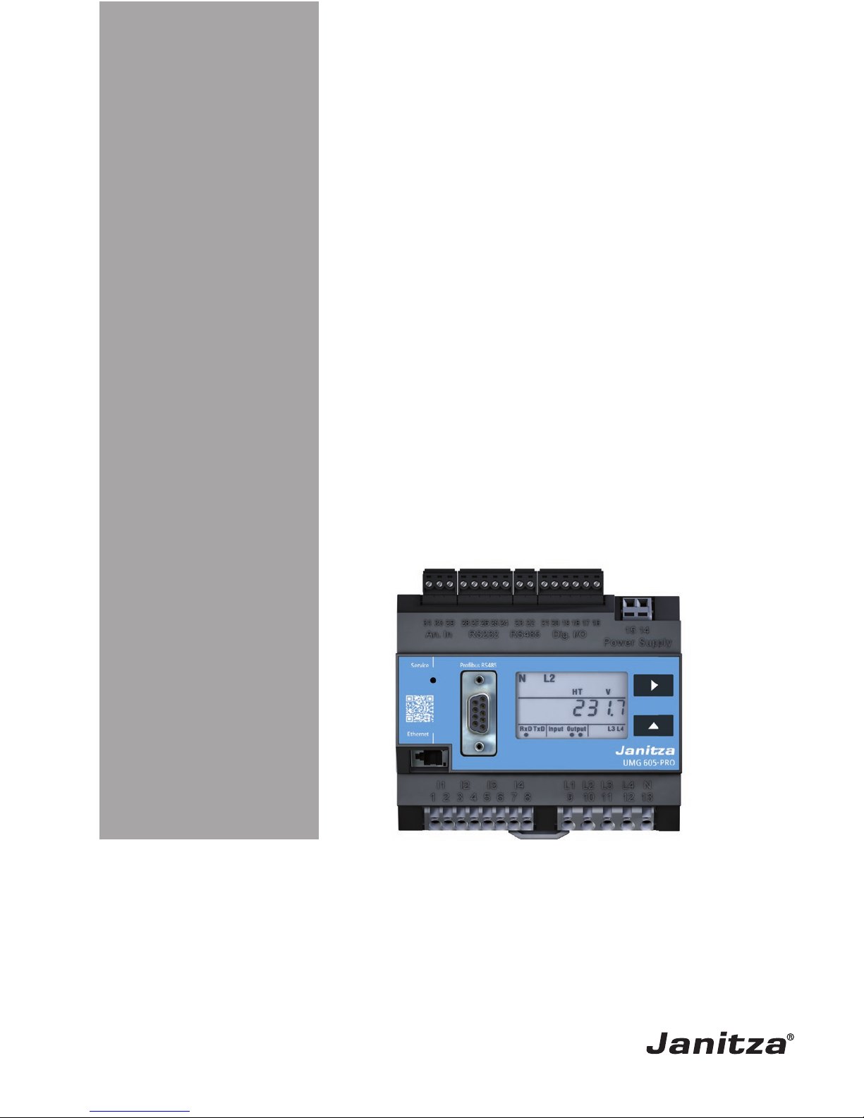
Power Quality Analyser
UMG 605-PRO
User manual and technical data
Part no. 33.03.126
Janitza electronics GmbH
Vor dem Polstück 6
D-35633 Lahnau
Support tel. +49 6441 9642-22
Fax +49 64 41 9642-30
e-mail: info@janitza.com
Internet: http://www.janitza.com
www.janitza.com
A B
Page 2

UMG 605-PRO
www.janitza.de
I
1. Contents
1. General 1
1. 1 Disclaimer 1
1. 2 Copyright notice 1
1. 3 Technical changes 1
1. 4 Declaration of conformity 1
1. 5 Comments on the manual 1
1. 6 Meaning of symbols 1
2. Safety 3
2. 1 Safety information 3
2. 2 Safety measures 3
2. 3 Qualified staff 4
3. Proper use 5
3. 1 Inspection on receipt 5
3. 2 Scope of delivery 6
3. 3 Available accessories 6
4. Product description 7
4. 1 Measuring process 7
4. 2 Network failure detection 7
4. 3 Usage concept 7
4. 4 GridVis® network analysis software 7
4. 5 Features 8
4. 6 Product overview 9
4. 7 Installation location 10
5. Network systems 11
5. 1 Three-phase 4-conductor systems 12
5. 2 Three-phase 3-conductor systems 12
5. 3 Rated voltages 13
Page 3

www.janitza.de
UMG 605-PRO
II
6. Installation 15
6. 1 Disconnectors 15
6. 2 Supply voltage 15
6. 3 Measured voltage 16
6. 4 Frequency measurement 16
6. 5 Current measurement 17
6. 5. 1 Ammeter 18
6. 5. 3 Direct measurement 18
6. 5. 2 Total current measurement 18
6. 5. 4 Current direction 18
6. 6 Connection variants 19
6. 6. 1 Baseline measurement, inputs 1-3 19
6. 6. 2 Supporting measurement, input V4 21
6. 7 Temperature measurement 22
7. Interfaces 23
7. 1 Shielding 23
7. 2 RS232 24
7. 3 RS485 24
7. 3. 2 Cable type 25
7. 3. 1 Termination resistors 25
7. 4 Bus structure 26
7. 5 Profibus 27
7. 5. 1 Connection of the bus wiring 27
8. Digital inputs and outputs 29
8. 1 Digital inputs 29
8. 2 S0 pulse input 30
8. 3 Digital outputs 31
9. Commissioning 33
9. 1 Connecting the supply voltage 33
9. 2 Frequency measurement 33
9. 3 Connecting the measured voltage 33
9. 4 Phase sequence 33
9. 5 Applying the measured current 34
9. 6 Checking the power measurement 34
10. Operation 35
10. 1 Button functions 35
10. 2 Display mode 35
10. 3 Programming mode 36
10. 4 Display password 36
10. 5 Homepage password 36
Page 4

UMG 605-PRO
www.janitza.de
III
11. Configuration 37
11. 1 Measurement 37
11. 1. 1 Baseline measurement (measurement channels 1-3) 37
11. 1. 2 Supporting measurement (measurement channel 4) 37
11. 3 Voltage transformer ratio 38
11. 2 Current transformer ratio 38
11. 4 RS232 configuration 39
11. 5 RS485 configuration 39
11. 6 Ethernet configuration 40
11. 7 Profibus configuration 41
11. 7. 1 Profiles 41
11. 7. 2 Device master file 41
11. 7. 3 Pre-set profiles 42
11. 8 Recording configuration 45
12. System information 47
12. 1 Measurement range exceeded 47
12. 4 Serial number 47
12. 5 Date 47
12. 2 Firmware release 47
12. 3 Time 47
13. Device homepage 49
13. 1 Measured values 50
13. 1. 1 Short overview 50
13. 1. 2 Detailed measured values 51
13. 1. 3 Diagrams 52
13. 1. 4 Events 52
13. 1. 5 Transients 53
13. 2 Power quality 54
13. 3 Apps 55
13. 3. 1 Push Service 55
13. 4 Information 56
13. 4. 1 Device information 56
13. 4. 2 Downloads 56
13. 4. 3 Display 56
14. Service and maintenance 57
14. 1 Repair and calibration 57
14. 2 Front film 57
14. 3 Disposal 57
14. 4 Service 57
14. 5 Battery 57
14. 6 Firmware update 57
Page 5

www.janitza.de
UMG 605-PRO
IV
15. Procedure in the event of faults 59
16. Technical data 61
16. 1 General 61
16. 2 Environmental conditions 61
16. 3 Transport and storage 61
16. 4 Supply voltage 62
16. 5 Protection class 62
16. 6 Digital inputs and outputs 63
16. 7 Temperature measurement input 64
16. 8 Interfaces 65
16. 9 Voltage measurement inputs 66
16. 10 Current measurement inputs 66
16. 11 Function parameters 67
16. 11. 1
Measurement in the frequency range 50/60 Hz 67
16. 11. 2
Measurement in the frequency range of 15 to 440 Hz 68
16. 12 Specifications per IEC 61000-4-30 class S 69
17. Parameter list 71
18. Measured value indications 75
19. Dimension diagrams 77
19. 1 Front view 77
19. 2 Side view 78
20. Connection example 79
21. Short introduction (setting primary current) 81
Page 6

UMG 605-PRO
www.janitza.de
1
1. 1 Disclaimer
Observing the information products
for the devices is the prerequisite for safe
operation and in order to obtain the specified
performance and product features. Janitza
electronics GmbH accepts no liability
for injuries to personnel, property damage
or financial losses arising due to a failure
to comply with the information products.
Ensure that your information products are
accessible and legible.
1. 2 Copyright notice
© 2017 - Janitza electronics GmbH - Lahnau.
All rights reserved.
Duplication, editing, dissemination and other
utilisation, also in part, is prohibited.
All trademarks and the resulting rights are
the property of their respective owners.
1. 3 Technical changes
• Please ensure that your device complies
with the installation manual.
• Please read and understand the
documents enclosed with the product first.
• Keep the documents enclosed with
the product available throughout the entire
service life of the product and pass them
on to subsequent users if applicable.
• Inform yourself of any new device versions
and the associated updates to the
documentation enclosed with the product
at www.janitza.de.
1. 4 Declaration of conformity
For information on the laws, standards and
directives that Janitza electronics GmbH has
applied for the device, see the declaration of
conformity on www.janitza.de.
1. 5 Comments on the manual
We welcome your comments. If anything
in this manual seems unclear, please let us
know by sending us an e-mail to:
info@janitza.de
1. 6 Meaning of symbols
This manual uses the following pictograms:
1. General
Ground wire connection.
Inductive.
The current lags behind the voltage.
Capacitive.
The voltage lags behind the current.
Page 7

www.janitza.de
UMG 605-PRO
2
Page 8
UMG 605-PRO
www.janitza.de
3
Please read this operating manual and all
other publications that must be consulted
to work with this product.
Observe all safety instructions and warnings.
Failure to comply with the instructions can
result in personal injuries and/or damage
to the product.
Any unauthorised changes or use of this
device, which go beyond the mechanical,
electrical or otherwise stated operating
limitations, can result in bodily injury and/or
damage to the product.
Any such unauthorised change constitutes
"misuse" and/or "negligence" according
to the warranty for the product and thus
excludes the warranty for covering possible
damage resulting from this.
The user manual:
• must be read before using the device.
• must be kept throughout the entire service
life of the product and be readily available
for reference.
Follow additional legal and safety regulations
required for the respective application when
using the device.
2. 1 Safety information
Symbols used:
c
This symbol is used as an addition
to the safety instructions and
warns of an electrical hazard.
C
This symbol with the word note
describes:
• Procedures that do not pose
any risk of injures.
• Important information,
procedures or handling steps.
Safety information is highlighted by a warning
triangle and is indicated as follows depending
on the degree of danger:
m
DANGER!
Indicates an imminent danger
that causes severe or fatal
injuries.
m
WARNING!
Indicates a potentially
hazardous situation that can
cause severe injuries or death.
m
CAUTION!
Indicates a potentially
hazardous situation that can
cause minor injuries or damage
to property.
2. Safety
Page 9
www.janitza.de
UMG 605-PRO
4
2. 2 Safety measures
When operating electrical devices, certain
parts of these devices are invariably
subjected to hazardous voltage. Therefore,
severe bodily injuries or damage to property
can occur if they are not handled properly.
m
WARNING!
If the device is not operated
according to the user manual,
protection is no longer ensured
and hazards can be posed
by the device.
2. 3 Qualified staff
This device must only be operated and
repaired by specialised personnel.
Specialised personnel are people who
are qualified to recognise risks and
prevent potential dangers that can be
caused by the operation or maintenance
of the device based on their respective
training and experience.
c
WARNING!
Risk of injury due
to electric voltage!
Severe bodily injuries or death can occur
due to dangerous voltages.
Therefore, note the following:
• Before connecting connections,
earth the device at the ground wire
connection if present.
• Hazardous voltages may be present
in all switching parts that are
connected to the power supply.
• Hazardous voltages may also
be present in the device even after
disconnecting the supply voltage.
• Provide single core conductors with
sleeves.
• Only connect screw-type terminals
with a matching number of pins and
of the same type.
• De-energise the system before
starting work.
Page 10
UMG 605-PRO
www.janitza.de
5
3. 1 Inspection on receipt
The prerequisites of faultless, safe operation
of this device are proper transport and proper
storage, set-up and installation, as well
as careful operation and maintenance.
Packing and unpacking must be carried out
with customary care without the use of force
and only using suitable tools. The devices
should be visually checked for flawless
mechanical condition.
Please check the delivered items
for completeness before you start installing
the device.
If it can be assumed that risk-free operation
is no longer possible, the device must be
immediately put out of operation and secured
against being put back into operation again.
It can be assumed that risk-free operation is
no longer possible if the device, for example:
• has visible damage,
• no longer works despite the mains power
supply being intact,
• has been exposed to prolonged
adverse conditions (e.g. storage outside
the permissible climate limits without
being adapted to the room climate,
condensation, etc.) or rough handling
during transportation (e.g. falling from
a height, even if there is no visible external
damage, etc.)
3. Proper use
C
NOTE!
All supplied options and versions
are described on the delivery note.
C
NOTE!
The installation and commissioning
manual also describes options
that are not supplied as standard.
C
NOTE!
All screw-type terminals included
in the scope of delivery are attached
to the device.
Page 11

www.janitza.de
UMG 605-PRO
6
3. 2 Scope of delivery
Number Part no. Designation
1 52.16.xxx
1)
UMG 605-PRO
1 33.03.337 Installation manual
1 33.03.351 “GridVis software” quick guide
1 10.01.807 Screw-type terminal, pluggable, 2-pin
1 10.01.808 Screw-type terminal, pluggable, 3-pin
1 10.01.809 Screw-type terminal, pluggable, 5-pin
1 10.01.810 Screw-type terminal, pluggable, 6
1 89.10.051 Slotted screwdriver (0.40 x 2 mm), ESD
1 08.01.505 2m patch cable, twisted, grey (UMG PC/switch connection)
1 52.00.008 RS485 termination resistor, 120 ohms
1)
For the item number, see the delivery note
Part no. Designation
21.01.058 CR2032 lithium battery, 3 V (approval according to UL 1642)
08.02.427 RS232, connection cable (UMG604-PRO - PC), 2 m, 5-pin
3. 3 Available accessories
Page 12

UMG 605-PRO
www.janitza.de
7
The device is intended for:
• measuring power quality according
to EN61000-4-30 in building installations,
on distribution units, circuit breakers
and busbar trunking systems.
• measuring measured voltages and currents
that derive from the same network.
• measurements in low voltage networks
where rated voltages of up to 300 V and
surge voltages of overvoltage category III
can occur.
• installation in fixed switching cabinets
or small installation distributors. It can
be installed in any position.
• current measurement, for which it is
provided with external ../1 A or ../5 A
current transformers.
• use in 2, 3 and 4-conductor networks
and in TN and TT networks.
• measurements in medium and highvoltage networks via current and voltage
transformers only.
The measurement results can be displayed,
read out and further processed via
the device's interfaces.
4. 1 Measuring process
The device measures continuously
and calculates all effective values over
a 200 ms interval.
The device measures the real effective
value (TRMS) of the voltages and currents
connected to the measurement inputs.
4. 2 Network failure detection
Network failure detection is carried
out via the voltage measurement inputs.
The selection of
voltage measurement inputs can be
configured using the GridVis® software.
The device bridges the following network
failures on the auxiliary voltage input:
• Supply voltage: 230 V AC
• Bridging time: max. 80 ms
4. Product description
C
NOTE!
Use the parameter list from “17.
Parameter list” for configuration
on the device and use the Modbus
address list on www.janitza.de for
configuration via a serial interface
4. 3 Usage concept
You can program and call up the measured
values via many routes using the device:
• Directly on the device via 2 buttons and
the display
• Using the GridVis® programming software
• Using the device homepage
• Using the Modbus protocol. You
can modify and call up the data using
the Modbus address list. The list can
be called up from www.janitza.de.
This user manual only describes how
to operate the device using the 2 buttons.
The GridVis® programming software has
its own "online help" system.
4. 4 GridVis® network analysis
software
You can use the GridVis® network analysis
software that is available at www.janitza.
de to program the device and read out
data. To do this, a PC must be connected
to the device via a serial interface (RS485/
Ethernet).
You can use the GridVis® network analysis
software to:
• program the device.
• configure and read out recordings.
• save the data to a database.
• display measured values graphically.
• program customer-specific applications.
Page 13

www.janitza.de
UMG 605-PRO
8
4. 5 Features
General
• Installation on a 35 mm DIN rail
• LCD display and operation via 2 buttons
• 4 voltage and 4 current measurement inputs
• 1 temperature measurement input
• 2 digital outputs and 2 digital inputs
• RS485 interface (Modbus RTU, Modbus master, BACnet (optional))
• RS232 interface (Modbus slave)
• Profibus DP/V0
• Ethernet (web server, e-mail, BACnet (optional))
• Suitable for installation in installation distributors
• Working temperature range -10 °C to +55 °C
• Analysis and evaluation in accordance with DIN EN50160 with the GridVis®
programming software that is supplied as standard
• Data logger / event store (128 MB flash drive)
• Capture events such as overvoltages, voltage dips, network failures
and overcurrent
Measurement
• Measurement of the power quality in accordance with DIN EN61000-4-30:2009
class S
• Measurement in IT, TN and TT networks
• Measurement of the harmonics and interharmonics (Uln, Ull, I) in accordance with
DIN EN61000-4-7
• Flicker measurement in accordance with DIN EN61000-4-15:2011 Class F3
• Measurement of ripple control signals (U, I, P, Q)
• Continuous sampling of the voltage and current measurement inputs
• Capture transients >50 µs and store up to 16,000 sampling points
• Capturing more than 2400 measured values per measurement cycle (200 ms)
• Fourier analysis 1st to 63rd Harmonics for Ull, Uln, I, P (consumption/delivery)
and Q (ind./capacitive)
• Temperature measurement
• Active energy; measurement uncertainty in accordance with DIN EN62053-22,
class 0.5 S for ../5A converter
• Reactive energy; measurement uncertainty in accordance with DIN EN62053-23,
class 2
• Programming separate applications in Jasic
Page 14

UMG 605-PRO
www.janitza.de
9
4. 6 Product overview
1
7
2
8
3
11
10
9
4
5
6
12
1 RS232 interface
2 Temperature measurement input
3 Hidden service button
4 Profi bus interface
5 Ethernet interface
6 Current measurement inputs I1 to I4
7 RS485 interface
8 Digital inputs / outputs
9 Supply voltage
10 Button 1
11 Button 2
12 Voltage measurement inputs L1 to L4
Fig. Front view of UMG605-PRO
Page 15
www.janitza.de
UMG 605-PRO
10
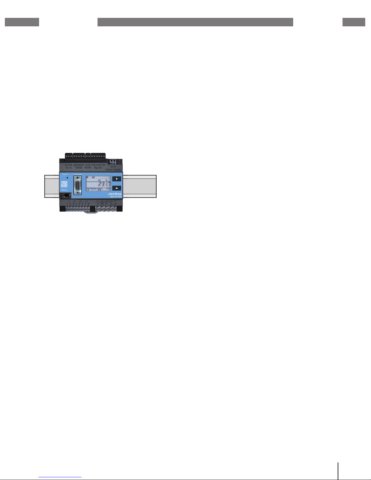
4. 7 Installation location
The device can be installed in switching
cabinets or in small installation distributors
in accordance with DIN 43880
.
It is assembled on a 35 mm mounting rail
in accordance with DIN EN 60715. It can
be installed in any position.
Fig. Front view of UMG 605-PRO on mounting rail
Page 16
UMG 605-PRO
www.janitza.de
11
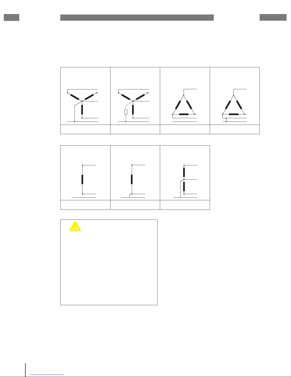
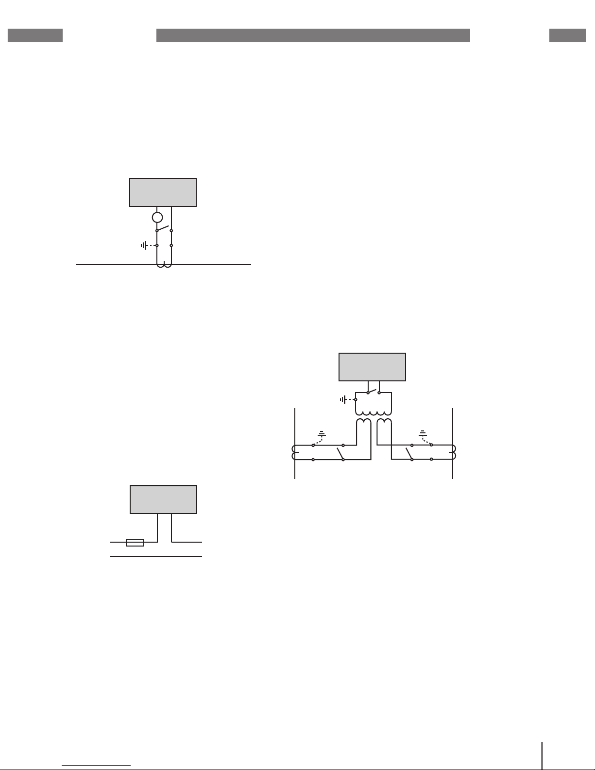
5. Network systems
Three-phase four-
conductor systems
with earthed neutral
conductor
Three-phase four-
conductor systems
with non-earthed neutral
conductor (IT networks)
Three-phase threeconductor systems
not earthed
Three-phase threeconductor systems
with earthed phase
L1
L2
L3
EE
N
E
L1
L2
L3
E
N
R
L1
L2
L3
EE
L1
L2
L3
EE
E
L1
L2
L3
E
N
R
L1
L2
L3
EE
L1
L2
L3
EE
L1
L2
L3
EE
L1
L2
L3
EE
L1
L2
L3
EE
U
L-N
/ U
L-L
277 VLN / 480 VLL
U
L-N
/ U
L-L
277 VLN / 480 VLL
U
L-L
480 VLL
U
L-L
480 VLL
Dual-phase two-conductor
systems
not earthed
Single-phase two-
conductor systems
with earthed neutral conductor
Separated single-phase
three-conductor system
with earthed neutral conductor
The device can be
used:
• in 2-, 3and 4-conductor
networks (TN, TT
and IT networks).
• in domestic and
industrial settings.
L1
L2
L3
EE
N
E
L1
L2
L3
E
N
R
L1
L2
L3
EE
L1
L2
EE
L
N
EE
L1
L2
L3
EE
L1
L2
N
EE
E
L1
L2
L3
E
N
R
L1
L2
L3
EE
L
N
EE
L1
L2
L3
EE
L1
L2
N
EE
L1
L2
L3
EE
L1
L2
L3
EE
L1
L2
N
EE
U
L-L
480 VLL
U
L-N
480 VLN
U
L-N
/ U
L-L
277 VLN / 480 VLL
Suitable network systems and maximum rated voltages (DIN EN 61010-1/A1):
c
WARNING!
Risk of injury due
to electric voltage!
If the device is subjected to measurement
voltage surges higher than the permissible
overvoltage category, safety-relevant
insulations in the device can be damaged,
which means that the product’s safety can
no longer be guaranteed.
Only use the device in environments
in which the permissible measurement
voltage surge is not exceeded.
Page 17
www.janitza.de
UMG 605-PRO
12
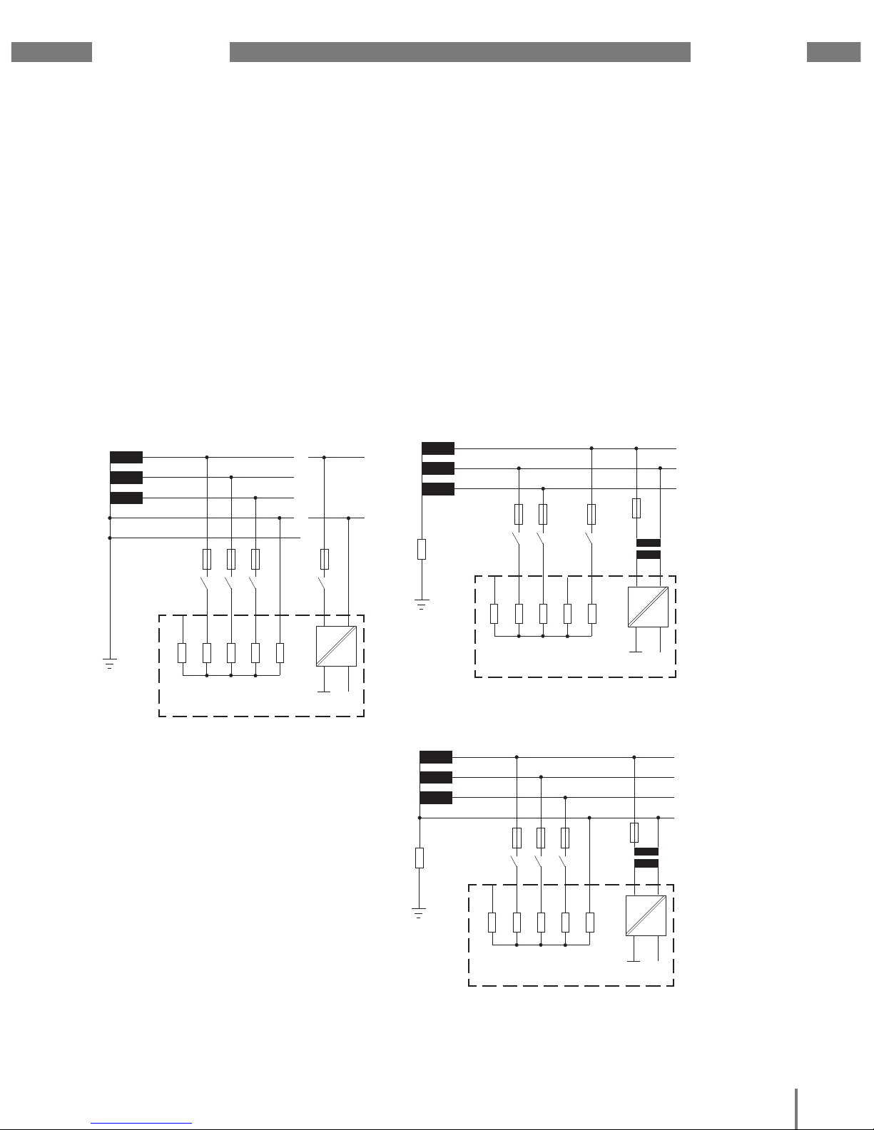
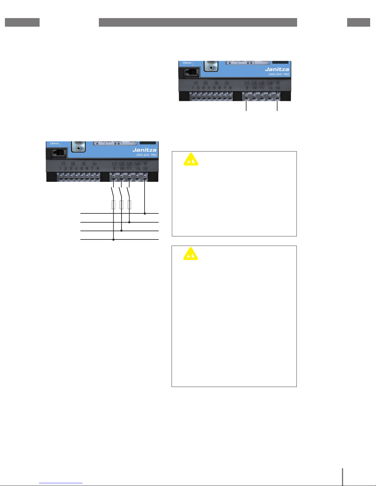
5. 1 Three-phase 4-conductor systems
The device can be used in three-phase
4-conductor systems (TN, TT networks)
(50 Hz, 60 Hz) with an earthed neutral
conductor. The bodies of the electrical
system are earthed.
The voltage between phase and neutral
conductor may be a maximum of 300 V AC.
UMG605-PRO
Earthing of
the system
DC
AC/DC
PE
230/400V 50/60Hz
L2
L3
N
L1
Auxiliary supply
Voltage measurement
4M
4M
4M
4M
L1 L3L2 N
4M
L4
N
L1
240V
50/60Hz
5. 2 Three-phase 3-conductor systems
The device can be used in non-earthed threephase 3-conductor systems (IT network).
The voltage between phase and phase may
be a maximum of 480 V AC (50 Hz, 60 Hz).
The IT network is not earthed at the neutral
point of the voltage generator. The bodies
of the electrical system are earthed. Earthing
via a high ohm impedance is permitted.
IT networks are only permitted in certain
systems with their own transformers or
generators.
230/400V 50/60Hz
UMG605-PRO
Earthing of
the system
DC
AC/DC
L2
L3
N
L1
Auxiliary supply
4M
4M
4M
4M
L1
L3L2 N
4M
L4
Impedance
Voltage measurement
400V 50/60Hz
DC
AC/DC
L2
L3
Auxiliary supply
Voltage measurement
4M
4M
4M
4M
L1
L3L2
4M
L4
Earthing of
the system
Impedance
L1
UMG605-PRO
N
Fig. Schematic diagram, UMG 605-PRO in a TN network
Fig. Schematic diagram, UMG 605-PRO in an IT network with N
Fig. Schematic diagram, UMG 605-PRO in an
IT network without N.
Page 18
UMG 605-PRO
www.janitza.de
13
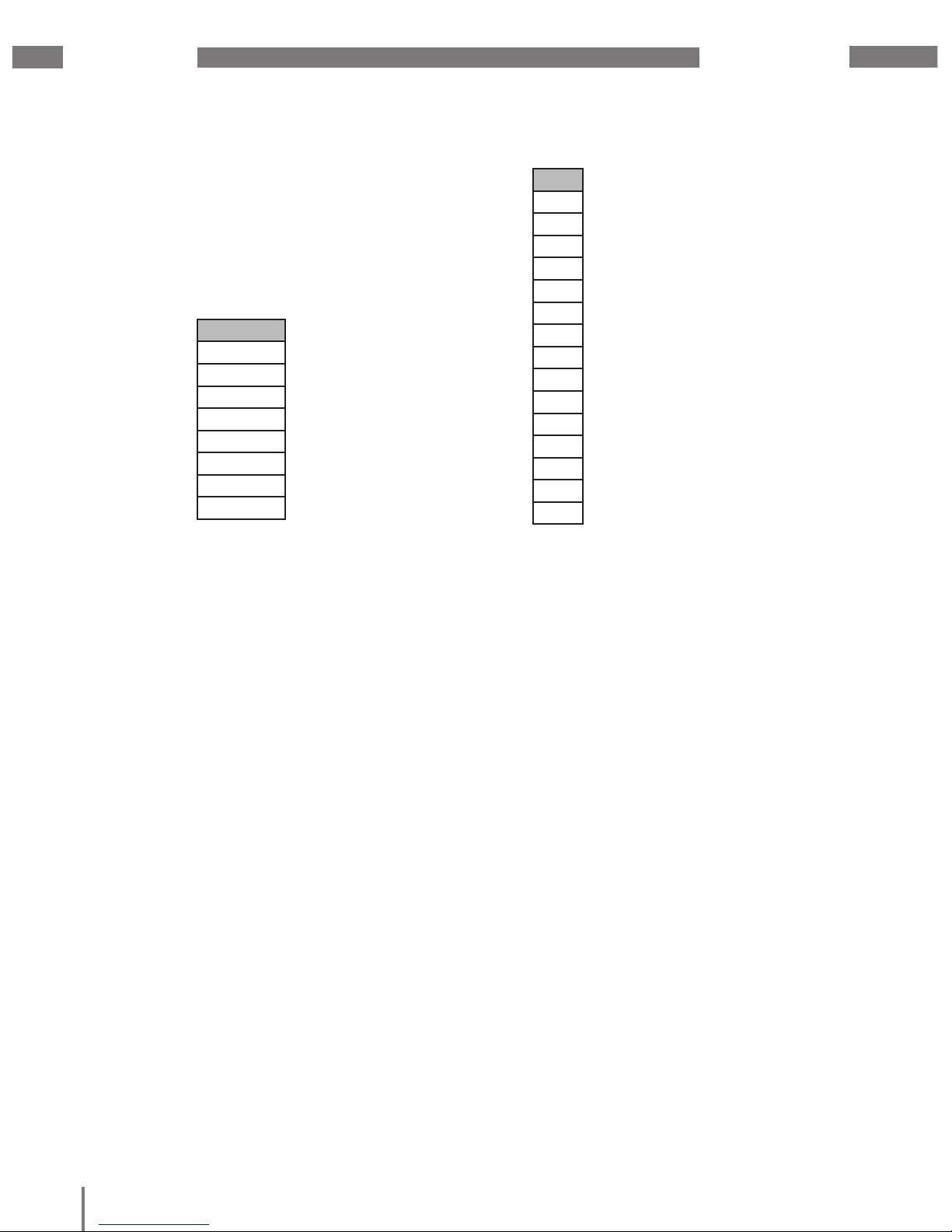
5. 3 Rated voltages
The following illustrations show lists of
networks and the corresponding rated
network voltages in which the device can be
used.
U
L-N
/ U
L-L
66 V / 115 V
120 V / 208 V
127 V / 220 V
220 V / 380 V
230 V / 400 V
240 V / 415 V
260 V / 440 V
277 V /480 V
U
L-L
66V
115V
120V
127V
200V
230V
240V
260V
277V
347V
380V
400V
415V
440V
480V
Fig. Table of suitable
rated voltages in a three-phase 4-conductor network
Fig. Table of suitable
rated voltages in a three-phase 3-conductor network
Page 19

www.janitza.de
UMG 605-PRO
14
Page 20
UMG 605-PRO
www.janitza.de
15
6. Installation
6. 1 Disconnectors
During building installation, provide a suitable
disconnector in order to disconnect
the device from the current and voltage.
• Install the disconnector close to the device
so that it is easily accessible to the user.
• Label the switch as a disconnection device
for this device.
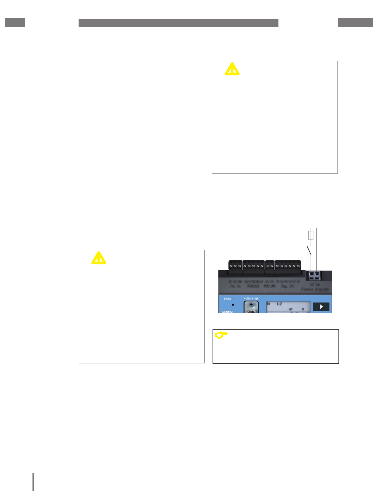
6. 2 Supply voltage
The device requires supply voltage
to operate.
Before connecting the supply voltage, ensure
that the voltage and frequency correspond to
the details on the rating plate!
The connection lines for the supply voltage
must be protected using a UL-listed fuse
or a circuit breaker.
c
WARNING!
Risk of injury due
to electric voltage!
Severe bodily injuries or death can occur
due to
• touching bare or stripped wires that are
live,
• device inputs that are dangerous
to touch.
Therefore, note the following:
• De-energise your system before
starting the work!
• The inputs for the supply voltage are
hazardous if touched!
m
CAUTION!
Damage to property
due to not observing
the connection conditions
Failure to observe the connection conditions
can damage or destroy your device.
Therefore, note the following:
• Adhere to the specifi cations for voltage
and frequency on the rating plate.
• Connect the supply voltage via a fuse
in accordance with the technical data.
• Do not connect the supply voltage
to the voltage transformers.
Supply voltage
Uh
Isolation device
Fuse
Fig. Example connection for the supply voltage Uh.
C
NOTE!
Devices that can be operated with DC
voltage are protected against polarity
reversal.
Page 21
www.janitza.de
UMG 605-PRO
16
6. 3 Measured voltage
The device is designed to measure AC
voltage in 300 V networks, in which
overvoltages of category III can occur.
The device can only determine measured
values if measured voltage of >10 Veff is
present on at least one voltage measurement
input.
c
WARNING!
Risk of injury due
to electric voltage!
Severe bodily injuries or death can occur
due to a failure to observe the connection
conditions for the voltage measurement
inputs.
Therefore, note the following:
• Do not use the device for voltage
measurement in SELV circuits.
• Connect the voltages higher than
the#permitted network rated voltages
using voltage transformers.
• The voltage measurement inputs
on the device are dangerous
if touched!
• Also install a disconnector for the
measured voltage as described in “6. 1
Disconnectors”.
c
CAUTION!
Malfunction due to
incorrect connection
If the device is connected incorrectly,
incorrect measured values may be returned.
Therefore, note the following:
• Measured voltages and currents must
derive from the same network.
• The device is not suitable
for measuring DC voltage.
L3
N
L1
L2
Disconnectors
Fig.23.1 Connection example: Voltage measurement via
short circuit-proof measurement wires
Note the following when selecting
the measurement wires:
• Use measurement wires that are suitable
for 300 V to earth and 520 V conductor
to conductor.
• Fuse the normal measurement wires using
an overcurrent protection device.
• Route normal short circuit-proof
measurement wires via a disconnector.
L
N
Fig. Voltage measurement input with connected phase L
and neutral conductor N
6. 4 Frequency measurement
The device is suitable for measurements in
networks in which the fundamental oscillation
of the voltage is in the range of 15 to 440 Hz.
In order to determine the mains frequency
automatically, a voltage L1-N of greater than
10 Veff must be applied to voltage input V1.
The mains frequency is only measured
on the measurement inputs of the baseline
measurement (V1, V2, V3).
Page 22
UMG 605-PRO
www.janitza.de
17
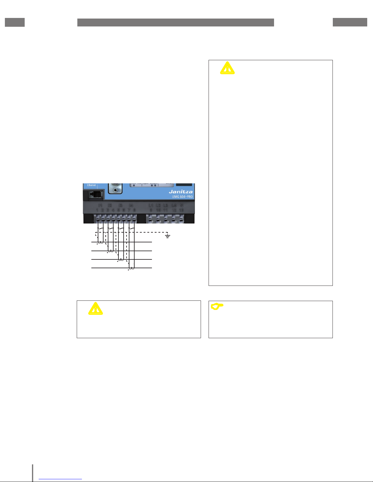
6. 5 Current measurement
The device:
• is intended for connecting current
transformers with secondary currents
of ../1 A and ../5 A.
• does not measure DC.
• has current measurement inputs that
are continuously loaded with 6 A or loaded
with 100 A for 1 second.
m
WARNING!
Risk of injury due
to electric voltage
on current transformers!
On current transformers that are operated
open on the secondary side,
high voltage peaks that are dangerous to
touch can occur, which can cause severe
bodily injuries or death.
Therefore, note the following:
• Avoid operating the current
transformers open.
• Short circuit all unloaded current
transformers.
• Connect the earthing connections provided
on the current transformer to the earth.
• You must short circuit the secondary
connections on the current transformer
before interrupting the power supply.
• If a test switch, which automatically
short-circuits the secondary wires
of the current transformer is available,
it is suffi cient to set this to the "Test"
position as long as the short-circuiting
device has been checked beforehand.
• Ensure that the attached screwtype terminal is affi xed to the device
suffi ciently using the two screws.
• Safe open-circuit current transformers
are also dangerous to touch when they
are operated open.
C
NOTE!
It is not necessary to confi gure
a connection schematic
for measurement inputs L4 and I4.
Consumer
L3
L1
L2
N
S1
S2
S1
S2
S1
S2
S1
S2
Fig.
Current measurement via current transformers
connection example.
m
WARNING!
Risk of injury due
to electric voltage!
Current measurement inputs are
dangerous to touch.
Page 23
www.janitza.de
UMG 605-PRO
18
6. 5. 1 Ammeter
If you wish to measure the current not only
with the UMG but rather with an ammeter
too, connect the ammeter to the UMG
in series.
6. 5. 2 Total current measurement
F
or a summation measurement via
two current transformers, first set their
total transformation ratio on the device.
For information on setting the current
transformer ratios, see “11. 2 Current
transformer ratio”.
Example:
The current is measured via two current
transformers. Both current transformers
have a transformation ratio of 1000 / 5 A.
The summation measurement is performed
using a 5+5 / 5 A total current transformer.
The device must then be set up as follows:
Primary current: 1000 A + 1000 A = 2000 A
Secondary current: 5 A
UMG
S2
I
S
1
P1
P2
Einspeisung 1
Supply 1
Einspeisung 2
Supply 2
1P1
1P2
(K)
(L)
(k)
(l)
1S
2
1S1
1S1 1S2 2S1 2S2
2S1
2S2
(k)
(l)
(K)
(L)
2P
1
2P2
Verbraucher A
Consumer A
Verbraucher B
Consumer B
Fig. Circuit diagram with additional ammeter switched
in series
UMG
S2
I
S
1
Einspeisung
Supply
Verbraucher
Consumer
A
(k)S
1 S2(l)
P
2(L)(K)P1
Fig. Example for current measurement via a total current
transformer
Fig. Example of direct current measurement.
6. 5. 3 Direct measurement
Rated currents of up to 5 A can be measured
directly on the device. When doing so, note
that each current measurement input can be
continuously loaded with 6 A or loaded with
max. 100 A for 1 second.
The device does not have integrated
protection for current measurement.
Therefore, provide a 6 A line protection fuse
or automatic circuit breaker as protection
against overcurrent when installing.
UMG
S2
I
S
1
Einspeisung
Supply
Verbraucher
Consumer
6. 5. 4 Current direction
You can correct the current direction directly
on the device or via the existing serial
interfaces for each phase individually.
If incorrectly connected, a subsequent
re-connection of the current transformer
is not required.
Page 24
UMG 605-PRO
www.janitza.de
19
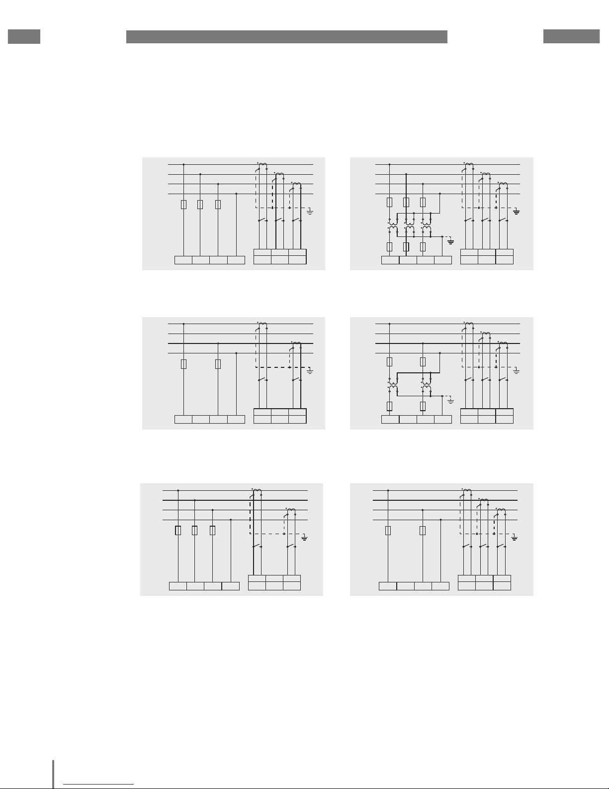
6. 6 Connection variants
6. 6. 1 Baseline measurement, inputs 1-3
Four-conductor connection
Fig. Measurement via 3 voltage transformers in a three-
phase 4-conductor network with asymmetric loading.
Fig. Measurement in a three-phase 4-conductor network
with asymmetric loading.
Fig. Measurement via 2 voltage transformers in a three-
phase 4-conductor network with asymmetric loading.
Fig. Measurement in a three-phase 4-conductor network
with symmetric loading.
Fig. Measurement in a three-phase 4-conductor network
with asymmetric loading.
Fig. Measurement via 2 current transformers in a three-
phase 3-conductor network with symmetric loading.
L1
L2
L3
N
L1 L2 L3 N
4w 3m
I1 I2 I3
S1 S2 S1 S2 S1 S2
L1
L2
L3
N
L
1 L2 L3 N
4w 3m
hv
I1 I2 I3
S1 S2 S1 S2 S1 S2
L1
L2
L3
N
L
1 L2 L3 N
4w 2i
I1 I2 I3
S1 S2 S1 S2 S1 S2
L1
L2
L3
N
L1 L2 L3 N
4w 3m
hv
I1 I2 I3
S1 S2 S1 S2 S1 S2
L1
L2
L3
N
L
1 L2 L3 N
4w 2i
I1 I2 I3
S1 S2 S1 S2 S1 S2
L1
L2
L3
N
L
1 L2 L3 N
4w 3m
I1 I2 I3
S1 S2 S1 S2 S1 S2
L1
L2
L3
N
L
1 L2 L3 N
4w 3m
hv
I
1 I2 I3
S1 S2 S1 S2 S1 S2
L1
L2
L3
N
L
1 L2 L3 N
4w 2i
I1 I2 I3
S1 S2 S1 S2 S1 S2
L1
L2
L3
N
L1 L2 L3 N
4w 2m
I1 I2 I3
S1 S2 S1 S2 S1 S2
L1
L2
L3
N
L
1 L2 L3 N
4w 2u
hv
I
1 I2 I3
S1 S2 S1 S2 S1 S2
L1
L2
L3
N
L
1 L2 L3 N
4w 2u
I1 I2 I3
S1 S2 S1 S2 S1 S2
L1
L2
L3
N
L
1 L2 L3 N
4w 3m
hv
I
1 I2 I3
S1 S2 S1 S2 S1 S2
L1
L2
L3
N
L
1 L2 L3 N
4w 2i
I1 I2 I3
S1 S2 S1 S2 S1 S2
L1
L2
L3
N
L1 L2 L3 N
4w 2u
hv
I1 I2 I3
S1 S2 S1 S2 S1 S2
L1
L2
L3
N
L
1 L2 L3 N
4w 2u
I1 I2 I3
S1 S2 S1 S2 S1 S2
L1
L2
L3
N
L1 L2 L3 N
4w 2i
I1 I2 I3
S1 S2 S1 S2 S1 S2
L1
L2
L3
N
L
1 L2 L3 N
4w 2i
I1 I2 I3
S1 S2 S1 S2 S1 S2
L1
L2
L3
N
L1 L2 L3 N
4w 2u
I1 I2 I3
S1 S2 S1 S2 S1 S2
Page 25
www.janitza.de
UMG 605-PRO
20
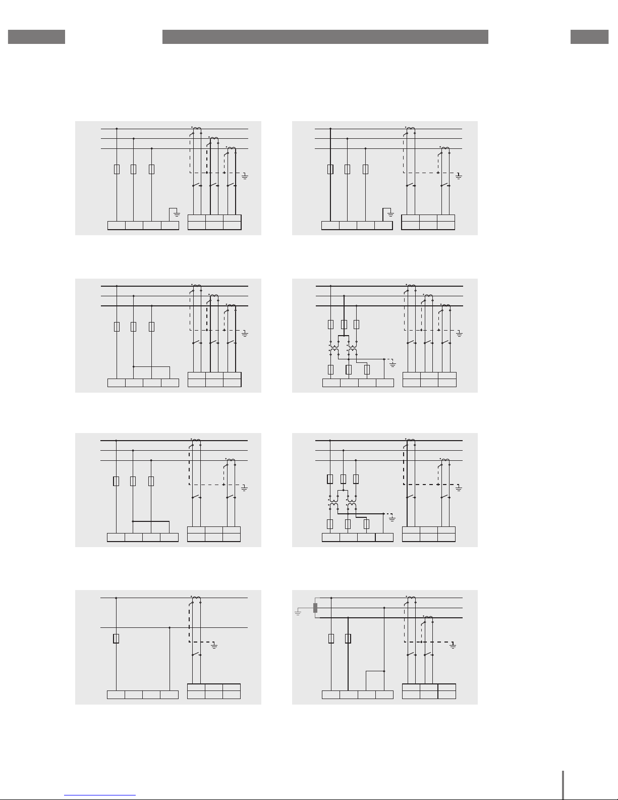
Three-conductor connection
Fig. Measurement in a three-phase 3-conductor network
with asymmetric loading.
Fig. Measurement in a three-phase 3-conductor network
with asymmetric loading.
Fig. Measurement in a three-phase 3-conductor network
with asymmetric loading.
Fig. Measurement in a three-phase 3-conductor network
with asymmetric loading.
Fig. Measurement in a single-phase 3-conductor
network. I3 and U3 are not calculated and set to zero.
Fig. Measurement in a three-phase 3-conductor network
with asymmetric loading.
Fig. Measurement in a three-phase 3-conductor network
with asymmetric loading.
Fig. Measurement of one phase in a three-phase
4-conductor network.
L1
L2
L3
L1 L2 L3 N
3w 3m
I1 I2 I3
S1 S2 S1 S2 S1 S2
L1
L2
L3
L
1 L2 L3 N
3w 2i
I1 I2 I3
S1 S2 S1 S2 S1 S2
L1
L2
L3
L
1 L2 L3 N
3w 2m
I1 I2 I3
S1 S2 S1 S2 S1 S2
L1
L2
L3
L1 L2 L3 N
3w 2i
I1 I2 I3
S1 S2 S1 S2 S1 S2
L1
L2
L3
L
1 L2 L3 N
3w 2m
I1 I2 I3
S1 S2 S1 S2 S1 S2
L1
L2
L3
L
1 L2 L3 N
3w 2m
hv
I
1 I2 I3
S1 S2 S1 S2 S1 S2
L1
N
L
1 L2 L3 N
2w 1m
I1 I2 I3
S1 S2 S1 S2 S1 S2
L1
L2
L3
L
1 L2 L3 N
3w 3m
I1 I2 I3
S1 S2 S1 S2 S1 S2
L1
L2
L3
L
1 L2 L3 N
3w 2i
I1 I2 I3
S1 S2 S1 S2 S1 S2
L1
L2
L3
L
1 L2 L3 N
3w 2m
I1 I2 I3
S1 S2 S1 S2 S1 S2
L1
L2
L3
L1 L2 L3 N
3w 2u
I1 I2 I3
S1 S2 S1 S2 S1 S2
L1
L2
L3
L
1 L2 L3 N
3w 2u
hv
I
1 I2 I3
S1 S2 S1 S2 S1 S2
L1
N
L
1 L2 L3 N
2w 1m
I1 I2 I3
S1 S2 S1 S2 S1 S2
L1
L2
L3
L
1 L2 L3 N
3w 2i
I1 I2 I3
S1 S2 S1 S2 S1 S2
L1
L2
L3
L
1 L2 L3 N
3w 2m
I1 I2 I3
S1 S2 S1 S2 S1 S2
L1
L2
L3
L
1 L2 L3 N
3w 2m
hv
I1 I2 I3
S1 S2 S1 S2 S1 S2
L1
L2
L3
L1 L2 L3 N
3w 2u
hv
I1 I2 I3
S1 S2 S1 S2 S1 S2
L1 L2 L3 N
2w 2m
I1 I2 I3
S1 S2 S1 S2 S1 S2
L1
L2
L1
L2
L3
L1 L2 L3 N
3w 2m
I1 I2 I3
S1 S2 S1 S2 S1 S2
L1
L2
L3
L
1 L2 L3 N
3w 2m
hv
I
1 I2 I3
S1 S2 S1 S2 S1 S2
L1
L2
L3
L1 L2 L3 N
3w 2m
hv
I1 I2 I3
S1 S2 S1 S2 S1 S2
L1
N
L1 L2 L3 N
2w 1m
I1 I2 I3
S1 S2 S1 S2 S1 S2
L1
L2
L3
L
1 L2 L3 N
3w 2m
I1 I2 I3
S1 S2 S1 S2 S1 S2
L1
L2
L3
L
1 L2 L3 N
3w 2m
hv
I
1 I2 I3
S1 S2 S1 S2 S1 S2
L1 L2 L3 N
2w 2m
I1 I2 I3
S1 S2 S1 S2 S1 S2
L1
L2
L1
L2
L3
L
1 L2 L3 N
3w 2m
hv
I
1 I2 I3
S1 S2 S1 S2 S1 S2
L1 L2 L3 N
2w 2m
I1 I2 I3
S1 S2 S1 S2 S1 S2
L1
L2
Page 26
UMG 605-PRO
www.janitza.de
21
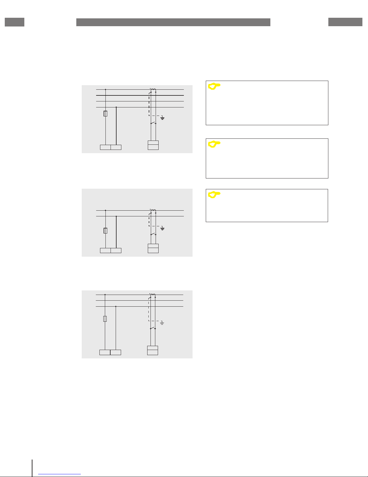
6. 6. 2 Supporting measurement, input V4
Three-conductor connection
Fig. Measurement via a current transformer in a three-
phase 4-conductor network with symmetric loading.
Fig. Measurement via a current transformer in a three-
phase 3-conductor network with symmetric loading.
Fig. Measurement via a current transformer.
L1
L2
L3
N
L4 N
4w 1m
I4
S1 S2
L1
L2
L3
L
4 N
4w 1m
I4
S1 S2
L1
L2
L3
L4 N
4w 1m
I4
S1 S2
L1
L2
L3
N
L
4 N
4w 1m
I4
S1 S2
L1
L2
L3
L
4 N
4w 1m
I4
S1 S2
L
L4 N
2w 1n
I4
S1 S2
N
C
NOTE!
If the baseline measurement (inputs
V1-V3) is connected to a three-phase
3-conductor network, the supporting
measurement (input V4) can no longer
be used as a measurement input.
C
NOTE!
For measurement with the supporting
measurement (V4), a voltage must be
connected to the baseline measurement
for frequency determination.
C
NOTE!
Measured voltages and measured
currents must derive from the same
network.
Page 27
www.janitza.de
UMG 605-PRO
22
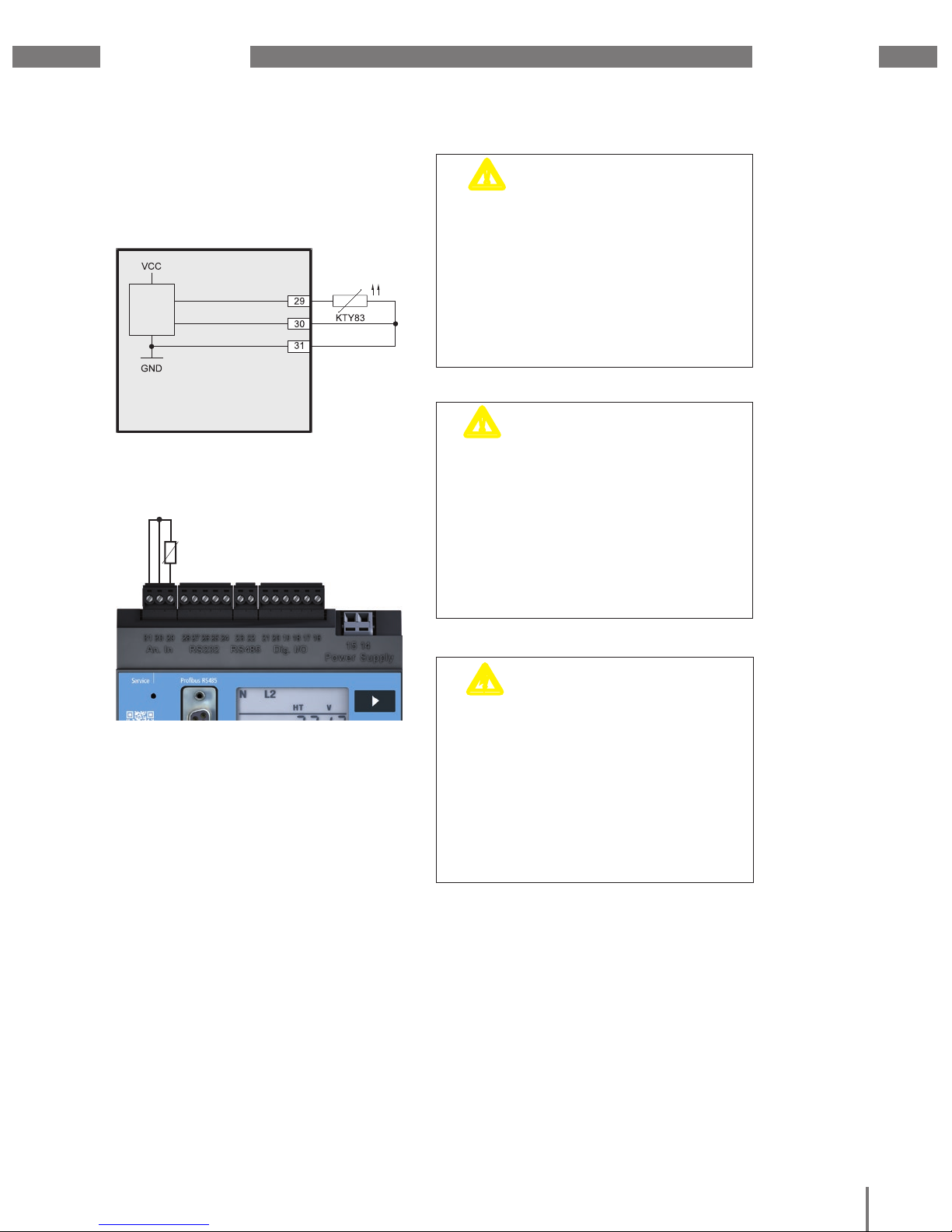
KTY83
6. 7 Temperature measurement
The device has a temperature measurement
input that is designed for a maximum total
burden of 4 kOhm.
Fig.42.1 Example, temperature measurement with
a KTY83.
UMG 605-PRO
Analog Input
m
CAUTION!
Transmission errors and
damage to property due
to electrical faults
If the line is longer than 30 m, there
is an increased probability of transmission
errors and damage to the device due
to atmospheric discharge.
Use a shielded cable to connect
to the temperature sensor.
m
CAUTION!
Risk of injury due
to electric voltage!
Insuffi cient insulation of the operating
equipment at the temperature measurement
input to the mains supply circuits can cause
the temperature measurement input
and interfaces RS232 and RS485 to
be hazardous to touch.
Ensure that there is reinforced or double
insulation to the mains supply circuits!
Fig. Connecting temperature sensor to the measurement
input
c
WARNING!
Risk of injury due
to electric voltage!
RS232, RS485 and the temperature
measurement input are not galvanically
separated from each other.
Therefore, be aware that hazardous
voltages on the inputs that are not
galvanically separated may have effects
on the other connections.
Page 28

UMG 605-PRO
www.janitza.de
23
7. Interfaces
The device has the following interfaces:
• RS232
• RS485
• Ethernet
• Profibus
All interfaces can be used simultaneously.
7. 1 Shielding
A twisted, shielded cable should be used
for connections via the RS232 and RS485
interfaces.
Earth the shields of all cables that lead
to the cabinet and at the cabinet entry.
Connect the screens over a generous area
and in a manner that will conduct well,
to a low-noise earth.
Gather the cables mechanically above
the earthing clamp in order to avoid damage
due to cable movements.
Use suitable cable glands to feed the cables
into the cabinet, for example, armoured
conduit couplings.
Fig. Shielding procedure at cabinet entry.
Cable
Strain relief
Screen braid of the cable
Earthing clamp
Noiseless ground
c
WARNING!
Risk of injury due
to electric voltage!
RS232, RS485 and the temperature
measurement input are not galvanically
separated from each other. The Profibus
and Ethernet are functionally insulated from
each other and the remaining interfaces.
Therefore, be aware that hazardous
voltages on the inputs that are not
galvanically separated may have effects
on the other connections.
Page 29

www.janitza.de
UMG 605-PRO
24
7. 2 RS232
You can use an RS232 connection cable
to connect the device to a PC.
The achievable distance between two
devices with RS232 interfaces depends
on the cable used and the baud rate.
The maximum cable length that can
be connected is 30 m!
As a guideline, if the transmission rate
is 9600 Baud, a distance of 15 m to 30 m
should not be exceeded.
The permissible ohmic load must be greater
than 3 kOhm and the capacitive load caused
by the transmission line must be lower than
2500 pF.
Fig. Plug arrangement for the PC connection cables
(item no. 08 02 427).
D-sub, 9-pin,
Receptacle
Mini Combicon
5-pin
PC
Com1
Fig. Example, connecting a UMG605-PRO to a PC
via the RS232 interface.
7. 3 RS485
In the UMG605, the RS485 interface
is designed as a
2-pin plug contact.
RS485 bus
A
B
A
B
B
A
Fig. RS485 interface, 2 pin plug contact
RS485 bus
A
B
B
A
Fig. RS485 interface, 2-pin plug contact with
termination resistor (item no. 52.00.008).
120Ω
Page 30

UMG 605-PRO
www.janitza.de
25
7. 3. 1 Termination resistors
The cable is terminated with resistors (120 Ohm
1/4 W) at the beginning and at the end of a segment.
The UMG605-PRO does not contain any
termination resistors.
Correct
Incorrect
Terminal strip in the cabinet.
Device with RS485 interface.
(without termination resistor)
Device with RS485 interface.
(with termination resistor on the device)
7. 3. 2 Cable type
CAT cables are not suitable for bus wiring.
Instead, we recommend the following cable
types:
• Unitronic Li2YCY(TP) 2x2x0.22 (from Lapp
Kabel)
• Unitronic BUS L2/FIP 1x2x0.64 (from Lapp
Kabel)
The maximum cable length is 1200 m at a
baud rate of 38.4 k.
m
WARNING!
Risk of injury due
to electric voltage!
Temperatures of up to 80 °C can occur
on the connections if there are high
measured currents.
Therefore, use lines that are designed for
an operating temperature of at least 80 °C
Page 31

www.janitza.de
UMG 605-PRO
26
7. 4 Bus structure
• All devices are connected in a bus
structure (line).
• Up to 32 participants can be connected
together in a single segment.
• The cable is terminated with resistors
at the beginning and at the end
of a segment.
• If there are more than 32 participants,
repeaters (amplifiers) must be used
to connect the individual segments.
• Devices for which the bus connection
is switched on must be under current.
• It is recommended that the master
be placed at the end of a segment.
• If the master is replaced with a bus
connection, the bus must be switched off.
• Replacing a slave with a bus connection
that is either switched off or de-energised
can destabilise the bus.
• Devices that are not connected
to the bus can be replaced without
destabilising the bus.
Fig. Bus structure illustration
SlaveSlaveSlave
Slave
Slave Slave Repeater
Slave Slave Slave Slave
Master
Speisung notwendig / power supply necessary
Busabschluß eingeschaltet / bus terminator onT
T
T
T
T
Page 32

UMG 605-PRO
www.janitza.de
27
7. 5 Profi bus
The UMG 605-PRO is equipped with
a Profi bus connection that is designed as
a 9-pin DSUB receptacle.
For the connection, we recommend a
"SUBCON-Plus-Profi B/AX/SC" 9-pin Profi bus
connector from Phoenix.
You can order this from us using Janitza item
number 13.10.539.
Fig. UMG605-PRO with Profi bus interface.
Fig. Profi bus connector with termination resistors.
7. 5. 1 Connection of the bus wiring
The inbound bus wiring is connected
to terminals 1A and 1B.
The bus wiring for the next device in line
is connected to terminals 2A and 2B.
If there are no subsequent devices in
the line, the bus wiring must be terminated
with a resistor (switch to ON). With the switch
set to ON, terminals 2A and 2B are switched
off for further continuing bus wiring.
UMG 605-PRO
Profibus connector
Termination resistors
(external)
Screw-type terminals
D-Sub,
9-pin,
Receptacle
D-Sub,
9-pin,
Receptacle
Other
Profibus
participants
Page 33

www.janitza.de
UMG 605-PRO
28
Page 34

UMG 605-PRO
www.janitza.de
29
8. Digital inputs and outputs
8. 1 Digital inputs
The device has 2 digital inputs to which you
can connect one signal generator each.
An input signal is detected on a digital input
if a voltage of at least 10 V and maximum
28 V DC is applied.
The fl owing current is at least 1 mA and
a maximum of 6 mA.
Pay attention to the supply voltage's polarity!
m
CAUTION!
Transmission errors and
damage to property due
to electrical faults
If the line is longer than 30 m, there is
an increased probability of transmission
errors and damage to the device due
to atmospheric discharge.
Use a shielded cable for connection
to the digital inputs.
+
-
24V
DC
Fig. Connection example of digital inputs.
Fig. Example for the connection of external switch
contacts S1 and S2 to digital inputs 1 and 2.
+
-
S2
S1
24V
=
UMG 605-PRO
Digital inputs 1-2
4.4k
19
Digital
Input 1
3.9V
3.9V
20
21
Digital
Input 2
4.4k
m
CAUTION!
Damage to property due
to connection errors
Ensure that:
• the supply voltage is DC voltage.
• the supply voltage has the right polarity.
• the height of the voltage is at least 10 V
and a maximum of 28 V.
Page 35

www.janitza.de
UMG 605-PRO
30
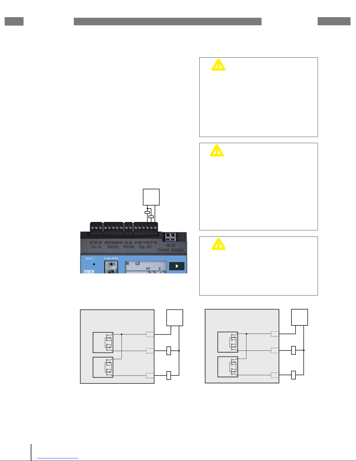
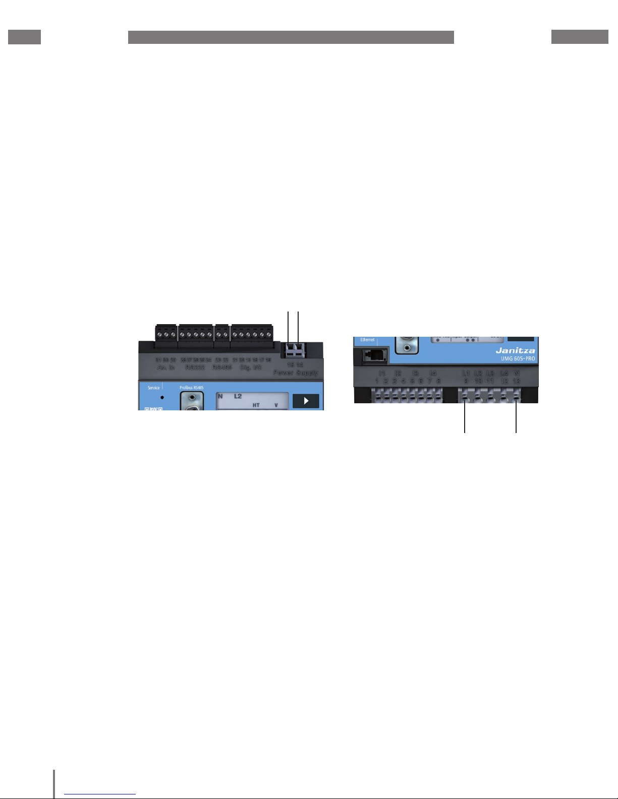
8. 2 S0 pulse input
You can also connect S0 pulse transducers
per DIN EN62053-31 to each UMG 605-PRO
with inputs for 24 V.
You only require external auxiliary voltage
of 20 to 28V DC and an external 1.5 kOhm
resistor each.
+
-
1.5k
S0 pulse transducer
24V
DC
Fig. UMG 605-PRO with inputs for 24V. Example with
S0 pulse transducer.
Fig. UMG 605-PRO with inputs for 24V and an S0 pulse
transducer on digital input 2.
S0 pulse
transducer
1.5k
+
-
UMG 605-PRO
Digital inputs 1-2
4k
19
Digital
Input 1
3.9V
3.9V
4k
20
21
Digital
Input 2
24V
=
Page 36
UMG 605-PRO
www.janitza.de
31
8. 3 Digital outputs
The device has 2 transistor switching
outputs that are galvanically separated from
the analysis electronics using opto couplers.
The digital outputs:
• can switch DC or AC loads.
• can switch loads depending on the supply
voltage's polarity.
m
CAUTION!
Transmission errors
and damage to property
due to electrical faults
If the line is longer than 30 m, there
is an increased probability of transmission
errors and damage to the device due
to atmospheric discharge.
Use a shielded cable for connection
to the digital outputs.
24V
DC
+
-
Fig. Connection example of digital outputs.
Fig. Connection of a DC voltage relay to the digital
outputs.
16
17
Digital
Output 1
UMG 605-PRO
Digital outputs
K2 K1
+
-
24V
DC
18
Digital
Output 2
Fig. Connection of an AC voltage relay to the digital
outputs.
16
17
Digital
Output 1
UMG 605-PRO
Digital outputs
K2 K1
~
24V
AC
18
Digital
Output 2
~
m
CAUTION!
Damage to property due
to connection errors
The digital outputs are not short-circuit
proof! Connection errors can therefore
cause damage to the connections.
Ensure that the wiring is correct when
connecting the outputs.
m
CAUTION!
Measurement errors when
using as a pulse output
When using the digital outputs as pulse
outputs, measurement errors may arise due
to the residual ripple.
Therefore, use a mains adapter for
the supply voltage for the digital inputs
and outputs, which has a residual ripple
of less than 5% of the supply voltage.
Page 37

www.janitza.de
UMG 605-PRO
32
Page 38
UMG 605-PRO
www.janitza.de
33
9. Commissioning
Before commissioning, clear any content
that may be present on the power meters,
min./max. values or recordings due
to the production process.
9. 1 Connecting the supply voltage
After connecting the supply voltage,
the text “Start up” is shown on the display.
Approximately two to six seconds later,
the device switches to the fi rst measured
value indication.
If no display appears, check whether
the power supply voltage is within the rated
voltage range.
Fig.23.1 Example connection for the supply voltage Uh.
Supply voltage
(see rating plate)
9. 2 Frequency measurement
In order to measure the frequency, at least one
voltage measurement path (L-N) must have a
measured voltage of greater than 10 V.
Only detected frequencies in the range
of 15 Hz to 440 Hz are used for measurement
on the current and voltage measurement
inputs.
9. 3 Connecting the measured voltage
After connecting the measured voltages,
the measured values displayed by
the device for the L-N and L-L voltages
must correspond to those on the voltage
measurement input.
If a voltage transformer factor is
programmed, it must be taken into
consideration for the comparison.
At least one phase (L) and the neutral
conductor (N) must be connected to the
voltage measurement input for measurement.
A measured voltage of greater than 10 Veff
must be present on at least one of the voltage
measurement inputs so that the device can
determine the mains frequency.
L N
9. 4 Phase sequence
Check the direction of the rotating fi eld
voltage in the measured value indication
of the device. A “right-hand” rotation fi eld
usually exists.
Page 39

www.janitza.de
UMG 605-PRO
34
9. 5 Applying the measured current
The device:
• is intended for connecting current
transformers with secondary currents
of ../1 A and ../5 A.
• does not measure DC.
• has current measurement inputs that are
continuously loaded with 6 A or loaded
with 100 A for 1 second.
Proceed as follows to connect measured
current to the device:
1. Connect the currents to be measured
to voltage measurement inputs I1 to I4.
2. Short circuit all current transformer outputs
except for one.
3. Compare the currents displayed by
the device with the applied current.
• Bearing in mind the current transformer
conversion ratio, the current displayed
by the device must correspond
to the current input.
• The device must display approx. zero
amperes in the short circuited current
measurement inputs.
The current transformer ratio is factory-set
to 5/5A and must be adapted to the current
transformer used if necessary.
9. 6 Checking the power measurement
Short-circuit all current transformer outputs
except for one and check the displayed
power outputs.
The device may only display one power
output in the phase with a non-shortcircuited current transformer input. If this
is not the case, check the connection of
the measured voltage and the measuringcircuit current.
If the power figure is correct but the power
sign is negative, connections S1(k) and S2(l)
on the current transformer may be mixed up
or they are supplying active energy back to
the network.
Page 40

UMG 605-PRO
www.janitza.de
35
10. Operation
In order to make it easier to install and
commission the device without a PC, it has
a display, as well as buttons 1, 2
and the Service button.
Important parameters such as the current
transformer and the device address are
listed in the parameter list in section “17.
Parameter list” and can be programmed
directly on the device.
When operating, the device differentiates
between:
• Display mode and
• Programming mode
10. 1 Button functions
Press the button for a short time:
• scroll forwards
• digit/value +1
Press the button for a long time:
• scroll backwards
• digit/value -1
Press and hold both buttons simultaneously
for around 1 second:
• Switch between display mode and
programming mode.
The device is operated using buttons 1 and 2.
The service button is only for use by trained
service employees.
Fig. Front view of UMG 605 -PRO control element
10. 2 Display mode
After the power returns, the device
is in display mode.
In display mode, you can use buttons 1
and 2 to scroll through the measured value
indications.
• Use button 1 to select the phase for the
measured values.
• Use button 2 to scroll between the
measured values for current, voltage,
power, etc.
The factory default setting for the measured
value indications is shown in section “17.
Parameter list”.
N L1
RxD TxD
V
L1 L2 L3 L4
Input Output
Fig. Display example for "Display mode". Measured value
indication U
L1-N
= 230.0 V.
Fig. Display example for rotation fi eld and frequency.
RxD TxD
L1 L2 L3 L4
Input Output
Hz
C
NOTE!
You can reconfi gure the functions
of the buttons and the selection
of the values to be displayed using
the GridVis® software as a Jasic
program. (see www.janitza.de)
Page 41

www.janitza.de
UMG 605-PRO
36
10. 3 Programming mode
You view and change the most important
settings required to operate the device
in programming mode.
The addresses for the most important
settings are provided in section “17.
Parameter list”.
You can make further settings in the GridVis®
software supplied.
Pressing and holding buttons 1 and 2
simultaneously for approx. 1 second
takes you to programming mode after
the password prompt.
If no display password has been set up, you
are taken directly to the first programming
menu.
Programming mode is indicated on screen
by the text "PRG". The digit in the address
flashes. If you are in programming mode and
no button is pressed around 60 seconds or
if buttons 1 and 2 are pressed simultaneously
for around 1 second, the device returns to
display mode.
Fig. Display example for "Programming mode", address
000 with a content of 5,000. Fig. Request window for the display password
Address Content
PRG
10. 4 Display password
To make it harder to accidentally modify
the programming data on the device,
you can program a 4-character display
password. No display password is factoryset. No display password is requested
in the factory default setting.
10. 5 Homepage password
You can password-protect access to the device’s
homepage. No homepage password is factory-set.
The device differentiates between 3 password
modes for the homepage password:
• 0 = The homepage password is
not requested.
• 2 = Changes to the configuration and
the measured values display require
the password to be entered once.
• 128 = Each change to the configuration
requires the password to be entered again
C
NOTE!
If you no longer remember your
password, you can only change
it using the GridVis® software.
(see www.janitza.de)
Content
PRG
Addr. Contents
500 Display password
0 = The password is
not requested.
501 Homepage,
password mode
502 Homepage password
Fig. Excerpt from the parameter list.
Page 42

UMG 605-PRO
www.janitza.de
37
11. Configuration
11. 1 Measurement
The device has 4 measurement channels for voltage
measurement (V1 - V4 against Vref) and 4 measurement
channels for current measurement (I1 to I4).
Measured voltage and measured current
for the measurement channels 1-4 must
derive from the same network.
11. 1. 1 Baseline measurement
(measurement channels 1-3)
The baseline measurement uses measurement
channels 1-3. Use measurement channels 1-3
for measurement in three-phase systems.
You can choose one of 14 measurement
switches for the baseline measurement. The
relevant connection illustrations are provided
in section “6. 6 Connection variants”.
You can use parameter address “110” to set
the selected measurement switch.
Selectable measurement switches:
• 0 = 4w3m (factory default setting)
• 1 = 4w2m
• 2 = 4w2u
• 3 = 4w2i
• 4 = 3w3m
• 5 = 3w2m
• 6 = 3w2u
• 7 = 3w2i
• 8 = 2w2m
• 9 = 2w1m
• 10 = 4w3m_hv
• 11 = 4w2u_hv
• 12 = 3w2u_hv
• 13 = 3w2m_hv
Address Content
PRG
Fig. Display example; measurement switch for the baseline
measurement, address 110 with a content of 0.
11. 1. 2 Supporting measurement
(measurement channel 4)
The supporting measurement only uses
measurement channel 4.
Use measurement channel 4 when measuring
in single-phase systems or in three-phase
systems with symmetrical loads.
The frequency setting and the setting
for the relevant voltage are pulled automatically
from the baseline measurement settings.
You can choose one of 3 measurement
switches for the supporting measurement.
The relevant connection illustrations are
provided on page 23.
You can use parameter address “111” to set
the selected measurement switch.
Address Content
PRG
Selectable measurement switches:
• 0 = 2w1n (factory default setting)
• 1 = 3w1m
• 2 = 4w1m
Fig. Display example; measurement switch for the supporting
measurement, address 111 with a content of 0.
Page 43

www.janitza.de
UMG 605-PRO
38
11. 2 Current transformer ratio
You can set the current transformer ratio
for the baseline measurement using
addresses 000 and 001.
You can use addresses 010 and 011
to set the current transformer ratio for
the supporting measurement.
A current transformer ratio of 5 A / 5 A is
factory-set for all 4 current transformer inputs
in the factory.
Address Current transformer
values
Baseline measurement
000 L1 L2 L3 (primary)
001 L1 L2 L3 (secondary)
Supporting measurement
010 L4 (primary)
011 L4 (secondary)
Address
Content
PRG
Fig. Example; Current transformer (primary) for the baseline
measurement, address 000 with a content of “5“.
11. 3 Voltage transformer ratio
You can use addresses 002 and 003 to set
the voltage transformer ratio for the baseline
measurement.
You can use addresses 012 and 013
to set the voltage transformer ratio for
the supporting measurement.
A voltage transformer ratio of 400 V / 400 V is
factory-set for all 4 voltage transformer inputs
in the factory.
Address Current transformer
values
Baseline measurement
002 L1 L2 L3 (primary)
003 L1 L2 L3 (secondary)
Supporting measurement
012 L4 (primary)
013 L4 (secondary)
Fig. Example; voltage transformer (primary) for the baseline
measurement, address 002 with a content of “400“.
Address Content
PRG
Page 44

UMG 605-PRO
www.janitza.de
39
11. 4 RS232 configuration
The following data must be programmed
to operate the RS232 interface:
• baud rate,
• operating mode.
For information on the factory default setting
and the setting ranges, see the parameter list
in the appendix.
Address Settings
201 Baud rate, RS232
0 = 9600Bit/s
1 = 19200Bit/s
2 = 38400Bit/s
3 = 57600Bit/s
4 =115200Bit/s
204 RS232. mode
0 = Modbus RTU/slave
3 = Debug
6 = SLIP
(for internal use only)
Address Settings
200 Device address (1 to 255)
applies to Modbus and Profibus
1 = factory default setting
202 Baud rate, RS485
0 = 9600Bit/s
1 = 19200Bit/s
2 = 38400Bit/s
3 = 57600Bit/s
4 =115200Bit/s
5 = 921600Bit/s
203 RS485, mode
0 = Modbus RTU/slave
1 = Modbus RTU/master
2 = Gateway transparent
11. 5 RS485 configuration
The following data must be programmed
to operate the RS485 interface:
• device address,
• baud rate,
• operating mode.
For information on the factory default setting
and the setting ranges, see the parameter list
in the appendix.
Page 45

www.janitza.de
UMG 605-PRO
40
11. 6 Ethernet configuration
Static IP address
In simple networks with no DHCP server, the network address must be set right
on the device itself.
BootP
BootP enables the device to be integrated
into an existing network fully automatically.
However, BootP is an older protocol and
does not provide the scope of functions
provided by DHCP.
DHCP mode
DHCP makes it possible integrate a
UMG 604-PRO into an existing network
fully automatically without the need
for any additional configuration. When
started, the device automatically obtains
the IP address, the subnet mask and
the gateway from the DHCP server.
The device is factory-set to the “DHCP
client”.
Zeroconf
Zeroconf enables a UMG 605PRO to
be automatically integrated (IP address
assignment) into an existing network without
a DHCP server.
m
CAUTION!
Damage to property due to
incorrect network settings
Incorrect network settings can cause faults
in the IT network.
Obtain information from your network
administrator about the correct settings
for your device.
Fig. Connection example, the UMG 604PRO and PC
require a static IP address.
Switch
Patch cable Patch cable
PC UMG
605PRO
Fig. Connection example, the UMG 604PRO and PC are
automatically assigned an IP address by a DHCP server.
Patch
Cable
Patch cable Patch cable
DHCP
server
PC UMG
605PRO
Switch
Address Settings
205 DHCP mode
0 = static IP
1 = BootP
2 = DHCP client
3 = Zeroconf
300 IP address, xxx --- --- --301 IP address, --- xxx --- --302 IP address, --- --- xxx --303 IP address, --- --- --- xxx
304 IP mask, xxx --- --- --305 IP mask, --- xxx --- --306 IP mask, --- --- xxx ---
307 IP mask, --- --- --- xxx
310 IP gateway, xxx --- --- --311 IP gateway, --- xxx --- --312 IP gateway, --- --- xxx ---
313 IP gateway, --- --- --- xxx
Page 46

UMG 605-PRO
www.janitza.de
41
11. 7 Profibus configuration
11. 7. 1 Profiles
The device can manage 16 Profibus profiles,
each with a maximum of 128 data bytes.
The first data byte of the PLC's output range
always contains the profile number of the
Profibus profile requested by the UMG.
To request a Profibus profile, write the profile
number to the first byte of the PLC's output
range.
All system variables and global variables
1)
can
be individually scaled and converted into one
of the following formats:
• 8, 16, 32 bit integer with and without sign.
• 32 or 64 bit float format.
• Big or little endian2).
1) Global variables are variables that the user
defines in Jasic and are available to each interface in the UMG604
2 ) Big endian = high byte before low byte.
Little endian = low byte before high byte.
11. 7. 2 Device master file
The device master file, abbreviated
as the GSD file, describes the Profibus
characteristics of the UMG. The GSD
file is required by the configuration program
of the PLC.
The device master file for your device
is called “u6050c2d.GSD” and is available
on the Janitza homepage.
PLC output box
1. Byte = profile number
As of the 2nd
byte, variables for
the UMG 605PRO follow.
PLC
PLC input box
1. Byte = return signal
from the profile number
As of the 2nd byte,
the variables requested by
the UMG 605-PRO follow.
UMG 605-PRO
Fig. Block diagram for data exchange between PLC and
UMG 605-PRO.
Fig. Excerpt from the parameter list.
Address Settings
200 Device address (1 to 255)
applies to Modbus and Profibus
1 = factory default setting
Page 47

www.janitza.de
UMG 605-PRO
42
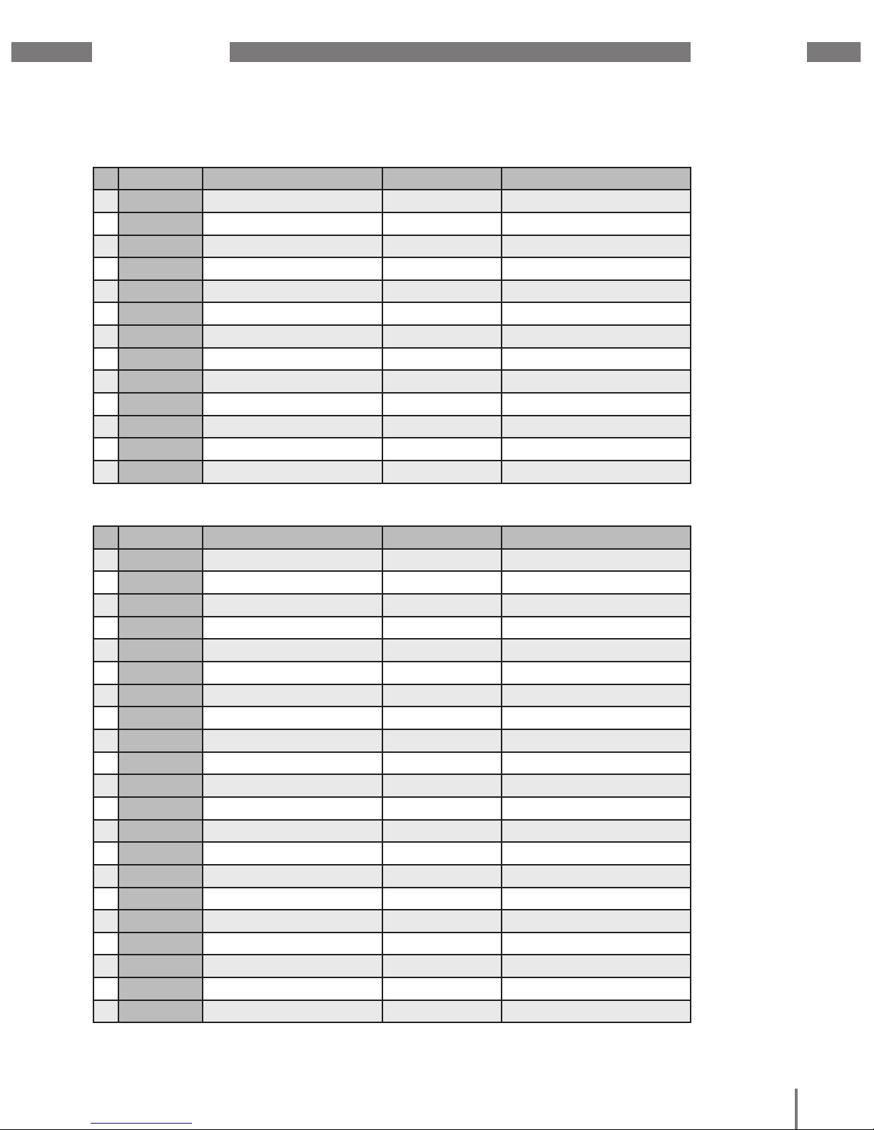
11. 7. 3 Pre-set profiles
Profibus profile number 0
Byte index Value type Value format Scaling
1 1 Voltage L1-N Float 1
2 5 Voltage L2-N Float 1
3 9 Voltage L3-N Float 1
4 13 Voltage L4-N Float 1
5 17 Voltage L2-L1 Float 1
6 21 Voltage L3-L2 Float 1
7 25 Voltage L1-L3 Float 1
8 29 Current L1 Float 1
9 33 Current L2 Float 1
10 37 Current L3 Float 1
11 41 Current L4 Float 1
12 45 Active power L1 Float 1
13 49 Active power L2 Float 1
14 53 Active power L3 Float 1
15 57 Active power L4 Float 1
16 61 Cosphi (math.) L1 Float 1
17 65 Cosphi (math.) L2 Float 1
18 69 Cosphi (math.) L3 Float 1
19 73 Cosphi (math.) L4 Float 1
20 77 Frequency Float 1
21 81 Total active power L1-L4 Float 1
22 85 Total reactive power L1-L4 Float 1
23 89 Total apparent power L1-L4 Float 1
24 93 Total cosphi (math.) L1-L4 Float 1
25 97 Total effective current L1-L4 Float 1
26 101 Total active energy L1-L4 Float 1
27 105 Ind. Total reactive energy L1-L4 Float 1
28 109 THD voltage L1 Float 1
29 113 THD voltage L2 Float 1
30 117 THD voltage L3 Float 1
Page 48

UMG 605-PRO
www.janitza.de
43
Profibus profile number 1
Byte index Value type Value format Scaling
1 1 Voltage L1-N Float 1
2 5 Voltage L2-N Float 1
3 9 Voltage L3-N Float 1
4 13 Voltage L2-L1 Float 1
5 17 Voltage L3-L2 Float 1
6 21 Voltage L1-L3 Float 1
7 25 Current L1 Float 1
8 29 Current L2 Float 1
9 33 Current L3 Float 1
10 37 Active power L1 Float 1
11 41 Active power L2 Float 1
12 45 Active power L3 Float 1
13 49 Cosphi (math.) L1 Float 1
14 53 Cosphi (math.) L2 Float 1
15 57 Cosphi (math.) L3 Float 1
16 61 Frequency Float 1
17 65 Total active power L1-L3 Float 1
18 69 Total reactive power L1-L3 Float 1
19 73 Total apparent power L1-L3 Float 1
20 77 Total cosphi (math.) L1-L3 Float 1
21 81 Total effective current L1-L3 Float 1
22 85 Total active energy L1-L3 Float 1
23 89 Ind. Total reactive energy L1-L3 Float 1
24 93 THD voltage L1 Float 1
25 97 THD voltage L2 Float 1
26 101 THD voltage L3 Float 1
27 105 THD current L1 Float 1
28 109 THD current L2 Float 1
29 113 THD current L3 Float 1
Page 49
www.janitza.de
UMG 605-PRO
44
Profibus profile number 2
Profibus profile number 3
Byte index Value type Value format Scaling
1 1 Total active energy L1-L3 Float 1
2 5 Rel. Total active energy L1-L3 Float 1
3 9 Deliv. Total active energy L1-L3 Float 1
4 13 Total reactive energy L1-L3 Float 1
5 17 Ind. Total reactive energy L1-L3 Float 1
6 21 Total cap. reactive energy L1-L3 Float 1
7 25 Total apparent energy L1-L3 Float 1
8 29 Active energy L1 Float 1
9 33 Active energy L2 Float 1
10 37 Active energy L3 Float 1
11 41 Inductive reactive energy L1 Float 1
12 45 Inductive reactive energy L2 Float 1
13 49 Inductive reactive energy L3 Float 1
Byte index Value type Value format Scaling
1 1 Active power L1 Float 1
2 5 Active power L2 Float 1
3 9 Active power L3 Float 1
4 13 Total active power L1-L3 Float 1
5 17 Current L1 Float 1
6 21 Current L2 Float 1
7 25 Current L3 Float 1
8 29 Total current L1-L3 Float 1
9 33 Total active energy L1-L3 Float 1
10 37 CosPhi (math.) L1 Float 1
11 41 CosPhi (math.) L2 Float 1
12 45 CosPhi (math.) L3 Float 1
13 49 Total CosPhi (math.) L1-L3 Float 1
14 53 Reactive power L1 Float 1
15 53 Reactive power L2 Float 1
16 53 Reactive power L3 Float 1
17 53 Total reactive power L1-L3 Float 1
18 53 Apparent power L1 Float 1
19 53 Apparent power L2 Float 1
20 53 Apparent power L3 Float 1
21 53 Total apparent power L1-L3 Float 1
Page 50

UMG 605-PRO
www.janitza.de
45
11. 8 Recording configuration
2 recordings are pre-configured
in the device’s factory default setting.
Recordings are adjusted and expanded using
the GridVis® software.
Recording 1
The following measured values are recorded
with the time base of 15 minutes:
• Voltage effective L1
• Voltage effective L2
• Voltage effective L3
• Voltage effective L4
• Voltage effective L1-L2
• Voltage effective L2-L3
• Voltage effective L3-L1
• Current effective L1
• Current effective L2
• Current effective L3
• Current effective L4
• Active power L1
• Active power L2
• Active power L3
• Active power L4
• Total active power L1-L3
• Total active power L1-L4
• Reactive power fundamental oscillation L1
• Reactive power fundamental oscillation L2
• Reactive power fundamental oscillation L3
• Reactive power fundamental oscillation L4
• Total reactive power fundamental oscillation
L1-L3
• Total reactive power fundamental oscillation
L1-L4
(The mean value, minimum value, and
maximum value are also recorded for each
measured value.)
Recording 2
The following measured values are recorded
with the time base of 1 hour:
• Active energy drawn L1
• Active energy drawn L2
• Active energy drawn L3
• Active energy drawn L4
• Total active energy drawn L1-L3
• Total active energy drawn L1-L4
• Inductive reactive energy L1
• Inductive reactive energy L2
• Inductive reactive energy L3
• Inductive reactive energy L4
• Total inductive reactive energy L1-L3
• Total inductive reactive energy L1-L4
Page 51

www.janitza.de
UMG 605-PRO
46
Page 52

UMG 605-PRO
www.janitza.de
47
12. System information
12. 1 Measurement range exceeded
If the measurement range is exceeded,
it is displayed as long as this persists and
cannot be acknowledged. The measurement
range is exceeded if at least one of the
four voltage or current measurement inputs
is outside its specified metering range.
If the measurement range is exceeded,
this is shown on the display with “EEEE”.
Symbols L1, L2, L3 and L4 are used to show
the input on which the measurement range
was exceeded. The "V" and "A" symbols
indicate whether the measurement range
has been exceeded in the current or voltage
circuit.
Fig. Measured value indication for the firmware release.
RxD TxD
L1 L2 L3 L4
Input Output
12. 2 Firmware release
Fig. Measured value indication with time.
RxD TxD
L1 L2 L3 L4
Input Output
12. 3 Time
L1 L2 L3 L4
RxD TxD
VA
L1 L2 L3 L4
Input Output
Fig. Measured value indication with measurement range
exceeded.
Fig. Measured value indication with serial number.
RxD TxD
L1 L2 L3 L4
Input Output
12. 4 Serial number
Fig. Measured value indication with date.
RxD TxD
L1 L2 L3 L4
Input Output
12. 5 Date
m
CAUTION!
Damage to property
due to not observing
the connection conditions
Failure to observe the connection conditions
can damage or destroy your device.
Therefore, note the following:
• Adhere to the specifications for voltage
and frequency on the rating plate.
Page 53

www.janitza.de
UMG 605-PRO
48
Page 54
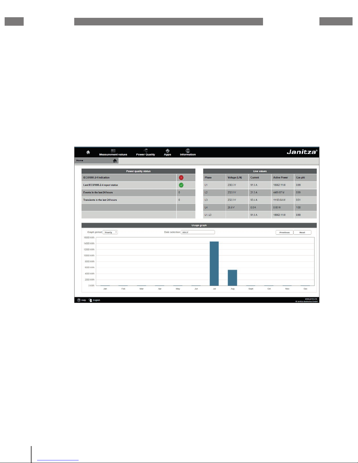
UMG 605-PRO
www.janitza.de
49
13. Device homepage
Your measurement device has an integrated
web server, which has a separate homepage.
You can use this device home page to
access your measurement device from any
end device via a standard web browser.
You can access the homepage for your
device by entering the device’s PI address
in a web browser on your end device. Section
“11. 6 Ethernet configuration” explains how
to connect the device to the internet.
You can do the following here without first
installing any software:
• call historical and current measured
values.
• call the power quality status in an easy
to understand illustration.
• control your device remotely.
• access installed apps.
Fig. Device homepage overview
Page 55

www.janitza.de
UMG 605-PRO
50
13. 1 Measured values
You can use the measured values menu item to call simple and detailed views
of the measured values, and to display individual measured values. The following menu items
are available:
• Short overview
• Detailed measured values
• Diagrams
• Events
• Transients
13. 1. 1 Short overview
The short overview provides you with the most important measured values for each phase,
such as the current voltage values, power values and current strength.
Fig. Short overview of measured values
Page 56

UMG 605-PRO
www.janitza.de
51
13. 1. 2 Detailed measured values
In the overview, you can call extensive information on the following points:
• Voltage
• Current
• Power
• Harmonic oscillations
• Energy
• Peripheral devices (digital inputs/outputs, temperature measurements)
Fig. Detailed overview of measured values
Page 57
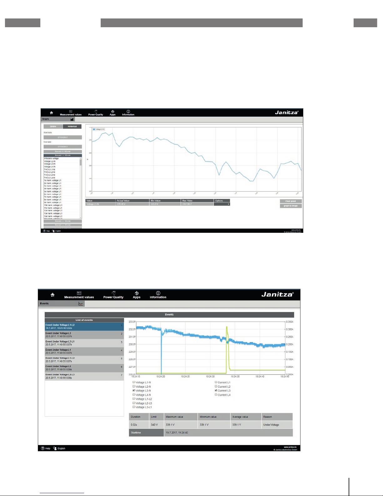
www.janitza.de
UMG 605-PRO
52
13. 1. 3 Diagrams
You can use the “Diagrams” item to access the measured values monitor. The measured
values monitor is a configurable display of current and historical measured values with
automatic scaling. In order to display a graphic of the measured values, drag the required
values from the list on the left edge of the screen into the field in the middle of the screen.
13. 1. 4 Events
You can use events item to display a graphical illustration of the recorded events such
as overcurrent or undervoltage by clicking the relevant event in the list.
Fig. Event records
Fig. Device homepage event records
Page 58

UMG 605-PRO
www.janitza.de
53
13. 1. 5 Transients
The “Transients” area provides a graphic illustration of transients within a date list. Transient
voltages:
• are fast impulse transient effects in electrical networks.
• are unpredictable from a time perspective and have a limited duration.
• are caused by lightning strikes, switching operations or by tripped fuses.
Fig. Transients
Page 59

www.janitza.de
UMG 605-PRO
54
13. 2 Power quality
The “Power quality” section (PQ) provides you with the option of calling the PQ status
in a clear way according to common standards. Here, you have access to permanent
power quality monitoring in accordance with:
• EN 50160 in energy supply networks.
• IEC 61000-2-4 in customer supply networks.
The display is based on the traffic light principle, which makes it easy to detect events
that do not meet the relevant quality requirements without in-depth knowledge.
Fig. IEC 61000-2-4 parameters with traffic-light principle
Page 60

UMG 605-PRO
www.janitza.de
55
13. 3 Apps
You have the option of extending the functions on your device retrospectively by installing
additional apps.
13. 3. 1 Push Service
The push service is an example of an app installed in the factory. The push service sends
measured values directly from the device to a cloud or portal solution chosen by you- such
as the Janitza Energy Portal
Fig. Push Service
Page 61

www.janitza.de
UMG 605-PRO
56
13. 4 Information
13. 4. 1 Device information
You can use the device information menu item to obtain all information and settings that
you can change on the device.
13. 4. 2 Downloads
You can use the downloads item to access the download area on the Janitza homepage.
You can download catalogues and user manuals from here.
13. 4. 3 Display
The display item provides you with the display of your device, which corresponds
to the real display.
You can control the device remotely here by clicking the control buttons using the mouse.
Fig. Operating the UMG 605-PRO via the device homepage
Page 62

UMG 605-PRO
www.janitza.de
57
14. Service and maintenance
The device underwent various safety checks
before delivery and is marked with a seal.
If a device is open, the safety checks must
be repeated. Warranty claims will only
be accepted if the device is unopened.
14. 1 Repair and calibration
Repair work and calibration can be carried
out by the manufacturer only.
14. 2 Front film
The front film can be cleaned with a soft cloth
and standard household cleaning agent.
Do not use acids and products containing
acid for cleaning.
14. 3 Disposal
Observe the national regulations!
If necessary, dispose of individual parts
according to their properties and existing
country-specific regulations, e.g. as:
• Electronic waste
• Plastics
• Metals
or commission a certified disposal company
with scrapping.
14. 4 Service
Should questions arise, which are
not described in this manual, please contact
the manufacturer directly.
We will need the following information from
you to answer any questions:
• device name (see rating plate),
• serial number (see rating plate),
• software release (see measured value
indication),
• measured voltage and supply voltage,
• precise description of the error.
14. 5 Battery
The internal clock is fed from the supply
voltage.
If the supply voltage fails then the clock
is powered by the battery.
The clock provides date and time
information, for the records, min. and max.
values and events, for example.
The life expectancy of the battery is at least
5 years with a storage temperature of +45°C.
The typical life expectancy of the battery is 8
to 10 years.
The device must be opened to change
the battery.
C
NOTE!
If the device has been opened,
a new safety inspection must be
carried out to ensure safe operation.
Warranty claims will only be
accepted if the device is unopened.
14. 6 Firmware update
In order to carry out a firmware update,
connect the device to a computer via
Ethernet and access it using the GridVis®
software.
Open the firmware update wizard by clicking
“Update device” in the “Extras” menu.
Select the relevant update file and carry
out the update.
C
NOTE!
Firmware may not be updated via
the RS485 interface.
Page 63

www.janitza.de
UMG 605-PRO
58
Page 64

UMG 605-PRO
www.janitza.de
59
15. Procedure in the event of faults
Possible fault Cause Remedy
No display External fuse for the power
supply voltage has tripped.
Replace fuses.
Device defective. Send the device to the
manufacturer for repair.
No current display Measured voltage is
not connected.
Connect the measured voltage.
Measurement current is
not connected.
Connect measuring-circuit
current.
Displayed current is too
high or too low
Current measurement in
the wrong phase.
Check connection and correct
if necessary.
Current transformer factor is
incorrectly programmed.
Read out and program the CT
ratio on the current transformer.
Displayed voltage is too
low or too high.
Measurement in the wrong
phase.
Check connection and correct
if necessary.
Voltage transformer incorrectly
programmed.
Read out and program
the voltage transformer ratio
at the voltage transformer.
Voltage displayed is too
low.
Measurement range exceeded. Use voltage transformers.
The peak voltage value
at the measurement input
has been exceeded by
the harmonics.
Attention! Ensure
the measurement inputs are
not overloaded.
“EEEE” and “V”
on the display
The voltage measurement
range has been exceeded.
Check the measured voltage
and install a suitable voltage
transformer if necessary.
“EEEE” and “A”
on the display
The current measurement range
has been exceeded.
Check the measured current
and install a suitable current
transformer if necessary.
Table Procedure in the event of faults, part 1
Page 65

www.janitza.de
UMG 605-PRO
60
Table Procedure in the event of faults, part 2
Possible fault Cause Remedy
“Error CF”
on the display
The calibration data could not
be read.
Send the device to
the manufacturer for inspection
and testing along with
an accurate fault description.
Active power,
consumption/supply
reversed.
At least one current transformer
connection is mixed up/
reversed.
Check connection and correct
if necessary.
A current circuit is assigned
to the wrong voltage circuit.
Check connection and correct
if necessary.
Active power too high
or too low.
The programmed CT ratio
is incorrect.
Read out and program the CT
ratio on the current transformer
The current circuit is assigned
to the wrong voltage circuit.
Check connection and correct
if necessary.
The programmed voltage
transformer ratio is incorrect.
Read out and program
the voltage transformer ratio
at the voltage transformer.
No connection to the
device.
RS485:
- Incorrect device address.
- Wrong protocol.
- Termination missing.
Set the device address.
Select the protocol.
Terminate the bus with a
termination resistor (120 ohm).
Ethernet:
- Incorrect IP address
- The hidden button (Service)
was pressed.
Set the IP address on the device.
Describe address 204 with 0 and
set the IP address or activate
DHCP.
Device still does not
work despite the above
measures.
Device defective. Send the device to
the manufacturer for inspection,
along with an accurate fault
description
.
Page 66

UMG 605-PRO
www.janitza.de
61
16. Technical data
16. 1 General
Net weight 350 g
Device dimensions Approx. l=107.5 mm, w=90 mm, h=82 mm
(per DIN 43871:1992)
Housing flammability rating UL 94V-0
Installation position any
Fastening/assembly 35 mm DIN rail
(per IEC/EN60999-1, DIN EN 50022)
Battery Type Lithium CR2032, 3 V
16. 2 Environmental conditions
The device is intended for weatherproof, fixed installation and meets the operational
conditions in accordance with DIN IEC 60721-3-3.
Working temperature range -10 °C to +55 °C
Relative humidity 5 to 95% RH, (at +25 °C) without condensation
Pollution degree 2
Operating altitude 0 to 2000 m above sea level
Installation position any
Ventilation Forced ventilation is not required.
16. 3 Transport and storage
The following information applies to devices which are transported or stored in the original
packaging.
Free fall 1 m
Temperature -20 °C to +70 °C
Page 67

www.janitza.de
UMG 605-PRO
62
16. 4 Supply voltage
The supply voltage must be connected through a UL/IEC approved fuse (6A char. B)
to the device.
230 V option:
• Nominal range
• Operating range
• Power consumption
• Overvoltage category
95 V to 240 V (50/60Hz) / DC 135 V to 340 V
+-10% of nominal range
max. 3.2 W / 9 VA
300 V CATII
90 V option (without UL approval):
• Nominal range
• Operating range
• Power consumption
• Overvoltage category
50 V to 110 V (50/60 Hz) / DC 50 V to 155 V
+-10% of nominal range
max. 3.2 W / 9 VA
300 V CATII
24V option:
• Nominal range
• Operating range
• Power consumption
• Overvoltage category
20 V to 50 V (50/60 Hz) / DC 20 V to 70 V
+-10% of nominal range
max. 5 W / 8 VA
150 V CATII
Terminal connection capacity (supply voltage)
Connectable conductors. Only one conductor can be connected per terminal!
Single core, multi-core, fine-stranded 0.08 - 2.5 mm
2
, AWG 28 - 12
Terminal pins, core end sheath 1.5 mm
2
, AWG 16
16. 5 Protection class
Protection class II in accordance with IEC 60536 (VDE 0106, part 1), i.e. a ground wire
connection is not required!
Protection against ingress of solid foreign
bodies and water
IP20 in accordance with EN60529
September 2014, IEC60529:2013
Page 68

UMG 605-PRO
www.janitza.de
63
16. 6 Digital inputs and outputs
Digital outputs
2 digital outputs; semiconductor relays, not short-circuit proof
Switching voltage max. 60 V DC, 30 V AC
Switching current max. 50 mAeff AC/DC
Response time (Jasic program) 200 ms
Output of voltage dips 20 ms
Output of voltage exceedance events 20 ms
Switching frequency max. 20 Hz
Cable length up to 30 m unshielded;
from 30 m shielded
Digital inputs
(Pulse input S0)
Maximum counter frequency 20 Hz
Switching input
Input signal present 18 V to 28 V DC (typical 4 mA)
Input signal not present 0 to 5 V DC, current less than 0.5 mA
Response time (Jasic program) 200 ms
Cable length up to 30 m unshielded, from 30 m shielded
Connectable conductors
Single core, multi-core, fine-stranded 0.08 - 1.5 mm
2
Terminal pins, core end sheath 1 mm2 Only one conductor can be connected
per terminal!
Page 69

www.janitza.de
UMG 605-PRO
64
16. 7 Temperature measurement input
Temperature measurement input
Update time approx. 200 ms
Connectable sensors PT100, PT1000, KTY83, KTY84
Total burden (sensor + cable) max. 4 kOhm
Cable length up to 30 m unshielded, from 30 m shielded
Sensor type Temperature range Resistor range Measurement
uncertainty
KTY83 -55 °C to +175 °C 500 Ohm to 2.6 kOhm ± 1.5% rng
1)
KTY84 -40 °C to +300 °C 350 Ohm to 2.6 kOhm ± 1.5% rng
1)
PT100 -99 °C to +500 °C 60 Ohm to 180 Ohm ± 1.5% rng
1)
PT1000 -99 °C to +500 °C 600 Ohm to 1.8 kOhm ± 1.5% rng
1)
Connectable conductors
Single core, multi-core, fine-stranded 0.08 - 1.5mm
2
Terminal pins, core end sheath 1 mm2 Only one conductor can be connected
per terminal!
1)
rng = metering range
Page 70

UMG 605-PRO
www.janitza.de
65
16. 8 Interfaces
RS232 interface
Connection 5-pin screw-type terminals
Protocol Modbus RTU/slave
Transmission rate 9.6 kbps, 19.2 kbps, 38.4 kbps, 57.6 kbps,
115.2 kbps
Profibus interface
Connection SUB D 9-pin
Protocol Profibus DP/V0 per EN 50170
Transmission rate 9.6 kBaud to 12 MBaud
Ethernet interface
Connection RJ45
Function Modbus gateway, embedded web server
(HTTP)
Protocols TCP/IP, EMAIL (SMTP), DHCP client (BootP),
Modbus/TCP(port 502), ICMP (ping), NTP,
TFTP, Modbus RTU over Ethernet (port
8000), FTP SNMP.
RS485 interface
Connection 2-pin screw-type terminals
Protocol Modbus RTU/slave, Modbus RTU/master
Transmission rate 9.6 kbps, 19.2 kbps, 38.4 kbps, 57.6 kbps,
115.2 kbps, 921.6 kbps
Page 71

www.janitza.de
UMG 605-PRO
66
16. 9 Voltage measurement inputs
Three-phase 4-conductor systems (L-N/L-L) max. 277 V / 480 V
Three-phase 3-conductor systems (L-L) max. 480 V
Resolution 0.01 V
Crest factor 2 (related to 480 Vrms)
Overvoltage category 300 V CAT III
Measurement surge voltage 4 kV
Protection of voltage measurement 1 - 10 A
Impedance 4 MOhm / phase
Power consumption approx. 0.1 VA
Sampling rate 20 kHz / phase
Transients > 50 µs
Frequency of the fundamental oscillation 15 Hz to 440 Hz
- Resolution 0.001 Hz
Rated current 5 A
Rated current 6 A
Protection when measuring directly
(without a current transformer)
6 A, char. B (approved i.a.w. UL/IEC)
Resolution on the display 10 mA
Crest factor 2 (related to 6 Amps)
Overvoltage category 300 V CAT III
Measurement surge voltage 4 kV
Power consumption approx. 0.2 VA (Ri = 5 mOhm)
Overload for 1 sec. 100 A (sinusoidal)
Sampling rate 20 kHz
16. 10 Current measurement inputs
Terminal connection capacity (current measurement and voltage measurement)
Connectable conductors. Only one conductor can be connected per terminal!
Single core, multi-core, fine-stranded 0.08 - 4 mm
2
, AWG 28 - 12
Terminal pins, core end sheath 2.5 mm
2
, AWG 14
Page 72

UMG 605-PRO
www.janitza.de
67
Function Symbol Precision class Metering range Display range
Total active power P 0.5
5)
(IEC61557-12) 0 to 15.3kW 0 W to 9999 GW
Total reactive power QA
6)
, Qv 6)0.55) (IEC61557-12) 0 to 15.3 kvar 0 varh .. 9999 Gvar
Total apparent power SA, Sv
6)
0.5
5)
(IEC61557-12) 0 to 15.3 kVA 0 VA to 9999 GVA
Total active energy Ea 0.5S
5) 7)
(IEC61557-12) 0 to 15.3 kWh 0 Wh to 9999 GWh
Total reactive energy ErA
6)
, ErV 6)15) (IEC61557-12) 0 to 15.3 kvarh 0 varh .. 9999 Gvarh
Total apparent energy EapA,EapV
6)
0.5
5)
(IEC61557-12) 0 to 15.3 kVAh 0 VAh to 9999 GVAh
Frequency f 0.05 (IEC61557-12) 40 to 70 Hz 40 Hz to 70 Hz
Phase current I 0.25
8)
(IEC61557-12) 0.001 to 8.5
Amps
0 A to 9999 kA
Measured neutral
conductor current
IN 0.25
8)
(IEC61557-12) 0.001 to 8.5
Amps
0 A to 9999 kA
Computed neutral
conductor current
INc 1 (IEC61557-12) 0.001 to 25.5 A 0 A to 9999 kA
Voltage U L-N 0.2 (IEC61557-12) 10 to 600 Vrms 0 V to 9999 kV
Voltage U L-L 0.2 (IEC61557-12) 18 to 1000 Vrms 0 V to 9999 kV
Power factor PFA, PFV 0.5 (IEC61557-12) 0.00 to 1.00 0 to 1
Short-term flicker,
long-term flicker
Pst, Plt Cl. A (IEC61000-4-15) 0.4 Pst to 10.0 Pst 0 to 10
Voltage dips Udip 0.2 (IEC61557-12) 10 to 600 Vrms 0 V to 9999 kV
Voltage increases Uswl 0.2 (IEC61557-12) 10 to 600 Vrms 0 V to 9999 kV
Transient
overvoltages
Utr 0.2 (IEC61557-12) 10 to 600 Vrms 0 V to 9999 kV
Voltage interruptions Uint Duration +- 1 cycle - Voltage unbalance
1)
Unba 0.2 (IEC61557-12) 10 to 600 Vrms 0 V to 9999 kV
Voltage unbalance
2)
Unb 0.2 (IEC61557-12) 10 to 600 Vrms 0 V to 9999 kV
Voltage harmonics Uh Cl. 1 (IEC61000-4-7) Up to 2.5 kHz 0 V to 9999 kV
THD of the voltage
3)
THDu 1.0 (IEC61557-12) Up to 2.5 kHz 0% to 999 %
THD of the voltage
4)
THD-Ru 1.0 (IEC61557-12) Up to 2.5 kHz 0% to 999 %
Current harmonics Ih Cl. 1 (IEC61000-4-7) Up to 2.5 kHz 0 A to 9999 kA
THD of the current
3)
THDi 1.0 (IEC61557-12) Up to 2.5 kHz 0% to 999 %
THD of the current
4)
THD-Ri 1.0 (IEC61557-12) Up to 2.5 kHz 0% to 999 %
Mains signal voltage
(interharmonics
voltage)
MSV IEC 61000-4-7
Class 1
10% – 200%
of IEC 61000-2-4
class 3
0 V to 9999 kV
16. 11 Function parameters
16. 11. 1 Measurement in the frequency range 50/60 Hz
Measurement via current transformer ../5 A
Page 73

www.janitza.de
UMG 605-PRO
68
16. 11. 2 Measurement in the frequency range of 15 to 440 Hz
Measurement via current transformer ../5 A
Function Symbol Precision class Metering range Display range
Total active power P 1
5)
(IEC61557-12) 0 to 15.3kW 0 W to 9999 GW
Total reactive power QA
6)
, Qv
6)
15) (IEC61557-12) 0 to 15.3 kvar 0 varh .. 9999 Gvar
Total apparent power SA, Sv6) 15) (IEC61557-12) 0 to 15.3 kVA 0 VA to 9999 GVA
Total active energy Ea 1
5)
(IEC61557-12) 0 to 15.3 kWh 0 Wh to 9999 GWh
Total reactive energy ErA6), ErV
6)
25) (IEC61557-12) 0 to 15.3 kvarh 0 varh .. 9999 Gvarh
Total apparent energy EapA, EapV
6)15)
(IEC61557-12) 0 to 15.3 kVAh 0 VAh to 9999 GVAh
Frequency f 0.05 (IEC61557-12) 15 to 440 Hz 15 Hz to 440 Hz
Phase current I 0.5 (IEC61557-12) 0.001 to 8.5 Amps 0 A to 9999 kA
Measured neutral
conductor current
IN 0.5 (IEC61557-12) 0.001 to 8.5
Amps
0 A to 9999 kA
Computed neutral
conductor current
INc 1.5 (IEC61557-12) 0.001 to 25.5 A 0 A to 9999 kA
Voltage U L-N 0.5 (IEC61557-12) 10 to 600 Vrms 0 V to 9999 kV
Voltage U L-L 0.5 (IEC61557-12) 18 to 1000 Vrms 0 V to 9999 kV
Power factor PFA, PFV 2 (IEC61557-12) 0.00 to 1.00 0 to 1
Short-term flicker, longterm flicker
Pst, Plt - - -
Voltage dips Udip 0.5 (IEC61557-12) 10 to 600 Vrms 0 V to 9999 kV
Voltage increases Uswl 0.5 (IEC61557-12) 10 to 600 Vrms 0 V to 9999 kV
Transient overvoltages Utr 0.5 (IEC61557-12) 10 to 600 Vrms 0 V to 9999 kV
Voltage interruptions Uint Duration +- 1 cycle - -
Voltage unbalance
1)
Unba 0.5 (IEC61557-12) 10 to 600 Vrms 0 V to 9999 kV
Voltage unbalance
2)
Unb 0.5 (IEC61557-12) 10 to 600 Vrms 0 V to 9999 kV
Voltage harmonics Uh Cl. 2
(IEC61000-4-7)
Up to 2.5 kHz 0 V to 9999 kV
THD of the voltage
3)
THDu 2.0 (IEC61557-12) Up to 2.5 kHz 0% to 999 %
Declarations
1) In relation to the amplitude.
2) In relation to phase and amplitude.
3) In relation to fundamental oscillation.
4) In relation to effective value.
5) The precision class deteriorates by one level for measurements using a ../1A converter.
6) Calculation from fundamental oscillation.
7) Precision class 0.5S per IEC62053-22
8) In accordance with standard IEC61557-12
Page 74

UMG 605-PRO
www.janitza.de
69
16. 12 Specifications per IEC 61000-4-30 class S
Characteristic Uncertainty Metering range
5.1 Frequency ± 50 mHz 42.5 Hz – 57.5 Hz,
51 Hz – 69 Hz
5.2 Supply voltage level ± 0.5% of Udin 20% – 120% of Udin
5.3 Flicker ± 5% of measured value 0.4 – 4.0 Pst
5.4 Drops and excessive
increases
Amplitude: ± 1% of Udin
Duration: ± 1 period
N/A
5.5 Voltage interruptions Duration: ± 1 period N/A
5.7 Unbalance ± 0,3% 1% – 5% u2
1% – 5% u0
5.8 Harmonics IEC 61000-4-7 class 2 10% – 100% of
IEC 61000-2-4 class 3
5.9 Interharmonics IEC 61000-4-7 class 2 10% – 200% of
IEC 61000-2-4 class 3
5.10 Mains signal voltage In the range 3%-15% of
Udin, ± 5% of Udin.
3% – 15% of Udin
5.12 Downward/upward
deviation
± 0.5% of Udin 10% – 150% of Udin
The UMG 605-PRO meets the requirements according to IEC 61000-4-30 class S for:
• compensation
• time uncertainty
• marking concept
• transient influence quantities
Page 75

www.janitza.de
UMG 605-PRO
70
Page 76

UMG 605-PRO
www.janitza.de
71
17. Parameter list
Address Designation Setting range Unit Default
000
Current transformer, primary, L1 to L4
0 to 1000000 A 5
001 Current transformer, secondary,
L1 to L4
1 to 5 A 5
002
Voltage transformer, primary, L1 to L4
0 to 1000000 V 400
003 Voltage transformer, secondary,
L1 to L4
1 to 480 V 400
010 Current transformer, primary, L1 0 to 1000000 A 5
011 Current transformer, secondary, L1 1 to 5 A 5
012 Voltage transformer, primary, L1 0 to 1000000 V 400
013 Voltage transformer, secondary, L4 1 to 480 V 400
Table Parameter list for measurement settings
Page 77

www.janitza.de
UMG 605-PRO
72
Address Designation Setting range Unit Default
100 Collect TFTP configuration file
automatically
0 = deactivated
x = file number
0 to 9999 - 0
101 TFTP error handling
0 = in the event of an error,
the configuration menu is shown
on the display.
1 = TFTP error handling
in the device is deactivated
0 to 1 - 0
110 Measurement switch for baseline
measurement (L1 to L3)
0=4w3m, 1=4w2m, 2=4w2u,
3=4w2i, 4=3w3m, 5=3w2m,
6=3w2u, 7=3w2i, 8=2w2m,
9=2w1m, 10=4w3mhv,
11=4w2uhv,12=3w2uhv,
13=3w2mhv
0 to 13 - 0
111 Measurement switch for
supporting measurement (L4)
0=2w1n, 1=3w1m, 2=4w1m
0 to 2 - 0
112 Relevant voltage
0 = L-N, 1 = L-L
0 to 9 - 0
113 Deletes all active energy
counters and S0 counters
(1 = delete)
0 to 1 - 0
114 Deletes all reactive energy
counters
(1 = reset)
0 to 1 - 0
115 Resets all min. and max. values
(1=delete)
0 to 1 - 0
116 Flicker filters
0 - 50 Hz / 230 V,
1 - 120 V / 50 Hz
2 - 230 V 60 Hz,
3 - 120 V/ 60 Hz
0 to 3 - 0
Table Parameter list for measurement settings
Page 78

UMG 605-PRO
www.janitza.de
73
Address Designation Setting range Unit Default
200 Device address, Modbus/Profibus 1 to 255 - 1
201 Baud rate, RS232
0 = 9600Bit/s
1 = 19200Bit/s
2 = 38400Bit/s
3 = 57600Bit/s
4 =115200Bit/s
0 to 4 - 4
202 Baud rate, RS485
0 = 9600Bit/s
1 = 19200Bit/s
2 = 38400Bit/s
3 = 57600Bit/s
4 =115200Bit/s
5 = 921600Bit/s
0 to 5 - 4
203 RS485, mode
0 = Modbus RTU/slave
1 = Modbus RTU/master
2 = Gateway transparent
3,4 = internal use
0 to 6 - 0
204 RS232, mode 0 to 6 0
0 = Modbus RTU/slave
3 = Debug
6 = SLIP
(for internal use only)
0 to 6 - 0
Address Designation Setting range Unit Default
205 DHCP mode
0 = static IP
1 = BootP
2 = DHCP client
3 = Zeroconf
0 to 3 - 2
300 IP address, xxx --- --- --- 0 to 255 - 000
301 IP address, --- xxx --- --- 0 to 255 - 000
302 IP address, --- --- xxx --- 0 to 255 - 000
303 IP address, --- --- --- xxx 0 to 255 - 000
304 IP mask, xxx --- --- --- 0 to 255 - 000
305 IP mask, --- xxx --- --- 0 to 255 - 000
306 IP mask, --- --- xxx --- 0 to 255 - 000
307 IP mask, --- --- --- xxx 0 to 255 - 000
310 IP gateway, xxx --- --- --- 0 to 255 - 000
311 IP gateway, --- xxx --- --- 0 to 255 - 000
312 IP gateway, --- --- xxx --- 0 to 255 - 000
313 IP gateway, --- --- --- xxx 0 to 255 - 000
Table Parameter list for bus settings
Table Parameter list for Ethernet settings
Page 79

www.janitza.de
UMG 605-PRO
74
Address Designation Setting range Unit Default
400 Day 1 to 31 - xx
401 Month 1 to 12 - xx
402 Year 1 to 9999 - xxxx
403 Hour 0 to 23 - xx
404 Minute 0 to 59 - xx
405 Second 0 to 59 - xx
406 Copy date and time
1 = copy set data
0, 1 - 0
500 Device password 0 to 9999 - xxxx
501 Homepage, password mode 0, 2, 128, 130 - 0
502 Homepage, password 0 to 9999 - xxxx
510 Enabling “EMAX” option, licence
part 1
0 to 9999 - xxxx
511 Enabling “EMAX” option, licence
part 2
0 to 9999 - xxxx
520 Enabling “BACnet” option,
licence part 1
0 to 9999 - xxxx
521 Enabling “BACnet” option,
licence part 2
0 to 9999 - xxxx
600 LCD, contrast 0 to 99 - 50
601 LCD, backlight, max. brightness 0 to 16 - 10
602 LCD, backlight, min. brightness 0 to 8 - 3
603 LCD, backlight, time until
switching from maximum
to minimum brightness.
0 to 9999 s 60
Table Parameter list for other settings
Page 80
UMG 605-PRO
www.janitza.de
75
18. Measured value indications
You can use buttons 1 and 2 on the display to display the following measured values
in the factory default setting. The measured value designations used are abbreviated
and have the following meanings:
• Active power = active power, consumption
• Reactive power= reactive power, inductive
• Active energy = active energy, consumption with backstop
Active energy
L1
Active energy
L4
Active energy
L3
Active energy
L2
Active energy
L1 to L4
Active energy
L1 to L3
cos(phi)
L4
cos(phi)
L1
cos(phi)
L3
cos(phi)
L2
cos(phi)
L1 to L3
Voltage
L1-N
Voltage
L2-N
Voltage
L4-N
Voltage
L3-N
Current
L2
Current
L1
Current
L4
Current
L3
Voltage
L1-L2
Voltage
L3-L1
Voltage
L2-L3
Active power
L1 to L3
Active powerL1Active powerL2Active powerL3Active power
L4
Active power
L1 to L4
Reactive power
L1
Reactive power
L4
Reactive power
L3
Reactive power
L2
Reactive power
L1 to L3
Reactive power
L1 to L4
Frequency
Rotation field
Serial
number
Date Time
Thermistor
input
Firmware
release
Page 81

www.janitza.de
UMG 605-PRO
76
Page 82
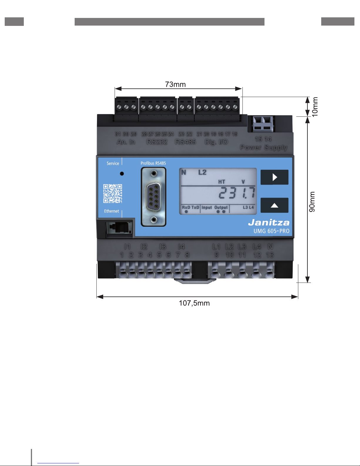
UMG 605-PRO
www.janitza.de
77
19. Dimension diagrams
19. 1 Front view
Fig. Front view of UMG 605-PRO with installation dimensions
Page 83

www.janitza.de
UMG 605-PRO
78
19. 2 Side view
Fig. Schematic side view of UMG 605-PRO with installation dimensions
Page 84
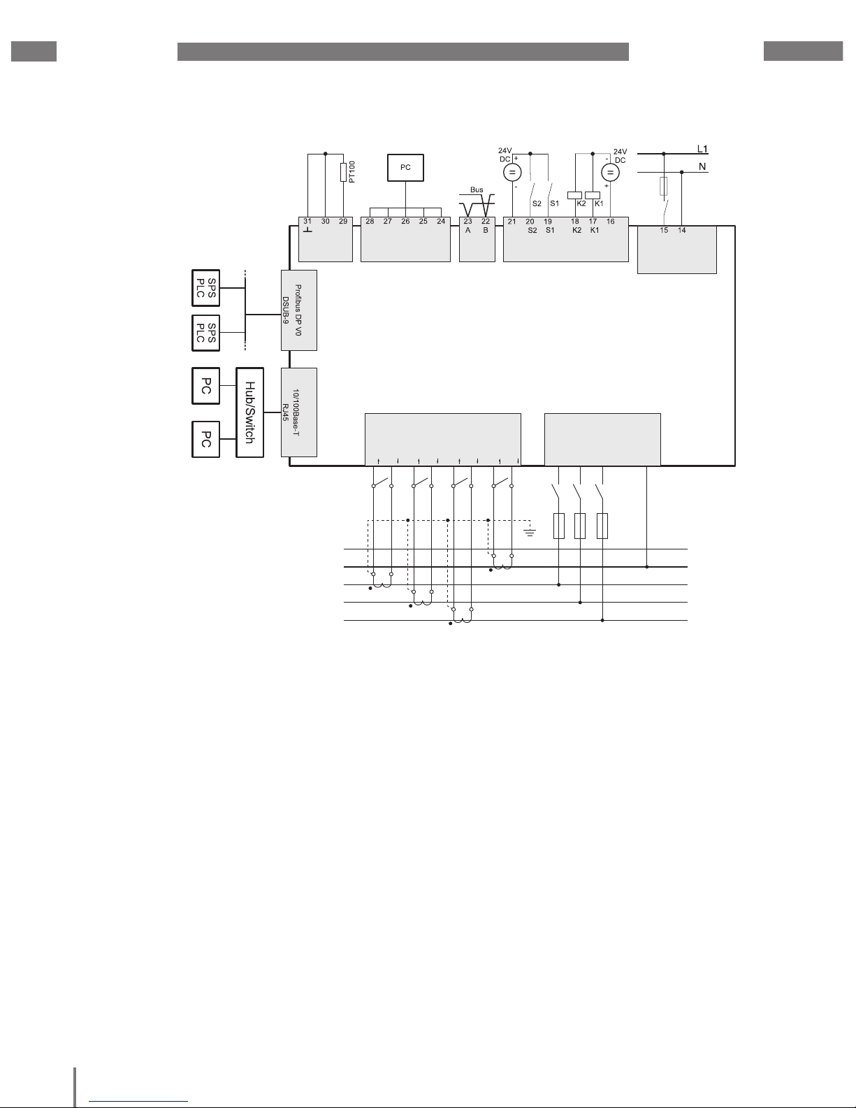
UMG 605-PRO
www.janitza.de
79
20. Connection example
L1
L2
L3
N
PE
S1
S2
S1
S2
S1 S2
S1
S2
Strommessung
Current measurement
I
1
1 2 3 4 5 6 7 8
I2 I3 I4
9 10 11 12
Spannungsmessung
Voltage measurement
L
1 L2 L3 L4
N
13
Versorgungs-
spannung
Auxiliary Supply
Dig. I/ORS485RS232An. In
Option Option
RS485 Ethernet
Verbraucher
Consumer
Power Analyser
UMG 605-PRO
Fig. Connection example for UMG 605-PRO
Page 85

www.janitza.de
UMG 605-PRO
80
Page 86

UMG 605-PRO
www.janitza.de
81
21. Short introduction (setting primary current)
You have three identical current transformers
with a current transformer ratio of 200 A / 5 A.
You want to program the primary current
of 200 A.
To do this, you must enter the value 200
for the primary current in address 000.
The secondary current is factory-set to 5 A
in address 001.
1. Switch to programming mode by
pressing buttons 1 and 2 simultaneously
for approximately one second.
• The symbol for programming mode PRG
appears.
• The contents of address 000 are displayed.
2. Enter the primary current by using button
1 to select the number to be changed and
button 2 to change the selected number.
3. Exit programming mode by pressing
buttons 1 and 2 simultaneously again
for approximately one second.
• The current transformer setting is saved.
• The device returns to display mode.
Address Content
PRG
Address Content
PRG
Fig. UMG 605-PRO display in programming mode
Fig. UMG 605-PRO display in programming mode
Page 87

www.janitza.de
UMG 605-PRO
82
 Loading...