

Page 1

Doc no. 2.054.009.0.p
Power Quality Analyser
UMG 512
Operation manual
and technical data
Part no. 33.03.196 (UL)
Janitza electronics GmbH
Vor dem Polstück 1
D-35633 Lahnau
Support Tel. 0049 6441 9642-22
Fax 0049 6441 9642-30
E-mail: info@janitza.com
Website: http://www.janitza.com
www.janitza.com
Page 2

2
UMG 512
Operation 47
Meaning of the keys 47
Measured value display 48
"Home" measured value display 49
Selecting a measured value display 50
View additional information 51
Deleting min./max. values individually 52
Transients list 53
Event list 54
Configuration 55
Connecting the supply voltage 55
Configuration menu 56
Language 56
Communication 57
Measurement 59
Measuring transducer 60
Transients 64
Events 66
Relevant voltage 68
Nominal frequency 69
Flicker 70
Temperature 70
System 71
Password 72
Resetting 73
Display 76
Extensions 79
Commissioning the unit 81
Connecting the supply voltage 81
Connecting the measured voltage 81
Frequency measurement 82
Table of contents
General information 4
Inspection on receipt 7
Scope of delivery UMG 512 8
Available accessories 8
Product description 9
Proper use 9
UMG 512 features 10
Measuring process 11
Operating concept 11
GridVis network analysis software 11
Connection variants 12
Installation 13
Position of installation 13
Mounting position 13
Front panel section 13
Ethernet 14
Mounting 14
Installation 16
Ground wire connection 16
Supply voltage 16
Voltage measurement 18
Three-phase 3-conductor systems 18
Rated voltages 19
Frequency measurement 27
Current measurement 28
Residual current measurement inputs (RCM) 32
Temperature measurement input 35
RS485 interface 36
Profibus interface 40
Ethernet interface 42
Digital outputs 43
Page 3

3
UMG 512
Direction of the rotating field 82
Applying the measuring-circuit voltage 83
Applying the residual current 85
Checking the power measurement 87
Checking the communication 87
Measurement range exceeded (overload) 88
RS485 interface 89
Profibus 91
Digital in-/outputs 95
Service and maintenance 100
Service 100
Device calibration 100
Calibration intervals 100
Firmware update 101
Battery 101
Technical data 104
Function parameters 111
Dimension diagrams 116
Configuration menu overview 118
Measured value displays overview 119
Connection example 124
Page 4

4
UMG 512
Comments on the manual
We welcome your comments. If anything in this manual
seems unclear, please let us know by sending an e-mail
to: info@janitza.de
General information
Copyright
This manual is subject to the statutory provisions
of copyright law and may not be photocopied, reprinted,
or reproduced - in whole or in part, by mechanical
or electronic means - nor otherwise duplicated
or republished, without the binding written permission
of:
Janitza electronics GmbH, Vor dem Polstück 1,
D 35633 Lahnau, Germany.
Trademarks
All trademarks and the resulting rights are the property
of their respective owners.
Disclaimer
Janitza electronics GmbH accepts no responsibility for
errors or deficiencies within this manual, and makes
no commitment to keep the contents of this functional
description up to date.
Page 5
5
UMG 512
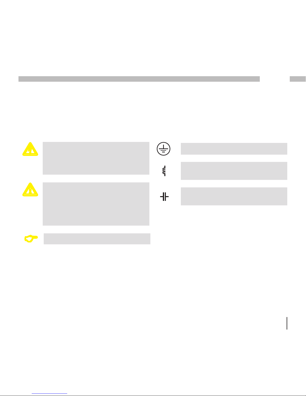
c
Dangerous voltage!
Risk to life or serious injury. Before
commencing work on the system and the
device, they must first be de-energised.
m
Please note!
Please pay attention to the documentation.
This symbol is intended to warn you
of potential dangers, which could occur
during installation, commissioning and use.
C
Note!
Ground wire connection.
Inductive.
The current lags behind the voltage.
Capacitive.
The voltage lags behind the current.
Meaning of symbols
This manual uses the following pictograms:
Page 6
6
UMG 512
Instructions on use
Please read this operation manual as well as all other
publications that must be consulted for working with
this product (in particular, for the installation, operation
or maintenance).
Observe all safety instructions and warnings. Failure
to comply with the instructions can result in personal
injuries and/or damage to the product.
Any unauthorised changes or use of this device, which
go beyond the mechanical, electrical or otherwise stated
operating limitations, can result in bodily injury or/and
damage to the product.
Any such unauthorised change constitutes "misuse"
and/or "negligence" according to the warranty for
the product and thus excludes the warranty for covering
possible damage resulting from this.
This device must only be operated and repaired
by specialised personnel.
Specialised personnel are persons, that based on their
respective training and experience, are qualified
to recognise risks and prevent potential dangers
that can be caused by the operation or maintenance
of the device.
c
If the device is not operated according
to the operation manual, protection
is no longer ensured and hazards can
be presented by the device.
m
Single core conductor must be provided
with sleeves.
m
Only pluggable screw terminals with
the same number of poles and the same
type of construction are permitted
to be connected together.
Additional legal and safety regulations required for
the respective application are to be followed during
the use of the device.
Page 7

7
UMG 512
Concerning this operation manual
This operation manual is part of the product.
• Read the operation manual before using the device.
• Keep the operation manual instructions throughout
the entire service life of the product and have them
readily available for reference.
• Pass the operation manual on to each subsequent
owner or user of the product.
Inspection on receipt
The prerequisites of faultless, safe operation
of this device are proper transport and proper storage,
set-up and installation, as well as careful operation and
maintenance. If it can be assumed that risk-free operation
is no longer possible, the device must be immediately
put out of operation and secured against being put back
into operation again.
Packing and unpacking must be carried out with
customary care without the use of force and only using
suitable tools. The devices should be visually checked
for flawless mechanical condition.
It can be assumed that risk-free operation is no longer
possible if the device, for example,
• has visible damage
• no longer works despite the mains power supply
being intact
• has been exposed to prolonged adverse conditions
(e.g. storage outside the permissible climate
limits without being adapted to the room climate,
condensation, etc.) or rough handling during
transportation (e.g. falling from a height, even if there
is no visible external damage, etc.)
• please check the delivered items for completeness
before you start installing the device.
C
All screw-type terminals included
in the scope of delivery are attached
to the device.
C
All supplied options and versions are
described on the delivery note.
Page 8

8
UMG 512
Scope of delivery UMG 512
Number Part no. Name
1 52.17.xxx
1)
UMG 512
1 33.03.196 Operation manual
1 51.00.116 CD with following content
- GridVis programming software
- GridVis functional description
- UMG 512, GSD file "JAN0EDC.GSD"
1 10.01.855 Screw-type terminal, pluggable, 2-pole (auxilliary power)
1 10.01.847 Screw-type terminal, pluggable, 5-pole (voltage measurement 1-4)
1 10.01.853 Screw-type terminal, pluggable, 8-pole (current measurement 1-4)
1 10.01.873 Screw-type terminal, pluggable, 6-pole (digital inputs/outputs)
1 10.01.888 Screw-type terminal, pluggable, 7-pole (RCM, thermistor input)
1 10.01.859 Screw-type terminal, pluggable, 3-pole (RS 485)
1 08.01.505 Patch cable 2 m, twisted, grey (connection UMG PC/switch)
1 52.19.301 Mounting clips
Available accessories
Part no. Name
21.01.102 Lithium battery CR2450, 3V (approval according to i.a.w. UL 1642)
13.10.539 Profibus connector, 9-pole, D-SUB
13.10.543 Profibus connector, 9-pole, D-SUB, angled
29.01.903 Seal, 144 x 144
1)
For the item number, see delivery note
Page 9

9
UMG 512
Product description
Proper use
The UMG 512 is intended for the measurement
of voltage quality according to EN61000-4-30 in building
installations, on distribution units, circuit breakers
and busbar trunking systems.
Measured voltages and measured currents must derive
from the same network.
The UMG 512 is suitable for integration into fixed and
weatherproof switch panels in indoor areas. Conductive
switch panels must be earthed.
The UMG 512 can be used in 2, 3 and 4-conductor
networks and in TN and TT networks.
The current measurement inputs 1–4 of the UMG 512
are connected via external ../1A or ../5A current
transformers.
Measurements in medium and high-voltage networks are
always performed via current and voltage transformers.
The measurement results can be displayed and read
out and further processed via the interfaces (Ethernet,
Modbus, Profibus).
The UMG 512 can be used in industrial and domestic
settings.
By continuously monitoring the residual currents
(RCM) of an electrical system via the inputs I5 and I6,
warning pulses can be triggered if a response threshold
is exceeded. Using these, the system operator can
be alarmed before a protective equipment reacts.
The UMG 512 does not provide protection against
electric shock!
The residual current monitoring is performed via
the current measurement inputs I5 and I6 via an
external residual current transformer with a rated current
of 30 mA.
m
Residual current monitoring monitors
residual currents via external current
transformers and can trigger a warning
impulse when a response threshold
is exceeded. The device is thus not an
independent protective device!
Page 10

10
UMG 512
UMG 512 features
General information
• Front panel integration device with dimensions
144 x 144 mm
• Connection via pluggable screw terminals
• Colour graphic display 320x240, 256 colours
• Operation via 6 buttons
• 4 Voltage and 4 current measurement inputs
• 2 Residual current inputs with failure monitoring
• 1 Temperature measurement input
• 2 digital outputs and 2 digital inputs
• 16-bit A/D converter, memory 256 Mbyte Flash,
SDRAM 32 Mbyte
• RS485 interface
(Modbus RTU, slave, up to 115 kbps)
• Profibus DP/V0
• Ethernet (web server, e-mail)
• Capturing more than 2000 measured values
• Clock and battery (with battery monitoring function)
• Working temperature range -10°C .. +55°C
Measurement
• Measurement in TN and TT networks
• Continuous sampling of the voltage and
current measurement inputs at 25.6 kHz
• Frequency range of the fundamental oscillation
15Hz .. 440Hz
• Acquisition of transients >39 µs and storage of up
to approx. 330,000 sampling points
• Metering range current 0.001 to 7Arms.
• True RMS (TRMS)
• Continuous sampling of the voltage
and current measurement inputs
• Continuous monitoring of residual currents
with failure monitoring
• Temperature measurement
• Measurement of the power quality in accordance
with DIN EN61000-4-30, Class A
• Flicker measurement in accordance with DIN
EN61000-4-15:2011, Class F1
• Working measurement, measurement uncertainty
in accordance to DIN EN50470-3:
- Class C for ../5A converter,
- Class B for ../1A converter,
• Measurement of the harmonics 1st to 63rd in
accordance with DIN EN61000-4-7 class 1, for
- Ull, Uln, I, P (cons./del.) and
- Q (ind./cap.),
• Measurement of the interharmonics 1st to 63rd
for (Uln, Ull, I) in accordance with DIN EN61000-4-7
cl.1
• Analysis and evaluation in accordance with
DIN EN50160 with the GridVis programming
software included in the scope of delivery
• Programming separate applications in Jasic
Page 11

11
UMG 512
Measuring process
The UMG 512 measures continuously and calculates
all effective values over a 200 ms interval. The device
measures the real effective value (TRMS) of the voltages
and currents connected to the measurement inputs.
Operating concept
You can program and call up the measured values via
many routes using the UMG 512.
• Directly on the device via 6 buttons and the display
• Using the GridVis programming software.
• Using the device homepage
• Using the Modbus protocol.
You can modify and call up the data using the
Modbus address list. The list can be called up via
the device's home page and can be found on the
enclosed CD.
This operation manual only describes how to operate the
UMG 512 using the six buttons.
The GridVis programming software has its own "online
help" system.
GridVis network analysis software
The UMG 512 can be programmed and read out
using the GridVis network analysis software included
in the scope of the delivery. For this, a PC must be
connected to the UMG 512 via a serial interface (RS485/
Ethernet).
GridVis features
• Programming the UMG 512
• Configuring recordings
• Analysing the read out data according
to EN 61000-2-4.
• Reading out recordings
• Saving data to a database
• Graphical representation of measured values
• Programming customer-specific applications
Page 12

12
UMG 512
Connection variants
Connection of a UMG 512 to a PC via an interface converter:
Connection of a UMG 96RM via a UMG 512 as a gateway
UMG 512
Direct connection of a UMG 512 to a PC via Ethernet.
Connection of a UMG 512 to a PC via Ethernet.
UMG 96RM
UMG 96RM
UMG 512
(twisted patch cable)
UMG 512
(twisted patch cable)
UMG 512
Switch
Page 13

13
UMG 512
Installation
Position of installation
The UMG 512 is suitable for integration into fixed and
weatherproof switch panels in indoor areas. Conductive
switch panels must be earthed.
Mounting position
To ensure adequate ventilation, the UMG 512 must
be installed vertically. There should be separation
above and below of at least 50mm with 20mm space
to the sides.
Front panel section
Cut-out size:
138
+0.8
x 138
+0.8
mm.
m
Failure to meet the minimum clearances
can destroy the UMG 512 at high ambient
temperatures!
Fig. mounting
position UMG 512
(View from rear)
Page 14

14
UMG 512
Ethernet
The Ethernet connection of the UMG 512 is on the bottom
of the housing.
Depending on the bending radius of the Ethernet cable
and connector type, you must install a connection area
below the UMG 512.
The connection area below the UMG 512 should not
be smaller than 50 mm.
Mounting
The UMG 512 is mounted in the switchboard with two
mounting clips that are installed at the top and bottom
of the device.
Ethernet connection
Patch cable
50 mm
Page 15

15
UMG 512
Page 16
16
UMG 512
Installation
Ground wire connection
Use a ring cable lug for connecting the protective
conductor to the UMG 512.
Supply voltage
The UMG 512 needs supply voltage to operate. The type
and amount of the supply voltage required is specified
on the rating plate. The supply voltage is connected
on the rear side of the device via terminal blocks.
Before connecting the supply voltage, ensure that
the voltage and frequency correspond to the details
on the rating plate!
The supply voltage must be connected through a UL/IEC
approved fuse.
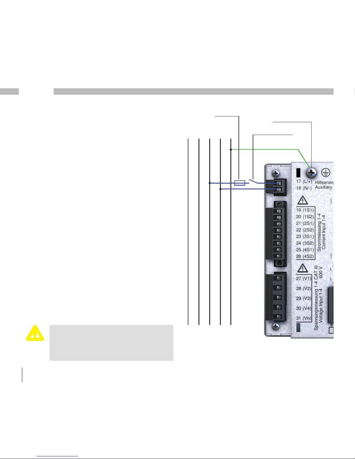
c
Caution: Risk to life!
The ground wire connection on the device
must be connected with the system
earthing.
Fig. connection example of the supply voltage
to a UMG 512.
Circuit breaker
Fuse
L1 N PEL3L2
Protective conductor
Connection point of the
protective conductor
Page 17
17
UMG 512
m
• If installed in a building, a disconnector
or circuit breaker must be provided for
the supply voltage.
• The disconnector must be installed
near the device and easily accessible
to the user.
• The switch must be marked as the circuit
breaker for this device.
• Voltages which are over the permitted
voltage range can destroy the device.
c
Please note!
The inputs for the supply voltage are
hazardous if touched!
c
Please note!
Make sure to observe the specifications
for the supply voltage that are provided
on the rating plate of the UMG 512.
Page 18
18
UMG 512
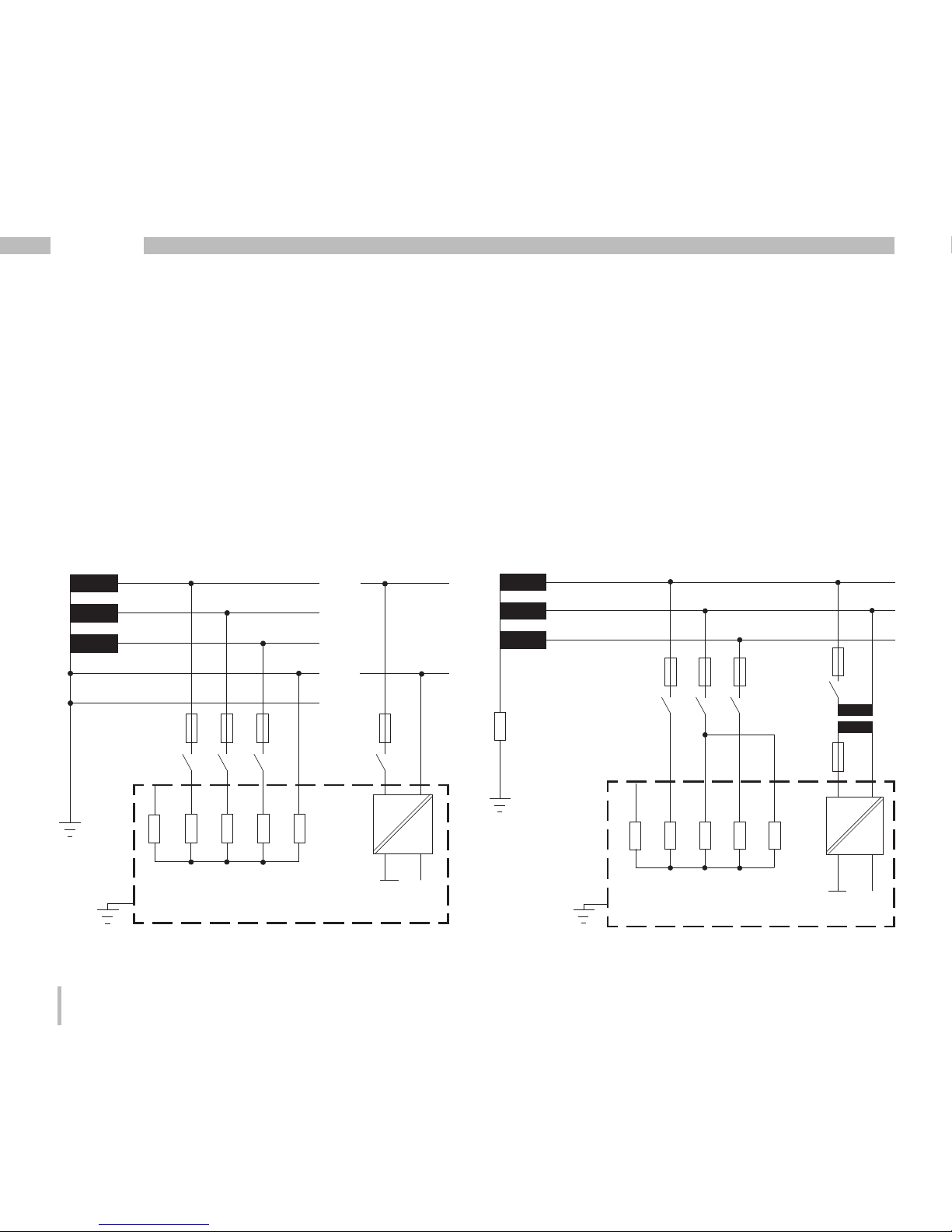
Voltage measurement
Three-phase 4-conductor systems
The UMG 512 can be used in three-phase 4-conductor
systems (TN, TT networks) with an earthed neutral
conductor. The bodies of the electrical system are
earthed.
The voltage measurement in the UMG 512 is designed
for the overvoltage category 600V CAT III (measurement
voltage surge 6kV).
Three-phase 3-conductor systems
The UMG 512 is only suitable to a limited extent for use
in IT networks, since the measured voltage relative to the
housing potential is measured and the input impedance
of the device creates residual current against the earth.
The residual current can trigger the insulation monitoring
in IT networks.
The connection variants with voltage transformers are
suitable for unlimited use in IT networks.
PE
347V/600V 50/60Hz
L2
L3
N
L1
N
L1
240V
50/60Hz
System
earthing
DC
AC/DC
Auxilliary power
Voltage measurement
4M
4M
4M
4M
V1
V3V2 Vref
4M
V4
UMG 512
Fig. Schematic diagram, UMG 512 in a TN network.
Fig. Schematic diagram, UMG 512 in an IT network without N.
600V 50/60Hz
DC
AC/DC
L2
L3
Auxilliary power
Voltage measurement
4M
4M
4M
4M
V1
V3V2
4M
V4
System
earthing
Impedance
L1
UMG 512
Vref
Page 19

19
UMG 512
Maximum system rated
voltage
Rated voltages
Lists of networks and their nominal network voltages
in which the UMG 512 can be used.
Three-phase 4-conductor systems with earthed
neutral conductor.
Maximum system rated
voltage according to UL
U
L-N
/ U
L-L
66V / 115V
120V / 208V
127V / 220V
220V / 380V
230V / 400V
240V / 415V
260V / 440V
277V / 480V
347V / 600V
400V / 690V
417V / 720V
Maximum system rated
voltage
Fig. Table for network rated voltages i.a.w. EN606641:2003 suitable for the voltage measurement inputs.
U
L-L
66V
115V
120V
127V
200V
220V
230V
240V
260V
277V
347V
380V
400V
415V
440V
480V
500V
577V
600V
Three-phase 3-conductor systems, ungrounded.
Fig. Table for network rated voltages i.a.w. EN606641:2003 suitable for the voltage measurement inputs.
Page 20
20
UMG 512
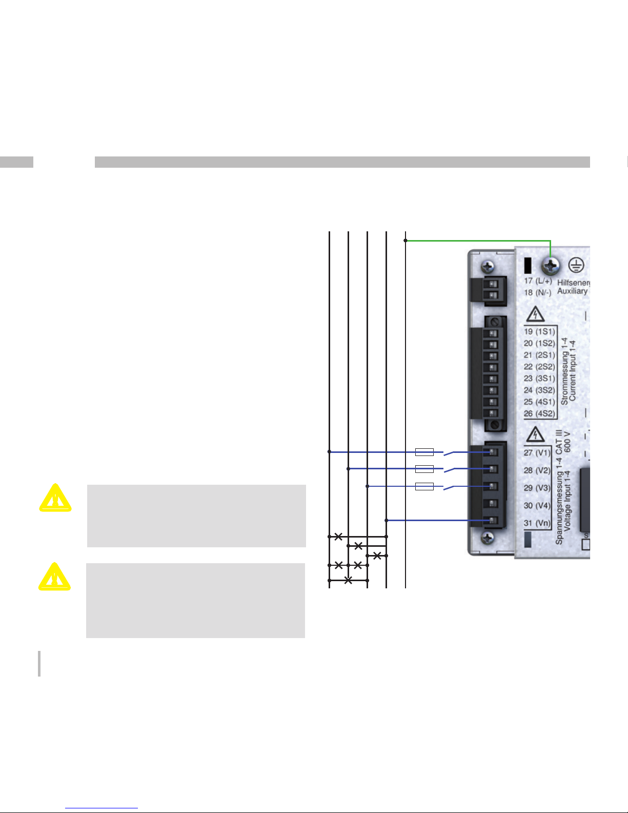
Voltage measurement inputs
The UMG 512 has four voltage measurement inputs (V1,
V2, V3, V4).
Voltage swell
The voltage measurement inputs are suitable for
measurements in networks where overvoltages
of overvoltage category 600V CATIII can occur.
For measurement with the supporting
measurement (V4), a voltage must be
connected to the baseline measurement
for frequency determination.
m
If the baseline measurement (inputs
V1-V3) is connected to a three-phase
3-conductor network, the supporting
measurement (input V4) can no longer be
used as a measurement input.
m
L1 N PEL3L2
Fig. Example connection for measuring voltage.
Page 21
21
UMG 512
When connecting the voltage to be measured,
the following must be observed:
• A suitable circuit breaker must be fitted to
disconnect and de-energise the UMG 512.
• The circuit breaker must be placed in the vicinity
of the UMG 512, be marked for the user and easily
accessible.
• Use a UL/IEC approved circuit breaker for the
overcurrent protection and disconnector.
• The overcurrent protection must have a rated
value, which is suitable for the short circuit current
at the connection point.
• Measured voltages and measured currents must
derive from the same network.
c
Please note!
Voltages that exceed the allow nominal
network voltages must be connected via
a voltage transformer.
c
Please note!
The UMG 512 is not suitable for measuring
DC voltages.
c
Please note!
The voltage measurement inputs on
the UMG 512 are dangerous if touched!
c
Please note!
The voltage measurement inputs may not
be used for voltage measurement in SELV
circuits (safe extra low voltage).
Page 22
22
UMG 512
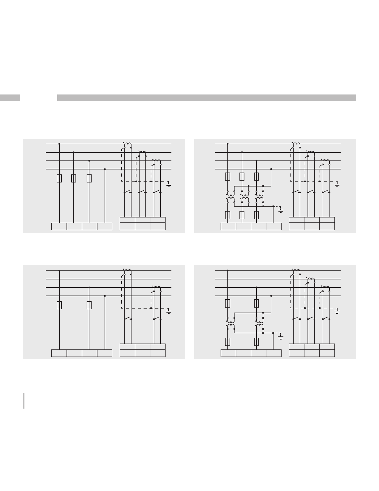
Fig. Measurement via 3 voltage transformers in a threephase 4-conductor network with asymmetric loading.
Baseline measurement, digital inputs 1-3
Fig. Measurement in a three-phase 4-conductor network
with asymmetric loading.
Fig. Measurement via 2 voltage transformers in a threephase 4-conductor network with asymmetric loading.
Fig. Measurement in a three-phase 4-conductor network
with symmetric loading.
L1
L2
L3
N
L1 L2 L3 N
4w 3m
I1 I2 I3
S1 S2 S1 S2 S1 S2
L1
L2
L3
N
L
1 L2 L3 N
4w 3m
hv
I
1 I2 I3
S1 S2 S1 S2 S1 S2
L1
L2
L3
N
4w 2i
L1
L2
L3
N
L1 L2 L3 N
4w 3m
hv
I1 I2 I3
S1 S2 S1 S2 S1 S2
L1
L2
L3
N
L
1 L2 L3 N
4w 2i
I1 I2 I3
S1 S2 S1 S2 S1 S2
L1
L2
L3
N
L
1 L2 L3 N
4w 3m
I1 I2 I3
S1 S2 S1 S2 S1 S2
L1
L2
L3
N
L
1 L2 L3 N
4w 3m
hv
I
1 I2 I3
S1 S2 S1 S2 S1 S2
L1
L2
L3
N
4w 2i
L1
L2
L3
N
L1 L2 L3 N
4w 2m
I1 I2 I3
S1 S2 S1 S2 S1 S2
L1
L2
L3
N
L
1 L2 L3 N
4w 2u
hv
I
1 I2 I3
S1 S2 S1 S2 S1 S2
L1
L2
L3
N
4w 2u
L1
L2
L3
N
L
1 L2 L3 N
4w 3m
hv
I
1 I2 I3
S1 S2 S1 S2 S1 S2
L1
L2
L3
N
L
1 L2 L3 N
4w 2i
I1 I2 I3
S1 S2 S1 S2 S1 S2
L1
L2
L3
N
L1 L2 L3 N
4w 2u
hv
I1 I2 I3
S1 S2 S1 S2 S1 S2
L1
L2
L3
N
L
1 L2 L3 N
4w 2u
I1 I2 I3
S1 S2 S1 S2 S1 S2
Page 23

23
UMG 512
Fig. Measurement in a three-phase 4-conductor
network with asymmetric loading.
Fig. Measurement via 2 voltage transformers in a threephase 3-conductor network with symmetric loading.
L1
L2
L3
N
L1 L2 L3 N
4w 2i
I1 I2 I3
S1 S2 S1 S2 S1 S2
L1
L2
L3
N
L
1 L2 L3 N
4w 2i
I1 I2 I3
S1 S2 S1 S2 S1 S2
L1
L2
L3
N
L1 L2 L3 N
4w 2u
I1 I2 I3
S1 S2 S1 S2 S1 S2
Page 24

24
UMG 512
Fig. Measurement in a three-phase 3-conductor network
with asymmetric loading.
Fig. Measurement in a three-phase 3-conductor network
with asymmetric loading.
Fig. Measurement in a three-phase 3-conductor network
with asymmetric loading.
Fig. Measurement in a three-phase 3-conductor network
with asymmetric loading.
L1
L2
L3
L1 L2 L3 N
3w 3m
I1 I2 I3
S1 S2 S1 S2 S1 S2
L1
L2
L3
L
1 L2 L3 N
3w 2i
I1 I2 I3
S1 S2 S1 S2 S1 S2
L1
L2
L3
3w 2m
L1
L2
L3
L1 L2 L3 N
3w 2i
I1 I2 I3
S1 S2 S1 S2 S1 S2
L1
L2
L3
L
1 L2 L3 N
3w 2m
I1 I2 I3
S1 S2 S1 S2 S1 S2
L1
L2
L3
3w 2m
hv
L1
N
2w 1m
L1
L2
L3
L
1 L2 L3 N
3w 3m
I1 I2 I3
S1 S2 S1 S2 S1 S2
L1
L2
L3
L
1 L2 L3 N
3w 2i
I1 I2 I3
S1 S2 S1 S2 S1 S2
L1
L2
L3
3w 2m
L1
L2
L3
L1 L2 L3 N
3w 2u
I1 I2 I3
S1 S2 S1 S2 S1 S2
L1
L2
L3
L
1 L2 L3 N
3w 2u
hv
I
1 I2 I3
S1 S2 S1 S2 S1 S2
L1
N
L
1 L2 L3 N
2w 1m
I1 I2 I3
S1 S2 S1 S2 S1 S2
L1
L2
L3
L
1 L2 L3 N
3w 2i
I1 I2 I3
S1 S2 S1 S2 S1 S2
L1
L2
L3
L
1 L2 L3 N
3w 2m
I1 I2 I3
S1 S2 S1 S2 S1 S2
L1
L2
L3
3w 2m
hv
L1
L2
L3
L1 L2 L3 N
3w 2u
hv
I1 I2 I3
S1 S2 S1 S2 S1 S2
2w 2m
L1
L2
Page 25

25
UMG 512
Fig. Measurement in single-phase 3-conductor network.
I3 and U3 are not calculated and set to zero.
Fig. Measurement in a three-phase 3-conductor network
with asymmetric loading.
Fig. Measurement in a three-phase 3-conductor network
with asymmetric loading.
Fig. Measurement of one phase in a three-phase
4-conductor network.
L1
L2
L3
L1 L2 L3 N
3w 2m
I1 I2 I3
S1 S2 S1 S2 S1 S2
L1
L2
L3
L
1 L2 L3 N
3w 2m
hv
I
1 I2 I3
S1 S2 S1 S2 S1 S2
L1
L2
L3
L1 L2 L3 N
3w 2m
hv
I1 I2 I3
S1 S2 S1 S2 S1 S2
L1
N
L1 L2 L3 N
2w 1m
I1 I2 I3
S1 S2 S1 S2 S1 S2
L1
L2
L3
L
1 L2 L3 N
3w 2m
I1 I2 I3
S1 S2 S1 S2 S1 S2
L1
L2
L3
L
1 L2 L3 N
3w 2m
hv
I
1 I2 I3
S1 S2 S1 S2 S1 S2
L1 L2 L3 N
2w 2m
I1 I2 I3
S1 S2 S1 S2 S1 S2
L1
L2
L1
L2
L3
L
1 L2 L3 N
3w 2m
hv
I
1 I2 I3
S1 S2 S1 S2 S1 S2
L1 L2 L3 N
2w 2m
I1 I2 I3
S1 S2 S1 S2 S1 S2
L1
L2
Page 26

26
UMG 512
Supporting measurement, input V4
Fig. Measurement in a three-phase 4-conductor
network with symmetric loading.
Fig. Measurement in a three-phase 3-conductor
network with symmetric loading.
Fig. Measurement of the voltage between N and PE.
Measurement of the current in the neutral conductor.
L1
L2
L3
N
L4 N
4w 1m
I4
S1 S2
L1
L2
L3
L
4 N
3w 1m
I4
S1 S2
L1
L2
L3
L4 N
3w 1m
I4
S1 S2
L1
L2
L3
N
L
4 N
4w 1m
I4
S1 S2
L1
L2
L3
L
4 N
3w 1m
I4
S1 S2
N
L4 N
2w 1n
I4
S1 S2
PE
m
If the baseline measurement (inputs
V1-V3) is connected to a three-phase
3-conductor network, the supporting
measurement (input V4) can no longer
be used as a measurement input.
m
For measurement with the supporting
measurement (V4), a voltage must
be connected to the baseline measurement
for frequency determination.
Page 27

27
UMG 512
Frequency measurement
The UMG 512 is suitable for measurements in networks
in which the fundamental oscillation of the voltage
is in the range 15Hz to 440Hz.
To automatically determine (wide range) the mains
frequency, a voltage L1-N of greater than 10Veff must
be applied to voltage measurement input V1.
The mains frequency is only measured
on the measurement inputs of the baseline measurement
(V1,V2,V3).
Measured voltages and measured currents
must derive from the same network.
m
Page 28

28
UMG 512
Current measurement
The UMG 512 is intended for the connection of current
transformers with secondary currents of ../1A and ../5A.
The factory default for the current transformer ratio
is 5/5A and must be adapted to the current transformer
employed if necessary.
Only AC currents can be measured - DC currents cannot.
Any of the current measurement inputs can be loaded
with 120A for 1 second.
Fig. Current measurement (I1-I3) via current
transformers (connection example)
S1
S2
L1 N PEL3L2
S1
S2
S1
S2
S1
S2
Load
c
Please note!
The measurement lines must be suitable
for an operating temperature of at least
80°C!
m
The attached screw-type terminal must be
fixed using the two screws on the device!
m
Please note!
The UMG 512 is not suitable for measuring
DC voltages.
c
Attention!
The current transformer must have basic
insulation per IEC 61010 1:2010, as a
minimum, for the nominal voltage of the
circuit to be measured.
Page 29

29
UMG 512
c
Earthing of current transformers!
A secondary connection for each current
transformer must be connected to ground.
Current direction
The current direction can be individually corrected via
the existing serial interfaces or on the device for each
phase.
If incorrectly connected, a subsequent re-connection of
the current transformer is not required.
c
Open-circuit current transformers!
High voltage spikes that are dangerous
to touch can occur on current transformers
that are driven with open-circuit secondary
windings!
With "safe open-circuit current
transformers" the winding insulation
is rated such that the current transformer
can be driven open. However, even these
current transformers are dangerous to
touch when they are driven open-circuit.
c
Current transformer connections!
The secondary connection of the current
transformer must be short circuited on this
before the current feed to the UMG 512
is disconnected!
If a test switch, which automatically shortcircuits the secondary wires of the current
transformer, is available then it is sufficient
to set this to the "Test" position insofar
as the short-circuiting device has been
checked beforehand.
c
Please note!
Residual current monitoring is performed
using the terminals I5 and I6. There is no
directional sensitivity of the residual
currents of the network or load sides (not
directionally sensitive).
Page 30

30
UMG 512
Total current measurement
If the current measurement is done via two current
transformers, the overall transformation ratio
of the current transformers must be programmed into
the UMG 512.
Fig. Example, current measurement via a total
current transformer
UMG
S2
I
S
1
P1
P2
Einspeisung 1
Supply 1
Einspeisung 2
Supply 2
1P1
1P2
(K)
(L)
(k)
(l)
1S
2
1S1
1S1 1S2 2S1 2S2
2S1
2S2
(k)
(l)
(K)
(L)
2P
1
2P2
Verbraucher A
Consumer A
Verbraucher B
Consumer B
Example:
The current is measured via two current transformers.
Both current transformers have a transformation ratio
of 1000/5A. The summation measurement is performed
using a total current transformer 5+5/5A.
The UMG 512 must then be setup as follows:
Primary current: 1000A + 1000A = 2000A
Secondary current: 5A
Page 31
31
UMG 512
Ammeter
If you wish to measure the current not just using
the UMG 512, rather also with an ammeter, the ammeter
must be connected to the UMG 512 in series.
UMG
S2
I
S
1
Einspeisung
Supply
Verbraucher
Consumer
A
(k)S
1 S2(l)
P
2(L)(K)P1
Page 32
32
UMG 512
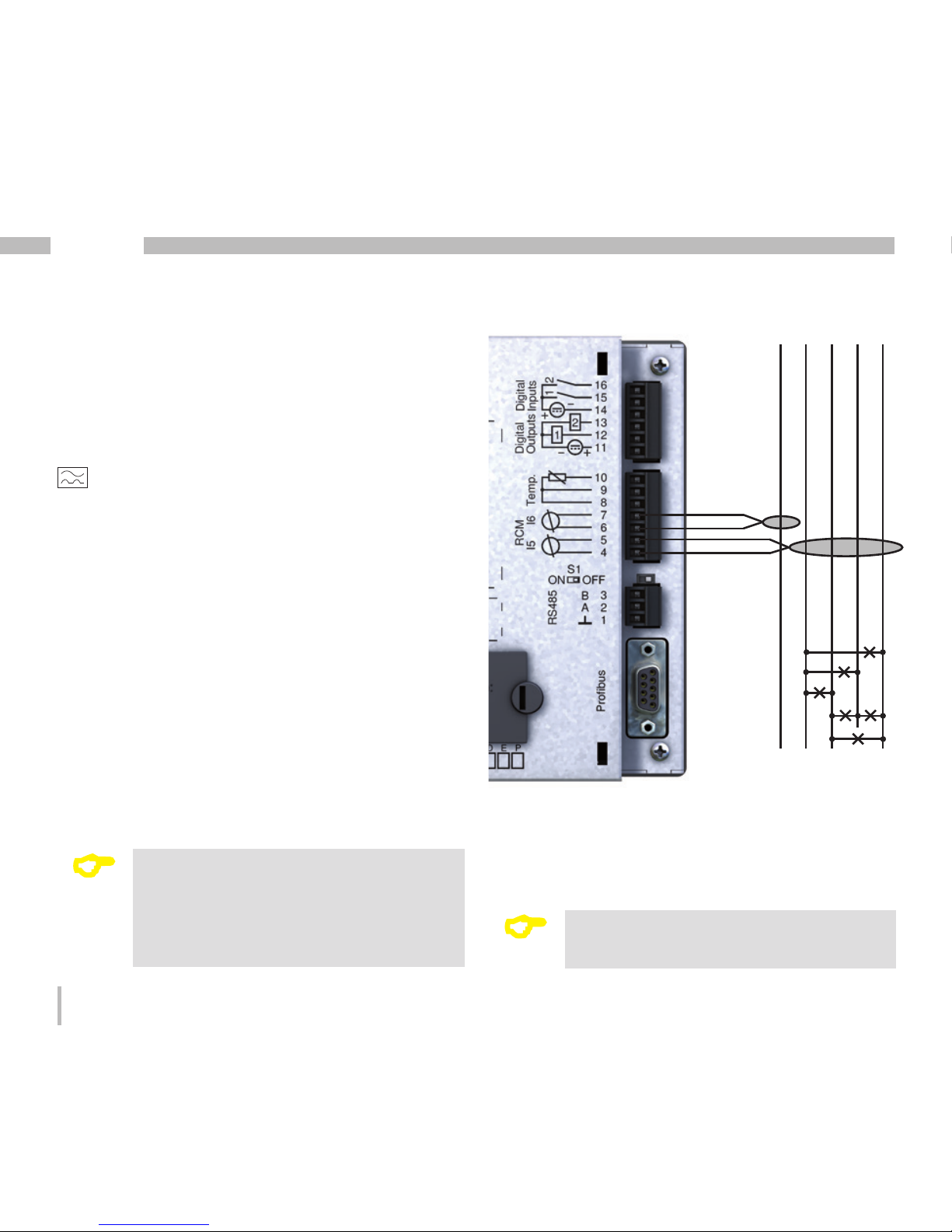
Residual current measurement inputs (RCM)
The UMG 512 is suitable for use as a residual current
monitoring device (RCM) as well as for monitoring AC,
pulsing DC, and DC.
The UMG 512 can measure type A residual currents
in accordance with IEC/TR 60755 (2008-01)
.
The connection of suitable external residual current
transformers with a rated current of 30 mA is performed
via the residual current transformer inputs I5 (terminals
4/5) and I6 (terminals 6/7).
C
Residual current transformer ratio
The GridVis software included in the scope
of the delivery can be used to individually
program the residual current transformer
inputs' transformer ratios.
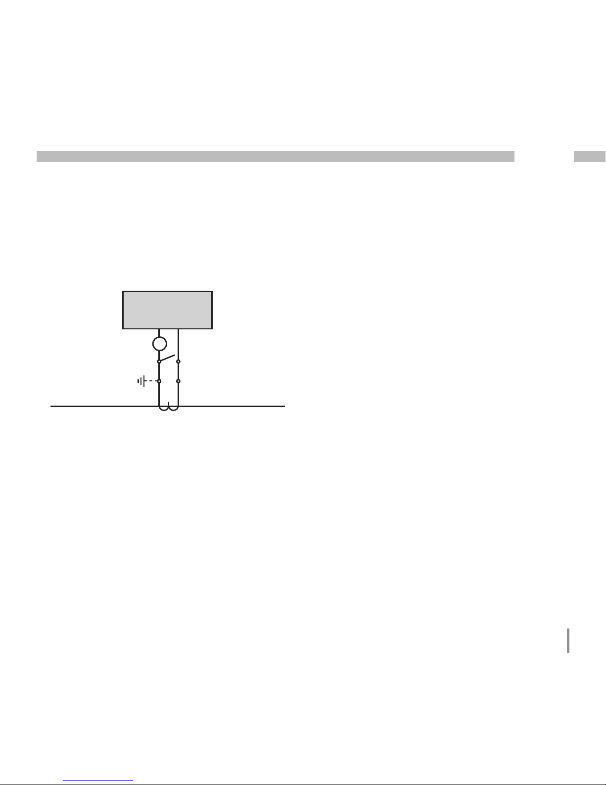
Fig. Connection example of residual current monitoring
via current transformers
L2 L3N L1
Load
PE
C
It is not necessary to configure a connection
schematic for measurement inputs I5 and I6.
Page 33

33
UMG 512
c
Please note!
Operating equipment connected to the
analogue inputs (residual current and temperature measurement) must feature reinforced or double insulation to the mains
supply circuits!
Example - temperature sensor:
A temperature sensor in close proximity
to non-isolated mains cables should measure
within a 300V CAT III network.
Remedy:
The temperature sensor must be equipped
with reinforced or double insulation for 300V
CAT III.
Example - residual current transformer:
A residual current transformer should measure
on isolated mains cables within a 300V CAT III
network.
Remedy:
The insulation of the mains cables
and the insulation of the residual current
transformer must fulfil the basic insulation
requirements for 300V CAT III.
Failure monitoring
The UMG 512 monitors the ohmic resistance
at the residual current measurement inputs.
If the ohmic resistance is greater than 300 Ohm, there
is a failure (e.g. cable breakage) with the residual current
monitoring.
Page 34
34
UMG 512
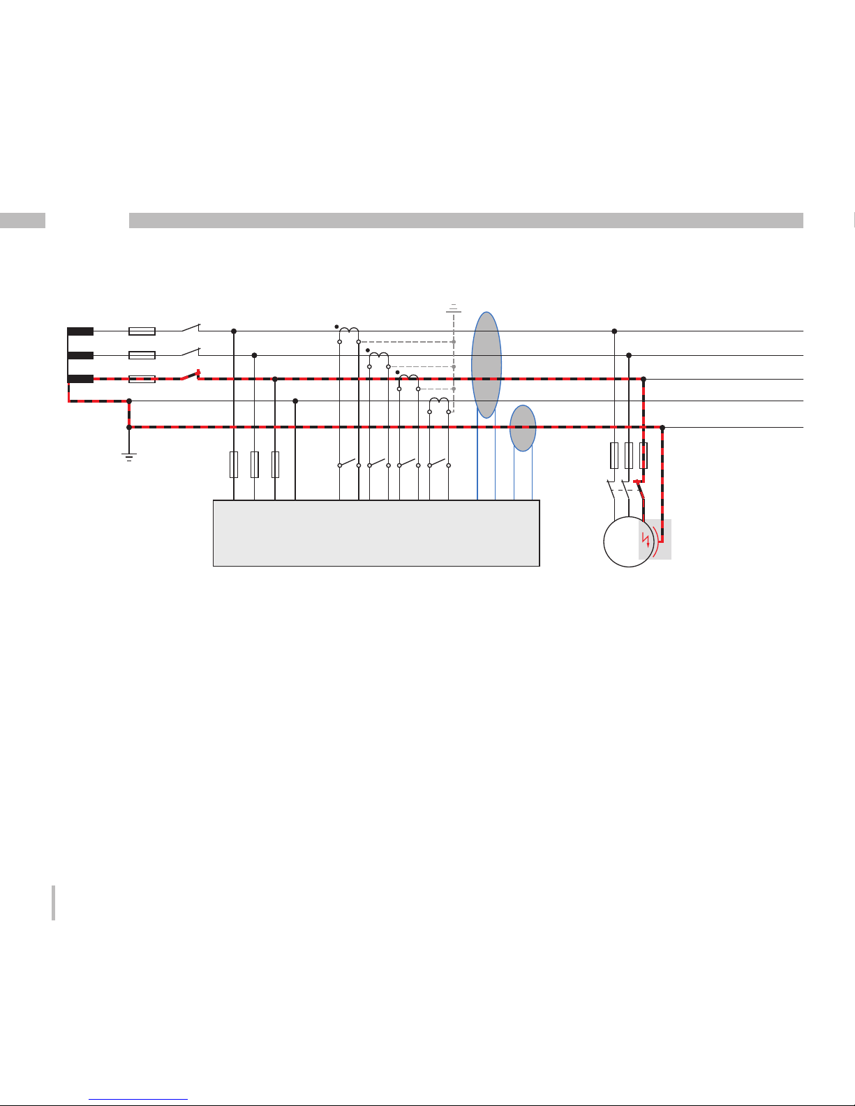
L1 L2 L3 N I1 I2 I3
L1
L2
L3
PEN
N
PE
UMG 512
M
3~
I5
I6
I4
Fig. Example UMG 512 with residual current monitoring via measuring inputs I5/I6.
Residual
current
transformers
Residual current transformer
Page 35
35
UMG 512
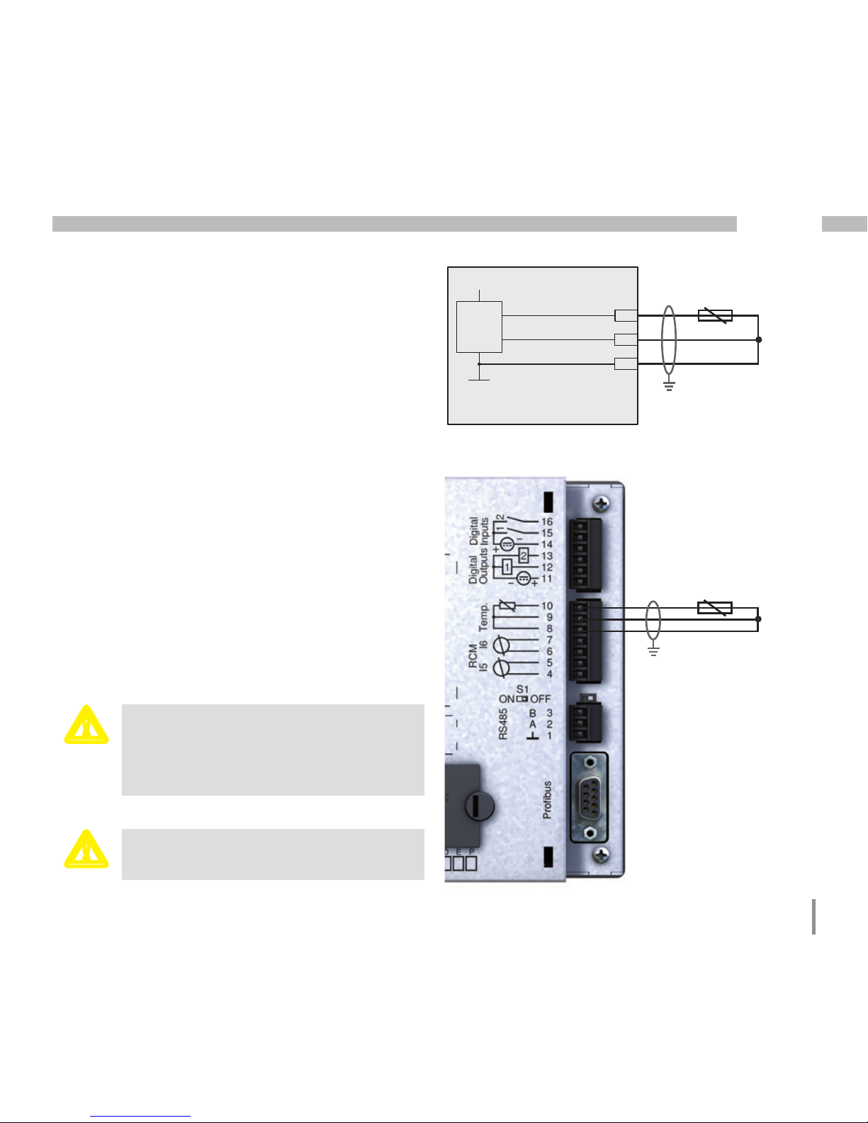
Temperature measurement input
The UMG 512 has one temperature measurement
input. The temperature is measured here via terminals
8 through 10.
Do not exceed the total resistance load (sensor + cable)
of 4kOhm.
PT100
GND
VCC
10
9
8
UMG 512
Fig. Example, temperature
measurement with a Pt100
m
Use a shielded cable to connect the temperature sensor.
PT100
m
Please note!
Temperature and residual current measurement (RCM) are not galvanically separated
from each other.
Page 36

36
UMG 512
RS485 interface
In the UMG 512, the RS485 interface is designed as a
3-pin plug contact, which communicates via the Modbus
RTU protocol.
A B
RS485 Bus
Correct
Incorrect
Termination resistors
The cable is terminated with resistors (120Ohm, 1/4W)
at the beginning and at the end of a segment.
Termination within the device is possible via the S1 DIP
switch of the UMG 512.
Terminal strip in the cabinet.
Device with RS485 interface.
(without termination resistor)
Device with RS485 interface.
(with termination resistor on the device)
Page 37

37
UMG 512
S1
ON
OFF
Fig.: Placement in the middle
of the segment; termination via S1
DIP switch deactivated (OFF)
S1
ON
OFF
Fig.: Placement at the end of
the segment; termination via S1
DIP switch activated (ON)
Screening
Twisted screened cable should be used for connections
via the RS485 interface.
• Earth the screens of all cables that lead to the cabinet
and at the cabinet entry.
• Connect the screens over a generous area and
in a manner that will conduct well, to a low-noise
earth.
• Gather the cables mechanically above the earthing
clamp in order to avoid damage due to cable
movements.
• Use suitable cable glands to feed the cables into
the cabinet, for example, armoured conduit couplings.
Page 38

38
UMG 512
Cable type
The cable used must be suitable for an environmental
temperature of at least 80°C.
Recommended cable types:
Unitronic Li2YCY(TP) 2x2x0.22 (from Lapp Kabel)
Unitronic BUS L2/FIP 1x2x0.64 (from Lapp Kabel)
Maximum cable length
1200m at a baud rate of 38.4k.
Fig. Screening procedure at cabinet entry.
Cable
Strain relief
Screen braid of the cable
Earthing clamp
Noiseless ground
C
CAT cables are not suitable for bus wiring.
Use the recommended cable types for this.
C
If the bus line is laid in the switch cabinet,
the screen must be connected to functional earth (PE).
When laying bus lines in the switch cabinet
it is normally sufficient if the screen of the
bus line is connected at least once to the
functional earth (PE).
If there are more significant sources of interference, such as a frequency converter,
installed in the switch cabinet, the screen
must be connected to the functional earth
(PE) as close as possible to the device.
Page 39
39
UMG 512
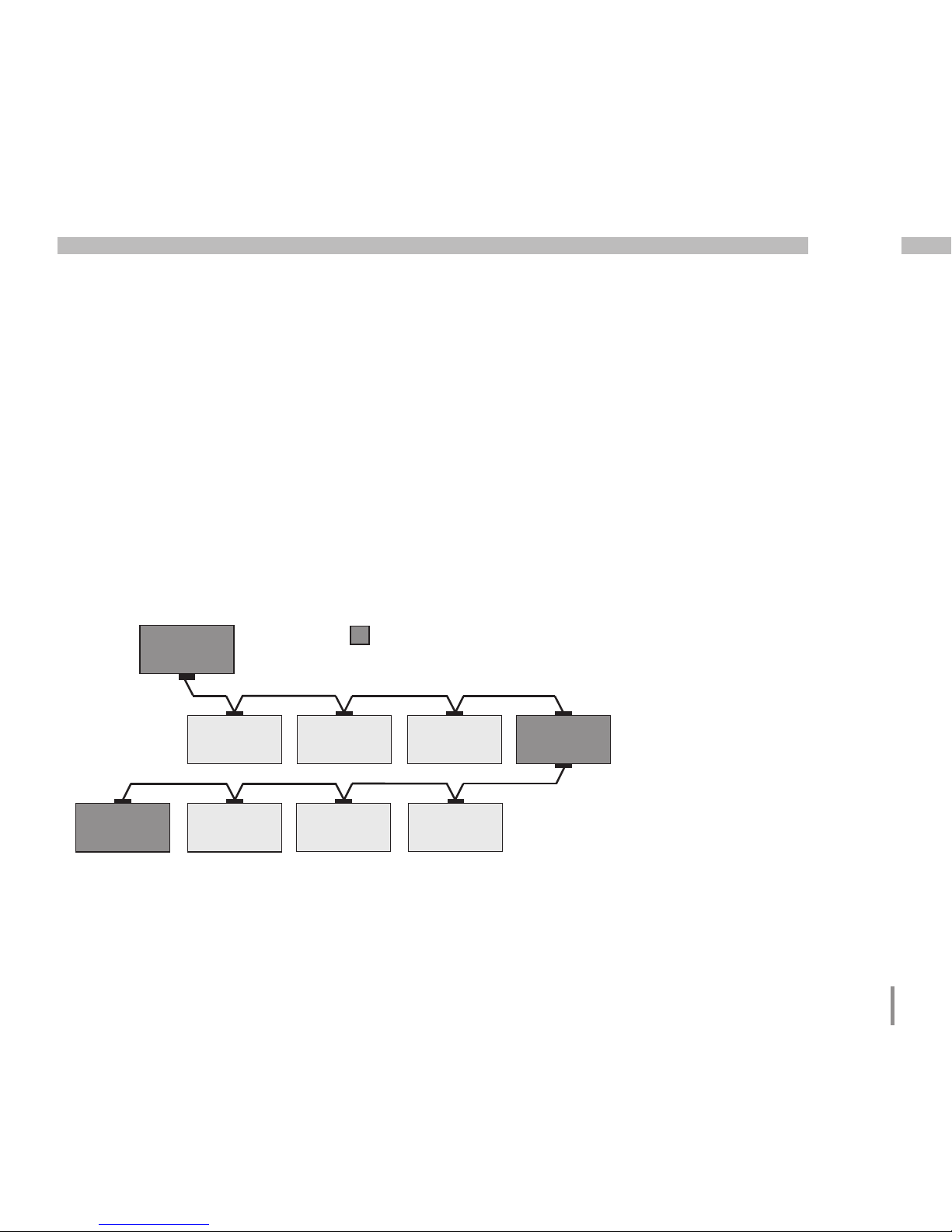
Bus structure
• All devices are connected in a bus structure (line)
and each device has its own address within the bus
(see also Parameter programming).
• Up to 32 subscribers can be connected together
in a single segment.
• The cable is terminated with resistors (bus termination
120Ohm, 1/4W) at the beginning and at the
end of a segment.
• With more than 32 subscribers, repeaters (amplifiers)
must be used to connect the individual segments.
• Devices for which the bus connection is switched
on must be under current.
• It is recommended that the master be placed
at the end of a segment.
• If the master is replaced with a bus connection,
the bus must be switched off.
• Replacing a slave with a bus connection that is either
switched on or de-energised can destabilise the bus.
• Devices that are not connected to the bus can be
replaced without destabilising the bus.
Fig. Bus structure
SlaveSlaveSlave
Slave Slave Slave Repeater
Slave Slave Slave Slave
Master
Speisung notwendig / power supply necessary
Busabschluß eingeschaltet / bus terminator on
T
T
T
T
T
Page 40

40
UMG 512
Profibus interface
This 9-pole D-sub receptacle RS485 interface supports
the Profibus DP V0 slave protocol.
For the simple connection of inbound and outbound
bus wiring, it should be connected to the UMG 512 via a
Profibus connector.
For the connection, we recommend a 9-pole Profibus
connector, e.g. type "SUBCON-Plus-ProfiB/AX/SC"
from Phoenix, item number 2744380. (Janitza item no:
13.10.539)
C
When using the device in a Profibus
system, the device address must be set
using the configuration menu.
D-sub
receptacle for
Profibus
Fig. UMG 512 with D-sub
receptacle for Profibus
(View from rear).
UMG 512
Profibus
Profibus connector (external)
Terminating resistors
Screw-type terminals
Other
profibus
stations
D-Sub,
9 pin,
connector
D-Sub,
9 pin,
socket
Fig. Profibus connector with termination resistors.
Page 41
41
UMG 512
Connection of the bus wiring
The inbound bus wiring is connected to terminals 1A
and 1B of the Profibus connector. The continuing bus
wiring for the next device in line should be connected
to terminals 2A and 2B.
If there are no subsequent devices in the line, then
the bus wiring must be terminated with a resistor (switch
to ON).
With the switch set to ON, terminals 2A and 2B are
switched off for further continuing bus wiring.
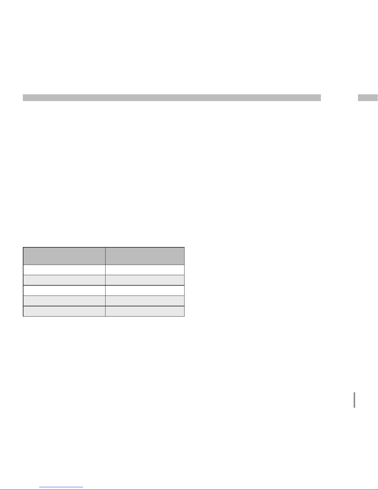
Transfer speeds
in Kbit/s
Max.
segment length
9.6, 19.2, 45.45, 93.75 1200m
187.5 1000m
500 400m
1500 200m
3000, 6000, 12000 100m
Table Segment lengths per Profibus specification.
Page 42

42
UMG 512
Ethernet interface
The Ethernet network settings should be specified by
the network administrator and set on the UMG 512
accordingly.
If the network settings are not known, the UMG 512 may
not be integrated into the network through the patch
cable.
m
Please note!
Connection of the UMG 512 to the Ethernet
may only be carried out after consulting
the network administrator!
PC / switch
m
Please note!
The UMG 512 is factory-set for the dynamic
IP address assignment (DHCP mode).
Settings can be changed as described in
"TCP/IP Configuration" or, for example,
via an appropriate Ethernet connection by
means of GridVis software.
Ethernet connection
Patch cable
Page 43
43
UMG 512
Digital outputs
The UMG 512 has two digital outputs. These outputs
are galvanically separated from the analysis electronics
using optocouplers. The digital outputs have a joint
reference.
• The digital outputs can switch DC loads.
• The digital outputs are not short-circuit proof.
• Connected cables that are longer than 30m must be
shielded when laid.
• An external auxilliary voltage is required.
• The digital outputs can be used as impulse outputs.
Fig. Connection of digital
outputs
=
Page 44

44
UMG 512
K2
External
auxilliary voltage
+
24V DC
-
K1
DC
DC
11
12
13
Digital Ouput 1
Digital Ouput 2
C
When using the digital outputs as pulse
outputs, the auxilliary voltage (DC) must
have a max. residual ripple of 5%.
C
Functions for the digital outputs can be
adjusted clearly in the GridVis software
provided in the scope of delivery.
A connection between the UMG 512
and the PC via an interface is required to
use the GridVis software.
m
Please note!
Digital outputs are not short-circuit proof!
Fig. Example for two relays connected to the digital
outputs
Page 45

45
UMG 512
Wiring longer than 30m must be screened.
Note the correct polarity of the supply voltage!
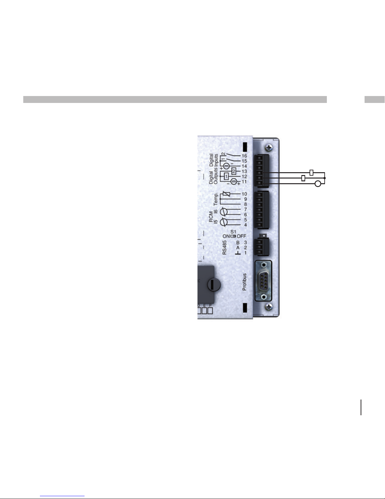
Digital inputs
The UMG 512 has two digital inputs. An input signal
is detected on a digital input if a voltage of at least 18V
and maximum 28V DC (typically at 4mA) is applied. There
is no input signal for a voltage of 0 to 5V and a current
less than 0.5 mA.
Fig. Connection
of digital outputs
-
+
-
+
24V DC
S1
S2
External
auxilliary voltage
14
15
16
2k21
2k21
2k21
2k21
2k21
Digital
Input 1
Digital
Input 2
UMG 512
Digital inputs 1-2
Fig. Example for the connection of external switch
contacts S1 and S2 to digital inputs 1 and 2.
Page 46

46
UMG 512
S0 pulse input
You can connect an S0 pulse transducer per
DIN EN62053-31 to any digital input.
This requires an external auxilliary voltage with an
output voltage in the range 18 .. 28V DC and a resistor
of 1.5kOhm.
14
15
16
2k21
2k21
2k21
2k21
2k21
Digital
Input 1
Digital
Input 2
UMG 512
Digital inputs 1-2
-
+
24V DC
External
auxilliary voltage
S0 pulse
transducer
1.5k
Page 47

47
UMG 512
Operation
The UMG 512 is operated by six function keys.
Depending on the context, the six keys are assigned
with different functions:
• Selecting measured value displays.
• Navigation within the menus.
• Editing device settings.
Labelling of
the function keys
Display title
Measured
values
Function keys
Meaning of the keys
Key Function
• Returns to the first screen (home)
• Exits selection menu
• Selects number
• Selects main values (U, I, P ...)
• Changes (number -1)
• By-values (select)
• Selects menu item
• Changes (number +1)
• By-values (select)
• Selects menu item
• Selects number
• Selects main values (U, I, P ...)
• Opens selection menu
• Confirm selection
Page 48
48
UMG 512
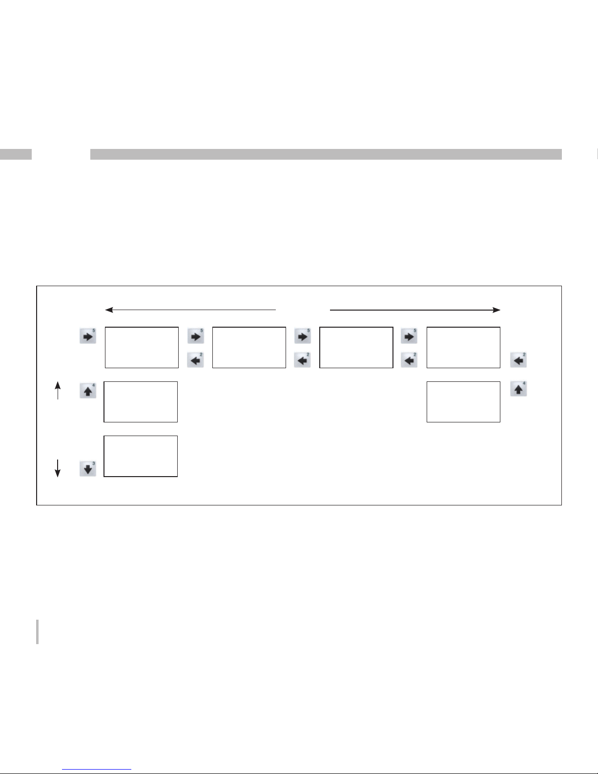
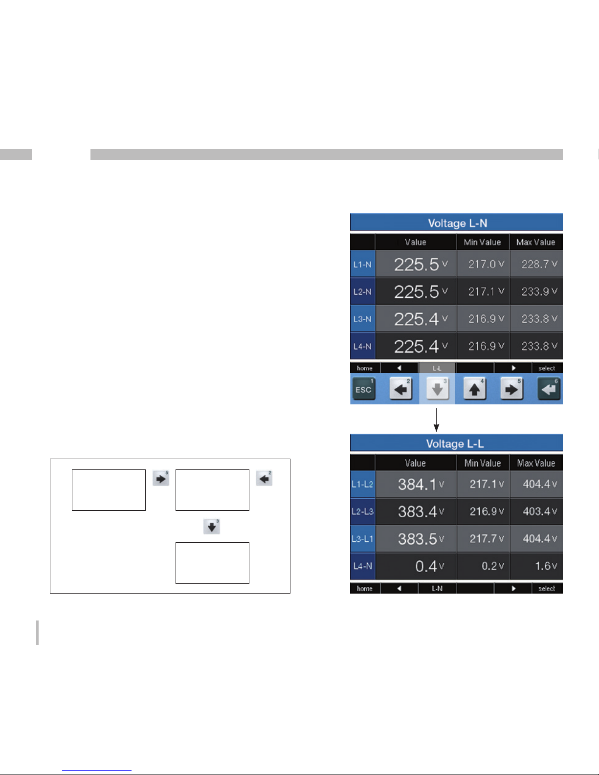
Measured value display
Main values
Using the 2 and 5 keys, you can scroll between the main
values of the measured value displays (see page
120-123).
By-values
Using the 3 and 4 keys, you can select the by-values
of a measured value display (see page 120-123).
Display
Voltage L-L
Display
Communication
Status
Display
Home
Display
Bar graph
Voltage
Display
Voltage L-N
...
...
Display
Bar graph
Current
Display
Bar graph
Effective power
Main values
By-values
Page 49

49
UMG 512
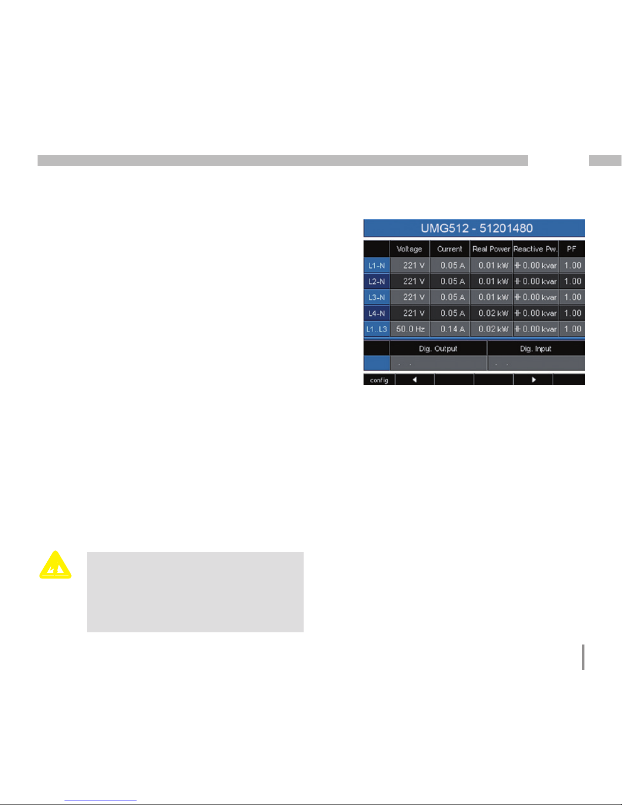
"Home" measured value display
After the power returns, the UMG 512 starts with
the "Home" measured value display.
This measured value display contains the device
names and an overview of important measured
values. In it delivery condition, the unit name consists
of the device type and the serial number of the device.
Using the "Home - key 1", you navigate
directly to the first "Home" measured value
display from the measured value displays
for the main values.
Page 50
50
UMG 512
Selecting a measured value display
You would like to switch to a measured value display
with main values.
• Using the 2 and 5 function keys, you can scroll
between the measured value displays of the main
values.
• Using the 1 (home) function key, you always navigate
to the first measured value display.
You would like to switch to a measured value display
with by-values.
• Select the measured value display with the main
values.
• Using the 3 and 4 function keys, select the measured
value display for the by-values.
Example: Selecting the voltage by-values.
Display
Home
Display
Voltage L-L
Display
Voltage L-N
... ...
Page 51

51
UMG 512
View additional information
• Using the 2 and 5 keys, scroll to the desired measured
value display.
• Activate the measured value selection using the 6 key
(select).
• The background colours for the measured value
switches from grey to green. The additional information
is displayed in blue window.
• Using the 2 and 5 keys, select the desired measured
value.
• End the procedure using the 1 key (ESC) or select
another measured value with the 2 to 5 keys.
Page 52

52
UMG 512
Deleting min./max. values individually
• Using the 2 and 5 keys, scroll to the desired measured
value display.
• Activate the measured value selection using the 6 key
(select).
• The background colours for the measured value
switches from grey to green. The additional information
is displayed in blue window.
• Using the 2 and 5 keys, select the desired minimum
or maximum value.
• The time along with the date and time of the occurrence
are displayed as additional information.
• Using the 6 key (reset), you can delete the selected
minimum or maximum value.
• End the procedure using the 1 key (ESC) or select
another minimum or maximum value with the 2 to 5
keys.
C
The date and time for the minimum/maximum values are specified displayed in
UTC time (Coordinated Universal Time).
Page 53

53
UMG 512
Transients list
The detected transients are listed in the transients list.
• The transients list consists of 2 pages.
• On page 1, the transients 1 through 8 are listed and
on page 2, the transients 9 through 16 are listed.
Displaying transients
• Using the 2 and 5 keys, scroll to the "Transient" main
value display.
• Select the desired page using the 4 key.
• Navigate to the transients list using key 6 (select)
and select a transient using the 3 or 4 keys.
• Using the 6 key (select), have a transient displayed
in a graph.
• Show or hide the legend using the 6 key (select).
• You can exit the transient graph display using the 1
key (ESC).
Transient voltages are fast impulse transient
effects in electrical networks.
The time when transient voltages occur cannot
be predicted and they have a limited duration.
Transient voltages are caused by lightning strikes,
switching operations or by tripped fuses.
Page 54

54
UMG 512
Event list
Detected events are listed in the event list.
• The event list consists of 2 pages.
• On page 1, the events 1 through 8 are listed
and on page 2, the events 9 through 16 are listed.
Displaying events
• Using the 2 and 5 keys, scroll to the "Event" main
value display.
• Select the desired page using the 4 key.
• Navigate to the event list using key 6 (select)
and select an event using the 3 or 4 keys.
• Using the 6 key (select), have an event displayed in a
graph.
• Show or hide the legend using the 6 key (select).
• You can exit the result graph display using the 1 key
(ESC).
Events are threshold value violations of effective
current and voltage values.
Page 55
55
UMG 512
Configuration
The supply voltage must be connected for
the configuration of the UMG 512.
Connecting the supply voltage
• The supply voltage level for the UMG 512 is specified
on the rating plate.
• After applying the supply voltage, a start-up display
appears. Approximately ten seconds later, the UMG
512 switches to the first "Home" measured value
display.
• If no display appears, check whether the applied
supply voltage is within the rated voltage range.
Please note!
If the supply voltage does not correspond
to the voltage indicated on the rating
plate, this may lead to malfunctions and
severe damage to the device.
c
Fig. Example of the "Home" measured value
display
Page 56
56
UMG 512
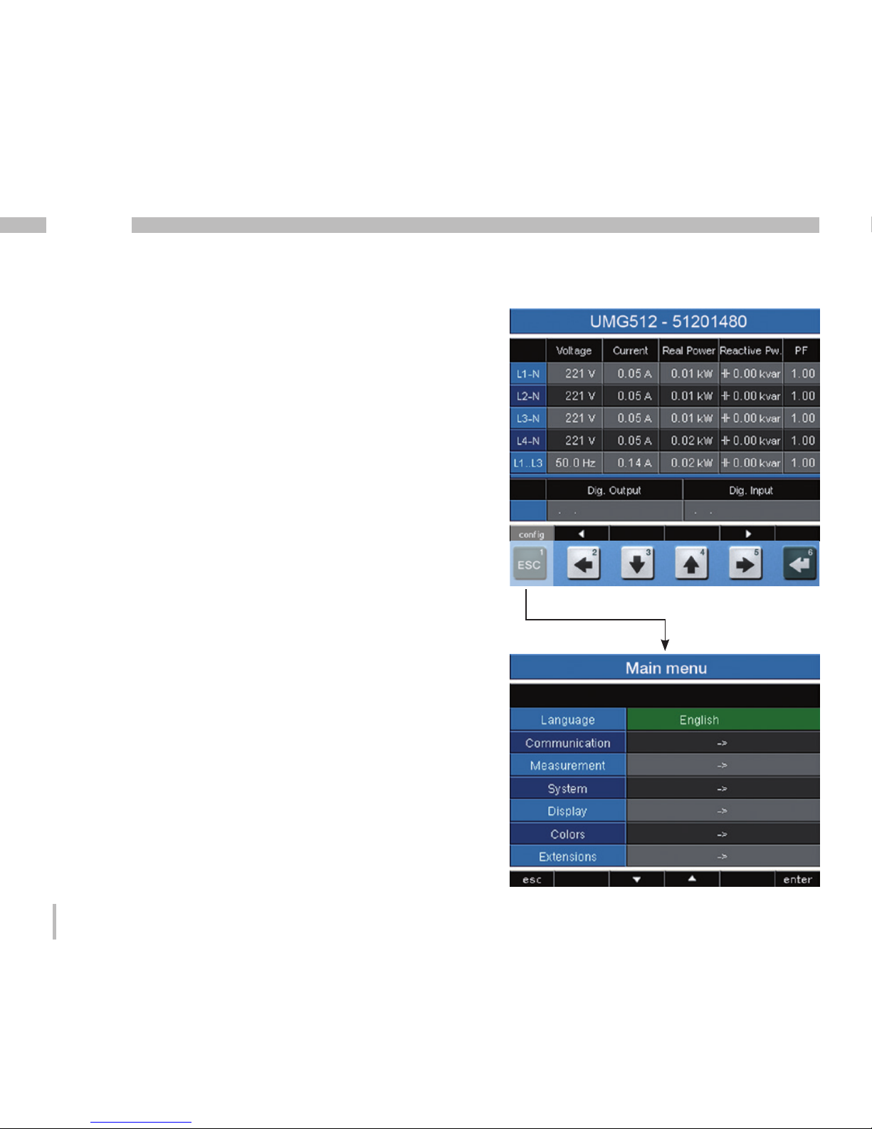
Configuration menu
After the power returns, the device starts on the "Home"
measured value display.
• Open the Configuration menu using the 1 button.
If you are in a measured value display for main values,
you can navigate directly to the "Home" measured
value display using the 1 button (home). Pressing the 1
key again opens the Configuration menu. Using the 3
or 4 keys, you select the desired submenu that can be
activated using the 6 key (enter).
Language
You can set the language for the measured value displays
and menus directly in the "Configuration" menu.
There are different languages available for selection.
The factory default setting for the language is "English".
If the language field is marked green, then the desired
language can be selected by pressing the key 6 (enter)
and the keys 3 or 4. Pressing the key 6 (enter) again
confirms the selection and changes the language.
Page 57

57
UMG 512
Communication
The UMG 512 has an Ethernet and a RS485 interface.
Ethernet (TCP/IP)
Select the type of the address assignment for
the Ethernet interface here.
DHCP mode
• Off - The IP address, netmask and gateway are
defined by the user and set directly on the UMG 512.
Select this mode for straightforward networks without
DHCP servers.
• BOOTP - BootP enables the fully automatic
integration of a UMG 512 into an existing network.
However, BootP is an older protocol and does not
provide the scope of functions provided by DHCP.
• DHCP - When started, the UMG 512 automatically
obtains the IP address, the network mask
and the gateway from a DHCP server.
Factory default setting: DHCP
Connection of the UMG 512 to the
Ethernet may only be carried out after
consulting the network administrator!
m
Page 58

58
UMG 512
RS485
You can specify the protocol, device address and baud
rate for operation with the RS485 interface. The device
address must be uniquely assigned within the bus
structure; the baud rate specification must be selected
uniformly.
The corresponding field can be selected via the keys 3 or
4 (green marking). Key 6 (enter) provides you with access
the selection options, which can then be selected with
key 3 or 4.
Pressing the 6 key (enter) again confirms the selection.
Protocol
Selection options:
• Modbus slave
• Modbus master/gateway (default setting)
• Profibus DP V0 (option)
Device address
Setting range: 0 - 255
Factory default setting: 1
Baud rate
Setting range: 9600, 19200, 38400, 57600,
115200 (default setting),
921600 kbps
Page 59
59
UMG 512
The UMG 512 has 4 measurement channels used
to measure the current (I1..I4) and 4 measurement
channels used to measure the voltage (V1..V4 against
Vref).
Measured voltage and measured current for
the measurement channels 1-4 must derive from
the same network.
Baseline measurement
The baseline measurement uses the measurement
channels 1-3. Use the measurement channels 1-3
in three-phase systems.
Supporting measurement
The supporting measurement only uses measurement
channel 4. Use measurement channel 4 when measuring
in single-phase systems or in three-phase systems with
symmetrical loads.
The frequency setting and the setting for the relevant
voltage are pulled automatically from the baseline
measurement settings.
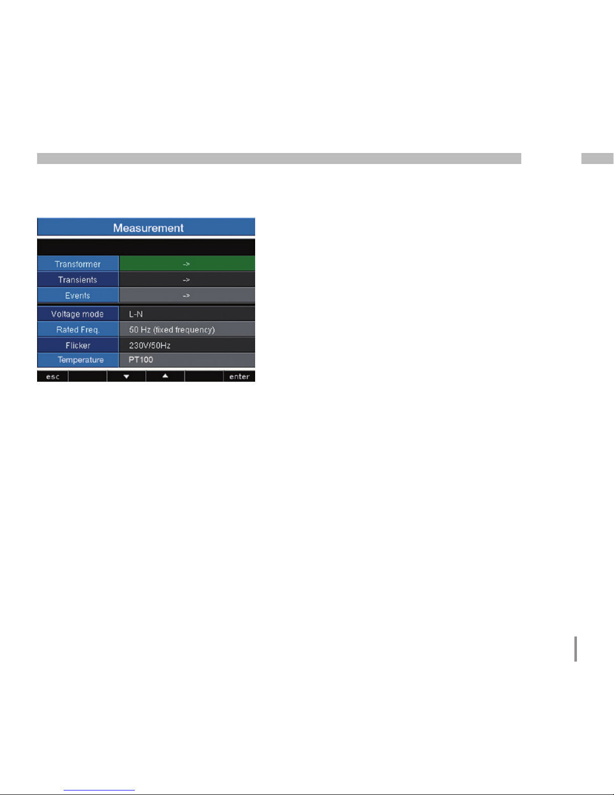
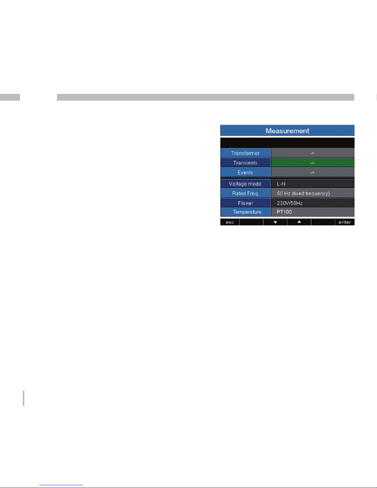
Measurement
Configure the following here:
• The measuring transducer for the current and voltage
measurement
• Recording transients
• Recording events
• The relevant voltage
• The mains frequency
• The flicker settings
Page 60

60
UMG 512
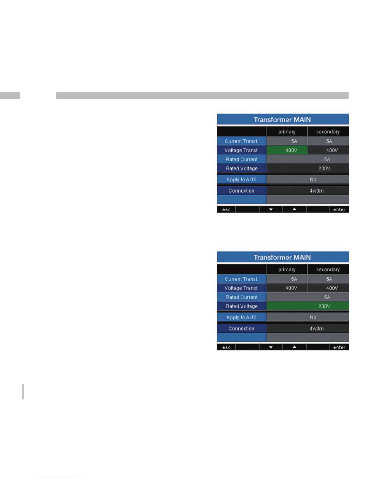
Measuring transducer
Current transformer
You can assign current transformer ratios to the baseline
measurement and the supporting measurement.
Select the 5/5A setting when measuring currents directly.
Setting range:
Primary 1 to 1000000
Secondary 1 to 5
Factory default setting:
Primary 5
Secondary 5
Rated current
The rated current defines the value to which
• Overcurrent
• Current transients
• K-factor and the
• Automatic scaling of graphics
refer.
Setting range: 0 to 1000000A
Page 61

61
UMG 512
Residual current transformer
When using residual current inputs I5 and I6, the
corresponding transformer ratios of the used residual
current transformer must be set.
Setting range:
Primary 1 to 1000000
Secondary 1
Factory default setting:
Primary 127
Secondary 1
Monitoring
Activates or deactivates the failure monitoring of the
corresponding residual current inputs.
• Activated - Switches on the failure monitoring
for residual current monitoring.
• Deactivated - Switches off the failure monitoring
for residual current monitoring.
Page 62
62
UMG 512
Voltage transformer
You can assign voltage transformer ratios to the baseline
measurement and the supporting measurement.
Select the 400/400V setting when measuring without
a voltage transformer.
Setting range:
Primary 1 to 1000000
Secondary 1 to 999
Factory default setting:
Primary 400
Secondary 400
Rated voltage
The rated voltage corresponding to the "arranged input
voltage U
din
" according to EN 61000-4-30. The rated
voltage defines the value to which
• Upward deviation (EN 61000-4-30),
• Downward deviation (EN 61000-4-30),
• Transients,
• Events and the
• Automatic scaling of graphics
refer.
Setting range: 0 to 1000000V
Factory default setting: 230V
Page 63

63
UMG 512
Connection
You can select between different connection schemes
(see page 22) for the voltage and current measurement
using the "Connection" selection.
Factory default setting: 4w3m
Fig. Example for the measurement in a threephase 4-conductor network with asymmetric
loading
Accepting AUX / MAIN
The measuring transducer can be configured
for the baseline measurement and supporting
measurement. You can accept the measuring transducer
settings in each case from the supporting or baseline
measurement.
• No - The settings from the supporting and baseline
measurement are not accepted.
• Yes - The settings from the supporting measurement
and baseline measurement are accepted.
Page 64
64
UMG 512
Transients
Transient voltages are fast impulse transient effects
in electrical networks. The time when transient voltages
occur cannot be predicted and they have a limited
duration.
Transient voltages are caused by lightning strikes,
switching operations or by tripped fuses.
• The UMG 512 detects transients that are longer than
39µs.
• The UMG 512 monitors the measurement inputs for
transients.
• There are two independent criteria by which transients
are detected.
• If a transient has been detected, the wave form will
be saved to a transient record.
• If a transient has been detected, the threshold value
increases by 20V, both in automatic and in manual
mode. This automatic increase of the threshold value
switches off within 10 minutes.
• If a further transient is detected within the next 60
seconds, it will be recorded with 512 points.
• The GridVis event browser can display recorded
transients.
Mode (absolute)
If a sampled value exceeds the set threshold value,
a transient is detected.
• Off - Transient monitoring has been switched off.
• Automatic - Factory default setting. The threshold
value is calculated automatically and is 110% of
the current 200ms effective value.
• Manual - The transient monitoring uses
the configurable threshold values under "Peak".
Page 65

65
UMG 512
Mode (delta)
If the difference between two neighbouring sampled
points exceeds the set threshold value, a transient
is detected.
• Off - Transient monitoring has been switched off.
• Automatic - Factory default setting. The threshold
value is calculated automatically and is 0.2175 times
the current 200ms effective value.
• Manual - The transient monitoring uses
the configurable threshold values under "Trns U".
Mode (envelop)
If a sampled value exceeds the envelope range,
a transient is detected.
• Off - Transient monitoring has been switched off.
• Automatic - Factory default setting. The envelop
is automatically calculated and is ±5% of the rated
voltage.
• Manual - The transient monitoring uses the
configurable envelop.
Accepting AUX / MAIN
The transient monitoring can be configured for the
baseline measurement and supporting measurement.
You can accept the settings from the supporting
or baseline measurement.
• No - The settings from the supporting and baseline
measurement are not accepted.
• Yes - The settings from the supporting measurement
and baseline measurement are accepted.
Page 66
66
UMG 512
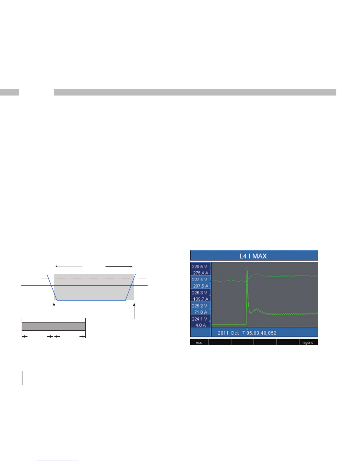
Events
Events are threshold value violations of set threshold
values for current and voltage.
Here, threshold values are compared with the half
wave effective values for current and voltage from
the measurement channels. The event record consists
of a mean value, a minimum or maximum value, a start
time and an end time.
Fig. Shows the half wave effective values for an event.
Limit value
Measured
value
Half wave
effective value
Start time event
(Trigger time)
End time
Event record
Event
Hysteresis
Hysteresis
Pre-run
After-run
• An event describes a fault due to undervoltages/
overvoltages, voltage loss, overcurrent, overfrequency/
underfrequency and rapid frequency changes
• Monitoring of the threshold values can be switched
off (Off/Manual).
• Threshold values and hysteresis must be set as
a percentage of the nominal value.
• Threshold values can be set for excess voltage,
undervoltage, voltage interruption and overcurrent.
• If an event has occurred, the corresponding measured
value is recorded with the set pre-run and after-run
periods (respectively 0..1000 half waves).
• Event records are configured with the GridVis
and displayed with the event browser.
Page 67
67
UMG 512
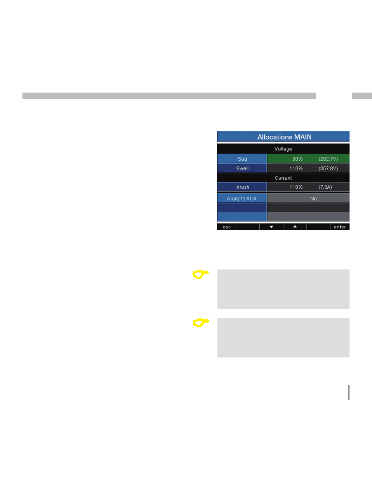
Voltage
Drop
A voltage drop is set in % of the rated voltage.
Voltage swell
The voltage swell is set in % of the rated voltage.
Current
Overcurrent
The rapid increase of current is set in % of the nominal
current.
Accepting AUX / MAIN
The event monitoring can be configured for the baseline
measurement and supporting measurement. You can
accept the settings from the supporting or baseline
measurement.
• No - The settings from the supporting and baseline
measurement are not accepted.
• Yes - The settings from the supporting measurement
and baseline measurement are accepted.
C
Lead time
You can only set the lead time with
GridVis.
Factory default setting: 0
C
After-run
You can only set the after-run with
GridVis.
Factory default setting: 0
Page 68

68
UMG 512
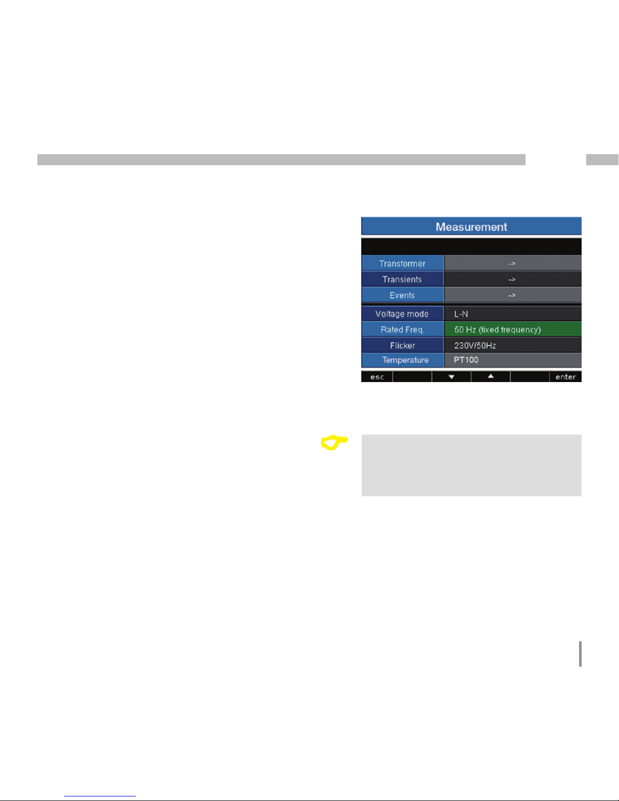
Relevant voltage
Depending on the application, the voltage between
the outer conductors (L) or the voltage between the outer
conductor (L) and the neutral conductor (N) is relevant
for analysing the power quality.
We recommend the "L-N" setting for measuring
the power quality in low voltage networks.
You should select the "L-L" setting in medium voltage
networks.
C
Flicker values can only be determined
if the relevant voltage L-N is given.
Page 69
69
UMG 512
Nominal frequency
The UMG 512 determines the mains frequency from
the voltage applied to L1 and uses this for the additional
calculations.
The nominal frequency is required as a reference for
measurement of the voltage quality.
Configure the nominal frequency for the mains
on the UMG 512 prior to starting the measurement.
Select the mains frequency 50Hz or 60Hz
for measuring the power quality in accordance with
EN61000-4-30 and EN50160.
Setting range of the nominal frequency:
• 50Hz (factory default setting)
• 60Hz
• 15Hz to 440Hz (wide range)
Set the nominal frequency to "Wide range" for
measurements in networks with other nominal
frequencies e.g. 16 2/3Hz or 400Hz.
C
In order to determine the mains
frequency, a voltage L1-N of greater
than 10Veff must be applied to voltage
measurement input V1.
Page 70
70
UMG 512
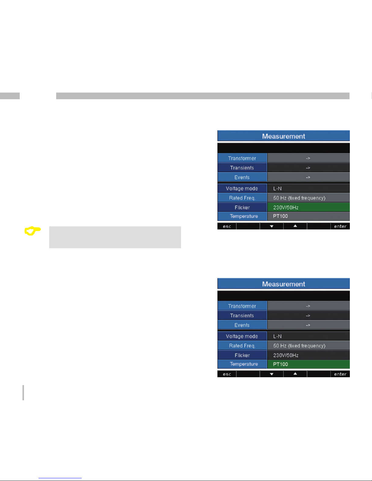
Flicker
The UMG 512 requires the mains base values in order
to provide voltage and frequency-independent
measurement and calculation of the flicker values
(flicker measurement as per DIN EN61000-4-15:2011).
These values are to be specified by the user and can be
selected from a predefined list:
• 230V/50Hz (factory default setting)
• 120V/50Hz
• 230V/60Hz
• 120V/60Hz
C
Flicker values can only be determined
if the relevant voltage L-N is given.
Temperature
When using a temperature measurement,
the corresponding sensor type must be selected from
a predefined list.
• PT100
• PT1000
• KTY83
• KTY84
Page 71

71
UMG 512
System
Display of the device-specific system settings with:
Firmware version
Serial number of the device
Fixed MAC address of the device
Set IP address
Set gateway address
Date and time
Set password
Reset settings
C
You cannot configure the date and time
directly on the device.
You can carry out the settings for the time
synchronisation and date and time with
the GridVis.
Page 72

72
UMG 512
Password
The user can block access to the configuration with
a password. The configuration can then only be changed
directly on the device by entering the password.
The password consists of a 6-digit code.
Setting range: 1-999999 = With password
000000 = Without password
Password (000000) is not factory-programmed.
• To change a password that has already been set,
you must know the current password.
• Note down the changed password.
• When selecting the "Password" (green marking),
the password can be changed using the 6 key
(enter) and keys 2 to 5. Pressing the 6 key again
confirms the entry.
• If you no longer want a password prompt, enter
the password "000000".
C
Forgot my password
If you no longer remember your password,
you can only delete it using the "GridVis"
PC software.
In order to do so, connect the UMG 512
to the PC with a suitable interface. More
information can be found in the GridVis
assistant.
Page 73

73
UMG 512
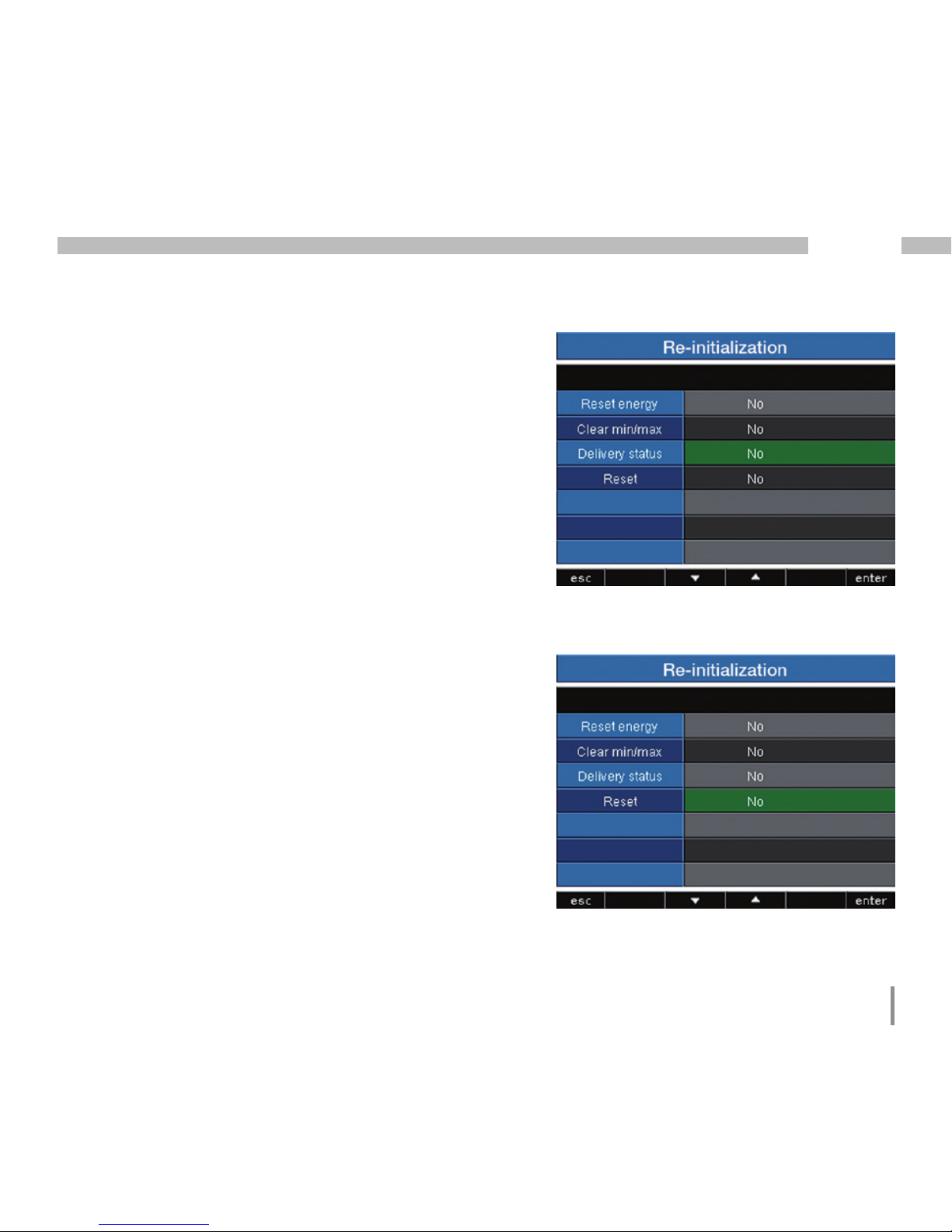
Resetting
Clearing energy meters
You can clear all energy meters in the UMG 512
at the same time using the "Reset" key.
Some specific energy meters cannot be selected.
• Highlight the "Clear energy" button (green marking)
and enable the deletion process using the key 6
(enter).
• Select "Yes" with the 4 key.
• Confirm the selection using the 6 key.
• The "Carried out" message appears in the line,
all energy meters have been cleared.
Page 74

74
UMG 512
Deleting min. and max. values
You can delete all min. and max. values in the UMG 512
at the same time using the "Reset" key.
The "Deleting minimum/maximum values individually"
section describes how you can individually delete
min. and max. values.
• Highlight the "Min/max values" item (green
marking) and enable the clear process using
the key 6 (enter).
• Select "Yes" with the 4 key.
• Confirm the selection using the 6 key.
• The "Carried out" message appears in the line,
all minimum and maximum values have been
cleared.
C
Prior to commissioning potential production dependant contents of the energy counter, min/max values and records
have to be deleted.
Page 75
75
UMG 512
Delivery status
All settings, such as the configuration and the recorded
data, are restored to the factory default settings
or deleted. Entered activation codes are not deleted.
• Select "Yes" with the 4 key.
• Confirm using the 6 key.
• The "Carried out" message appears in the line,
the delivery status is restored.
Re-initialisation
The UMG 512 is started again.
• Select "Yes" with the 4 key.
• Confirm using the 6 key.
• The device starts again within approx. 10 seconds
Page 76

76
UMG 512
Display
Brightness
The backlight brightness can be configured. The
brightness set here is used when the UMG 512 is
operated.
Setting range: 0 to 100%
Factory default setting: 70%
(0% = dark, 100% = very bright)
Standby
Time after which the brightness switches to the "Standby
brightness".
Setting range: 60 to 9999 sec.
Factory default setting: 900 sec.
Standby brightness
Brightness level the system switches to after the standby
time expires. The standby time is restarted by using keys
1-6.
Setting range: 0 to 60%
Factory default setting: 40%
Screen Saver
The screen saver prevents a screen image that is not
changed for a longer time period from "burning into"
the LCD.
Setting range: Yes, No
Factory default setting: Yes
Page 77

77
UMG 512
Screen Update
Here, you can define the speed at which the new
measured values appear in the measured value displays.
Setting range: fast (200ms), slow (1 sec.)
Factory default setting: Fast
Rotate
The measured value displays are automatically shown
one after the other. This does not affect the displays
of the configuration.
Setting range: Yes, No
Factory default setting: No
Rotation interval
Here, you can set the time after which the screen
automatically switches to the next measured value
display.
Setting range: 0 to 255 seconds
Factory default setting: 0 seconds
C
The service life of the backlight is
extended if the brightness of the backlight
is lower.
Page 78

78
UMG 512
Colours
Selection of the colours for displaying the current
and voltage in the graphic representations.
• Using the keys 3 or 4, select the desired coloured
field.
• Confirm the selection using the 6 key.
• Using the keys 3 or 4, select the desired colour.
• Confirm the selection using the 6 key.
Page 79

79
UMG 512
Extensions
Under "Extensions", you can subsequently activate
functions that are subject to purchase (activation) and
display the status of the Jasic programs (Jasic status).
Activation
The UMG 512 contains functions that are subject
to purchase and can be subsequently activated.
List of the functions that can be activated:
• BACnet
You receive the activation codes from the manufacturer.
The manufacturer requires the serial number of the device
and the name of the function to be activated.
To activate the function, enter the 6-digit activation code
in the corresponding line.
Make sure that the activation code is only valid for one
device.
Page 80

80
UMG 512
Jasic status
Up to 7 customer-specific Jasic programs (1-7) and
a recording can run in the UMG 512.
The Jasic programs can have the following statuses:
• Stopped
• Running
You cannot change the status of the Jasic programs
on the device.
Page 81
81
UMG 512
Connecting the measured voltage
• Measurement of voltages in networks with over
500VAC to earth must be connected via voltage
transformers.
• After connecting the measured voltages,
the measured values displayed by the UMG 512
for the L-N and L-L voltages must correspond
to those at the voltage measurement input.
• If a voltage transformer factor is programmed,
it must be taken into consideration for
the comparison.
Commissioning the unit
Connecting the supply voltage
• The supply voltage level for the UMG 512
is specified on the rating plate.
• After connecting the supply voltage, a display
appears. Approximately 15 seconds later, the UMG
512 switches to the first measured value display.
• If no display appears, check whether the power
supply voltage is within the rated voltage range.
Please note!
If the supply voltage does not correspond
to the voltage indicated on the rating
plate, this may lead to malfunctions
and severe damage to the device.
c
Please note!
The UMG 512 is only suitable for
use in networks where overvoltages
of overvoltage category 600V CATIII can
occur.
c
Please note!
The UMG 512 is not suitable for
measuring DC voltages.
c
C
Prior to commissioning potential production dependant contents of the energy counter, min/max values and records
have to be deleted.
Page 82

82
UMG 512
Frequency measurement
The UMG 512 requires the mains frequency for
the measurement. The mains frequency can be defined
by the user or automatically determined by the device.
• For the UMG 512 to automatically determine
the frequency, a voltage L1-N of greater than
10Veff must be applied to voltage measurement
input V1.
• The mains frequency must be in the range from
15Hz to 440Hz.
• If there is no sufficiently high measured voltage
available, the UMG 512 cannot determine
the mains frequency and thus cannot perform any
measurements.
Direction of the rotating field
Check the direction of the rotating field voltage
in the measured value display of the UMG 512.
A “right” rotation field usually exists.
Presentation of the phase sequence according to the
direction of the rotating field.
UL1-UL2-UL3 = right rotation field
UL1-UL3-UL2 = left rotation field
Page 83

83
UMG 512
Applying the measuring-circuit voltage
The UMG 512 is designed for the connection of .. /1A
and .. /5A current transformers.
Only AC currents can be measured via the current
measurement inputs - DC currents cannot.
Short circuit all current transformer outputs except for
one. Compare the currents displayed by the UMG 512
with the applied current.
Bearing in mind the current transformer conversion ratio,
the current displayed by the UMG 512 must correspond
with the input current.
The UMG 512 must display approx. zero amperes
in the short circuited current measurement inputs.
The current transformer ratio is factory-set to 5/5A
and must be adapted to the current transformer used
if necessary.
Phase shift angle sign prefix (U/I):
- Positive (+) for capacitive load
- Negative (-) for inductive load
In the Phasor diagram, the voltages are displayed
with long pointers and the currents with short
pointers.
Current
Voltage
Please note!
Voltages and currents that are outside
the permissible measuring range can
damage the device.
m
Page 84

84
UMG 512
Voltage and current have
a deviation of about 180° in
the phase position.
Phasor diagram, example 2
Predominantly ohmic load.
• The current measurement input is assigned to the
correct voltage measurement input.
• In the current measurement considered here, the k and
l connections are reversed or there is a return feed
in the mains power supply.
Voltage and current only have
a minor deviation in the phase
length.
Phasor diagram, example 1
Predominantly ohmic load.
• The current measurement input is assigned to the
correct voltage measurement input.
Page 85

85
UMG 512
Applying the residual current
Connect residual current transformer only to the I5
and I6 inputs with a rated current of 30mA! Both residual
current inputs can measure AC currents, pulsing direct
currents and DC currents.
Bearing in mind the current transformer ratio, the residual
current displayed by the UMG 512 must correspond with
the input current.
The current transformer ratio is factory-set to 5/5A
and must be adapted to the residual current transformer
used if necessary.
Failure monitoring (RCM) for I5, I6
The UMG 512 enables continuous monitoring of the
connection to the residual current transformer on inputs
I5 and I6.
Activation of failure monitoring is performed using
the corresponding menu item or by setting address
13793 for the residual-current measurement input I5
and 13795 for I6.
If there is an interruption in the connection to the current
transformer, this state is recorded in certain registers
or indicated in the GridVis software.
C
It is not necessary to configure a
connection schematic for residual current
inputs I5 and I6.
C
The UMG 512 requires the mains frequency
for residual current monitoring. For this
purpose, the measured voltage should be
applied or a fixed frequency should be set.
Modbus addr. Value / Function
13793 (I5)
13795 (I6)
Failure monitoring for I5 / I6
0 = Deactivate monitoring
1 = Activate monitoring
Modbus addr. Value / Function
13805 (I5)
13806 (I6)
0 = Connection to the residual
current transformer on to I5 or I6
error-free
1 = Error in the current transformer
connection to I5 or I6
Page 86

86
UMG 512
Alarm status for I5, I6
Using bit-by-bit coding inside the alarm register (addr.
13921 for I5, 13922 for I6), it is possible to read out
different alarm statuses:
Warning: The residual current has exceeded
the set warning limit value
Overcurrent: The measurement range has been
exceeded
Alarm: Alarm bit is set for: warning,
overcurrent or connection error
to the transformer.
The alarm bit must be reset
or acknowledged manually.
Example:
The measurement range has been exceeded. The alarm
bit is also set and must be acknowledged!
Unused
Alarm
Overcurrent
Warning
Bit:
0150 0 0 0 0 0 0
14 1312 11 10 9 8
070 0 0 0 0 0 0
6 5 4 3 2 1 0
Unused
Alarm
Overcurrent
Warning
Bit:
0150 0 0 0 0 0 0
14 1312 11 10 9 8
070 0 0 0 1 1 0
6 5 4 3 2 1 0
Page 87

87
UMG 512
Checking the power measurement
Short-circuit all current transformer outputs except for
one and check the displayed power outputs.
The UMG 512 may only display one power output
in the phase with a non-short-circuited current transformer
input. If this is not the case, check the connection of the
measured voltage and the measuring-circuit current.
If the effective power amount is correct but the sign
of the power output is negative,
• S1(k) and S2(l) could be inverted at the current
transformer
• or they supply effective power back into
the network.
Checking the communication
The UMG 512 counts all received (RX), all transmitted
(TX) and all faulty data packages.
Ideally, the number of the error displayed in the Error
column is zero.
Reset:
You can reset the meters for the data package with
the 6 key.
The start time for the new counting process is reset.
In the Phasor diagram, the voltages are displayed
with long pointers and the currents with short
pointers.
Page 88

88
UMG 512
Measurement range exceeded (overload)
If the measurement range is exceeded, it is displayed
as long as this persists and cannot be acknowledged.
The measurement range is exceeded if at least one
of the four voltage or current measurement inputs lies
outside their specified measuring range.
Threshold values for exceeding the measurement
range (200 ms effective values):
I = 7 Arms
UL-N = 600 Vrms
Indication of values exceeding the measurement
range in voltage circuit L2 and in current path I4
Page 89

89
UMG 512
RS485 interface
The MODBUS RTU protocol with CRC check
on the RS485 interface can be used to access the
data from the parameter and the measured value lists
(see RS485 configuration).
Modbus functions (master)
01 Read coil status
02 Read input status
03 Read holding registers
04 Read input registers
05 Force single coil
06 Preset single register
15 (0F Hex) Force multiple coils
16 (10Hex) Preset multiple registers
23 (17Hex) Read/write 4X registers
Modbus functions (slave)
03 Read holding registers
04 Read input registers
06 Preset single register
16 (10Hex) Preset multiple registers
23 (17Hex) Read/write 4X registers
The sequence of bytes is high before low byte (Motorola
format).
Transmission parameters:
Data bits: 8
Parity: None
Stop bits (UMG 512): 2
External stop bits: 1 or 2
Number format: short 16 bit (-2
15
to 215 -1)
float 32 bit (IEEE 754)
The message length must not exceed
256 bytes.
C
Broadcast (address 0) is not supported
by the device.
C
Page 90

90
UMG 512
Example: Reading the L1-N voltage
The L1-N voltage is saved in the measured value
list at address 19000. The L1-N voltage is available
in the FLOAT format.
Address = 01 is approved as the UMG 512 device
address.
The Query Message appears as follows:
Name Hex Note
Device address 01 UMG 512, address = 1
Function 03 „Read Holding Reg.“
Start Addr. Hi 4A 19000dez = 4A38hex
Start Addr. Lo 38
Ind. Value Hi 00 2dez = 0002hex
Ind. Value Lo 02
Error Check -
The "Response" of the UMG 512 can appear as follows:
Name Hex Note
Device address 01 UMG 512, address = 1
Function 03
Byte meter 06
Data 00 00hex = 00dez
Data E6 E6hex = 230dez
Error Check (CRC) -
The L1-N voltage read by address 19000 is 230V.
Page 91

91
UMG 512
Device master file
The device master file, abbreviated as GSD file,
describes the Profibus characteristics of the UMG 512.
The GSD file is required by the configuration program
of the PLC.
The device master file for the UMG 512 has the file name
"JAN0EDC.GSD" and is included on the data carrier
as part of the scope of the delivery.
Variable definition
All system variables and global variables1) can
be individually scaled and converted into one
of the following formats:
• 8, 16, 32 bit integer with and without sign prefix.
• 32 or 64 bit float format.
• Big or little endian.
•
Big endian = High byte before low byte.
•
Little endian = Low byte before high byte.
1)
Global variables are variables that are defined
by the user in Jasic and are available to each interface
in the UMG 512.
Profibus
Profibus profiles
A Profibus profile contains the data to be exchanged
between a UMG and a PLC. Four Profibus profiles are
preconfigured at the factory.
A Profibus profile can:
• Retrieve measured values from the UMG,
• Set the digital outputs in the UMG,
• Query the status of the digital inputs in the UMG.
Each Profibus profile can hold a maximum of 127 bytes
of data. If more data has to be transferred, simply create
additional Profibus profiles.
• Every Profibus profile has a profile number.
The profile number is sent by the PLC to the UMG.
• Using GridVis, 16 Profibus profiles (profile numbers
0..15) can be edited.
• Additional Profibus profiles (profile numbers
16..255) can be created using Jasic programs.
• Factory pre-configured Profibus profiles cannot
be subsequently changed.
Page 92

92
UMG 512
Example
Using Profibus to retrieve measured values
At least one Profibus profile must be set up with GridVis
software and transferred to the UMG 512.
A Jasic program is not required.
Fig. Block diagram for data exchange
between PLC and UMG 512.
PLC
PLC process output box
1st Byte = Profile number (0 to 15)
2nd Byte = Data to the UMG 512
•
•
PLC process input box
1st Byte = Return signal from the profile
number
2nd Byte = Requested by UMG 512 Data
•
•
UMG 512
Fetch measured values
for this profile number.
Profile number
Profile number Measured values
Profibus
Page 93

93
UMG 512
Profibus profile number 0
Byte
index
Value type Value
format
Scaling
1 1 Voltage L1-N Float 1
2 5 Voltage L2-N Float 1
3 9 Voltage L3-N Float 1
4 13 Voltage L4-N Float 1
5 17 Voltage L2-L1 Float 1
6 21 Voltage L3-L2 Float 1
7 25 Voltage L1-L3 Float 1
8 29 Current L1 Float 1
9 33 Current L2 Float 1
10 37 Current L3 Float 1
11 41 Current L4 Float 1
12 45 Effective power L1 Float 1
13 49 Effective power L2 Float 1
14 53 Effective power L3 Float 1
15 57 Effective power L4 Float 1
16 61 Cos phi (math.) L1 Float 1
17 65 Cos phi (math.) L2 Float 1
18 69 Cos phi (math.) L3 Float 1
19 73 Cos phi (math.) L4 Float 1
20 77 Frequency Float 1
21 81 Effective power sum L1-L4 Float 1
22 85 Reactive power sum L1-L4 Float 1
23 89 Apparent power sum L1-L4 Float 1
24 93 Cos phi (math.) sum L1-L4 Float 1
25 97 Effective current sum L1-L4 Float 1
26 101 Active energy sum L1-L4 Float 1
27 105 Ind. Reactive energy sum L1-L4 Float 1
28 109 THD voltage L1 Float 1
29 113 THD voltage L2 Float 1
30 117 THD voltage L3 Float 1
Factory pre-configured profiles
Profibus profile number 1
Byte
index
Value type Value
format
Scaling
1 1 Voltage L1-N Float 1
2 5 Voltage L2-N Float 1
3 9 Voltage L3-N Float 1
4 13 Voltage L2-L1 Float 1
5 17 Voltage L3-L2 Float 1
6 21 Voltage L1-L3 Float 1
7 25 Current L1 Float 1
8 29 Current L2 Float 1
9 33 Current L3 Float 1
10 37 Effective power L1 Float 1
11 41 Effective power L2 Float 1
12 45 Effective power L3 Float 1
13 49 Cos phi (math.) L1 Float 1
14 53 Cos phi (math.) L2 Float 1
15 57 Cos phi (math.) L3 Float 1
16 61 Frequency Float 1
17 65 Effective power sum L1-L3 Float 1
18 69 Reactive power sum L1-L3 Float 1
19 73 Apparent power sum L1-L3 Float 1
20 77 Cos phi (math.) sum L1-L3 Float 1
21 81 Effective current sum L1-L3 Float 1
22 85 Active energy sum L1-L3 Float 1
23 89 Ind. Reactive energy sum L1-L3 Float 1
24 93 THD voltage L1 Float 1
25 97 THD voltage L2 Float 1
26 101 THD voltage L3 Float 1
27 105 THD current L1 Float 1
28 109 THD current L2 Float 1
29 113 THD current L3 Float 1
Page 94

94
UMG 512
Profibus profile number 2
Byte
index
Value type Value
format
Scaling
1 1 Active energy sum L1-L3 Float 1
2 5 Rel. Active energy sum L1-L3 Float 1
3 9 Deliv. Active energy sum L1-L3 Float 1
4 13 Reactive energy sum L1-L3 Float 1
5 17 Ind. Reactive energy sum L1-L3 Float 1
6 21 Cap. reactive energy sum L1-L3 Float 1
7 25 Apparent energy sum L1-L3 Float 1
8 29 Active energy L1 Float 1
9 33 Active energy L2 Float 1
10 37 Active energy L3 Float 1
11 41 Inductive reactive energy L1 Float 1
12 45 Inductive reactive energy L2 Float 1
13 49 Inductive reactive energy L3 Float 1
Profibus profile number 3
Byte
index
Value type Value
format
Scaling
1 1 Effective power L1 Float 1
2 5 Effective power L2 Float 1
3 9 Effective power L3 Float 1
4 13 Effective power sum L1-L3 Float 1
5 17 Current L1 Float 1
6 21 Current L2 Float 1
7 25 Current L3 Float 1
8 29 Current sum L1-L3 Float 1
9 33 Active energy sum L1-L3 Float 1
10 37 Cos phi (math.) L1 Float 1
11 41 Cos phi (math.) L2 Float 1
12 45 Cos phi (math.) L3 Float 1
13 49 Cos phi (math.) sum L1-L3 Float 1
14 53 Reactive power L1 Float 1
15 57 Reactive power L2 Float 1
16 61 Reactive power L3 Float 1
17 65 Reactive power sum L1-L3 Float 1
18 69 Apparent power L1 Float 1
19 73 Apparent power L2 Float 1
20 77 Apparent power L3 Float 1
21 81 Apparent power sum L1-L3 Float 1
Page 95

95
UMG 512
Digital in-/outputs
The UMG 512 has two digital outputs and two digital
inputs. The inputs and outputs can be configured using
the GridVis software (included in the scope of delivery).
The settings of the functions in the configuration menu
must be made using the GridVis software.
Fig.: GridVis software, configuration menu
11 12 13
24V
DC
K1 K2
=
-
+
=
+
-
S1 S2
Digital Outputs
14 15 16
Digital Inputs
Fig.: Digital inputs and outputs
Page 96

96
UMG 512
Pulse output
The digital outputs can be used for the output
of pulses for the computation of power consumption.
For this purpose, a pulse of defined length is applied
on the output after reaching a certain, adjustable amount
of power.
You need to make various adjustments
in the configuration menu using the GridVis software
to use a digital output as a pulse out.
• Digital output,
• Measured value selection,
• Pulse length,
• Pulse value.
Fig.: GridVis software, configuration menu
Page 97

97
UMG 512
Pulse length
The pulse length applies to both pulse outputs and is set
using the GridVis software.
The typical pulse length of S0 pulse is 30ms.
Pulse interval
The pulse interval is at least as large as the selected
pulse length.
The pulse interval depends on the measured power, for
example, and can take hours or days.
Pulse length
10ms .. 10s
Pulse interval
>10ms
The values in the table are based on the minimum pulse
length and the minimum pulse interval for the maximum
number of pulses per hour.
Examples of the maximum possible number of pulses
per hour.
Pulse length Pulse interval Max. pulse/h
10 ms 10 ms 180 000 pulses/h
30 ms 30 ms 60 000 pulses/h
50 ms 50 ms 36 000 pulses/h
100 ms 100 ms 18 000 pulses/h
500 ms 500 ms 3600 pulses/h
1 s 1 s 1800 pulses/h
10 s 10 s 180 pulses/h
Measured value selection
When programming with GridVis you
have a selection of work values which are
derived from the power output values.
C
Pulse interval
The pulse interval is proportional to the
power output within the selected settings.
C
Page 98

98
UMG 512
Pulse value
The pulse value is used to indicate how much power
(Wh or varh) should correspond to a pulse.
The pulse value is determined by the maximum
connected load and the maximum number of pulses per
hour.
If you check the pulse value with a positive sign,
the pulses will only be emitted when the measured value
has a positive sign.
If you check the pulse value with a negative sign,
the pulses will only be produced when the measured
value has a negative sign.
C
Since the reactive power meter operates
with a backstop, pulses will only
be generated with inductive load applied.
Since the effective power meter operates
with a backstop, pulses will only
be generated when drawing electricity.
C
Pulse value =
max. connected load
max. number of pulses/h
[Pulse/Wh]
Page 99

99
UMG 512
Determine the pulse value
Set the pulse length
Set the pulse length in accordance with the requirements
of the connected pulse receiver.
At a pulse length of 30 ms, for example, the UMG 512
generates a maximum number of 60,000 pulses
(see Table "maximum number of pulses" per hour.
Determining the maximum connected load
Example:
Current transformer = 150/5A
Voltage L-N = max. 300 V
Power per phase = 150 A x 300 V
= 45 kW
Power at 3 phases = 45kW x 3
Max. connected load = 135kW
Calculating the pulse value
Fig.: Connection example for the circuit as pulse
output.
+ -
230V AC
24V DC
External
supply voltage
1.5k
Data logger
UMG 512
Switch and pulse outputs
+24V=
11
12
13
Pulse value = 135kW / 60,000 Imp/h
Pulse value = 0.00225 pulse/kWh
Pulse value = 2.25 pulses/Wh
C
When using the digital outputs as pulse
outputs, the auxilliary voltage (DC) must
have a max. residual ripple of 5%.
Pulse value =
max. connected load
max. number of pulses/h
[Pulse/Wh]
Page 100

100
UMG 512
Service and maintenance
The device underwent various safety checks before
delivery and is marked with a seal. If a device is open,
then the safety checks must be repeated. Warranty
claims will only be accepted if the device is unopened.
Repair and calibration
Repair work and calibration can be carried out
by the manufacturer only.
Front film
The front film can be cleaned with a soft cloth
and standard household cleaning agent. Do not use
acids and products containing acid for cleaning.
Disposal
The UMG 512 can be reused or recycled as electronic
scrap in accordance with the legal provisions.
The permanently installed lithium battery must
be disposed of separately.
Service
Should questions arise, which are not described in this
manual, please contact the manufacturer directly.
We will need the following information from you
to answer any questions:
- Device name (see rating plate),
- Serial number (see rating plate),
- Software release (see measured value display),
- Measured voltage and power supply voltage,
- Precise description of the error.
Device calibration
The devices are calibrated by the manufacturer
at the factory - it is not necessary to recalibrate
the device providing that the environmental conditions
are complied with.
Calibration intervals
We recommend having the device recalibrated
by the manufacturer or an accredited laboratory every
5 years approximately.
 Loading...