

Page 1

Part no. 33.03.217
Power Quality Analyser
UMG 509-PRO
User manual and technical data
Doc. no. 2.059.011.2.g 01/2019
www.janitza.com
Janitza electronics GmbH
Vor dem Polstück 6
D-35633 Lahnau
Support tel. +49 6441 9642-22
Fax +49 6441 9642-30
E-mail: info@janitza.com
www.janitza.com
Page 2

UMG 509-PRO www.janitza.de
1. Contents
1. General 1
1. 1 Disclaimer 1
1. 2 Copyright notice 1
1. 3 Technical changes 1
1. 4 Declaration of conformity 1
1. 5 Comments on the manual 1
1. 6 Meaning of symbols 1
2. Safety 3
2. 1 Safety information 3
2. 2 Safety measures 4
2. 3 Qualified staff 4
3. Proper use 5
3. 1 Inspection on receipt 5
3. 2 Scope of delivery 6
3. 3 Available accessories 6
4. Product description 7
4. 1 Measuring process 7
4. 2 Usage concept 7
4. 3 GridVis® network analysis software 7
4. 4 Features 8
4. 5 Product overview 9
5. Installation 11
5. 1 Installation location 11
5. 2 Installation position 11
5. 3 Mounting 11
6. Network systems 13
6. 1 Three-phase 3-conductor systems 14
6. 2 Three-phase 4-conductor systems 14
6. 3 Rated voltages 15
6. 3. 1 Three-phase 4-conductor network with earthed neutral conductor 15
6. 3. 2 Three-phase 3-conductor network, non-earthed 15
I
Page 3

www.janitza.de UMG 509-PRO
7. Installation 17
7. 1 Connection to a PC 17
7. 2 Ground wire connection 18
7. 3 Disconnectors 18
7. 4 Supply voltage 18
7. 5 Measured voltage 19
7. 5. 1 Overvoltage 19
7. 5. 2 Frequency 19
7. 6 Current measurement 20
7. 6. 2 Current direction 21
7. 6. 3 Total current measurement 21
7. 6. 1 Ammeter 21
7. 7 Connection variants 22
7. 7. 1 Voltage measurement 22
7. 7. 2 Current measurement 23
7. 7. 3 Supporting measurement, input V4 24
7. 8 Residual current monitoring 25
7. 8. 1 Failure monitoring 25
7. 8. 2
Example: Residual current transformer insulation 26
7. 9 Temperature measurement 27
7. 9. 1 Example: Temperature sensor insulation 27
8. Interfaces 29
8. 1 Shielding 29
8. 2 RS485 interface 30
8. 2. 1 Termination resistors 30
8. 3 Profibus interface 31
8. 3. 1 Connecting the bus lines 31
8. 4 Bus structure 32
8. 5 Ethernet interface 33
9. Digital inputs and outputs 35
9. 1 Digital inputs 35
9. 1. 1 S0 pulse input 36
9. 2 Digital outputs 37
10. Operation 39
10. 1 Button allocation 39
10. 2 “Home" measured value indication 39
10. 3 Measured value indication 40
10. 3. 1 Main values 40
10. 3. 2 By-values 40
10. 4 Selecting a measured value indication 41
10. 5 View additional information 42
10. 6 Deleting values 42
10. 7 Transients list 43
10. 8 Event list 44
II
Page 4

UMG 509-PRO www.janitza.de
11. Configuration 45
11. 1 Languages 45
11. 2 Communication 45
11. 2. 1 Ethernet(TCP/IP) 45
11. 2. 2 Field bus 46
11. 3 Measurement 47
11. 3. 1 Measuring transducer 47
11. 3. 2 Transients 51
11. 3. 3 Events 53
11. 3. 4 Mains frequency 54
11. 4. 2 Temperature 55
11. 4 System 55
11. 4. 1 Password 56
11. 4. 3 Reset 56
11. 5 Display 58
11. 6 Colours 59
11. 7 Extensions 59
12. Commissioning 61
12. 1 Connecting the supply voltage 61
12. 2 Connecting the measured voltage 61
12. 3 Frequency measurement 62
12. 4 Phase sequence 62
12. 5 Applying the measured current 63
12. 5. 1 Phasor diagram examples 64
12. 6 Applying the residual current 64
12. 7 Failure monitoring (RCM) 65
12. 7. 1 Alarm status 65
12. 8 Measurement range exceeded 66
12. 9 Checking the power measurement 66
12. 10 Checking the communication 66
12. 11 Communication in the bus system 67
12. 11. 1 RS485 67
12. 11. 2 Profibus 68
12. 12 Digital inputs/outputs 73
12. 12. 1 Digital inputs 73
12. 12. 2 Pulse output 73
III
Page 5

www.janitza.de UMG 509-PRO
13. Device homepage 77
13. 1 Measured values 78
13. 1. 1 Short overview 78
13. 1. 2 Detailed measured values 79
13. 1. 3 Diagrams 80
13. 1. 4 RCM - residual current monitoring 80
13. 1. 5 Events 81
13. 1. 6 Transients 81
13. 2 Power quality 82
13. 3 Apps 83
13. 3. 1 Push Service 83
13. 4 Information 84
13. 4. 1 Device information 84
13. 4. 2 Display 84
13. 4. 3 Downloads 84
14. Service and maintenance 85
14. 1 Repair and calibration 85
14. 2 Front film 85
14. 3 Disposal 85
14. 4 Service 85
14. 5 Device calibration 85
14. 6 Calibration intervals 85
14. 7 Firmware update 85
14. 8 Battery 86
15. Procedure in the event of faults 87
16. Technical data 89
16. 1 Supply voltage 89
16. 2 Voltage and current measurement 90
16. 3 Residual current monitoring 91
16. 4 Temperature measurement input 92
16. 5 Digital inputs and outputs 93
16. 6 Interfaces 94
16. 7 Function parameters 95
16. 8 Dimension diagrams 96
17. Menu guide overview 97
17. 1 Configuration menu overview 97
17. 2 Overview of measured value indications 98
18. Connection example 101
IV
Page 6

UMG 509-PRO www.janitza.de
1. General
1. 1 Disclaimer
Observing the information products
for the devices is the prerequisite for safe
operation and in order to obtain the specified
performance and product features. Janitza
electronics GmbH accepts no liability
for injuries to personnel, property damage
or financial losses arising due to a failure
to comply with the information products.
Ensure that your information products are
accessible and legible.
1. 2 Copyright notice
© 2017 - Janitza electronics GmbH - Lahnau.
All rights reserved.
Duplication, editing, dissemination and other
utilisation, also in part, is prohibited.
All trademarks and the resulting rights
are the property of their respective owners.
1. 3 Technical changes
• Please ensure that your device complies
with the installation manual.
• Please read and understand
the documents enclosed with the product
first.
• Keep the documents enclosed with
the product available throughout the entire
service life of the product and pass them
on to subsequent users if applicable.
• Inform yourself of any new device versions
and the associated updates to the
documentation enclosed with the product
at www.janitza.de.
1. 4 Declaration of conformity
For information on the laws, standards and
directives that Janitza electronics GmbH has
applied for the device, see the declaration
of conformity on our website
(www.janitza.de).
1. 5 Comments on the manual
We welcome your comments. If anything
in this manual seems unclear, please let
us know by sending us an e-mail to:
info@janitza.de
1. 6 Meaning of symbols
This manual uses the following pictograms:
Ground wire connection.
Inductive.
The current lags behind the voltage.
Capacitive.
The voltage lags behind the current.
1
Page 7

www.janitza.de UMG 509-PRO
2
Page 8
UMG 509-PRO www.janitza.de
2. Safety
Please read this user manual and all other
publications that must be consulted to work
with this product. This applies particularly
to installation, operation and maintenance.
Observe all safety instructions and warnings.
Failure to comply with the instructions can
result in personal injuries and/or damage
to the product.
Any unauthorised changes or use
of this device, which go beyond
the mechanical, electrical or otherwise stated
operating limitations, can result in bodily
injury and/or damage to the product.
Any such unauthorised change constitutes
"misuse" and/or "negligence" according
to the warranty for the product and thus
excludes the warranty for covering possible
damage resulting from this.
The user manual:
• must be read before using the device.
• must be kept throughout the entire service
life of the product and be readily available
for reference.
2. 1 Safety information
Symbols used:
This symbol is used as an addition
c
C
Safety information is highlighted by a warning
triangle and is indicated as follows depending
on the degree of danger:
m
DANGER!
m
WARNING!
m
CAUTION!
to the safety instructions and warns
of an electrical hazard.
This symbol with the word note
describes:
• Procedures that do not pose
any risk of injures.
• Important information,
procedures or handling steps.
Indicates an imminent danger
that causes severe or fatal
injuries.
Indicates a potentially
hazardous situation that can
cause severe injuries or death.
Indicates a potentially
hazardous situation that can
cause minor injuries or damage
to property.
Follow additional legal and safety regulations
required for the respective application when
using the device.
3
Page 9

www.janitza.de UMG 509-PRO
2. 2 Safety measures
When operating electrical devices, certain
parts of these devices are invariably
subjected to hazardous voltage. Therefore,
severe bodily injuries or damage to property
can occur if they are not handled properly:
c
WARNING!
Severe bodily injuries or death can occur
due to dangerous voltages.
Therefore, note the following:
• Before connecting connections,
earth the device at the ground wire
connection if present.
• Hazardous voltages may be present
in all switching parts that are
connected to the power supply.
• Hazardous voltages may also
be present in the device even after
disconnecting the supply voltage.
• Provide single core conductors with
sleeves.
• Only connect screw-type terminals
with a matching number of pins
and of the same type.
• If the device is not operated according
to the documentation, protection
is no longer ensured and hazards
can be posed by the device.
• De-energise the system before
starting work.
Risk of injury due
to electric voltage!
2. 3 Qualified staff
This device must only be operated
and repaired by specialised personnel.
Specialised personnel are people who are
qualified to recognise risks and prevent
potential dangers that can be caused
by the operation or maintenance
of the device based on their respective
training and experience.
4
Page 10

UMG 509-PRO www.janitza.de
3. Proper use
3. 1 Inspection on receipt
The prerequisites of faultless, safe operation
of this device are proper transport and proper
storage, set-up and installation, as well
as careful operation and maintenance.
Packing and unpacking must be carried
out with customary care without the use
of force and only using suitable tools.
Visually inspect the devices for flawless
mechanical condition.
Please check the delivered items
for completeness before you start installing
the device.
If it can be assumed that risk-free operation
is no longer possible, the device must
be immediately put out of operation
and secured against being put back
into operation again. It can be assumed
that risk-free operation is no longer possible
if the device, for example:
C
C
NOTE!
All screw-type terminals included
in the scope of delivery are attached
to the device.
NOTE!
All supplied options and versions
are described on the delivery note.
• has visible damage.
• no longer works despite the mains power
supply being intact.
• has been exposed to prolonged
adverse conditions (e.g. storage outside
the permissible climate limits without
being adapted to the room climate,
condensation, etc.) or rough handling
during transportation (e.g. falling from
a height, even if there is no visible external
damage, etc.).
5
Page 11

www.janitza.de UMG 509-PRO
3. 2 Scope of delivery
Number Part no. Designation
1 52.26.xxx
1 33.03.320 Installation manual
1 33.03.348 “GridVis software” quick guide
1 10.01.855 Screw-type terminal, pluggable, 2-pin (auxiliary supply)
1 10.01.847 Screw-type terminal, pluggable, 5-pin (voltage measurement 1-4)
1 10.01.853 Screw-type terminal, pluggable, 8-pin (current measurement 1-4)
1 10.01.873 Screw-type terminal, pluggable, 6-pin (digital inputs/outputs)
1 10.01.888 Screw-type terminal, pluggable, 7-pin (RCM, thermistor input)
1)
UMG 509-PRO
1 10.01.859 Screw-type terminal, pluggable, 3-pin (RS 485)
1 08.01.505 2m patch cable, twisted, grey (UMG PC/switch connection)
1 52.19.301 Mounting clips
1)
For the item number, see the delivery note
3. 3 Available accessories
Part no. Designation
21.01.102 CR2450 lithium battery, 3 V (approval according to UL 1642)
13.10.539 Profibus connector, 9-pin, D-SUB
13.10.543 Profibus connector, 9-pin, D-SUB, wound
29.01.903 Seal, 144 x 144
6
Page 12
UMG 509-PRO www.janitza.de
4. Product description
The device is:
• intended for measurement in building
installations, on distribution units, circuit
breakers and busbar trunking systems.
• suitable for installation in fixed
and weatherproof switchboards.
• usable in 2, 3 and 4-conductor networks
and in TN and TT networks.
• provided with external ../1 A or ../5 A
current transformers for current
measurement.
• only suitable for measurements in medium
and high-voltage networks via current and
voltage transformers.
• suitable for use in residential and industrial
applications.
• suitable for residual current monitoring
(RCM) via external residual current
transformers with a rated current of 30 mA.
• suitable for measuring measured voltages
and measured currents that derive from
the same network.
The measurement results can be displayed,
saved, read out and further processed
via the device's interfaces.
4. 1 Measuring process
The device:
• measures continuously and calculates
all effective values over a 200 ms interval.
• measures the real effective value (TRMS)
of the voltages and currents connected
to the measurement inputs.
4. 2 Usage concept
You can program and call up the measured
values via many routes using the device:
This operation manual only describes how
to operate the device using the 6 buttons.
The GridVis® network analysis software
has its own "online help".
4. 3 GridVis® network analysis software
You can use the GridVis® network analysis
software that is available at www.janitza.
de to program the device and read out
data. To do this, a PC must be connected
to the device via a serial interface (RS485/
Ethernet).
You can use the GridVis® network analysis
software to:
• program the device.
• configure and read out recordings.
• analyse the read out data according
to EN 61000-2-4.
• save the data to a database.
• display measured values graphically.
• program customer-specific applications.
c
CAUTION!
If the device is connected incorrectly,
incorrect measured values may be returned.
Therefore, note the following:
• Measured voltages and measured
currents must derive from the same
network.
• Do not use the device to measure
DC current.
• Earth active switchboards.
Malfunctions due
to incorrect connection
• directly on the device via 6 buttons
and the display.
• using the GridVis® programming
software.
• using the device homepage.
• using the Modbus protocol. You
can modify and call up the data using
the Modbus address list. The list can
be called up from www.janitza.de.
7
c
CAUTION!
Residual current monitoring monitors residual
currents via external current transformers
and can trigger a warning impulse
when a threshold value is exceeded.
The device is therefore
not anindependent protective device
against electric shocks.
Risk of injury due
to electric voltage
Page 13

www.janitza.de UMG 509-PRO
4. 4 Features
General
• Front panel integration device with dimensions 144 x 144 mm
• Connection via pluggable screw terminals
• Colour graphic display 320x240, 256 colours
• Operation via 6 buttons
• 4 voltage and 4 current measurement inputs
• 2 residual current inputs with failure monitoring
• 1 temperature measurement input
• 2 digital outputs and 2 digital inputs
• 16-bit A/D converter, memory 256 Mbyte Flash, SDRAM 32 Mbyte
• RS485 interface (Modbus RTU, slave, up to 921 kbps)
• Profibus DP/V0
• Ethernet (web server, e-mail)
• Capture more than 2000 measured values
• Clock and battery
• Working temperature range -10 °C to +55 °C
Measurement
• Measurement in TN and TT networks
• Continuous sampling of the voltage and current measurement inputs at 20 kHz
• Capture transients >50 µs and store up to approx. 330,000 sampling points
• Current metering range 0.001 to 7 Amps
• Real effective value measurement (TRMS)
• Continuous sampling of the voltage and current measurement inputs
• Continuous monitoring of residual currents with failure monitoring
• Temperature measurement
• Working measurement, measurement uncertainty in accordance
with DIN EN50470-3:
- Class C for ../5 A converter
- Class B for ../1 A converter
• Measurement of the harmonics 1st to 63rd for:
- Ull, Uln, I, P (consumption/delivery) and Q (ind./cap.)
• Analysis and evaluation in accordance with DIN EN 50160 with the GridVis®
programming software supplied as standard
• Programming separate applications in Jasic
8
Page 14

UMG 509-PRO www.janitza.de
4. 5 Product overview
1
2
Fig. Front view of UMG 509 -PRO
3
4
5
1 Device type
2 Description of the function keys
3 Button 1: Configuration menu, back
4 Button 2: Select number, switch between main values
5 Button 3: Reduce the number by 1, select menu item
6 Button 4: Increase the number by 1, select menu item
7 Button 5: Select number, switch between main values
8 Button 6: Activate input, confirm selection
8
7
6
9
Page 15

www.janitza.de UMG 509-PRO
1
2
5
6
3
7
8
9
4
Fig. Rear view of UMG 509 -PRO
1 Ground wire connection
2 Supply voltage
3 Current measurement inputs I1 to I4
4 Voltage measurement inputs V1 to V4, Vn
5 Digital inputs / outputs
6 Thermistor inputs
7 Residual current monitoring inputs I5 and I6
8 DIP switch S1
9 RS485 interface
10 Profibus interface
11 Battery compartment
10
11
10
Page 16

UMG 509-PRO www.janitza.de
5. Installation
5. 1 Installation location
The device is suitable for installation in fixed
and weatherproof switchboards.
Earth active switchboards.
Damage to property due
m
CAUTION!
to a failure to adhere to
the installation instructions!
Failing to observe the installation instructions
can damage or destroy your device.
Adhere to the specifications for
the installation position in sections „5.
Montage“ and „16. Technische Daten“.
5. 2 Installation position
The cut-out dimension in the switchboard is
138
+0.8
mm x 138
+0.8
mm.
To ensure adequate ventilation, adhere
to the following specifications:
• install the device vertically.
• keep a gap of 50 mm at the top
and bottom.
• keep a minimum gap of 20 mm.
5. 3 Mounting
The device is mounted in the switchboard
with two mounting clips at the top
and bottom. Attach the mounting clips
to the device in advance.
Fig. Arrangement of the mounting clips on thee
UMG 509-PRO
Wall
Airflow
Airflow
Fig. Rear view of the UMG 509-PRO installation position
11
Page 17

www.janitza.de UMG 509-PRO
12
Page 18

UMG 509-PRO www.janitza.de
L1
EE
E
L1
L2
L3
E
N
R
L1
L2
L3
EE
L1
L2
L3
EE
E
L1
E
L1
L2
L3
EE
L1
L2
L3
EE
L1
EE
L1
L2
L3
EE
L1
EE
L1
L2
L3
EE
N
E
L1
L2
L3
E
N
R
L1
L2
L3
EE
L1
EE
L
N
EE
L1
L2
L3
EE
L1
L2
N
EE
E
L1
L2
L3
E
N
R
L1
L2
L3
EE
EE
L1
L2
L3
EE
L1
L2
N
EE
L1
L2
L3
EE
L1
L2
L3
EE
L1
EE
6. Network systems
Network systems and maximum rated voltages in accordance with DIN EN 61010-1/A1:
Three-phase four-conductor
systems
with earthed neutral conductor
L2
N
L3
U
/ U
L-N
L-N
/ U
L-L
L-L
: 417 VLN / 720 VLL
: 347 VLN / 600 VLL
IEC
UL
U
Dual-phase two-conductor
systems
not earthed
L2
Three-phase four-conductor
systems
with non-earthed
Three-phase three-conductor
systems
not earthed
Three-phase three-conductor
neutral conductor (IT networks)
L2
N
R
L3
L2
L3
Only partially suitable for use in non-earthed networks U
Single-phase two-conductor
systems
with earthed neutral conductor
L
N
Separated single-phase
three-conductor system
with earthed neutral conductor
N
L2
Application areas for the device:
• 2, 3 and 4 conductor
• Domestic and industrial
systems
with earthed phase
L2
L3
L-L
600 VLL
networks
(TN and TT networks).
applications.
Only partially suitable for use
in non-earthed networks
c
WARNING!
Risk of injury due
to electric voltage!
IEC
UL
U
U
L-N
L-N
480 VLN
480 VLN
IEC
UL
U
/ U
L-N
U
/ U
L-N
: 400 VLN / 690 VLL
L-L
: 347 VLN / 600 VLL
L-L
If the device is subjected to measurement
voltage surges higher than the permissible
overvoltage category, safety-relevant
insulations in the device can be damaged,
which means that the product’s safety can
no longer be guaranteed.
Only use the device in environments
13
in which the permissible measurement
voltage surge is not exceeded.
Page 19
www.janitza.de UMG 509-PRO
6. 1 Three-phase 3-conductor systems
The device is only suitable to a limited extent
for use in IT networks, as the measured
voltage relative to the housing potential
is measured and the input impedance
of the device creates residual current against
the earth. The residual current can trigger
insulation monitoring in IT networks.
The connection variants with voltage
transformers are suitable for unlimited use
in IT networks.
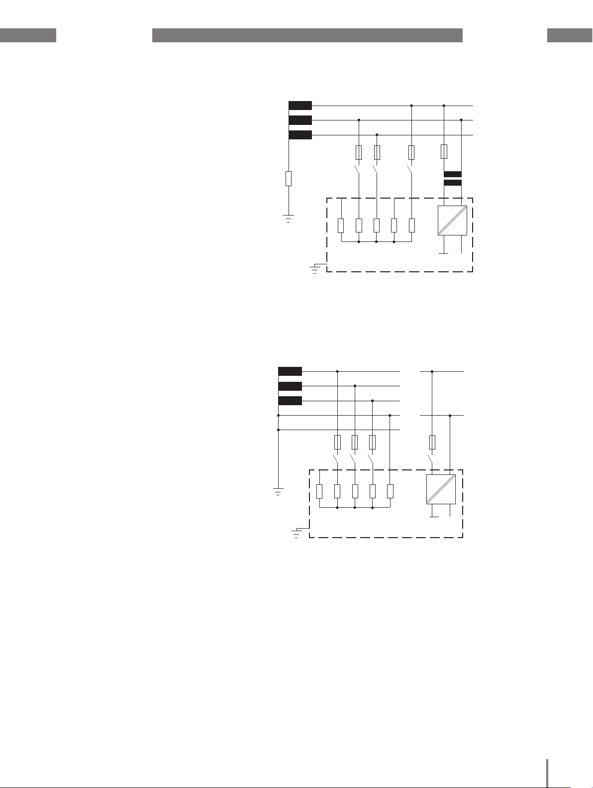
6. 2 Three-phase 4-conductor systems
The device can be used in three-phase
4-conductor systems (TN, TT networks)
with an earthed neutral conductor.
The bodies of the electrical system
are earthed.
Voltage measurement in the device
is designed for overvoltage category 600 V
CAT III (measurement voltage surge 6 kV).
L1
L2
L3
Impedance
Earthing of
the system
Fig. Schematic diagram, UMG 509-PRO in an IT network
without N.
L1
L2
L3
N
PE
System
earthing
600V 50/60Hz
V1
V4
4M
4M
4M
Voltage measurement
UMG 509-PRO
347V/600V 50/60Hz
V1 V3V2 Vref
V4
4M
4M
4M
Voltage measurement
UMG 509-PRO
4M
V3V2
Vref
4M
4M
Auxilliary power
L1
N
AC/DC
4M
Auxilliary power
240V
50/60Hz
AC/DC
DC
DC
Fig. Schematic diagram, UMG 509-PRO in a TN
network.
14
Page 20

UMG 509-PRO www.janitza.de
6. 3 Rated voltages
The following illustrations show lists
of networks and the corresponding rated
network voltages in which the device can
be used.
6. 3. 1 Three-phase 4-conductor network
with earthed neutral conductor
U
/ U
L-N
L-L
66V / 115V
120V / 208V
127V / 220V
220V / 380V
230V / 400V
240V / 415V
260V / 440V
277V / 480V
347V / 600V
400V / 690V
417V / 720V
Fig. Rated network voltages that are suitable for
measurement inputs in accordance with EN 60664-1:2003
Maximum network rated voltage
according to UL
Maximum network rated voltage
6. 3. 2 Three-phase 3-conductor
network, non-earthed
U
L-L
66V
115V
120V
127V
200V
220V
230V
240V
260V
277V
347V
380V
400V
415V
440V
480V
500V
577V
600V
Maximum network rated voltage
Fig. Rated network voltages that are suitable for
measurement inputs in accordance with EN 60664-1:2003
15
Page 21

www.janitza.de UMG 509-PRO
16
Page 22

UMG 509-PRO www.janitza.com
7. Installation
7. 1 Connection to a PC
You have the following options for connecting
the device to a PC:
1. Connection via an interface converter:
PC with GridVis®
UMG 509-PRO
RS232
RS232
RS485
RS485
3. Connection via the network:
PC with GridVis®
Ethernet
UMG 509-PRO
Ethernet
2. Direct connection via Ethernet: 4. Using the UMG 509-PRO as a gateway
for additional UMGs
PC with GridVis®
UMG 509-PRO
PC with GridVis®
17
Ethernet
UMG 509-PRO
as gateway
Ethernet
UMG 104
Slave 1
Ethernet
UMG 103
Slave 2
ModbusModbus Modbus
UMG 604
Slave 3
Page 23
www.janitza.com UMG 509-PRO
7. 2 Ground wire connection
Use a ring cable lug to connect the ground
wire connection to the device.
7. 3 Disconnectors
During building installation, provide a suitable
disconnector for the supply voltage in order
to disconnect the device from the current
and voltage.
• Install the disconnector close to the device
so that it is easily accessible to the user.
• Label the switch as a disconnection device
for this device.
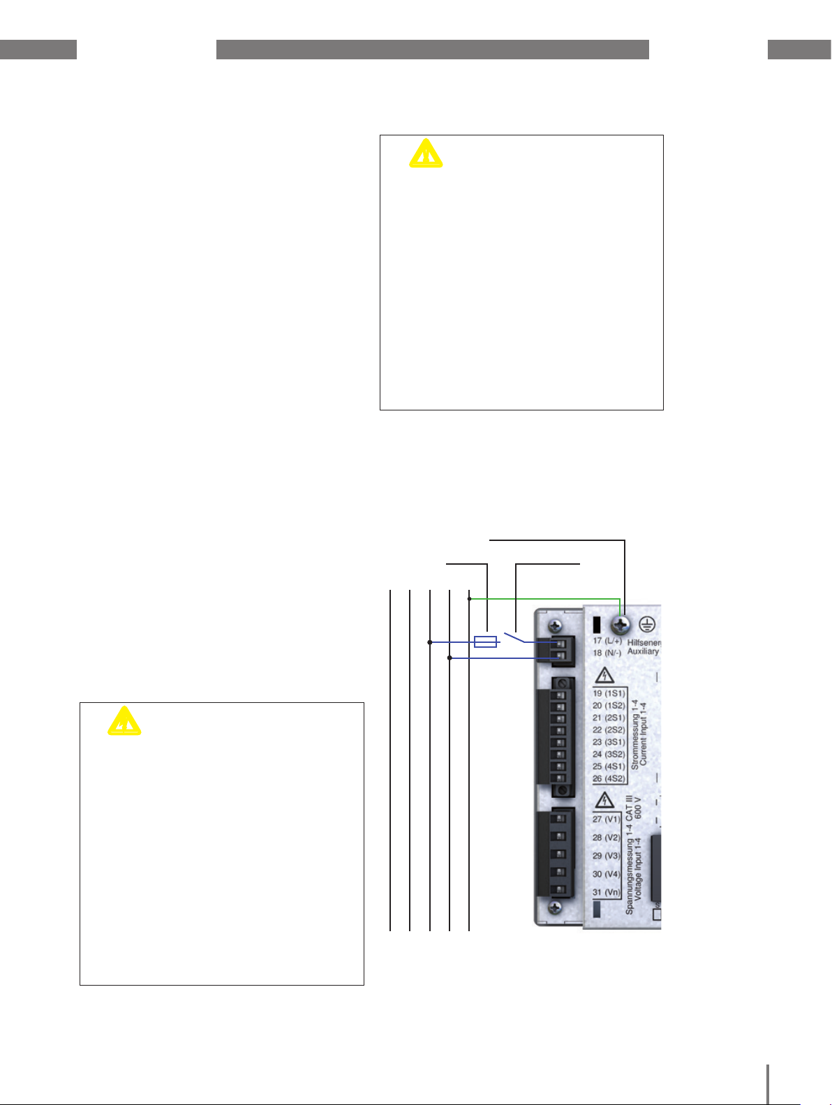
7. 4 Supply voltage
The device requires supply voltage
to operate. The supply voltage type and level
for your device are specified on the rating
plate.
The supply voltage is connected via terminal
blocks on the rear of the device.
Before connecting the supply voltage, ensure
that the voltage and frequency correspond
to the details on the rating plate.
Connect the supply voltage via a UL/IEC
approved fuse.
m
CAUTION!
Failure to observe the connection conditions
can damage or destroy your device.
Therefore, note the following:
• Adhere to the specifications for voltage
and frequency on the rating plate.
• Connect the supply voltage via a fuse
in accordance with the technical data.
• Do not connect the supply voltage to
the voltage transformers.
• Provide a fuse for the neutral
conductor if the source's neutral
conductor connection is not earthed.
L1 N PEL3L2
Damage to property
due to not observing
the connection conditions
Connection point for the ground wire
Fuse
Isolation device
Ground wire
c
WARNING!
Severe bodily injuries or death can occur
due to:
• touching bare or stripped wires that are
live,
• device inputs that are dangerous
to touch.
Therefore, note the following:
• The inputs for the supply voltage are
hazardous if touched.
• De-energise your system before
starting the work!
• Connect the device’s ground wire
connection to the system earthing.
Risk of injury due
to electric voltage!
Fig. Example connection for the supply voltage
18
Page 24

UMG 509-PRO www.janitza.com
7. 5 Measured voltage
The device has 4 voltage measurement
inputs (V1 to V4) that are located on the rear
of the device.
• V1 to V3 for the baseline measurement.
• V4 for the supporting measurement
The connections are called supporting
and baseline measurement below.
7. 5. 1 Overvoltage
The voltage measurement inputs are suitable for
measurements in networks where overvoltages
of category 600 V CAT III can occur.
7. 5. 2 Frequency
The device:
• is suitable for measurements in networks
in which the fundamental oscillation
of the voltage is in the range of 40 Hz
to 70 Hz.
• only measures the frequency on
measurement inputs V1, V2 and V3.
c
WARNING!
Severe bodily injuries or death can occur
due to a failure to observe the connection
conditions for the voltage measurement
inputs.
Therefore, note the following:
• Do not use the device for voltage
measurement in SELV circuits
(safe extra low voltage).
• Connect the voltages higher than
the permitted network rated voltages
using voltage transformers.
• The voltage measurement inputs
on the device are dangerous
if touched!
• Install a disconnector as described
in “7. 3 Disconnectors”.
• Use a UL/IEC-approved overcurrent
protection with a rated value, which
is suitable for the short circuit current
at the connection point.
Risk of injury due
to electric voltage!
L1 N PEL3L2
10A
(UL/IEC listed)
Fig. Connection example for voltage measurement.
C
C
If the device is connected incorrectly,
incorrect measured values may be returned.
Therefore, note the following:
NOTE!
It is not necessary to configure
a connection schematic for
measurement inputs V4 and I4.
NOTE!
For measurement with the supporting
measurement, a voltage must be
connected to the baseline measurement
for frequency determination.
c
CAUTION!
• Measured voltages and currents must
derive from the same network.
• The device is not suitable
for measuring DC voltage.
Malfunction due
to incorrect connection
19
Page 25

www.janitza.com UMG 509-PRO
7. 6 Current measurement
The device:
• is intended for connecting current
transformers with secondary currents
of ../1 A and ../5 A.
• does not measure DC.
• has current measurement inputs that are
loaded with 120 A for 1 second.
The factory-set current transformer ratio
is 5/5 A and must be adapted to the current
transformer employed if necessary.
L1 N PEL3L2
S1
S2
S1
S2
S1
S2
S1
S2
m
WARNING!
to electric voltage
on current transformers!
On current transformers that are operated
open on the secondary side, high voltage
peaks that are dangerous to touch can
occur, which can cause severe bodily
injuries or death.
Therefore, note the following:
• Avoid operating the current
transformers open.
• Short circuit all unloaded current transformers.
• Connect the earthing connections
provided on the current transformer
to the earth.
• You must short circuit the secondary
connections on the current transformer
before interrupting the power supply.
• If a test switch, which automatically
short-circuits the secondary wires
of the current transformer is available,
it is sufficient to set this to the "Test"
position as long as the short-circuiting
device has been checked beforehand.
• Only use current transformers that
have a basic insulation in accordance
with IEC 61010-1:2010.
• Ensure that the attached screwtype terminal is affixed to the device
sufficiently using the two screws.
• Safe open-circuit current transformers
are also dangerous to touch when they
are operated open.
Risk of injury due
Fig. "Current measurement via current transformers"
connection example.
m
WARNING!
Risk of injury due
to electric voltage!
Temperatures of up to 80 °C can occur on
the connections if there are high measured
currents.
Therefore, use lines that are designed
for an operating temperature of at least
80 °C
20
Page 26
UMG 509-PRO www.janitza.com
7. 6. 2 Current direction
You can correct the current direction
on the device or via the existing serial
interfaces for each phase individually.
If the connection is incorrect, a subsequent
re-connection of the current transformer
is not required.
7. 6. 3 Total current measurement
For a summation measurement via two
current transformers, first set their total
transformation ratio on the device. For
information on setting the current transformer
ratios, see “11. 3. 1 Measuring transducer”.
Example:
The current is measured via two current
transformers. Both current transformers
have a transformation ratio of 1000/5 A.
The summation measurement is performed
using a 5+5/5 A total current transformer.
The device must then be set up as follows:
Primary current: 1000 A + 1000 A = 2000 A
Secondary current:
5 A
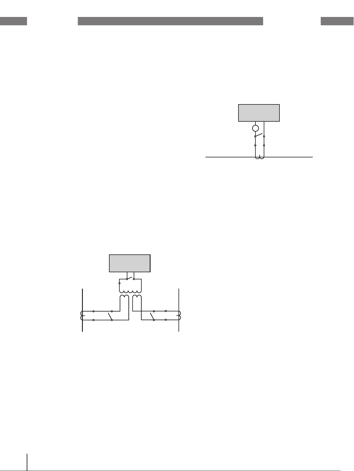
7. 6. 1 Ammeter
If you wish to measure the current not only
with the UMG but rather with an ammeter
too, connect the ammeter to the UMG
in series.
UMG
I
S2
1
S
A
Einspeisung
Supply
(k)S
1 S2(l)
2(L)(K)P1
P
Fig. Circuit diagram with additional ammeter switched
in series
Verbraucher
Consumer
UMG
I
S
S2
1
Einspeisung 1
Supply 1
1P1
(K)
(L)
1P2
Verbraucher A
Consumer A
1S1
1S
P1
1S1 1S2 2S1 2S2
(k)
(l)
2
P2
Einspeisung 2
Supply 2
2S1
(k)
(l)
2S2
Verbraucher B
Consumer B
2P
2P2
1
(K)
(L)
Fig. Example for current measurement via a total current
transformer
21
Page 27

www.janitza.com UMG 509-PRO
L1
L2
L3
N
V
1 V2 V3 V4 Vref
3p 4wu
L1
L2
L3
N
3p 4w
L1
L2
L3
N
3p 4w
I1 I2 I3 I4
S1 S2 S1 S2 S1 S2 S1 S2
L1
L2
L3
N
V
1 V2 V3 V4 Vref
3p 4wu
L1
L2
L3
N
V
1 V2 V3 V4 Vref
3p 4w
L1
L2
V
1 V2 V3 V4 Vref
1p 2w
L1
L2
L3
3p 2i0
L1
L2
L3
N
3p 4w
L1
L2
L3
N
V
1 V2 V3 V4 Vref
3p 4wu
L1
L2
L3
3p 2i0
I1 I2 I3 I4
S1 S2 S1 S2 S1 S2 S1 S2
L1
L2
L3
N
3p 4w
I1 I2 I3 I4
S1 S2 S1 S2 S1 S2 S1 S2
L1
L2
L3
N
V
1 V2 V3 V4 Vref
3p 4wu
L1
L2
L3
N
V
1 V2 V3 V4 Vref
3p 4w
L1
L2
V
1 V2 V3 V4 Vref
1p 2w
L1
L2
L3
3p 2i0
L1
L2
L3
N
3p 4w
L1
L2
L3
V
1 V2 V3 V4 Vref
3p 3wu
L
L
L
L
N
3p 5w
L
L
L
L
V
1 V2 V3 V4 Vref
3p 5w
N
L1
L2
L3
N
V
1 V2 V3 V4 Vref
3p 4wu
L1
L2
V
1 V2 V3 V4 Vref
1p 2w
L1
L2
L3
3p 2i0
I1 I2 I3 I4
S1 S2 S1 S2 S1 S2 S1 S2
L1
L2
L3
N
3p 4w
I1 I2 I3 I4
S1 S2 S1 S2 S1 S2 S1 S2
L
L
L
L
N
3p 5w
I1 I2 I3 I4
S1 S2 S1 S2 S1 S2 S1 S2
7. 7 Connection variants
7. 7. 1 Voltage measurement
L1
L1
L2
L3
L2
N
1p 2w
L1
L2
L3
3p 3w
V1 V2 V3 V4 Vref
V1 V2 V3 V4 Vref
3p 4w
Fig. Measurement in a three-phase 4-conductor network Fig. Measurement in a single-phase 2-conductor network
V1 V2 V3 V4 Vref
L1
L2
L3
3p 3wu
Fig. Measurement in a three-phase 3-conductor network
without neutral conductor
V1 V2 V3 V4 Vref
Fig. Measurement in a three-phase 3-conductor network
L1
L2
L3
Fig. Measurement in a three-phase 4-conductor network
N
3p 4wu
V1 V2 V3 V4 Vref
L
L
L
N
L
3p 5w
Fig. Measurement in a three-phase 4-conductor network
with an additional conductor
V1 V2 V3 V4 Vref
22
Page 28
UMG 509-PRO www.janitza.com
L1
L2
L3
N
3p 2i
I1 I2 I3 I4
S1 S2 S1 S2 S1 S2 S1 S2
L1
L2
L3
N
3p 2i
L1
L2
1p 2i
I1 I2 I3 I4
S1 S2 S1 S2 S1 S2 S1 S2
I1 I2 I3 I4
S1 S2 S1 S2 S1 S2 S1 S2
L1
L2
L3
N
3p 4w
I1 I2 I3 I4
S1 S2 S1 S2 S1 S2 S1 S2
L1
L2
L3
N
3p 2i
I1 I2 I3 I4
S1 S2 S1 S2 S1 S2 S1 S2
L1
L2
L3
N
3p 2i
L1
L2
L3
3p 2i0
L1
L2
1p 2i
I1 I2 I3 I4
S1 S2 S1 S2 S1 S2 S1 S2
I1 I2 I3 I4
S1 S2 S1 S2 S1 S2 S1 S2
I1 I2 I3 I4
S1 S2 S1 S2 S1 S2 S1 S2
L1
L2
L3
N
3p 4w
I1 I2 I3 I4
S1 S2 S1 S2 S1 S2 S1 S2
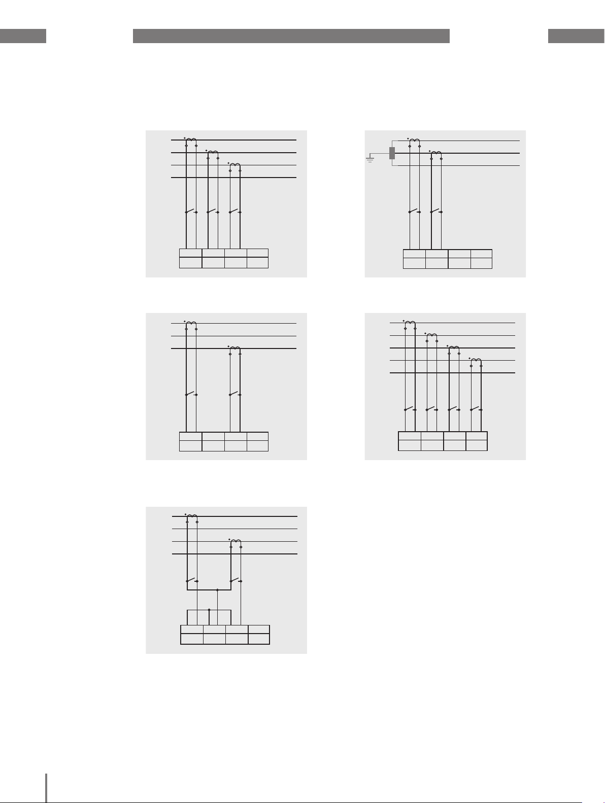
7. 7. 2 Current measurement
L1
L2
L3
N
S1 S2 S1 S2 S1 S2 S1 S2
3p 4w
Fig. Measurement in a three-phase 4-conductor network
via three current transformers
L1
I1 I2 I3 I4
L2
L3
S1 S2 S1 S2 S1 S2 S1 S2
3p 2i0
Fig. Measurement in a three-phase 3-conductor network
via two current transformers
I1 I2 I3 I4
L1
L2
S1 S2 S1 S2 S1 S2 S1 S2
1p 2i
Fig. Measurement in a single-phase 2-conductor network
via 2 current transformers
L
I1 I2 I3 I4
L
L
L
N
S1 S2 S1 S2 S1 S2 S1 S2
3p 5w
Fig. Measurement in a three-phase 4-conductor network
via four current transformers
I1 I2 I3 I4
23
L1
L2
L3
N
S1 S2 S1 S2 S1 S2 S1 S2
3p 2i
Fig. Measurement in a three-phase 4-conductor network
via two current transformers
I1 I2 I3 I4
Page 29

www.janitza.com UMG 509-PRO
L1
L2
L3
V
4 N
3w 1m
I
4
S1 S2
L1
L2
L3
N
V
4 N
4w 1m
I
4
S1 S2
L1
L2
L3
V
4 N
3w 1m
I
4
S1 S2
7. 7. 3 Supporting measurement, input V4
L1
L2
L3
N
4w 1m
Fig. Measurement in a three-phase 4-conductor
network with symmetric loading
3w 1m
V4 N
L1
L2
L3
V4 N
S1 S2
I4
S1 S2
I4
NOTE!
C
If the a baseline measurement
is connected to a three-phase
3-conductor network, the supporting
measurement can no longer be used
as a measurement input.
NOTE!
C
For measurement with the supporting
measurement, a voltage must
be connected to the baseline
measurement for frequency determination.
NOTE!
C
Measured voltages and measured
currents must derive from the same
network.
Fig. Measurement in a three-phase 3-conductor
network with symmetric loading
N
PE
2w 1n
Fig. Measurement of the voltage between N and PE.
Measurement of the current in the neutral conductor
V4 N
S1 S2
I4
24
Page 30
UMG 509-PRO www.janitza.com
7. 8 Residual current monitoring
The device:
• is suitable for use as a residual current
monitoring device (RCM) as well as for
monitoring AC, pulsing DC, and DC.
• can measure residual currents in
accordance with IEC/TR 60755 (2008-01)
of type A.
The connection of suitable external residual
current transformers with a rated current of
30 mA is performed via the residual current
transformer inputs I5 (terminals 4/5) and I6
(terminals 6/7).
7. 8. 1 Failure monitoring
The device monitors the ohmic resistance at
the residual current measurement inputs.
If this is greater than 300 Ohm, residual
current monitoring fails. This can occur due
to a cable break for example
For further information on failure monitoring,
see section “12. 7 Failure monitoring (RCM)”.
PE
Fig. “Residual current monitoring via current trans-
formers” connection variant
NOTE!
C
The transformation ratios for the
residual current transformer inputs
can be configured via the GridVis®
software. (see www.janitza.com)
NOTE!
C
It is not necessary to configure a connection schematic for measurement
inputs I5 and I6!
L2 L3N L1
Load
25
m
CAUTION!
Insufficient insulation of the operating equipment on the analogue inputs (temperature
measurement and residual current monitoring) to the mains supply circuits can cause
hazardous voltages on these inputs.
Ensure that there is reinforced or double
insulation to the mains supply circuits!
Risk of injury due to
high voltage
Page 31

www.janitza.com UMG 509-PRO
7. 8. 2 Example: Residual current transformer insulation
A residual current transformer should measure on isolated mains cables within a 300 V
CAT III network.
The insulation of the mains cables and the
insulation of the residual current transformer
must fulfil the basic insulation requirements
for 300 V CAT III. This equates to a test
voltage of 1500 V AC (duration 1 min.) for the
insulated mains cables and a test voltage of
1500 V AC (duration 1 min.) for the residual
current transformer.
L1
L2
L3
PEN
N
PE
m
CAUTION!
Transmission errors and
damage to property due to
electrical faults
If the line is longer than 30 m, there is an
increased probability of transmission errors
and damage to the device due to atmospheric discharge.
Use a shielded cable for connection to
the residual current transformer.
Residual current transformer
Residual
current
transformer
I6
L1 L2 L3 N I1 I2 I3
UMG 509-PRO
Fig. Example of a UMG 509-PRO with residual current monitoring via measuring inputs I5/I6.
c
WARNING!
Risk of injury due
to electric voltage!
I5
I4
M
3~
The Profibus, RS485, temperature measurement input and residual current monitoring
input are not galvanically separated from
each other.
Therefore, be aware that hazardous voltages on these inputs may have effects on
the other connections.
26
Page 32

UMG 509-PRO www.janitza.com
7. 9 Temperature measurement
The device has a temperature measurement
input that is designed for a maximum total
burden of 4 kOhm (sensor and cable).
The temperature is measured here via terminals 8 to 10.
PT100
Fig. Connection example for temperature measurement
with a PT100
7. 9. 1 Example: Temperature sensor
insulation
A temperature sensor in close proximity to
non-insulated mains cables should measure
within a 300 V CAT III network.
The temperature sensor must be equipped
with reinforced or double insulation for 300 V
Cat III.
VCC
PT100
10
9
8
GND
UMG 509-PRO
Fig. Schematic illustration of the connection example
m
CAUTION!
If the line is longer than 30 m, there is an
increased probability of transmission errors
and damage to the device due to atmospheric discharge.
Use a shielded cable to connect to the
temperature sensor.
c
WARNING!
The Profibus, RS485, temperature measurement input and residual current monitoring
input are not galvanically separated from
each other.
Therefore, be aware that hazardous voltages on these inputs may have effects on
the other connections.
Transmission errors and
damage to property due to
electrical faults
Risk of injury due
to electric voltage!
m
CAUTION!
Insufficient insulation of the operating equipment on the analogue inputs (temperature
measurement and residual current monitoring) to the mains supply circuits can cause
hazardous voltages on these inputs.
Ensure that there is reinforced or double
insulation to the mains supply circuits!
Damage to property due to
short circuit
27
Page 33

www.janitza.com UMG 509-PRO
28
Page 34

UMG 509-PRO www.janitza.de
8. Interfaces
The device has four interfaces that can
be used to connect it to other devices:
• RS485
• Profibus
• Ethernet
8. 1 Shielding
A twisted, shielded cable should be used
for connections via the interfaces. Note
the following when shielding:
• Earth the shields of all cables that lead
to the cabinet and at the cabinet entry.
• Connect the screens over a generous area
and in a manner that will conduct well,
to a low-noise earth.
• Gather the cables mechanically above
the earthing clamp in order to avoid
damage due to cable movements.
• Use suitable cable glands to feed
the cables into the cabinet, for example,
armoured conduit couplings.
Cable
Strain relief
Screen braid of the cable
Earthing clamp
Noiseless ground
Fig. Shielding procedure at cabinet entry.
m
CAUTION!
Atmospheric discharge can cause
transmission errors and hazardous voltages
on the device.
Therefore, note the following:
• Connect the shielding to at least one
functional earth (PE).
• If there are more significant sources
of interference, connect the shield
to the functional earth (PE) as close
as possible to the device.
• Adhere to the maximum cable length
of 12000 m at a baud rate of 38.4 K.
• Use shielded cables.
• Lay the interface lines with a spatial
separation or with additional insulation
to live system parts.
Transmission errors
and risk of injury due
to electrical faults
29
Page 35

www.janitza.de UMG 509-PRO
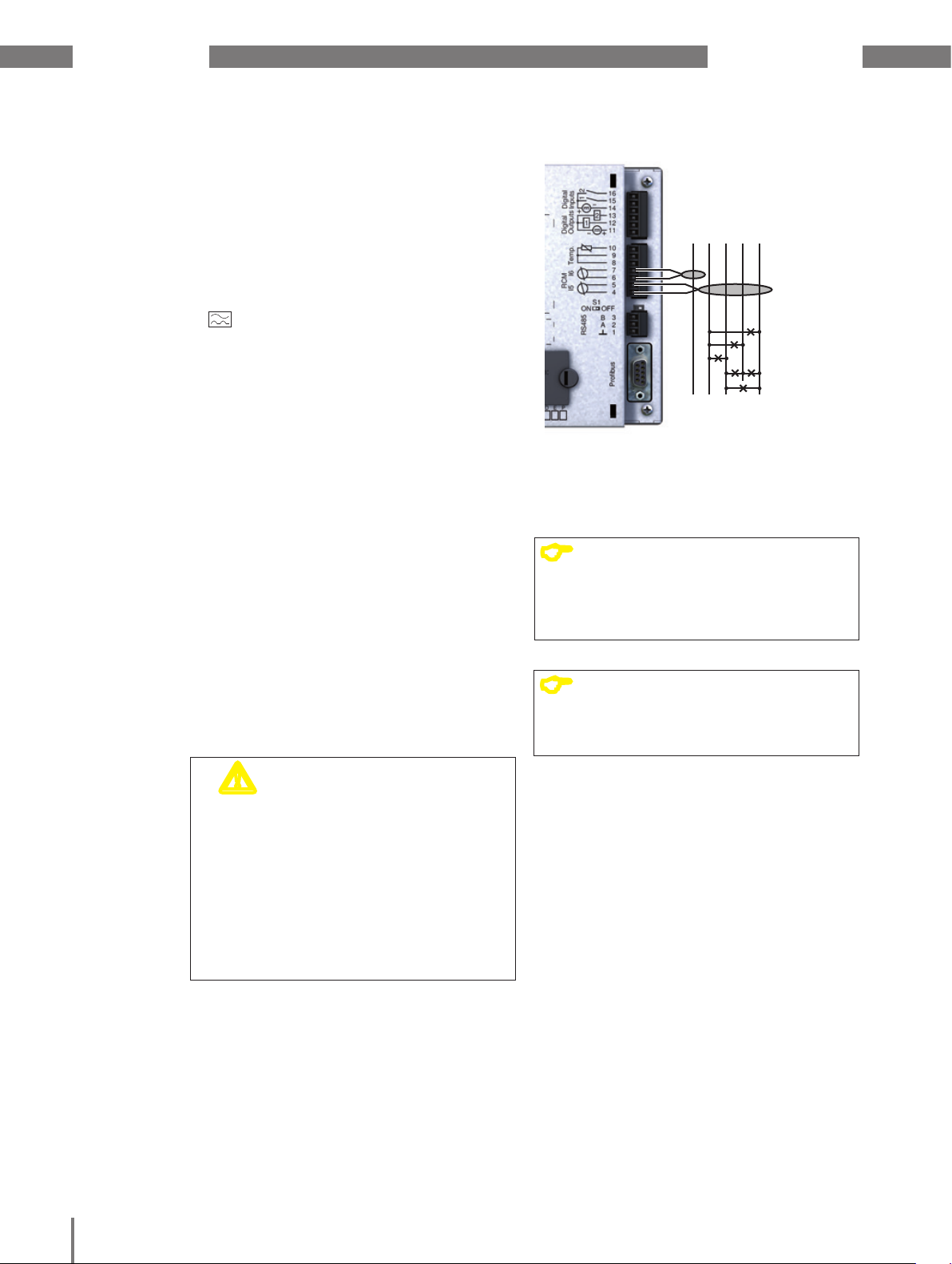
8. 2 RS485 interface
The RS485 interface on this device
is designed as a 3-pin plug contact and
communicates via the Modbus RTU protocol.
The cables used must be suitable for an
environmental temperature of at least 80 °C.
Recommended cable type:
• Unitronic Li2YCY(TP) 2x2x0.22 (from Lapp
Kabel)
B
A
8. 2. 1 Termination resistors
The cable is terminated with resistors (120
Ohm 1/4 W) at the beginning and at the end
of a segment.
Termination within the device is possible
via the S1 DIP switch on the device.
Correct
Incorrect
Terminal strip in the cabinet.
Device with RS485 interface.
(without termination resistor)
RS485 bus
GND data
Fig. RS485 connection example
c
WARNING!
Risk of injury due
to electric voltage!
The Profibus, RS485 and the temperature
measurement input are not galvanically
separated from each other.
Therefore, be aware that hazardous
voltages on these inputs may have
effects on the other connections.
Device with RS485 interface.
(with termination resistor on the device)
ON
OFF
S1
Fig. Termination via DIP switch activated (ON)
30
Page 36

UMG 509-PRO www.janitza.de
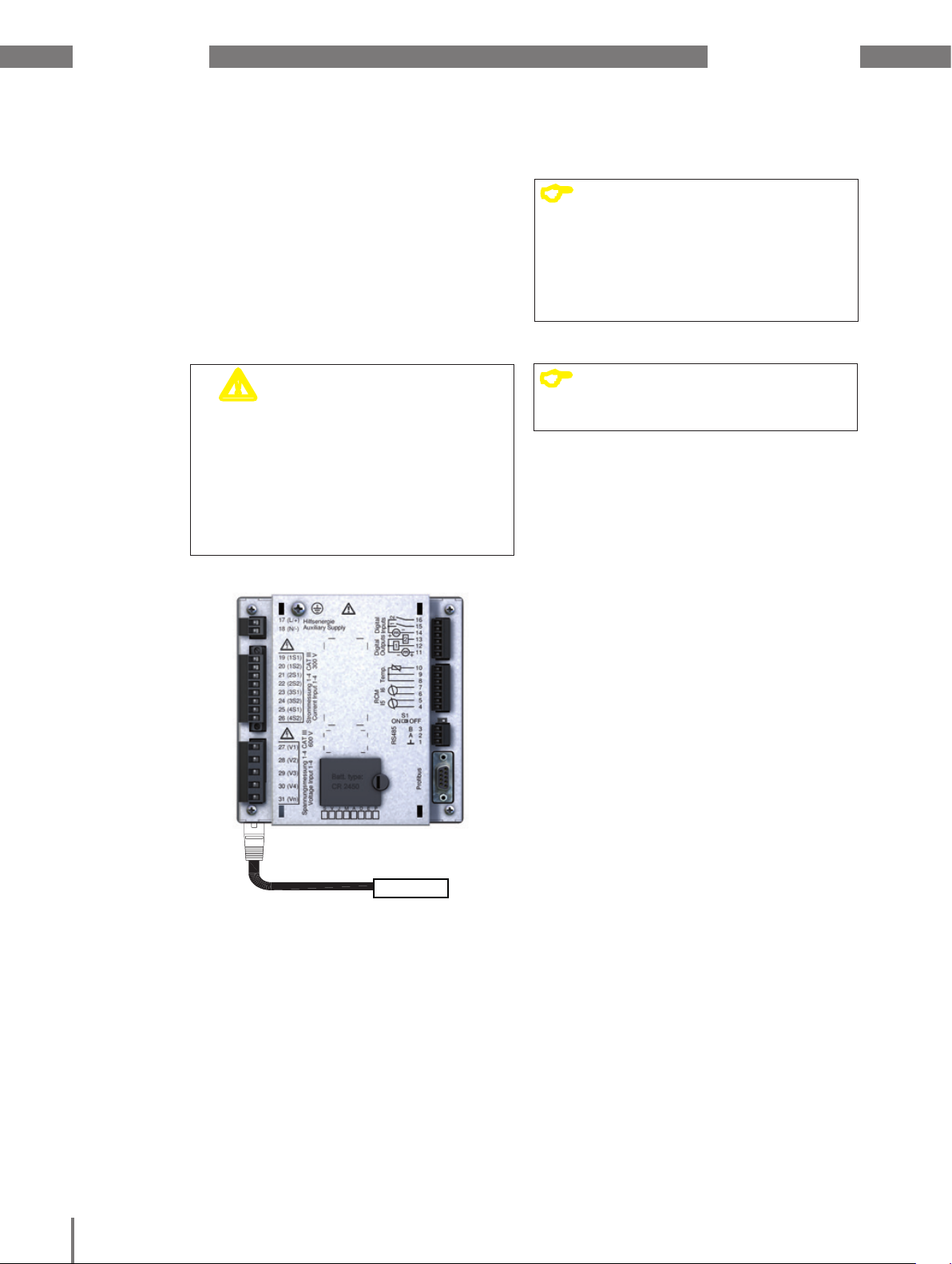
8. 3 Profibus interface
This 9-pin D-sub receptacle RS485 interface
supports the Profibus DP V0 slave protocol.
For a simple connection of inbound
and outbound bus wiring, connect
it to the device via a Profibus plug.
For the connection, we recommend a 9-pin
Profibus connector, e.g. type "SUBCONPlus-ProfiB/AX/SC" from Phoenix, item
number 2744380. (Janitza item no: 13.10.539)
D-sub
receptacle for
Profibus
Fig. Rear view UMG 509-PRO with D-sub receptacle for
Profibus
8. 3. 1 Connecting the bus lines
1. Connect the inbound bus line to terminals
1A and 1B on the Profibus connector.
2. Connect the continuing bus wiring
for the next device in line to terminals 2A
and 2B.
3. If there are no subsequent devices
in the line, terminate the bus line with
resistors by moving the switch on
the Profibus connector to ON.
UMG 509-PRO
Profibus
D-Sub,
9 pin,
socket
Fig. Profibus connector with termination resistors
Transmission
speeds in Kbit/s
9.6, 19.2, 45.45,
Profibus connector (external)
D-Sub,
9 pin,
connector
Terminating resistors
Screw-type terminals
max.
segment length
1200 m
Other
profibus
stations
93.75
187.5 1000 m
500 400 m
1,500 200 m
3000, 6000, 12000 100 m
Table Segment lengths per Profibus specification.
31
NOTE!
C
When using the device in a Profibus
system, define the device address
using the configuration menu
as described in “11. 2. 2 Field bus”!
c
WARNING!
Risk of injury due
to electric voltage!
The Profibus, RS485 and the temperature
measurement input are not galvanically
separated from each other.
Therefore, be aware that hazardous
voltages on these inputs may have
effects on the other connections.
Page 37

www.janitza.de UMG 509-PRO
8. 4 Bus structure
• All devices are connected in a bus
structure (line).
• Each device has its own address
within the bus (also see „11. 8 Profibus
Konfiguration“).
• Up to 32 participants can be connected
together in a single segment.
• The cable is terminated with resistors
(bus terminator, 120 Ohm, 1/4 W) at
the beginning and at the end of a segment.
• If there are more than 32 participants,
repeaters (amplifiers) must be used
to connect the individual segments.
• Devices for which the bus connection
is switched on must be under current.
• It is recommended that the master
be placed at the end of a segment.
• If the master is replaced with a bus
connection, the bus must be switched off.
• Replacing a slave with a bus connection
that is either switched off or de-energised
can destabilise the bus.
• Devices that are not connected
to the bus can be replaced without
destabilising the bus.
Master
T
Slave
T
Slave Slave Slave Slave
Fig. Bus structure illustration
NOTE!
C
CAT cables are not suitable for bus
wiring. Use the recommended cable
types for this.
SlaveSlaveSlave
Speisung notwendig / power supply necessary
Busabschluß eingeschaltet / bus terminator onT
Slave Slave Repeater
T
T
32
Page 38
UMG 509-PRO www.janitza.de
8. 5 Ethernet interface
The Ethernet interface is on the bottom
of the device. When connecting, ensure
that you provide a sufficient connection
area depending on the bending radius for
the Ethernet cable.
This connection area must not be smaller
than 50 mm.
m
CAUTION!
Incorrect network settings can cause faults
in the IT network.
Before connecting the device, obtain
information from your network
administrator about the correct settings
for your device.
Damage to property due to
incorrect network settings
NOTE!
C
The device is factory-set to dynamic
IP address allocation (DHCP mode).
You can change these settings as
described in “11. 2. 1 Ethernet(TCP/
IP)” or using the GridVis® software.
NOTE!
C
We recommend using at least CAT5
cables for connection.
33
Ethernet connection
Patch cable
Fig. Rear view of UMG 509-PRO with patch cable
PC/switch
Page 39

www.janitza.de UMG 509-PRO
34
Page 40
UMG 509-PRO www.janitza.de
9. Digital inputs and outputs
9. 1 Digital inputs
The device has two digital inputs.
An input signal is detected on a digital input if
a voltage of at least 18 V and maximum 28 V
DC (typically at 4 mA) is applied.
There is no input signal for a voltage of 0
to 5 V and a current less than 0.5 mA.
+
-
m
CAUTION!
Transmission errors
and damage to property
due to electrical faults
If the line is longer than 30 m, there
is an increased probability of transmission
errors and damage to the device due
to atmospheric discharge.
Use a shielded cable for connection
to the digital inputs.
UMG 509-PRO
Digital inputs 1-2
2k21
2k21
2k21
2k21
2k21
External
Auxiliary voltage
14
15
Digital
Input 1
Digital
Input 2
S1
16
S2
24V DC
-
+
Fig. Connection of digital inputs
NOTE!
C
Pay attention to the supply voltage's
polarity.
Fig. Example for connecting external contacts S1 and S2
to digital inputs 1 and 2
35
Page 41

www.janitza.de UMG 509-PRO
9. 1. 1 S0 pulse input
You can connect an S0 pulse transducer per
DIN EN62053-31 to any digital input.
This requires an external auxilliary voltage
with an output voltage in the range 18 to 28 V
DC and a resistor of 1.5 kOhm.
External
1.5 kOhm
transducer
24 V DC
-
S0 pulse
UMG 509-PRO
Digital inputs 1-2
2k21
2k21
2k21
2k21
2k21
Auxiliary voltage
14
15
Digital
Input 1
16
Digital
Input 2
Fig. Example for connecting an S0 pulse transducer
to digital input 1
+
36
Page 42

UMG 509-PRO www.janitza.de
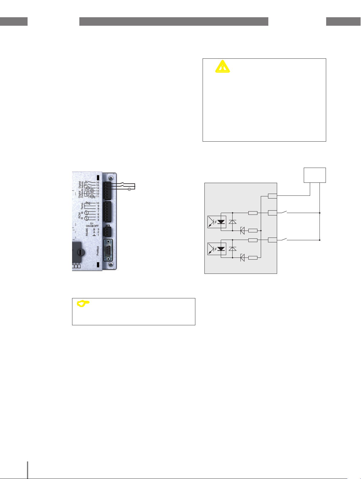
9. 2 Digital outputs
The device has two digital outputs, which:
• are galvanically separated from
the analysis electronics using opto
couplers.
• have a joint consumption.
• can switch DC loads.
• require an external auxiliary voltage.
• can be used as pulse outputs.
~
C
CAUTION!
When using the digital outputs as pulse
outputs, measurement errors may arise due
to the residual ripple.
Therefore, use a mains adapter for
the supply voltage for the digital inputs
and outputs, which has a residual ripple
of less than 5% of the supply voltage.
CAUTION!
The digital outputs are not short-circuit
proof! Connection errors can therefore
cause damage to the connections.
Ensure that the wiring is correct when
connecting the outputs.
NOTE!
You can use the GridVis® software
to set functions for the digital
outputs clearly.
(see www.janitza.de)
m
m
Measurement errors when
using as a pulse output
Damage to property due
to connection errors
Fig. Connection of digital outputs
UMG 509-PRO
Digital outputs 1-2
Fig. Example for connecting 2 relays to digital outputs 1 and 2
Digital Ouput 1
Digital Ouput 2
11
12
13
External
Auxiliary voltage
24V DC
+
DC
K1
DC
K2
-
37
Page 43

www.janitza.de UMG 509-PRO
38
Page 44
UMG 509-PRO www.janitza.de
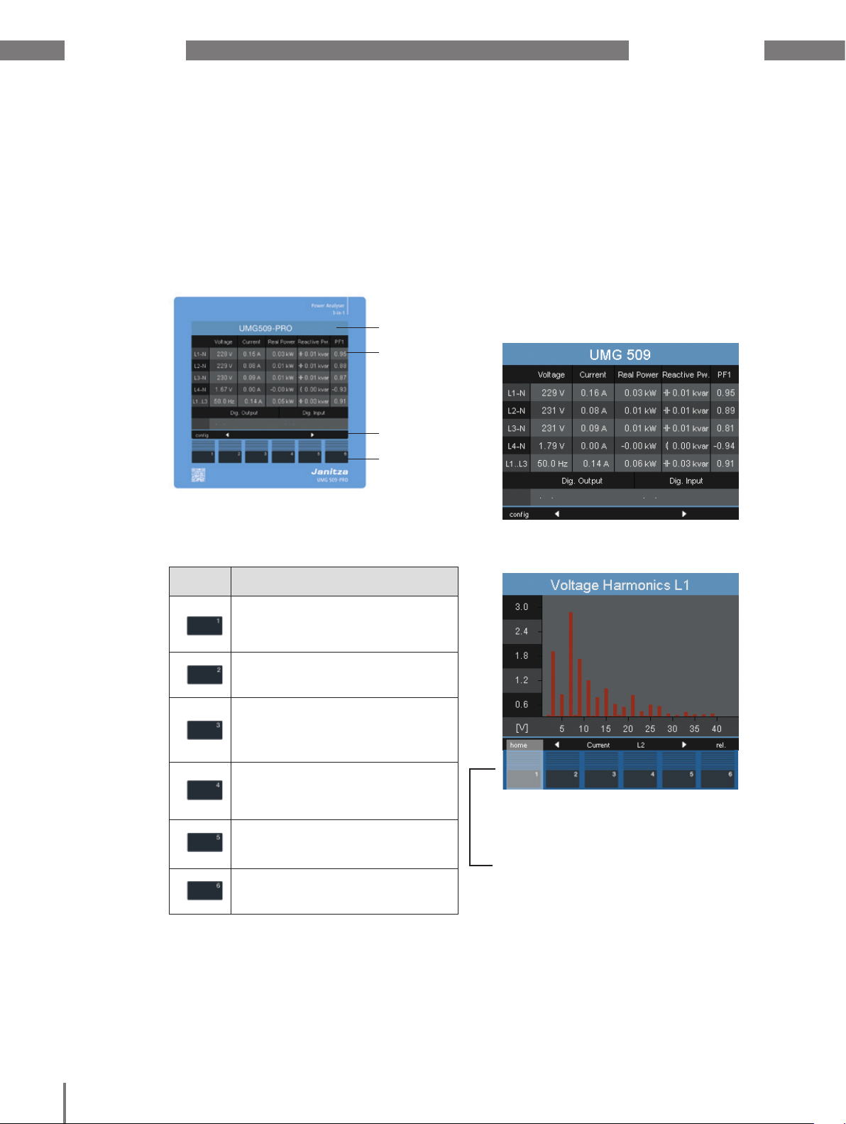
10. Operation
The device is operated via six function keys
that have different functional assignments
depending on the context:
• selecting measured value indications.
• Navigation within the menus.
• Editing device settings.
Display title
Measured
values
Labelling of
the Function keys
Function keys
Fig. UMG 509-PRO "Home" measured value indication
10. 1 Button allocation
10. 2 “Home" measured value indication
After the power returns, the device starts with
the "Home" measured value indication.
This measured value indication contains
the device names and an overview
of important measured values. In its
delivery condition, the unit name consists
of the device type and the serial number
of the device.
Fig. UMG 509-PRO "Home" measured value indication
Button
Function
• Returns to the first screen
(home)
• Exits selection menu
• Selects number
• Selects main values (U, I, P ...)
• Changes (number -1)
• By-values (select)
• Selects menu item
• Changes (number +1)
• By-values (select)
• Selects menu item
• Selects number
• Selects main values (U, I, P ...)
• Opens selection menu
• Confirm selection
Fig. UMG 509-PRO Harmonics of voltage L1
Using the "Home - button 1", you
navigate directly to the first "Home"
measured value indication from
the measured value indications
for the main values
39
Page 45
www.janitza.de UMG 509-PRO
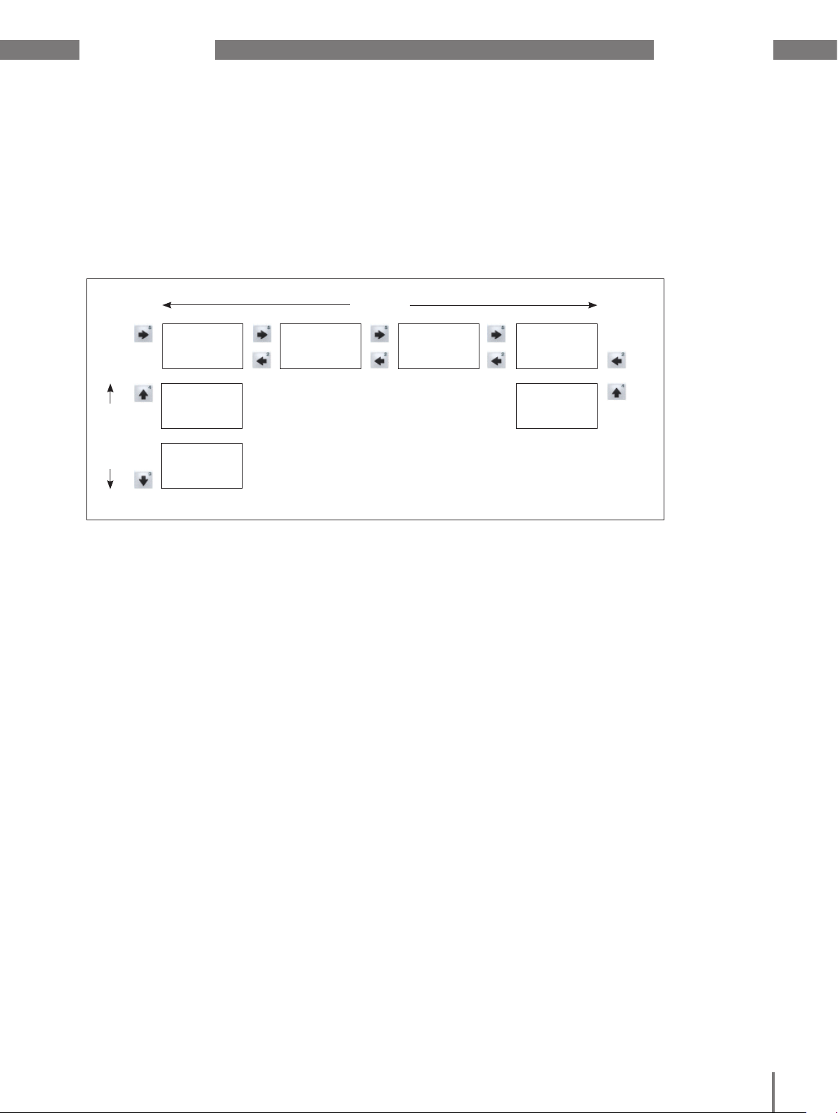
10. 3 Measured value indication
10. 3. 1 Main values
Using buttons 2 and 5, you can scroll
between the main values of the measured
value indications. You can find an overview
of the main values in section “17. 2 Overview
of measured value indications”.
10. 3. 2 By-values
Using buttons 3 and 4, you can select
the by-values of a measured value indication.
These are also provided in section “17. 2
Overview of measured value indications”.
Main values
...
By-values
Display
Oscilloscope L1
Display
Oscilloscope L2
Display
Oscilloscope L3
Display
Communication
Status
Display
Home
Display
Voltage L-N
Display
Voltage L-L
...
40
Page 46
UMG 509-PRO www.janitza.de
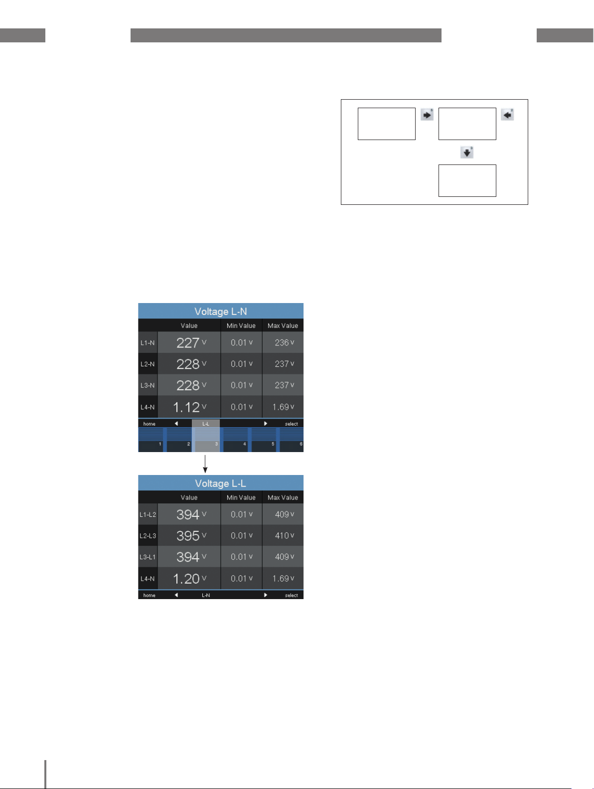
10. 4 Selecting a measured value indication
In order to switch to a measured value
indication with main values, use function keys
2 to 5 to select the required measured value
indications with main values.
Using the 1 (home) function key, you always
navigate to the first measured value indication.
Proceed as follows to switch to a measured
value indication with by-values:
1. Select the measured value indication with
the main values.
2. Use function keys 3 and 4 to select
the measured value indication
for the required by-values.
Display
Home
... ...
Fig. Example: Selecting the voltage by-values.
Display
Voltage L-N
Display
Voltage L-L
41
Fig. Selecting a measured value indication
Page 47
www.janitza.de UMG 509-PRO
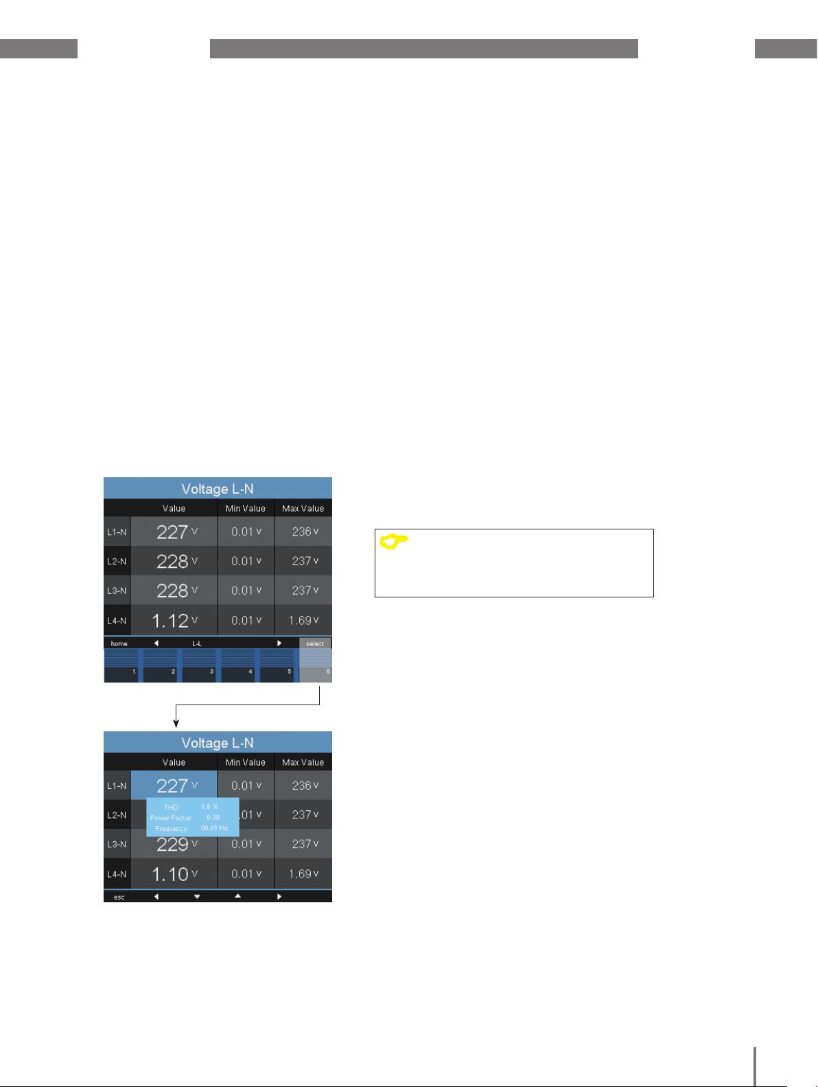
10. 5 View additional information
Proceed as follows to view additional
information such as the power factor
and frequency:
1. Use buttons 2 to 5 to scroll to the desired
measured value indication.
2. Activate the measured value selection
using the 6 key (select).
• The background colour for the measured
value switches from grey to blue.
The additional information is displayed
in an additional window.
3. Use buttons 2 and 5 to select the desired
measured value.
4. End the procedure using the button 1
(ESC) or select another measured value
using buttons 2 to 5.
10. 6 Deleting values
Proceed as follows to delete individual
minimum and maximum values:
1. Use buttons 2 to 5 to scroll to the desired
measured value indication.
2. Activate the measured value selection
using the 6 key (select).
• The background colour for the measured
value switches from grey to blue.
The additional information is displayed
in an additional window.
3. Use buttons 2 to 5 to select the desired
minimum or maximum value.
• The time along with the date and time
of the occurrence are displayed as
additional information.
4. Using the 6 key (reset), you can delete
the selected minimum or maximum value.
5. End the procedure using button 1 (ESC)
or select another minimum or maximum
value with buttons 2 to 5.
NOTE!
C
The date and time for the minimum/
maximum values are specified
displayed in UTC.
Fig. Additional information for L1-N voltage
42
Page 48

UMG 509-PRO www.janitza.de
10. 7 Transients list
Transient voltages:
• are fast impulse transient effects
in electrical networks.
• are unpredictable from a time perspective
and have a limited duration.
• are caused by lightning strikes, switching
operations or by tripped fuses.
A total of 16 detected transients are listed
in the 2-page transients list for the device.
Proceed as follows to display a specific
transient voltage:
1. Use buttons 2 and 5 to scroll
to the "Transients" main value display
2. Select the desired page using button 4.
3. Use button 6 (selection) to access
the transients list.
• The background colour for the date/time
switches from grey to blue.
4. Press button 3 or 4 to select a transient.
5. Use button 6 (select) to display
a transient graphically.
6. Press button 6 (key) again to show or hide
the key.
7. You can exit the transient graph display
using button 1 (ESC).
Fig. Displaying a transient
43
Page 49

www.janitza.de UMG 509-PRO
10. 8 Event list
Events are threshold value violations
of effective current and voltage values.
A total of 16 detected events are listed
in the two-page event list for the device.
Proceed as follows to display a specific
event:
1. Use buttons 2 and 5 to scroll to
the "Events" main value display.
2. Select the desired page using button 4.
3. Use button 6 (selection) to access event
list.
• The background colour for the date/time
switches from grey to blue.
4. Press button 3 or 4 to select an event.
5. Use button 6 (select) to display an event
graphically.
6. Press button 6 (key) again to show or hide
the key.
7. You can exit the event’s graphical display
using button 1 (ESC).
Fig. Displaying an event
44
Page 50

UMG 509-PRO www.janitza.de
11. Configuration
The supply voltage must be connected
to configure the device. Proceed as
described in “12. 1 Connecting the supply
voltage”.
To call the configuration menu, press button
1 on the “Home” measured value indication.
11. 1 Languages
You can set the language for the measured
value indications and menus directly
in the configuration menu.
There are different languages available
for selection. The factory default setting
for the language is "English".
Proceed as follows to change the system
language:
1. Open the configuration menu.
2. Press button 3 or 4 until the language field
has a blue background.
3. Press button 6 (enter) to open
the language selection.
4. Press button 3 or 4 to select the desired
language.
5. Press button 6 (enter) again to confirm
your selection.
11. 2 Communication
You can configure the Ethernet
and RS485 interface for your device
in the communication menu.
Proceed as follows to access
the communication menu:
1. Open the configuration menu. Press button
1 in the “Home menu”.
2. Press button 3 or 4 until
the communication field has a blue
background.
3. Press button 6 to open
the “Communication” menu.
11. 2. 1 Ethernet(TCP/IP)
Select the mode for address allocation and,
if necessary, the IP address, subnet mask
and the gateway in this section. The latter
is allocated automatically in the BOOTP
and DHCP allocation modes.
The device has three types of address
allocation:
• Off - You define the IP address, subnet
mask and gateway, and set them directly
on the device. Select this mode for
straightforward networks without DHCP
servers.
45
• BOOTP - - BootP enables the fully
automatic integration of a UMG 509-PRO
into an existing network. However, BootP
is an older protocol and does not provide
the scope of functions provided by DHCP.
• DHCP - When started, the device
automatically obtains the IP address,
the subnet mask and the gateway from
a DHCP server. DHCP is factory-set.
Fig. "Configuration" menu
Page 51
www.janitza.de UMG 509-PRO
Proceed as follows to adjust the IP address,
subnet mask and gateway:
1. Press button 3 or 4 until the relevant field
has a blue background.
2. Press button 6 to activate the input.
• The font changes to red and a cursor
is displayed.
3. Now press button 3 or 4 to select
the required digit.
4. Use button 5 to move to the next digit.
5. Repeat steps 3 and 4 until you have
completed the required input.
6. Press button 6 to confirm your input.
m
CAUTION!
Incorrect network settings can cause faults
in the IT network.
Obtain information from your network
administrator about the correct settings
for your device.
Damage to property due
to incorrect network settings
11. 2. 2 Field bus
If you connect the device via the RS-485
interface, configure the following settings
in this section:
• Modbus protocol - Here, you can select
whether the device works as a slave or a
master/gateway within the bus structure.
• Device address - Here, you can select
a device address that is used to address
the device in the bus. This address must
be between 0 and 255, and be unique
in the tree structure.
• Baud rate - Select the same baud
rate for all devices in a bus structure.
Possible settings are 9600, 19200, 38400,
57600,115200, 921600 kbps. The factory
default setting is 115200 kbps.
Proceed as follows to make the adjustments:
1. Press button 3 or 4 until the relevant field
has a blue background.
2. Press button 6 (enter) to call the selection
options.
3. Press button 3 or 4 to select the required
value.
4. Press button 6 to confirm your selection.
46
Page 52

UMG 509-PRO www.janitza.de
11. 3 Measurement
You can configure the following
in the measurement menu:
• the measuring transducer for current
and voltage measurement.
• recording transients.
• recording events.
• the mains frequency.
• the temperature sensor.
The device has:
• 4 measurement channels for current
measurement (I1 - I4)
• 4 measurement channels for voltage
measurement (V1 - V4 against Vref).
Measured voltage and measured current for
the measurement channels 1-4 must derive
from the same network.
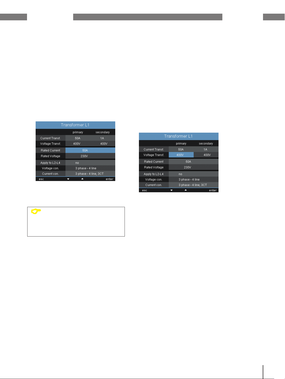
11. 3. 1 Measuring transducer
You can make the following adjustments for
baseline and supporting measurements here:
• current transformer
• voltage transformer
• rated current
• rated voltage
• connection
As well as settings for transformation ratios
and monitoring for the residual current
transformer.
Current transformer
You can assign current transformer
ratios to the baseline measurement and
the supporting measurement.
Select the 5/5 A setting when measuring
currents directly.
Setting range:
Primary 1 to 999999
Secondary 1 to 5
Fig. Measurement configuration
Factory default setting:
Primary 5
Secondary 5
Fig. Configuring current transformer ratios
47
Page 53
www.janitza.de UMG 509-PRO
Rated current
The rated current defines the reference point
for:
• overcurrent
• current transients
• automatic scaling of graphics
Setting range:
0 0 to 999999 A
Fig. Configuring the rated current
Voltage transformer
You can assign voltage transformer
ratios to the baseline measurement
and the supporting measurement.
Select the 400/400 V setting when measuring
without a voltage transformer.
Setting range:
Primary 1 to 999999 V
Secondary 1 to 999 V
Factory default setting:
Primary 400 V
Secondary 400 V
C
Fig. Voltage transformer configuration
NOTE!
You can set the nominal value
for measuring the K-factor and TDD
via the GridVis® software.
(see www.janitza.de)
48
Page 54

UMG 509-PRO www.janitza.de
Rated voltage
The rated voltage defines the reference point
for:
• transients,
• events
• automatic scaling of graphics
Setting range: 0 to 1000000 V
Factory default setting: 230 V
You can also select the primary voltage
as the rated voltage.
Transfer L2 - L4
These settings can be adjusted for each
phase.
You can use the “Transfer L2 - L4” menu
item to transfer the settings from phase L1
to phases L2, L3 and L4, in order to prevent
having to enter everything again.
• No - The settings from phase L1 will not
be transferred to phases L1 to L4.
• Yes - The settings from phase L1 will be
transferred to phases L1 to L4.
Fig. Configuring the rated voltage
Fig. Transferring settings to L2 - L4
Fig. “Transfer setting “deactivated.
49
Page 55

www.janitza.de UMG 509-PRO
Voltage measurement connection schematic
The following connection schematics can
be selected for voltage measurement:
3p4w 3 phases, 4 conductors
3p4wu 3 phases, 4 conductors
3p3w 3 phases, 3 conductors
For networks without a neutral
conductor and with symmetrical loading
3p3wu 3 phases, 3 conductors
For networks without a neutral
conductor and with symmetrical loading
3p5w 3 phases, 4 conductors
Measurement on an additional
conductor
1p2w 1 phase, 2 conductors (180°)
Factory default setting: 3p4w
NOTE!
C
It is not necessary to configure
a connection schematic
for measurement inputs V4 and I4.
Current measurement connection schematic
The following connection schematics can
be selected for the current measurement:
3p4w 3 phases, 4 conductors, 3 current
transformers
3p5w 3 phases, 4 conductors, 4 current
transformers
The fourth current transformer can be
used for the measurement in the neutral
conductor.
3p2i 3 phases, 4 conductors, 2 current
transformers
For networks with symmetrical loading.
3p2i0 3 phases, 3 conductors, 2 current
transformers
Aron circuit for networks without a
neutral conductor. The third current is
calculated
1p2i 1 phase, 2 conductors, 2 current trans-
formers
Factory default setting: 3p4w
Fig. Configuration of voltage connection schematic
Fig. Voltage measurement connection schematic
Fig. Configuration of current connection schematic
Fig. Current measurement connection schematic
50
Page 56

UMG 509-PRO www.janitza.de
Residual current transformer
When using residual current inputs I5 and
I6, the corresponding transformer ratios
of the used residual current transformer must
be set.
Setting range:
Primary 1 to 1000000
Secondary 1
Factory default setting:
Primary 127
Secondary 1
You can also use this menu to adjust failure
monitoring for the corresponding residual
current inputs:
• Activated - Switches on failure monitoring
for residual current monitoring.
• Deactivated - Switches off failure
monitoring for residual current monitoring.
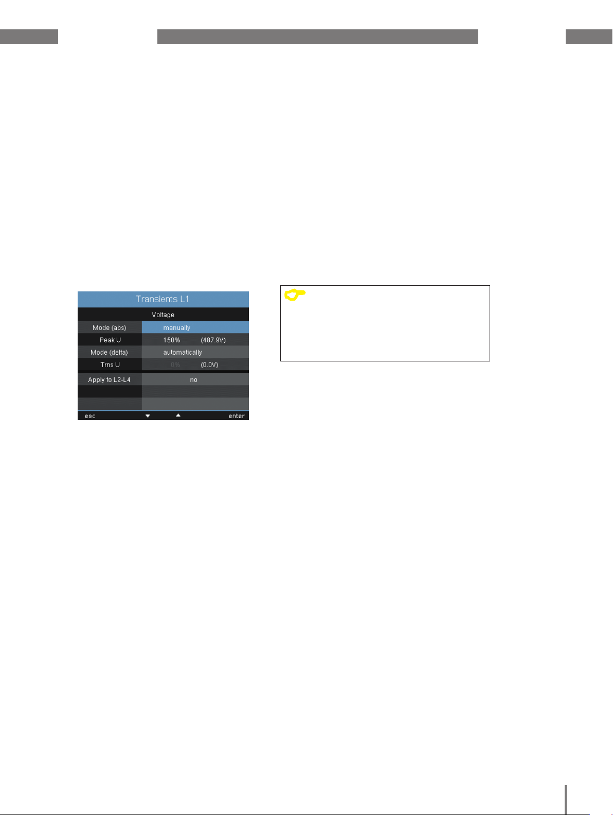
11. 3. 2 Transients
The device:
• monitors the voltage measurement inputs
for transients.
• detects transients that are longer than
50µs.
• can detect transients according to two
different criteria.
• can receive different monitoring settings
for each phase.
If a transient has been detected:
• the wave form is saved to a transient
record.
• the threshold value increases by 20 V
for the next 10 minutes, both in automatic
and in manual mode.
• it will be recorded with 509 points
for a period of 60 seconds per additional
transient.
You can use the GridVis® event browser
to display recorded transients.
Fig. Residual current transformer configuration
Fig. Configuring monitoring for residual current
monitoring
The following modes are available
for recording the transients:
• absolute
• delta
Fig. Configuring transients
51
Page 57
www.janitza.de UMG 509-PRO
Mode (absolute)
If a sample value exceeds the set threshold
value, a transient is detected:
• Off - Transient monitoring has been
switched off
• Automatic - Factory default setting.
The threshold value is calculated
automatically and is 110% of the current
200 ms effective value.
• Manual - Transient monitoring uses
the configurable threshold values under
"Peak".
Transfer L2-L4
Transient monitoring can be adjusted for
each phase. You can adopt these settings
from phase L1 and apply them to phases L2,
L3 and L4.
• No - The settings from phase L1 will not
be transferred to phases L2, L3 and L4.
• Yes - The settings from phase L1 will
be transferred to phases L2, L3 and L4.
NOTE!
C
In order to determine the mains
frequency automatically, a voltage
L1-N of greater than 10 Veff must
be applied to voltage measurement
input V1.
Fig. Configuring transient recording mode
Mode (delta)
If the difference between two neighbouring
sample points exceeds the set threshold
value, a transient is detected:
• Off - Transient monitoring has been
switched off.
• Automatic - Factory default setting.
The threshold value is calculated
automatically and is 0.2175 times
the current 200 ms effective value.
• Manual - Transient monitoring uses
the configurable threshold values under
"Trns U".
52
Page 58

UMG 509-PRO www.janitza.de
11. 3. 3 Events
Events are threshold value violations of set
threshold values for current and voltage.
Here, threshold values are compared with
the full wave effective values for current
and voltage from the measurement channels.
The event record contains the following:
Limit value
violations
before the
lead time
Start time event
(Trigger time)
Event record
Pre-run
After-run
NOTE!
C
You can use the GridVis® software
to set an event record.
(see www.janitza.de)
NOTE!
C
You can only set the pre-run
and after-run using the GridVis®
software. (see www.janitza.de)
Factory default setting: 0
• a mean value
• a min. and max. value
• a start and end time.
Event
Follow-up timeLead time
Limit value violations
before the follow-up time
Measured
value
Vollwelleneffektivwert
Limit value
End time
Fig. Shows the full wave effective values
for an event.
An event is triggered if there is an
uninterrupted threshold value violation within
the pre-run time. The event is ended if there
is no threshold value violation within the afterrun time.
You can set threshold values and hysteresis
as a percentage of the rated value. Threshold
values can be set for
• overvoltage and undervoltage,
• overcurrent.
If an event has occurred, the corresponding
measured value is recorded with the set
pre-run and after-run periods (0 to 1000 full
waves).
53
An event describes faults due to:
• overvoltage/undervoltage
• overcurrent
• overfrequency/underfrequency
• rapid frequency changes
Monitoring of the threshold values can
be switched off (Off/Manual).
Page 59

www.janitza.de UMG 509-PRO
Voltage dip
A voltage dip is set in % of the rated voltage.
Fig. Configuration of event recording for
voltage dips
Overvoltage
The overvoltage is set in % of the rated
voltage.
Overcurrent
The rapid increase of current is set in %
of the nominal current.
11. 3. 4 Mains frequency
The device requires the mains frequency
to measure and calculate measured values.
The device is suitable for measurements
in networks with a mains frequency
is in the range of 40 Hz to 70 Hz.
The mains frequency can be stipulated
by the user or automatically determined
by the device.
• Auto - Factory default setting. The mains
frequency will be measured.
• 50 Hz - The mains frequency is fixed
at 50 Hz. The mains frequency will not
be measured.
• 60 Hz - The mains frequency is fixed
at 60 Hz. The mains frequency will not
be measured.
Transfer L2-L4
The events monitor can be adjusted for each
phase. You can adopt these settings from
phase L1 and apply them to phases L2, L3
and L4.
• No - The settings from phase L1 will not
be transferred to phases L2, L3 and L4.
• Yes - The settings from phase L1 will
be transferred to phases L2, L3 and L4.
Fig. Setting the network nominal frequency
Automatic frequency determination
In order for the device to determine
the frequency automatically, at least
a voltage (V-Vref) of greater than 10 Veff must
be applied to at least one of the voltage
measurement inputs.
If there is no sufficiently high measured
voltage available, the device cannot
determine the mains frequency and therefore
cannot perform any measurements.
54
Page 60
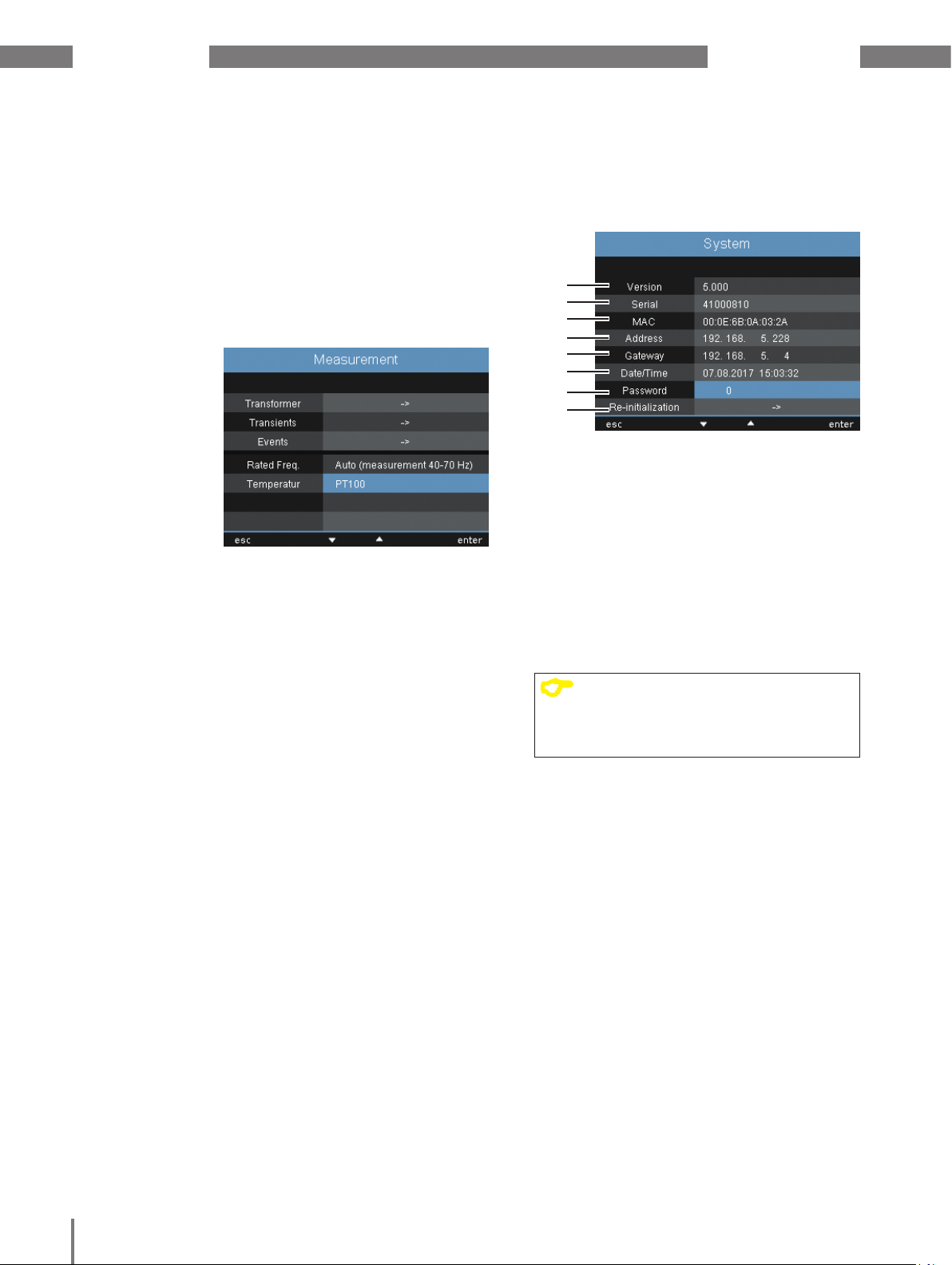
UMG 509-PRO www.janitza.de
11. 4. 2 Temperature
When using a temperature measurement,
select the corresponding sensor type from
a predefined list:
• PT100
• PT1000
• KTY83
• KTY84
Fig. Selecting the temperature sensor
11. 4 System
You can call system settings and change
them as far as possible here.
1
2
3
4
5
6
7
8
Fig. System settings
1 Firmware version
2 Device serial number
3 Fixed MAC address of the device
4 Set IP address
5 Set gateway address
6 Date and time
7 Set password
8 Reset settings
NOTE!
C
You can use the GridVis® software
to make the settings for time
synchronisation, date and time.
55
Page 61
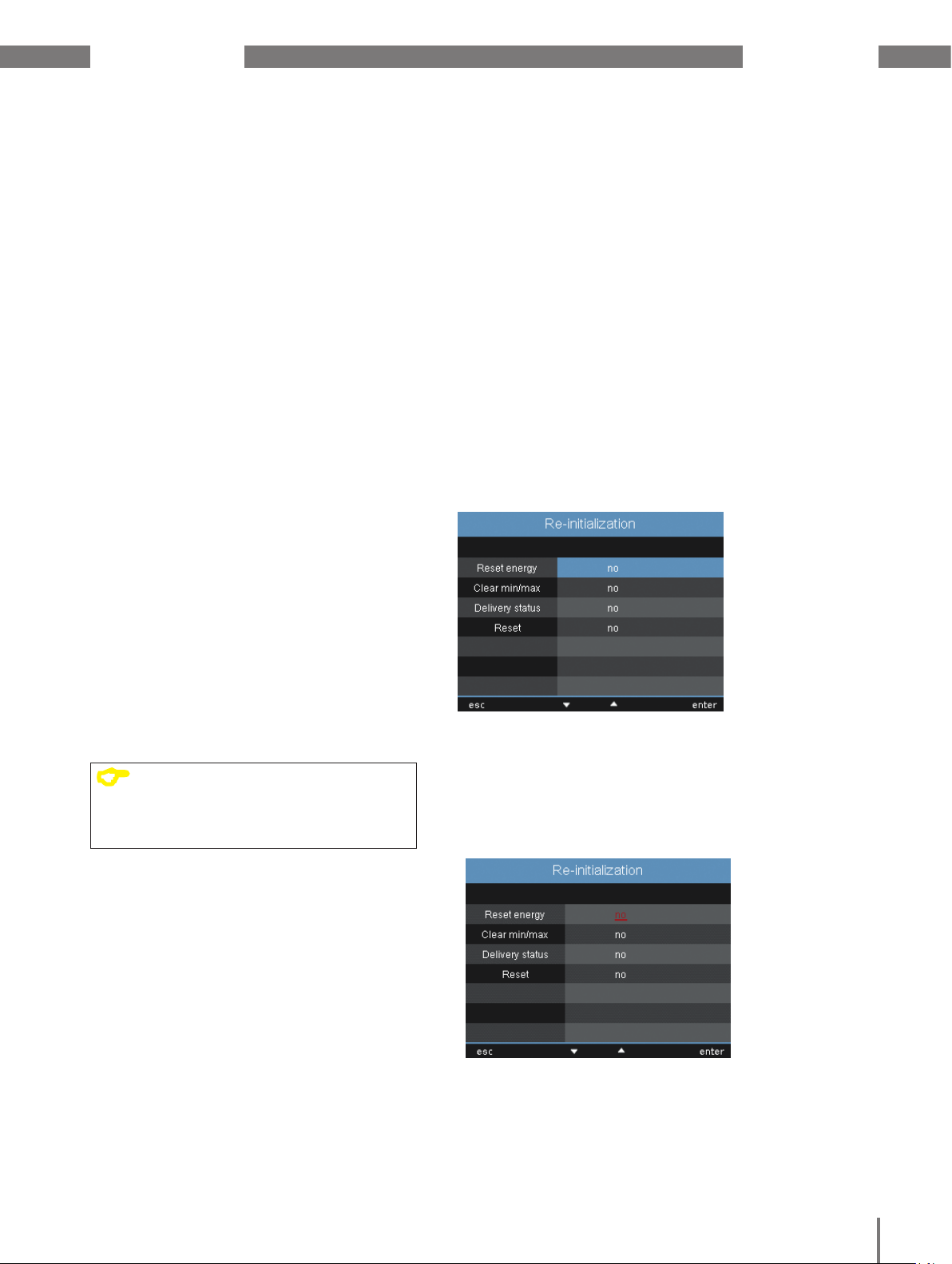
www.janitza.de UMG 509-PRO
11. 4. 1 Password
The user can block access
to the configuration with a password.
The configuration can then only be
changed directly on the device by entering
the password.
The password consists of a 6-digit code.
Setting range:
1-999999 = With password
0 = no password
A password (0) is not factory-set.
To change a password that has already been
set, you must know the current password.
Note down the changed password.
Proceed as follows to set a password:
1. Open the system menu
2. Use button 3 or 4 to navigate
to the password setting.
3. Press button 6 to open the output.
4. Now press button 2 or 5 to enter
the required button.
5. Press button 6 again to confirm your input.
• If you no longer want a password prompt,
enter the password "0".
NOTE!
C
If you no longer remember your
password, you can only change
it using the GridVis® software.
11. 4. 3 Reset
You can reset the settings to the factory
settings in this area.
Resetting the energy
You can clear all energy meters in the device
at the same time. Specific energy meters
cannot be selected.
1. Open the reset menu.
2. Use button 3 or 4 to select the “Reset
energy” item (highlighted in green)
3. Press button 6 to activate the input.
• The font colour changes to red and a
cursor is displayed.
4. Change the value by pressing button 4
on “Yes”.
5. Press button 6 to confirm your input.
• The "Carried out" message appears
in the line, all energy meters have been
cleared.
Fig. Resetting the energy
56
Page 62

UMG 509-PRO www.janitza.de
Deleting min. / max. values
You can clear all min. and max. values
in the device at the same time.
For information on how to clear individual
min. and max. values, see “10. 6 Deleting
values”.
1. Open the reset menu.
2. Use button 3 or 4 to select the “Min./max.
values” item (highlighted in green)
3. Press button 6 to activate the input.
• The font colour changes to red and a
cursor is displayed.
4. Change the value by pressing button 4 on
“Yes”.
5. Press button 6 to confirm your input.
• The "Carried out" message appears in the
line, all min. and max. values have been
cleared.
Fig. Deleting min. / max. values
Delivery status
You can reset all settings such as
the configuration and the recorded data
to the factory default setting here. Entered
activation codes are not deleted.
1. Open the reset menu.
2. Use button 3 or 4 to select the “Delivery
status” item (highlighted in green)
3. Press button 6 to activate the input.
• The font colour changes to red and a
cursor is displayed.
4. Change the value by pressing button
4 on “Yes”.
5. Press button 6 to confirm your input.
• The "Carried out" message appears
in the line, the delivery status is restored.
Re-initialisation
Proceed as follows to re-initialise the device
manually:
1. Open the reset menu.
2. Use button 3 or 4 to select the “Reinitialise” item (highlighted in green)
3. Press button 6 to activate the input.
• The font colour changes to red and
a cursor is displayed.
4. Change the value by pressing button
4 on “Yes”.
5. Press button 6 to confirm your input.
• The device re-initialises within approx.
10 seconds.
57
NOTE!
C
Before commissioning, clear
any content that may be present
on the power meters due
to the production process
Page 63

www.janitza.de UMG 509-PRO
11. 5 Display
You can adjust your device’s display settings
here
Brightness
You can adjust your device’s display
brightness here. Proceed as described
in the template in the previous chapter.
Setting range: 0 to 100%
Factory default setting: 100%
• 0% = dark
• 100% = very bright
NOTE!
C
The service life of the backlight
is extended if the brightness
of the backlight is lower.
Standby
Here, you can set the time after which
the display brightness switches to the set
standby brightness.
Screen Saver
You can activate or deactivate the screen
saver here.
NOTE!
C
If the same screen is shown on
the display for an extended period,
this can cause damage to the display.
Using the screen saver prevents
this and therefore extends
the display’s service life.
Setting range: Yes, no
Factory default setting: Yes
Display
Here, you can define the speed at
which the new measured values appear
in the measured value indications.
Setting range:
fast, slow (200ms), slow (1 sec.)
Factory default setting: Fast
Setting range: 60 to 9999 sec.
Factory default setting: 900 sec.
Brightness (standby)
Here, you can set the display brightness
that the system switches to after the
standby time has elapsed. The standby time
is restarted using buttons 1-6.
Setting range: 0 to 60%
Factory default setting: 40%
Rotate
You can activate or deactivate the automatic
changeover between the different measured
value indications here.
Setting range: Yes, no
Factory default setting: No
Rotation interval
Here, you can set the time after which
the screen automatically switches
to the next measured value indication.
Setting range: 0 to 255 seconds
Factory default setting: 0 seconds
58
Page 64

UMG 509-PRO www.janitza.de
11. 6 Colours
You can select the colours for displaying
the current and voltage in the graphic
representations here.
1. Press button 3 or 4 until the colour field
has a green background
2. Press button 6 to open the colours menu
3. Press button 3 or 4 to select the required
colour field.
4. Press button 6 to confirm your selection
5. Press button 3 or 4 to select the required
colour.
6. Press button 6 to confirm your selection.
To activate the function, enter the 6-digit
activation code in the corresponding line.
Make sure that the activation code is only
valid for one device.
Fig. Menu setting for extensions
Jasic status
Up to 7 customer-specific Jasic programs
(1-7) and a recording can run in the device.
The Jasic programs can have the following
statuses:
Fig. Menu setting for colours
11. 7 Extensions
Here, you can:
• activate functions that are subject
to charge.
• call the status of the Jasic programs.
Activation
The device contains the following functions
that are subject to charge, which you
can activate subsequently:
• BACnet
You receive the activation codes from
the manufacturer. The manufacturer requires
the serial number of the device and the name
of the function to be activated.
• Stopped
• Running
NOTE!
C
You can change the status
of the Jasic programs using
the software.
Fig. Menu setting for Jasic status
59
Page 65

www.janitza.de UMG 509-PRO
60
Page 66

UMG 509-PRO www.janitza.de
12. Commissioning
This section provides you with all
the information you require to commission
your device for the first time.
12. 1 Connecting the supply voltage
Proceed as follows when setting
up the supply voltage:
1. Connect the supply voltage to the rear
of the device using a terminal.
2. After connecting the supply voltage,
the first measured value indication, Home,
appears on the display.
3. If no display appears, check whether
the supply voltage is within the rated
voltage range.
m
CAUTION!
Failure to observe the connection conditions
can damage or destroy your device.
Therefore, note the following:
• Adhere to the specifications for voltage
and frequency on the rating plate.
• Do not use the device to measure DC
voltage.
Damage to property
due to not observing
the connection conditions
12. 2 Connecting the measured voltage
Proceed as follows when connecting
measured voltage:
1. Connect the measured voltage to the rear
of the device using a terminal.
2. After connecting the measured voltage,
the measured values displayed
by the device for the L-N and L-L
voltages must correspond to those
on the measurement input.
3. Pay attention to any voltage transformer
factors that are set.
c
WARNING!
If the device is subjected to surge voltages
higher than the overvoltage category,
safety-relevant insulations in the device
can be damaged, which means
that the product’s safety can no longer
be guaranteed.
Only use the device in environments
in which the permissible overvoltage
category is not exceeded.
Risk of injury due
to electric voltage!
61
Page 67

www.janitza.de UMG 509-PRO
12. 3 Frequency measurement
To measure, the device requires mains
frequency that can either be specified
by the user or determined automatically
by the device.
• In order to determine the frequency
automatically, at least a voltage (V-Vref)
of greater than 10 Veff must be applied
to at least one of the voltage measurement
inputs.
• The mains frequency must be in the range
from 40 Hz to 70 Hz.
• If there is no sufficiently high measured
voltage available, the device cannot
determine the mains frequency
and therefore cannot perform any
measurements.
12. 4 Phase sequence
Check the direction of the rotating field
voltage in the measured value indication
of the device.
A “right-hand” rotation field usually exists.
UL1-UL2-UL3 = right rotation field
UL1-UL3-UL2 = left rotation field
Fig. Indication of the phase sequence according
to the direction of the rotating field.
62
Page 68

UMG 509-PRO www.janitza.de
12. 5 Applying the measured current
The device:
• is intended for connecting current
transformers with secondary currents
of ../1 A and ../5 A.
• does not measure DC.
• has current measurement inputs that are
loaded with 120 A for 1 second.
The factory-set current transformer ratio
is 5/5 A and must be adapted to the current
transformer employed if necessary.
Proceed as follows when connecting
the measured voltage:
Fig. Phasor diagram
Voltage (shown with a long
phasor)
1. Short circuit all current transformer outputs
except for one.
2. Connect the measured voltage via
the terminals on the back of the device
and affix it sufficiently with two screws.
3. Compare the current displayed
on the device with the current input.
• The currents must match based
on the current transformer conversion
ratio.
• The device must display approx. zero
amperes in the short circuited current
measurement inputs.
Phase shift angle sign prefix (U/I):
• positive (+) for capacitive load
• negative (-) for inductive load
C
Current (shown with a short
phasor)
NOTE!
Voltages and currents that are
outside the permissible metering
range can damage the device.
63
Page 69

www.janitza.de UMG 509-PRO
12. 5. 1 Phasor diagram examples
The following are two examples for
an indication of measured current and
measured voltage in the phasor diagram:
Example 1
Predominantly ohmic load.
Voltage and current only
have a minor deviation
in the phase length.
• The current measurement input is assigned
to the correct voltage measurement input
Example 2
Predominantly ohmic load.
Voltage and current have
a deviation of about 180°
in the phase position.
• The measurement input is assigned
to the correct voltage measurement input.
• In the current measurement considered
here, the k and l connections are reversed
or there is a return feed in the mains power
supply.
12. 6 Applying the residual current
Only connect residual current transformers
with a rated current of 30 mA to inputs
I5 and I6!
Both residual current inputs can measure
AC currents, pulsing direct currents and
DC currents.
Bearing in mind the current transformer ratio,
the residual current displayed by the device
must correspond to the current input.
The current transformer ratio is factory-set to
127/1 A and must be adapted to the residual
current transformer used if necessary.
NOTE!
C
It is not necessary to configure
a connection schematic for
measurement inputs I5 and I6!
NOTE!
C
The device requires the mains
frequency to measure the residual
currents. Establish a measured
voltage for this or set a fixed
frequency.
64
Page 70

UMG 509-PRO www.janitza.de
12. 7 Failure monitoring (RCM)
The device enables continuous monitoring
of the connection to the residual current
transformer on inputs I5 and I6.
You can activate failure monitoring via:
• the relevant menu item as described in
section “11. 3. 1 Measuring transducer”.
• or by setting address 18895 for residual
current measurement input I5 and 18897
for I6.
If there is an interruption in the connection to
the current transformer, this state is recorded
in certain registers or indicated in the
GridVis® software.
12. 7. 1 Alarm status
Using bit-by-bit coding inside the alarm
register (addr. 19224 for I5, 19225 for I6),
it is possible to read out different alarm
statuses:
Example:
Bit:
14 1312 11 10 9 8
0150 0 0 0 0 0 0
Unused
Alarm
Overcurrent
Warning
Fig. Alarm register
6 5 4 3 2 1 0
070 0 0 0 0 0 0
Overcurrent was measured. The alarm
bit is also set and must be acknowledged!
Bit:
14 1312 11 10 9 8
0150 0 0 0 0 0 0
6 5 4 3 2 1 0
070 0 0 0 1 1 0
Modbus addr. Value / Function (int32)
18895 (I5)
18897 (I6)
Failure monitoring for I5 / I6
0 = Deactivate monitoring
1 = Activate monitoring
Modbus addr. Value / Function (short16)
18907 (I5)
18908 (I6)
0 = Connection of
the residual current
transformer to I5 and I6
error-free
1 = Error in the current
transformer connection to I5
and I6
Unused
Alarm
Overcurrent
Warning
Fig. Example of alarm register if overcurrent is
measured.
Warning: The residual current has
exceeded the set warning limit
value
Overcurrent:
The measurement range has
been exceeded
Alarm: Alarm bit is set for: Warning
or overcurrent.
The alarm bit must be reset
or acknowledged manually.
65
Page 71

www.janitza.de UMG 509-PRO
12. 8 Measurement range exceeded
If the measurement range is exceeded,
it is displayed as long as this persists and
cannot be acknowledged. The measurement
range is exceeded if at least one of the four
voltage or current measurement inputs lies
outside their specified measuring range.
Threshold values for exceeding
the measurement range (200 ms effective
values):
Fig. In the Phasor diagram, the voltages are displayed
I = 7.5 Amps
UL-N = 600 Vrms
with long phasors and the currents with short
phasors.
12. 10 Checking the communication
The device counts all received (RX), all
transmitted (TX) and all faulty data packages.
Fig. Indication of values exceeding the measurement
range in voltage circuit L2 and in current path I4
12. 9 Checking the power measurement
1. Short circuit all current transformer outputs
except for one.
2. Check the powers displayed.
• The device may only display one power
output in the phase with a non-shortcircuited current transformer input.
• If this is not the case, check the
connection of the measured voltage and
the measuring-circuit current.
If the active power amount is correct but the
sign of the power output is negative, this
could have two possible causes:
Ideally, the number of errors displayed
in the error column is zero.
You can reset the counter for the data
packages to 0 by pressing button 6. The start
time for the new counting process is reset
automatically.
Fig. Communication status
1. S1(k) and S2(l) are reversed at the current
transformer.
2. Active energy is being supplied back into
the network.
66
Page 72

UMG 509-PRO www.janitza.de
12. 11 Communication in the bus system
12. 11. 1 RS485
The MODBUS RTU protocol with CRC
check on the RS485 interface can be used
to access the data from the parameter and
the measured value lists (see “11. 2. 2 Field
bus”).
Modbus functions (master)
01 Read coil status
02 Read input status
03 Read holding registers
04 Read input registers
05 Force single coil
06 Preset single register
15 (0F Hex) Force multiple coils
16 (10Hex) Preset multiple registers
23 (17Hex) Read/write 4X registers
Modbus functions (slave)
03 Read holding registers
04 Read input registers
06 Preset single register
16 (10Hex) Preset multiple registers
23 (17Hex) Read/write 4X registers
The sequence of bytes is high before low
byte (Motorola format).
Transmission parameters
Data bits: 8
Parity: None
Stop bits (UMG 509): 2
External stop bits: 1 or 2
Designation Hex Comment
Device
address
Function 03 “Read Holding Reg”
Start address Hi4A 19000dez = 4A38hex
Start address Lo38
Ind. Hi
values
Ind. Lo
values
Error check
(CRC)
The "Response" of the device can appear as
follows:
Designation Hex Comment
Device
address
Function 03
Byte meter 06
Data 00 00hex=00dez
Data E6 E6hex=230dez
Error check
(CRC)
The L1-N voltage read by address 19000 is
230 V.
01 Address=1
00 2dez = 0002hex
02
-
01 Address=1
-
67
Number formats
short 16 bit (-215 to 215 -1)
float 32 bit (IEEE 754)
Example: Reading the L1-N voltage
The L1-N voltage is saved in the measured
value list at address 19000. The L1-N voltage
is available in FLOAT format.
The device address is 01 in this example.
The Query Message appears as follows:
C
C
NOTE!
Broadcast (address 0) is
not supported by the device.
NOTE!
The message length must
not exceed 256 bytes.
Page 73

www.janitza.de UMG 509-PRO
12. 11. 2 Profibus
Profibus profiles
A Profibus profile contains the data
to be exchanged between a UMG and a
PLC. Four Profibus profiles are preconfigured
at the factory.
You can use the Profibus profile to:
• retrieve measured values from the UMG,
• set the digital outputs in the UMG,
• query the status of the digital inputs
in the UMG.
Each Profibus profile can hold a maximum
of 127 bytes of data. If more data has to be
transferred, simply create additional Profibus
profiles.
Every Profibus profile has a profile number.
The profile number is sent by the PLC
to the UMG.
You can use GridVis® to edit 16 Profibus
profiles (profile numbers 0 - 15) directly.
Additional Profibus profiles (profile numbers
16 to 255) can be created using Jasic
programs.
Device master file
The device master file, abbreviated as
the GSD file, describes the Profibus
characteristics of the UMG. The GSD file
is required by the configuration program
of the PLC.
The device master file for your device
has the file name "U5090F15.GSD" and
is available on the Janitza homepage.
Variable definition
All system variables and global variables1) can
be individually scaled and converted into one
of the following formats:
• 8, 16, 32 bit integer with and without sign.
• 32 or 64 bit float format.
• Big endian = High byte before low byte.
• Little endian = Low byte before high byte.
1)
Global variables are defined by the user in Jasic and are available to each
interface in the device.
Factory pre-configured Profibus profiles
cannot be subsequently changed.
68
Page 74

UMG 509-PRO www.janitza.de
Example: Using Profibus to retrieve
measured values
You must use the GridVis® software to define
at least one Profibus profile and transfer
this to the device.
A Jasic program is not required.
PLC
PLC process output box
1. Byte = Profile number (0 to 15)
2. Byte = Data to the UMG 509-PRO
1. Byte =
2. Byte = Data requested by UMG 509-PRO
Data
•
•
PLC process input box
Return signal from the profile number
•
•
Profibus
Profile number
Profile number
Fig. Block diagram for data exchange between PLC and UMG 509-PRO.
UMG 509-PRO
Fetch measured values
for this profile number.
Measured values
69
Page 75

www.janitza.de UMG 509-PRO
Factory pre-configured profiles
This section provides you with a tabular
overview of the pre-configured Profibus
profiles
• Profibus profile number 0
Byte
index
1 1 Voltage L1-N Float 1
2 5 Voltage L2-N Float 1
3 9 Voltage L3-N Float 1
4 13 Voltage L4-N Float 1
5 17 Voltage L2-L1 Float 1
6 21 Voltage L3-L2 Float 1
7 25 Voltage L1-L3 Float 1
8 29 Current L1 Float 1
9 33 Current L2 Float 1
10 37 Current L3 Float 1
11 41 Current L4 Float 1
12 45 Active power L1 Float 1
13 49 Active power L2 Float 1
14 53 Active power L3 Float 1
15 57 Active power L4 Float 1
16 61 Cos phi (math.) L1 Float 1
17 65 Cos phi (math.) L2 Float 1
18 69 Cos phi (math.) L3 Float 1
19 73 Cos phi (math.) L4 Float 1
20 77 Frequency Float 1
21 81 Total active power L1-L4 Float 1
22 85 Total reactive power L1-L4 Float 1
23 89 Total apparent power L1-L4 Float 1
24 93 Total cos phi (math.) L1-L4 Float 1
25 97 Total effective current L1-L4 Float 1
26 101 Total active energy L1-L4 Float 1
27 105 Ind. Total reactive energy L1-L4 Float 1
28 109 THD voltage L1 Float 1
29 113 THD voltage L2 Float 1
30 117 THD voltage L3 Float 1
Value type Value
format
Scaling
70
Page 76

UMG 509-PRO www.janitza.de
• Profibus profile number 1
Byte
index
1 1 Voltage L1-N Float 1
2 5 Voltage L2-N Float 1
3 9 Voltage L3-N Float 1
4 13 Voltage L2-L1 Float 1
5 17 Voltage L3-L2 Float 1
6 21 Voltage L1-L3 Float 1
7 25 Current L1 Float 1
8 29 Current L2 Float 1
9 33 Current L3 Float 1
10 37 Active power L1 Float 1
11 41 Active power L2 Float 1
12 45 Active power L3 Float 1
13 49 Cos phi (math.) L1 Float 1
14 53 Cos phi (math.) L2 Float 1
15 57 Cos phi (math.) L3 Float 1
16 61 Frequency Float 1
17 65 Total active power L1-L3 Float 1
18 69 Total reactive power L1-L3 Float 1
19 73 Total apparent power L1-L3 Float 1
20 77 Total cos phi (math.) L1-L3 Float 1
21 81 Total effective current L1-L3 Float 1
22 85 Total active energy L1-L3 Float 1
23 89 Ind. Total reactive energy L1-L3 Float 1
24 93 THD voltage L1 Float 1
25 97 THD voltage L2 Float 1
26 101 THD voltage L3 Float 1
27 105 THD current L1 Float 1
28 109 THD current L2 Float 1
29 113 THD current L3 Float 1
Value type Value
format
Scaling
71
Page 77

www.janitza.de UMG 509-PRO
• Profibus profile number 2
Byte
index
1 1 Total active energy L1-L3 Float 1
2 5 Rel. Total active energy L1-L3 Float 1
3 9 Deliv. Total active energy L1-L3 Float 1
4 13 Total reactive energy L1-L3 Float 1
5 17 Ind. Total reactive energy L1-L3 Float 1
6 21 Total cap. reactive energy L1-L3 Float 1
7 25 Total apparent energy L1-L3 Float 1
8 29 Active energy L1 Float 1
9 33 Active energy L2 Float 1
10 37 Active energy L3 Float 1
11 41 Inductive reactive energy L1 Float 1
12 45 Inductive reactive energy L2 Float 1
13 49 Inductive reactive energy L3 Float 1
• Profibus profile number 3
Byte
index
1 1 Active power L1 Float 1
2 5 Active power L2 Float 1
3 9 Active power L3 Float 1
4 13 Total active power L1-L3 Float 1
5 17 Current L1 Float 1
6 21 Current L2 Float 1
7 25 Current L3 Float 1
8 29 Total current L1-L3 Float 1
9 33 Total active energy L1-L3 Float 1
10 37 Cos phi (math.) L1 Float 1
11 41 Cos phi (math.) L2 Float 1
12 45 Cos phi (math.) L3 Float 1
13 49 Total cos phi (math.) L1-L3 Float 1
14 53 Reactive power L1 Float 1
15 57 Reactive power L2 Float 1
16 61 Reactive power L3 Float 1
17 65 Total reactive power L1-L3 Float 1
18 69 Apparent power L1 Float 1
19 73 Apparent power L2 Float 1
20 77 Apparent power L3 Float 1
21 81 Total apparent power L1-L3 Float 1
Value type Value
format
Value type Value
format
Scaling
Scaling
72
Page 78
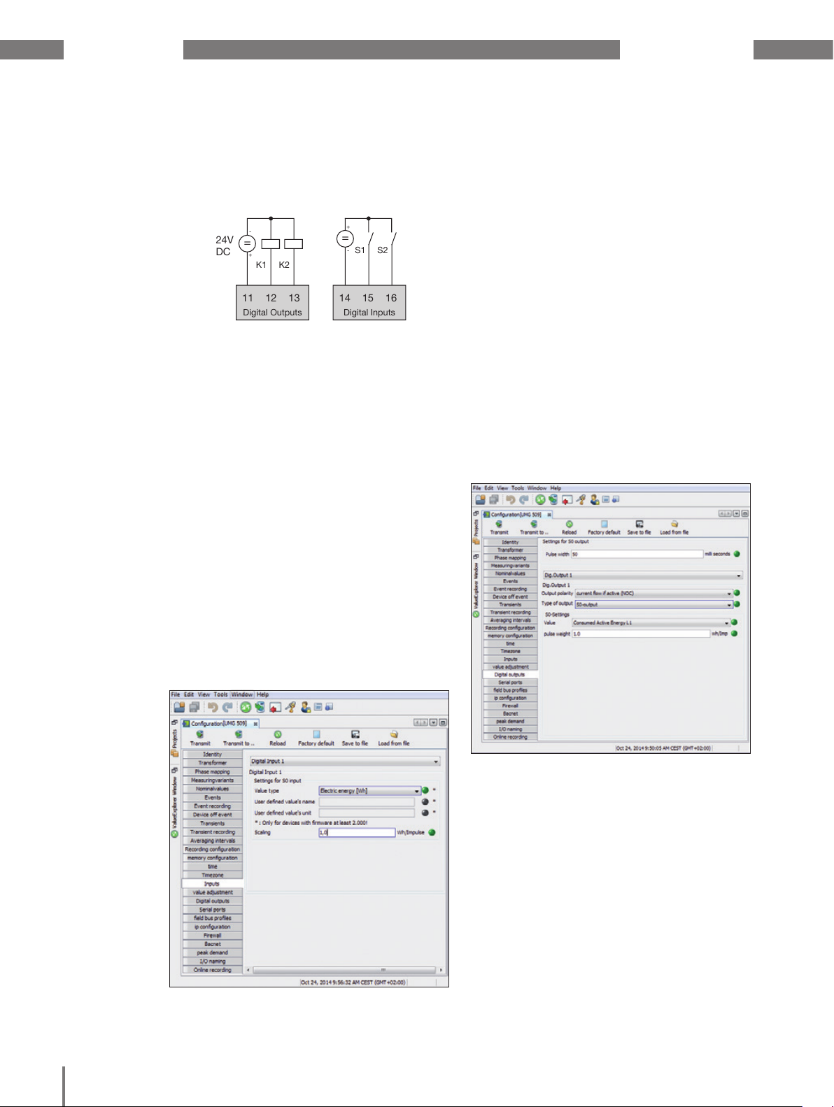
UMG 509-PRO www.janitza.de
11 12 13
24V
DC
K1 K2
=
-
+
=
+
-
S1 S2
Digital Outputs
14 15 16
Digital Inputs
12. 12 Digital inputs/outputs
Your device has two digital outputs and two
digital inputs.
Fig.: Digital outputs and inputs
The inputs and outputs can be configured
using the GridVis® software supplied as
standard.
12. 12. 1 Digital inputs
You can use the digital inputs to send
information from other devices that have
a digital output to your device directly.
You can use the configuration window
in GridVis® to define the input range for both
digital inputs:
12. 12. 2 Pulse output
The digital outputs can be used for the output
of pulses for the computation of power
consumption. For this purpose, a pulse
of defined length is applied on the output
after reaching a certain, adjustable amount
of power.
You must make various adjustments
in the configuration menu using the GridVis®
software to use a digital output as a pulse
output:
• pulse width
• digital output that is to be configured,
• output type (event notification or S0
output)
• the measured value to be transferred
• pulse value
• The value type that the incoming signal
has.
• The scaling factor that is to be used
for the value.
Fig. Configuring the UMG 509-PRO inputs via GridVis®.
Fig. Configuring the UMG 509-PRO digital outputs via
GridVis®.
73
Page 79
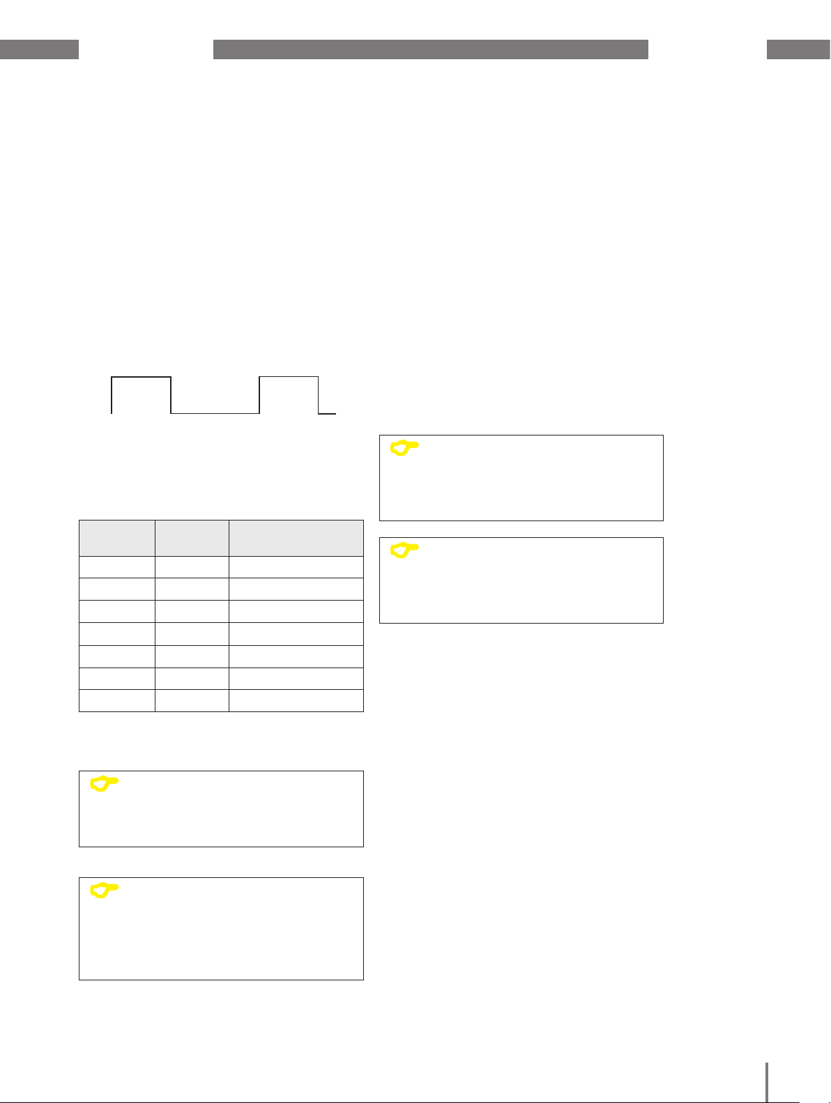
www.janitza.de UMG 509-PRO
Pulse length
The pulse length applies to both pulse
outputs and is set using the GridVis®
software.
The typical pulse length for S0 pulses
is 30ms.
Pulse interval
The pulse interval is at least as large
as the selected pulse length.
The pulse interval depends on the measured
power, for example, and can take hours
or days.
Pulse length
10ms to 10s
Fig. Schematic illustration of a digital pulse
The values in the table are based on
the minimum pulse length and the minimum
pulse interval for the maximum number
of pulses per hour.
Pulse
length
10 ms 10 ms 180 000 pulses/h
30 ms 30 ms 60 000 pulses/h
50 ms 50 ms 36 000 pulses/h
100 ms 100 ms 18 000 pulses/h
500 ms 500 ms 3600 pulses/h
1 s 1 s 1800 pulses/h
10 s 10 s 180 pulses/h
Pulse interval
>10ms
Pulse
interval
Max. pulse/h
Pulse value
The pulse value is used to indicate how much
power (Wh or varh) should correspond to
a pulse.
The pulse value is determined
bythe maximum connected load and
the maximum number of pulses per hour.
If you specify a pulse value with a:
• positive sign, the pulses will only
be emitted when the measured value
hasa positive sign.
• negative sign, the pulses will only
beemitted when the measured value
has a negative sign.
C
C
NOTE!
Since the effective energy meter
operates with a backstop, pulses
will only be generated when
drawing electricity.
NOTE!
Since the reactive energy meter
operates with a backstop, pulses
will only be generated with inductive
load applied.
Table Examples of the maximum possible number
of pulses per hour
C
C
NOTE!
The pulse interval is proportional
to the power output within
the selected settings.
NOTE!
When programming with GridVis®,
you receive a selection of work
values which are derived from
the power output values.
(see www.janitza.de)
74
Page 80

UMG 509-PRO www.janitza.de
Determine the pulse value
1. Set the pulse length in accordance with
the requirements of the connected pulse
receiver. For example, if the pulse length
is 30 ms, the device generates a maximum
number of 60000 pulses (see "maximum
number of pulses" per hour table).
2. Determine the maximum connected load.
Example:
Current transformer = 150/5 A
Voltage L-N = max. 300 V
Power per phase = 150 A x 300 V
= 45 kW
Power at 3 phases = 45 kW x 3
Max. connected load = 135 kW
3. Calculate the pulse value:
Pulse value =
max. connected load
max. number of pulses/h
[Pulse/Wh]
m
CAUTION!
Measurement errors when
using as a pulse output
When using the digital outputs as pulse
outputs, measurement errors may arise due
to the residual ripple.
Therefore, use a mains adapter
for the supply voltage for the digital
inputs and outputs, which has a residual
ripple of less than 5% of the supply
voltage.
Pulse value = 135 kW / 60000 Imp/h
Pulse value = 0.00225 pulses/kWh
Pulse value = 2.25 pulses/Wh
External
supply voltage
UMG 509-PRO
Switch and pulse outputs
11
+24V=
Digital Ouput 1
12
Digital Ouput 2
13
Fig.: Connection example for the circuit as pulse output.
230V AC
24V DC
+
Data logger
1.5k
-
75
Page 81

www.janitza.de UMG 509-PRO
76
Page 82

UMG 509-PRO www.janitza.de
13. Device homepage
Your measurement device has an integrated
web server, which has a separate homepage.
You can use this device home page to
access your measurement device from any
end device via a standard web browser. You
can access the homepage for your device
by entering the device’s PI address in a web
browser on your end device. Section “11. 7
Extensions” describes how to connect the
device to the internet.
You can do the following here without first
installing any software:
• call historical and current measured
values.
• call the power quality status in an easy
to understand illustration.
• control your device remotely.
• access installed apps.
77
Fig. Device homepage overview
Page 83

www.janitza.de UMG 509-PRO
13. 1 Measured values
You can use the “Measured values” menu item to call simple and detailed views
of the measured values, and to display individual measured values. The following menu items
are available:
• Short overview
• Detailed measured values
• Diagrams
• RCM - residual current monitoring
• Events
• Transients
13. 1. 1 Short overview
The short overview provides you with the most important measured values for each phase,
such as the current voltage values, power values and current strength.
Fig. Short overview of measured values
78
Page 84

UMG 509-PRO www.janitza.de
13. 1. 2 Detailed measured values
In the overview, you can call extensive information on the following points:
• Voltage
• Current
• Power
• Harmonic oscillations
• Energy
• Peripheral devices (digital inputs/outputs, temperature measurements)
Fig. Detailed overview of measured values
79
Page 85

www.janitza.de UMG 509-PRO
13. 1. 3 Diagrams
You can use the “Diagrams” item to access the measured values monitor. The measured
values monitor is a configurable display of current and historical measured values with
automatic scaling. In order to display a graphic of the measured values, drag the required
values from the list on the left edge of the screen into the field in the middle of the screen.
Fig. Device homepage event records
13. 1. 4 RCM - residual current monitoring
The “RCM” item shows you the current values and absolute threshold values for the RCM
channels. For more information on residual current monitoring, see chapter 7. 8 on page 25.
Fig. Device homepage RCM
80
Page 86

UMG 509-PRO www.janitza.de
13. 1. 5 Events
You can use the “Events” item to call a graphical illustration of the recorded events such as
overcurrent or undervoltage. For more information on event recording, see “11. 3. 3 Events”.
Fig. Event records
13. 1. 6 Transients
The “Transients” area provides a graphic illustration of transients within a date list. For more
information on the transients list and on transients, see chapter 10. 7 on page 43 and 11. 3.
2 on page 51.
Fig. Transients
81
Page 87

www.janitza.de UMG 509-PRO
13. 2 Power quality
The “Power quality” section (PQ) provides you with the option of calling the PQ status
in a clear way according to common standards. Here, you have access to permanent power
quality monitoring in accordance with:
• IEC 61000-2-4 in customer supply networks.
The display is based on the traffic light principle, which makes it easy to detect events that
do not meet the relevant quality requirements without in-depth knowledge.
Fig. IEC 61000-2-4 parameters with traffic-light principle
82
Page 88

UMG 509-PRO www.janitza.de
13. 3 Apps
You have the option of extending the functions on your device retrospectively by installing
additional apps.
13. 3. 1 Push Service
The push service is an example of an installable app. The push service sends measured values directly from the device to a cloud or portal solution chosen by you, such as the Janitza
Energy Portal.
Fig. Push Service
83
Page 89

www.janitza.de UMG 509-PRO
13. 4 Information
13. 4. 1 Device information
You can use the “Device information” menu item to obtain all information and settings
that you can change on the device.
13. 4. 2 Display
The “Display” item provides you with the display of your device, which corresponds to the real
display.
You can control the device remotely here by clicking the control buttons using the mouse.
Fig. Operating the UMG 509-PRO via the device homepage
13. 4. 3 Downloads
You can use the “Downloads” item to access the download area on the Janitza homepage.
You can download catalogues and operation manuals from here.
84
Page 90

UMG 509-PRO www.janitza.de
14. Service and maintenance
The device underwent various safety checks
before delivery and is marked with a seal.
If a device is open, the safety checks must
be repeated. Warranty claims will only
be accepted if the device is unopened.
14. 1 Repair and calibration
Repair work and calibration can be carried
out by the manufacturer only.
14. 2 Front film
The front film can be cleaned with a soft cloth
and standard household cleaning agent.
Do not use acids and products containing
acid for cleaning.
14. 3 Disposal
Observe the national regulations!
If necessary, dispose of individual parts
according to their properties and existing
country-specific regulations, e.g. as:
• Electronic waste
• Plastics
• Metals
or commission a certified disposal company
with scrapping.
14. 5 Device calibration
The devices are calibrated by the manufacturer
at the factory - it is not necessary to recalibrate
the device providing that the environmental
conditions are complied with.
14. 6 Calibration intervals
We recommend having the device re-calibrated
by the manufacturer or an accredited laboratory
every 5 years approximately.
14. 7 Firmware update
In order to carry out a firmware update,
connect the device to a computer via
Ethernet and access it using the GridVis®
software.
Open the firmware update wizard by clicking
“Update device” in the “Extras” menu.
Select the relevant update file and carry out
the update.
14. 4 Service
Should questions arise, which are
not described in this manual, please contact
the manufacturer directly.
We will need the following information
from you to answer any questions:
• device name (see rating plate)
• serial number (see rating plate)
• software release (see measured value
indication)
• measured voltage and supply voltage
• precise description of the error.
Fig. GridVis® software firmware update wizard
C
NOTE!
Firmware may not be updated via
the RS485 interface.
85
Page 91

www.janitza.de UMG 509-PRO
14. 8 Battery
The internal clock is fed from the supply
voltage. If the supply voltage fails
then the clock is powered by the battery.
The clock provides date and time
information, for the records, min. and max.
values and events, for example.
The life expectancy of the battery is at least
5 years with a storage temperature of +45 °C.
The typical life expectancy of the battery
is 8 to 10 years.
The battery (type CR2450 / 3V) can
be replaced by the user.
Fig. Replacing the battery using long-nose pliers
86
Page 92
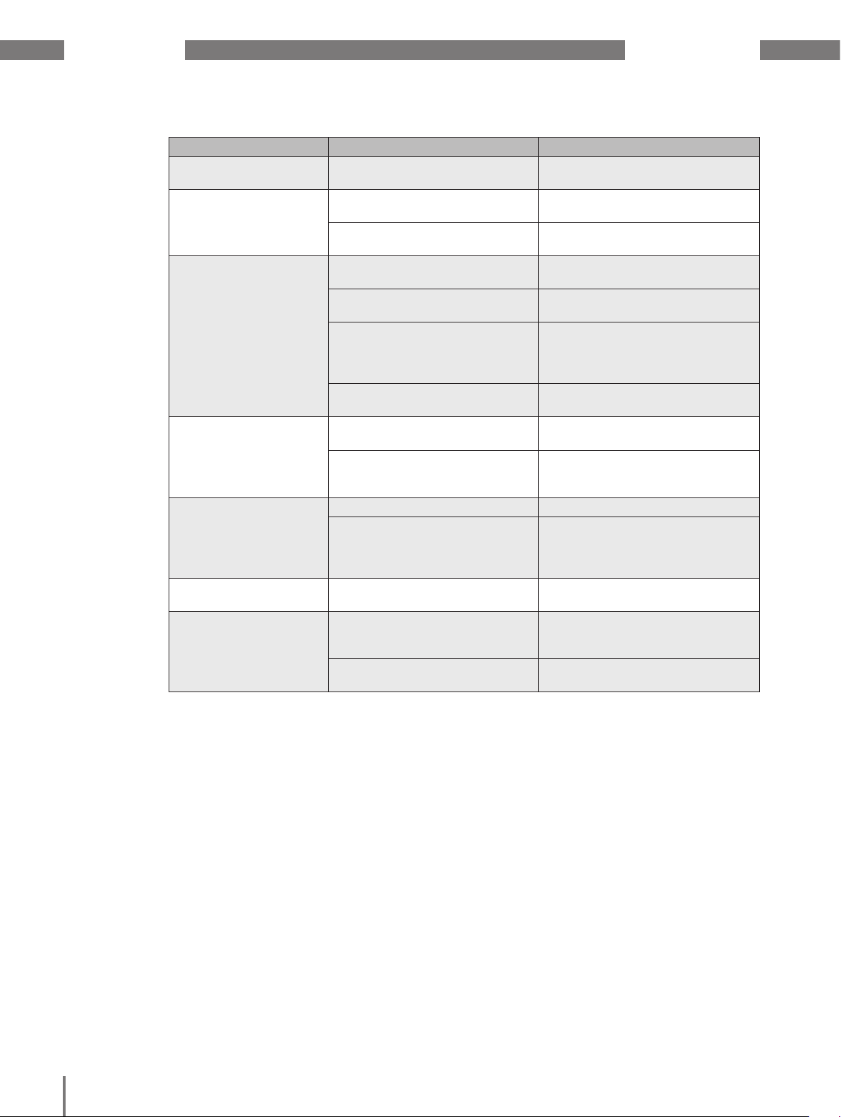
UMG 509-PRO www.janitza.de
15. Procedure in the event of faults
Possible fault Cause Remedy
No display External fuse for the power
supply voltage has tripped.
No current display Measured voltage
isnotconnected.
Measurement current
isnotconnected.
Current displayed is too
high or too low.
Voltage displayed is too
high or too low.
Voltage displayed is too
low.
Phase shift ind/cap. A current circuit is assigned
Active power,
consumption/supply
reversed.
Current measurement in
the wrong phase.
Current transformer factor
is incorrectly programmed.
The current peak value
at the measurement input
was exceeded by harmonic
components.
The current at the measurement
input fell short of.
Measurement in the wrong
phase.
Voltage transformer incorrectly
programmed.
Measurement range exceeded. Use voltage transformers.
The peak voltage value
at themeasurement input
has been exceeded by
the harmonics.
to the wrong voltage circuit.
At least one current transformer
connection is mixed up/
reversed.
A current circuit is assigned
to the wrong voltage circuit.
Replace fuse.
Connect the measured voltage.
Connect measuring-circuit
current.
Check connection and correct
if necessary.
Read out and program the CT
ratio on the current transformer.
Install current transformer with
a larger CT ratio.
Install current transformer with
a smaller CT ratio.
Check connection and correct
if necessary.
Read out and program
the voltage transformer ratio
at the voltage transformer.
Attention! Ensure
the measurement inputs are
not overloaded.
Check connection and correct
if necessary.
Check connection and correct
if necessary.
Check connection and correct
ifnecessary.
87
Page 93
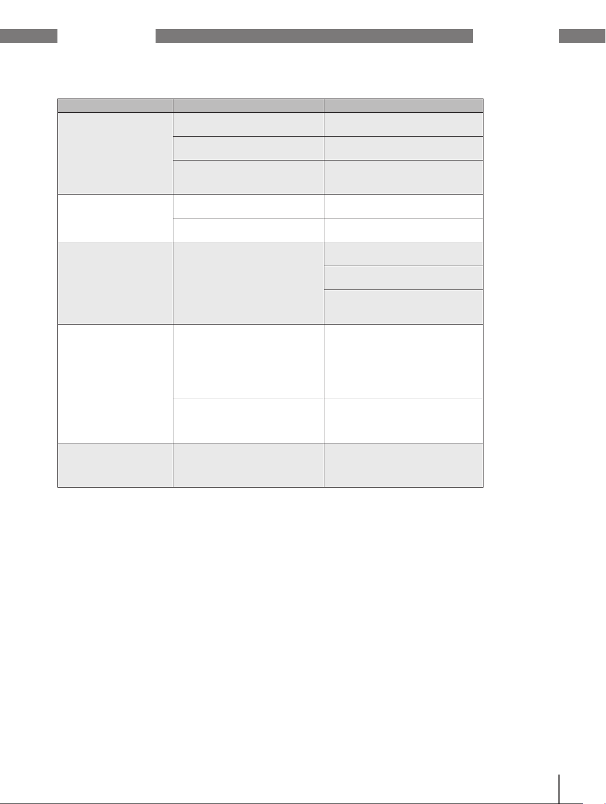
www.janitza.de UMG 509-PRO
Possible fault Cause Remedy
Active power too high
or too low.
An output is not
responding.
Measurement range
exceeded
display (overload)
No connection to the
device.
Device still does not
work despite the above
measures.
The programmed CT ratio
is incorrect.
The current circuit is assigned
to the wrong voltage circuit.
The programmed voltage
transformer ratio is incorrect.
The output was incorrectly
programmed.
The output was incorrectly
connected.
Voltage and current
measurement input
outside the metering range
(seethemeasurement range
exceeded chapter)
RS485
- Device address is incorrect.
- Different bus speeds
(baud rate).
- Wrong protocol.
- Termination missing.
Ethernet
- IP Device address is incorrect.
- Incorrect addressing mode
Device defective. Send the device to
Read out and program the CT
ratio on the current transformer
Check connection and correct
if necessary.
Read out and program
the voltage transformer ratio
at the voltage transformer.
Check the settings and correct
if necessary.
Check connection and correct
ifnecessary.
Check connection and correct
if necessary.
Use suitable voltage and current
transformers.
Read out and program
the voltage or CT ratio
onthetransformer.
- Correct the device address.
- Adjust speed (baud rate)
.
- Select the correct protocol.
- Terminate bus with termination
resistor.
- Correct the IP device address.
- Correct the IP address
assignment mode
the manufacturer for inspection
and testing along with
an accurate fault description.
88
Page 94

UMG 509-PRO www.janitza.de
16. Technical data
General
Net weight (with attached connectors) approx. 1080 g
Device dimensions approx. l = 144 mm, w = 144 mm, h = 75 mm
Battery
Clock (in temperature range -40°C to 85°C) +-5 ppm (corresponding to approx. 3 minutes
Transport and storage
The following information applies to devices which are transported or stored in the original
packaging.
Free fall 1 m
Temperature -25 °C to +70 °C
Ambient conditions during operation
The device is intended for weather-protected, stationary use.
The device must be connected to the ground wire connection! Protection class I in acc.
with IEC 60536 (VDE 0106, Part 1).
Working temperature range -10 °C to +55 °C
Relative humidity 5 to 95% RH (at 25°C without condensation)
Operating altitude 0 to 2000 m above sea level
Pollution degree 2
Installation position upright
Ventilation forced ventilation is not required.
Protection against ingress of solid foreign
bodies and water
• Front
• Rear side
type Li-Mn CR2450, 3V (approval i.a.w. UL 1642)
per year)
IP40 in acc. with EN60529
IP20 in acc. with EN60529
16. 1 Supply voltage
Supply voltage
Installations of overvoltage category 300V CAT III
Protection of the supply voltage (fuse) 6 A, type B (approved i.a.w. UL/IEC)
230V option:
- Nominal range
- Operating range
- Power consumption
95 V to 240 V (50/60 Hz) / DC 80 V to 300 V
+-10% of nominal range
max. 7 W / 14 VA
24V option:
• Nominal range
• Operating range
• Power consumption
48 V to 110 V (50/60 Hz) or DC 24 to 150 V
+-10% of nominal range
max. 9 W / 13 VA
Terminal connection capacity (supply voltage)
Connectable conductors. Only one conductor can be connected per terminal!
Single core, multi-core, fine-stranded 0.2 - 2.5 mm2, AWG 24 - 12
Terminal pins, core end sheath 0.25 - 2.5 mm
2
Tightening torque 0.5 - 0.6 Nm
Stripping length 7 mm
89
Page 95

www.janitza.de UMG 509-PRO
16. 2 Voltage and current measurement
Current measurement
Rated current 5 A
Resolution 0.1 mA
Metering range 0.005 to 7 Amps
Measurement range exceeded (overload) as of 7.5 Amps
Crest factor 2.4
Overvoltage category 230 V option: 300 V CAT III
24 V option: 300V CAT II
Measurement surge voltage 4 kV
Power consumption approx. 0.2 VA (Ri=5 mOhm)
Overload for 1 sec. 120 A (sinusoidal)
Sampling rate 20 kHz / phase
Voltage measurement
The voltage measurement inputs are suitable for measurements in the following power
supply systems:
Three-phase 4-conductor systems with
rated voltages up to
Three-phase 3-conductor systems with
rated voltages up to
From a safety and reliability perspective, the voltage measurement inputs are designed
as follows:
Overvoltage category 600V CAT III
Measurement surge voltage 6 kV
Protection of voltage measurement 1 - 10 A
Metering range L-N 01) to 600 Vrms
Metering range L-L 01) to 1000 Vrms
Resolution 0.01 V
Crest factor 1.6 (related to 600 Vrms)
Impedance 4 MOhm / phase
Power consumption approx. 0.1 VA
Sampling rate 20 kHz / phase
Transients > 50 µs
Frequency of the fundamental oscillation
- Resolution
417 V / 720 V
347 V / 600 V UL listed
600 V
40 Hz to 70 Hz
0.001 Hz
1 ) The device can only determine measured values, if an L-N voltage of greater than 10 Veff or an L-L voltage of greater than 18 Veff is applied to at least
one voltage measurement input.
Measurement precision phase angle
0,075 °
90
Page 96

UMG 509-PRO www.janitza.de
Terminal connection capacity (voltage and current measurement)
Connectable conductors. Only one conductor can be connected per terminal!
Single core, multi-core, fine-stranded 0.2 - 2.5 mm2, AWG 24-12
Terminal pins, core end sheath 0.25 - 2.5 mm
Tightening torque 0.5 - 0.6 Nm
Stripping length 7 mm
16. 3 Residual current monitoring
Residual current monitoring (RCM)
Rated current 30 mAmps
Metering range 0 to 40 mAmps
Triggering current 100 µA
Resolution 1 µA
Crest factor 1.414 (related to 40 mA)
Burden 4 Ohm
Overload for 1 sec. 5 A
Sustained overload 1 A
Overload for 20 ms 50 A
Residual current monitoring i.a.w. IEC/TR 60755 (2008-01), type A
2
Maximum external burden 300 Ohm (for cable break detection)
Terminal connection capacity (residual current monitoring)
Connectable conductors. Only one conductor can be connected per terminal!
Rigid/flexible 0.14 - 1.5 mm2, AWG 28-16
Flexible with core end sheath without
0.20 - 1.5 mm
2
plastic sleeve
Flexible with core end sheath with plastic
0.20 - 1.5 mm
2
sleeve
Stripping length 7 mm
Tightening torque 0.20 - 0.25 Nm
Cable length up to 30 m unshielded, from 30 m shielded
Potential separation and electrical safety for the residual current monitoring inputs
• The RCM measurement inputs are double-insulated from the current and voltage
measurement inputs as well as the supply voltage.
• There is no insulation from the temperature measurement input.
• There is only a functional insulation from the Ethernet, Profibus and RS485 interfaces
and the digital I/Os.
• The residual current transformer connected and the lines to be measured must each
have at least one additional or a basic insulation per IEC61010-1:2010 for the mains
voltage present.
91
Page 97
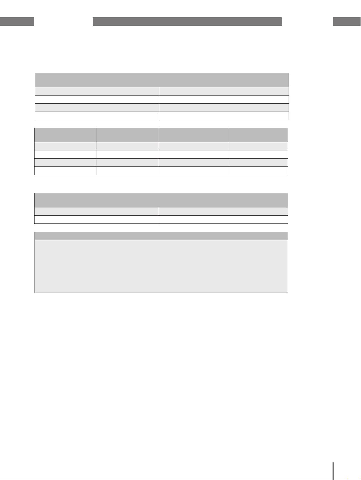
www.janitza.de UMG 509-PRO
16. 4 Temperature measurement input
Temperature measurement input
3-wire measurement
Update time 1 second
Connectable sensors PT100, PT1000, KTY83, KTY84
Total burden (sensor + cable) max. 4 kOhm
Cable length up to 30 m unshielded, from 30 m shielded
Sensor type Temperature range Resistor range Measurement
uncertainty
KTY83 -55 °C to +175 °C 500 Ohm to 2.6 kOhm ± 1.5% rng
KTY84 -40 °C to +300 °C 350 Ohm to 2.6 kOhm ± 1.5% rng
PT100 -99 °C to +500 °C 60 Ohm to 180 Ohm ± 1.5% rng
PT1000 -99 °C to +500 °C 600 Ohm to 1.8 kOhm ± 1.5% rng
Terminal connection capacity (temperature measurement input)
Connectable conductors. Only one conductor can be connected per terminal!
Single core, multi-core, fine-stranded 0.08 - 1.5 mm
Terminal pins, core end sheath 1 mm
2
2
Potential separation and electrical safety for the temperature measurement input
• The temperature measurement input is double-insulated from the current and voltage
measurement inputs, as well as the supply voltage.
• There is no insulation from the RCM measurement input.
• There is only a functional insulation from the Ethernet, Profibus and RS485 interfaces
and the digital I/Os.
• The external temperature sensor must be double insulated from the system parts
that carry voltages that are dangerous to touch (per IEC61010-1:2010).
92
Page 98

UMG 509-PRO www.janitza.de
16. 5 Digital inputs and outputs
Digital inputs
2 Digital inputs with a joint earth
Maximum counter frequency 20 Hz
Response time (Jasic program) 200 ms
Input signal present 18 V to 28 V DC (typical 4 mA)
Input signal not present 0 to 5 V DC, current less than 0.5 mA
Cable length up to 30 m unshielded, from 30 m shielded
Digital outputs
2 digital outputs with a joint earth; opto coupler, not short-circuit proof
Supply voltage 20 V - 30 V DC (SELV or PELV supply)
Switching voltage max. 60 V DC, 30 V AC
Switching current max. 50 mAeff AC/DC
Response time (Jasic program) 200 ms
Output of voltage dips 20 ms
Output of voltage exceedance events 20 ms
Switching frequency max. 20 Hz
Cable length up to 30 m unshielded, from 30 m shielded
Terminal connection capacity (digital inputs and outputs)
Rigid/flexible 0.14 - 1.5 mm2, AWG 28-16
Flexible with core end sheath without
0.25 - 1.5 mm
2
plastic sleeve
Flexible with core end sheath with plastic
0.25 - 0.5 mm
2
sleeve
Tightening torque 0.22 - 0.25 Nm
Stripping length 7 mm
Potential separation and electrical safety for the digital inputs and outputs
• The digital inputs and outputs are double-insulated from the current and voltage
measurement inputs, as well as the supply voltage.
• There is only a functional insulation from the Ethernet, Profibus and RS485 interfaces
and the digital I/Os, and from one another.
• The external auxiliary voltage to be connected must be compliant with SELV or PELV.
93
Page 99
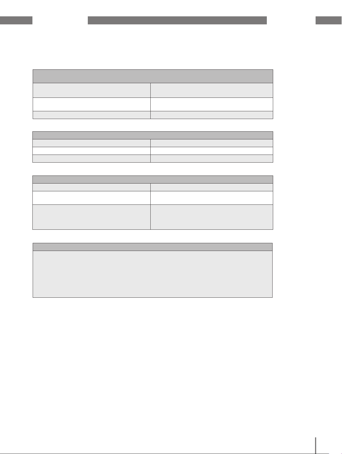
www.janitza.de UMG 509-PRO
16. 6 Interfaces
RS485 interface
3-wire connection with GND, A, B
Protocol Modbus RTU/slave, Modbus RTU/master,
Modbus RTU /gateway
Transmission rate 9.6 kbps, 19.2 kbps, 38.4 kbps, 57.6 kbps,
115.2 kbps, 921.6 kbps
Termination resistor can be activated by micro switch
Profibus interface
Connection SUB D 9-pin
Protocol Profibus DP/V0 per EN 50170
Transmission rate 9.6 kBaud to 12 MBaud
Ethernet interface
Connection RJ45
Function Modbus gateway, embedded web server
(HTTP)
Protocols CP/IP, EMAIL (SMTP), DHCP client (BootP),
Modbus/TCP, Modbus RTU over Ethernet,
FTP, ICMP (Ping), NTP, TFTP, BACnet
(optional), SNMP
Potential separation and electrical safety for the interfaces
• The Ethernet, Profibus and RS485 interfaces are double-insulated from the current and
voltage measurement inputs as well as the supply voltage.
• There is only a functional insulation from the RSM measurement inputs and thermistor
inputs as well as from the digital I/Os, and from one another.
• The interfaces for the devices connected here must have a double or reinforced
insulation to mains voltages (in accordance with IEC 61010-1: 2010).
94
Page 100

UMG 509-PRO www.janitza.de
16. 7 Function parameters
The measurements are carried out via current transformer ../5 A with a frequency of 50 / 60 Hz.
Function Symbol Precision class Metering range Display range
Total active power P 0.2 5) (IEC61557-12) 0 to 15.3kW 0 W to 9999 GW *
Total reactive power QA 6), Qv
Total apparent power SA, Sv
6)
1 (IEC61557-12) 0 to 15.3 kvar 0 varh .. 9999 Gvar *
6)
0.2 5) (IEC61557-12) 0 to 15.3 kVA 0 VA to 9999 GVA *
Total active energy Ea 0.2S
Total reactive energy ErA 6), ErV
6)
5)7)
(IEC61557-12) 0 to 15.3 kWh 0 Wh to 9999 GWh *
1 (IEC61557-12) 0 to 15.3 kvarh 0 varh .. 9999 Gvarh *
Total apparent energy EapA,EapV 6)0.2 5) (IEC61557-12) 0 to 15.3 kVAh 0 VAh to 9999 GVAh *
Frequency f 0.05 (IEC61557-12) 40 to 70 Hz 40 Hz to 70 Hz
Phase current I 0.2 (IEC61557-12) 0.005 to 7 Amps 0 A to 9999 kA
Measured neutral conductor current
IN 0.2 (IEC61557-12) 0.005 to 7 Amps 0 A to 9999 kA
Residual currents I5, I6 IDIFF 1 (IEC61557-12) 0 to 40 mAmps 0 A to 9999 kA
Computed neutral conductor current
INc 0.5 (IEC61557-12) 0.005 to 21 A 0 A to 9999 kA
Voltage U L-N 0.1 (IEC61557-12) 10 to 600 Vrms 0 V to 9999 kV
Voltage U L-L 0.1 (IEC61557-12) 18 to 1000 Vrms 0 V to 9999 kV
Power factor PFA, PFV 0.5 (IEC61557-12) 0.00 to 1.00 0 to 1
Short-term flicker, long-term flicker
Pst, Plt - - -
Voltage dips Udip 0.2 (IEC61557-12) 10 to 600 Vrms 0 V to 9999 kV
Voltage increases Uswl 0.2 (IEC61557-12) 10 to 600 Vrms 0 V to 9999 kV
Transient overvoltages Utr 0.2 (IEC61557-12) 10 to 600 Vrms 0 V to 9999 kV
Voltage interruptions Uint - - -
Voltage unbalance
Voltage unbalance
1)
2)
Unba 0.2 (IEC61557-12) 10 to 600 Vrms 0 V to 9999 kV
Unb 0.2 (IEC61557-12) 10 to 600 Vrms 0 V to 9999 kV
Voltage harmonics Uh Cl. 1 (IEC61000-4-7) Up to 2.5 kHz 0 V to 9999 kV
THD of the voltage
THD of the voltage
3)
4)
THDu 1.0 (IEC61557-12) Up to 2.5 kHz 0% to 999 %
THD-Ru 1.0 (IEC61557-12) Up to 2.5 kHz 0% to 999 %
Current harmonics Ih Cl. 1 (IEC61000-4-7) Up to 2.5 kHz 0 A to 9999 kA
THD of the current
THD of the current
3)
4)
THDi 1.0 (IEC61557-12) Up to 2.5 kHz 0% to 999 %
THD-Ri 1.0 (IEC61557-12) Up to 2.5 kHz 0% to 999 %
95
Mains signal voltage (interhar-
MSV - - -
monics voltage)
Declarations
1) In relation to the amplitude.
2) In relation to phase and amplitude.
3) In relation to fundamental oscillation.
4) In relation to effective value.
5) Precision class 0.2 with.../ 5A converter.
Precision class 0.5 with.../ 1A converter.
* When the max. total working value s have been reached, the display
returns to 0 W.
6) Calculation from fundamental oscillation.
7) Precision class 0.2S per IEC62053-22
 Loading...