

Page 1
Document no. 1.042.015.5n from firmware rel. 2.0 / hardware rel. 20
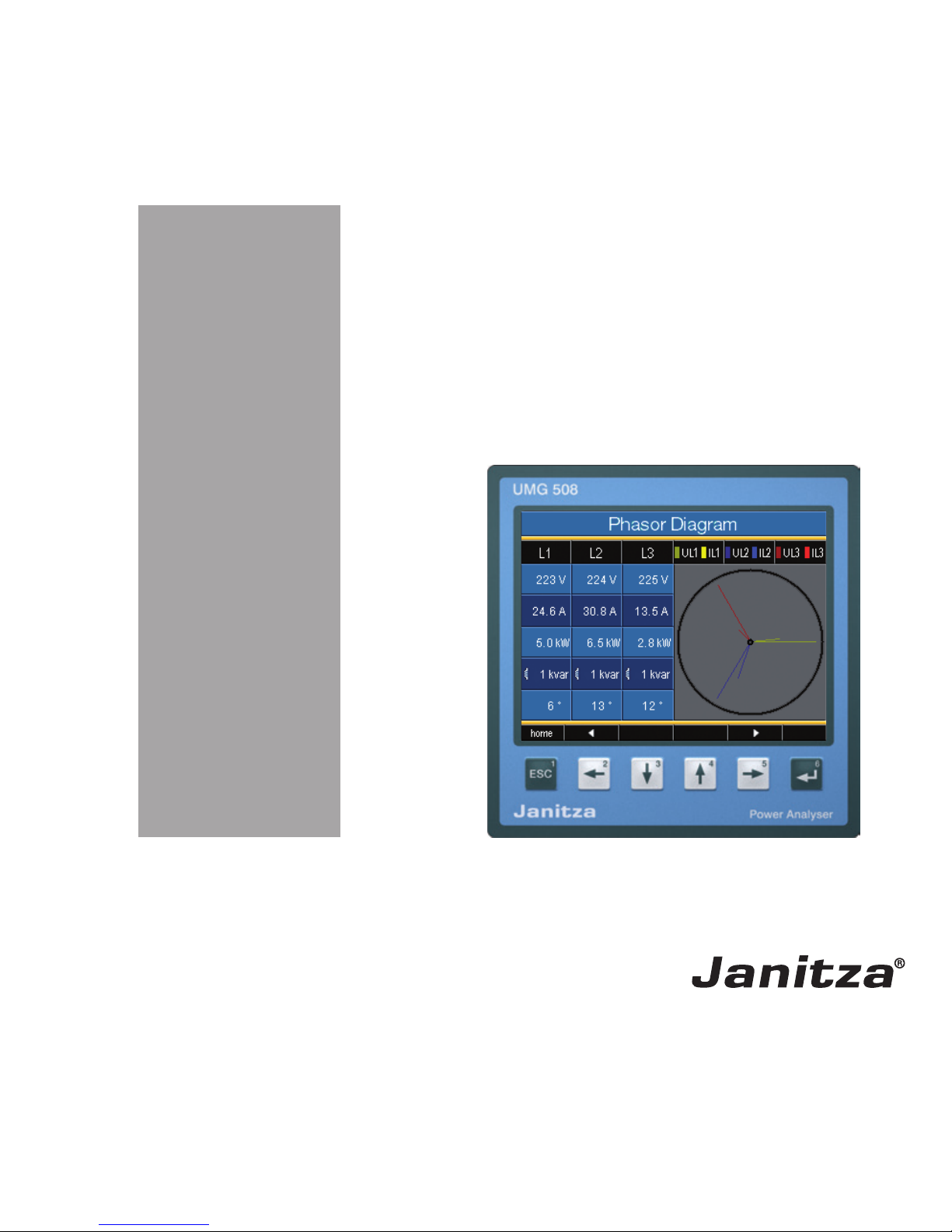
Power Analyser
UMG 508
Operating manual and
technical data
Art. no. 33.03.121 (UL)
Janitza electronics GmbH
Vor dem Polstück 1
D-35633 Lahnau
Support Tel. 0049 6441 9642-22
Fax 0049 6441 9642-30
e-mail: info@janitza.com
Internet: http://www.janitza.com
www.janitza.com
Page 2

2
UMG 508
General 3
Goods-in Check 6
Description 8
Intended Use 8
Features 9
Measurement Method 10
GridVis network analysis software 11
Assembly 12
Place of Installation 12
Installation extradata 12
Front Board Cutout 12
Ethernet Connection 13
Fixing 13
Installation 14
Supply Voltage 14
Voltage Measurement 16
Current measurement 24
RS485 28
Ethernet 32
Digital outputs 34
Digital Inputs 36
Operation 38
Measurement value displays 39
"Home“ measurement value display 40
Select measurement value display 41
Call up additional information 42
Delete min/max values individually 43
List of transients 44
List of events 45
Configuration 46
Language 47
Communication 48
Measurement 50
Transients 56
Events 58
Display 60
System settings 62
Password 63
Delete minimum and maximum values 64
Delete power meters 65
Extensions 68
Initialization 71
Applying the supply voltage 71
Apply measurement voltage 72
Rotary field direction 72
Applying measurement current 73
Checking the power measurement 75
Checking communication 75
Service and Maintenance 81
Technical data 85
Dimensioned drawings 94
Measurement value displays overview 97
Connection example 100
Page 3

3
UMG 508
General
Copyright
This handbook is subject to the legal regulations of copyright law protection and may not be
mechanically or electronically photocopied or
reprinted in full in or parts and, without the legal,
written permission of
Janitza electronics GmbH,
Vor dem Polstück 1,
D 35633 Lahnau, Germany,
may not be reproduced or further publication in
any other way.
Protected trademarks
All trademarks and the resulting rights belong to
the respective owners of the rights.
Disclaimer
Janitza electronics GmbH does not accept any
liability for errors or deficits in this handbook
and is not obliged to keep the contents of this
handbook updated.
Comments on the handbook
We welcome your comments. If anything in this
handbook seems unclear, please let us know
and send us an EMAIL to:
info@janitza.de
Page 4

4
UMG 508
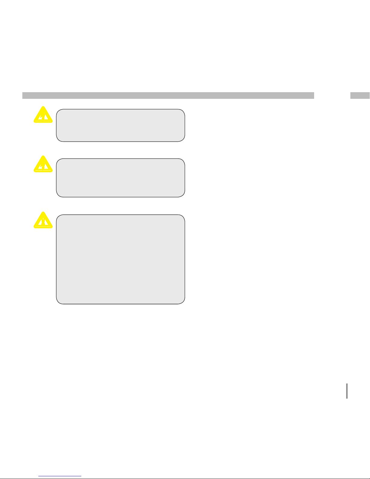
Meaning of Symbols
The following pictograms are used in this handbook:
Gefährliche Spannung!
Danger of death or risk of major injury.
Disconnect the system and device before beginning any work.
Protective ground connection.
Caution!
Please pay attention to the documentation. This symbol should warn against
possible dangers that can occur during
assembly, initialization and use.
m
c
Inductive.
The voltage lags the current
Capacitive.
The voltage lags the current.
C
Note.
Page 5
5
UMG 508
Application Information
Please read this operating manual and all other
publications that have to be consulted to work
with this product (particularly for installation,
operation or maintenance).
Please pay attention to all safety regulations and
warning information. If you fail to follow the information, it can result in personal damage and/
or damages to the product.
Any unauthorized change or use of this device
beyond the specified mechanical, electrical or
other operating limits can cause personal damage and/or damage to the product.
Any such unauthorized change represents "misuse" and/or "negligence" in the sense of guarantee for the product and therefore makes the
guarantee covering possible consequential damages void.
This device is to be exclusively operated and
maintained by a specialist.
Specialists are persons who, due to their relevant training and experience, are capable of recognizing risks and avoiding possible hazards
that can be caused when operating or servicing
the device.
When using the device, the necessary legal and
safety regulations should be considered additionally for the respective application case.
Caution!
If the device is not operated according
to the operating manual, protection is
no longer ensured and the device may
cause dangers.
c
Cables with single wires must be provided with ferrules.
Only screw plugs with the same pole
number and the same type of construction can be plugged together.
m
m
Page 6
6
UMG 508
The installation and initialization instructions also describe options that do
not belong to the scope of supply.
Goods-in Check
Correct and safe operation of this device is
subject to appropriate transportation, correct
warehousing, installation and assembly as well
as careful operation and maintenance. If it can
be assumed that safe operation without any
danger is no longer possible, the device must
be taken out of operation immediately and secured against unintentional initialization.
Unpacking and packing must take place, with
the usual care without applying force and using
suitable tools. The devices must be checked for
perfect condition with visual tests.
It should be assumed that risk-free operation is
not possible if, for example:
• There is visible damage,
• it no longer works due despite the main supply being intact,
• has been subject to unfavorable conditions
(e.g. storage outside of the authorized climate
limits without adaptation to the room climate,
thawing etc.) over a longer period of time or
transport stresses (e.g. a fall from a height, including without any visisble external damage
etc).
• Please check the delivered items for completeness before starting with the installation of
the device.
All supplied options and design versions are described on the delivery note.
All screw clamps that belong to the
scope of supply are attached to the
device.
C
C
C
Page 7

7
UMG 508
Art.no. Description
13 10 539 Profibus plug, 9-pole DSUB, with integrated switchable terminating
resistors.
1)
Refer to delivery note for article number.
Scope of Supply
Available accessories
Quantity Art.no. Description
1 52 21 xxx 1) UMG508
1 33 03 121 operating manual
1 51 00 116 CD with the following contents:
- "GridVis“ programming software,
- DEscription of functions, GridVis, UMG508,
- UMG508, GSD file "U5080C2C.GSD“ for Profibus DP V0
1 10 01 818 screw clamp, pluggable, 2-pole (auxiliary power)
1 10 01 847 screw clamp, pluggable, 5-pole (voltage measurement 1-4)
1 10 01 822 screw clamp, pluggable, 8-pole (current measurement 1-4)
1 10 01 810 screw clamp, pluggable, 6-pole (digital outputs)
2 10 01 809 screw clamp, pluggable, 5-pole (digital inputs)
1 08 01 505 2m patch cable, twisted, gray (connection UMG508-PC/Switch/Hub)
1 52 19 301 fixing clips
Page 8

8
UMG 508
Description
Intended Use
The UMG508 is intended for measurements in
the building installation, on distributors, power
switches and bus bars.
Measurement voltages and measurement currents must come from the same network.
The UMG508 is suitable for installation in switch
boards with a fixed, weather-protected extradata.
The UMG508 can be used in 2, 3 and 4 supply
networks and in TN and TT networks.
The current measurement inputs of the UMG508
are connected using external ../1A or ../5A current transformers.
The measurement in medium and high-voltage
networks generally takes place using current
and voltage transformers.
The UMG508 can be used in residential and industrial areas.
Measurement results can be displayed, saved
and read-out using serial interfaces for further
processing.
Page 9

9
UMG 508
Features
• Front board installation, 144x144mm,
• Working temperature range -10°C .. +55°C,
• Colour graphic display 320x240, 256 colours, 6 keys,
• 8 digital inputs, 5 digital outputs,
• 16Bit A/transformer, data memory 256MByte Flash, SDRAM 32Mbyte,
• Continuous scanning of voltage and current measurement inputs with 20kHz,
• Frequency range of fundamental oscillation 40Hz .. 70Hz
• 4 voltage measurement inputs, 4 current measurement inputs,
• Measurement in TN and TT networks,
• RS485: Profibus DP/V0, Modbus RTU, Modbus-Master, BACnet (Option)
• Ethernet: Web-Server, EMAIL, BACnet (Option),TCP/IP, EMAIL (SMTP), DHCP-Client (BootP),
Modbus/TCP, Modbus RTU over Ethernet, FTP, ICMP (Ping), NTP, TFTP. BACnet (Option), SNMP.
• Detection of transients >50µs and storage with up to 16000 scanning points,
• Detection of more than 800 measurement values,
• Measurement of harmonics 1 to 40, for
- Uln, I, P (ref/supply) and
- Q (ind/cap),
• Programming own applications in Jasic.
Page 10

10
UMG 508
Measurement Method
The UMG508 measures without any gaps and
calculates all effective values over a 200ms Interval.
The UMG508 measures the real effective value
(TRMS) of the voltages and currents applied to
the measurement inputs.
Operating Concept
You can program the UMG508 in several ways
and call up measurement values.
• Direct- on the device using 6 keys and the
display.
• Using the programming softwareGridVis.
• Using the UMG508 homepagefor devices
with an Ethernet interface.
• Using the RS485 with theModbus-protocol.
You can change and call up data with the help
of the Modbus address list (stored on the enclosed data carrier).
Only operating the UMG508 using the integrated display and the 6 keys is described in this
operating manual.
The GridVis programming software and the
homepage have their own "online assistance“.
Page 11
11
UMG 508
GridVis network analysis software
The UMG508 can be programmed and readout with the GridVis network analysis software
included in the scope of supply. A PC must
be connected using a serial interface (RS485/
Ethernet) to the UMG508.
GridVis features
• Programming the UMG508.
• Configuration of recordings.
• Recordings read-out.
• Saving data in a database.
• Graphic presentation of measurement values.
• Programming specific applications for the client.
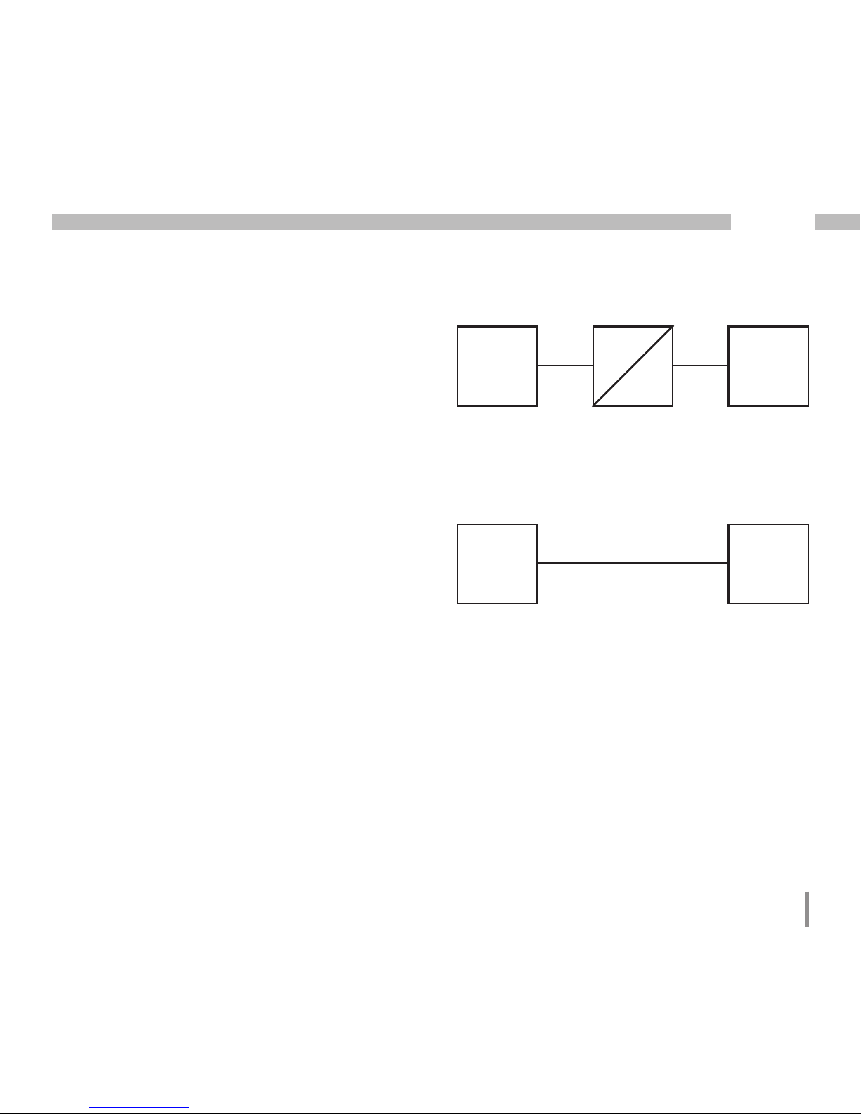
PC
UMG
508
Ethernet
Illu. Connection of a UMG508 to a PC using an
interface converter.
PC
UMG
508
RS232
RS485
Interface
Converter
Illu. Connection of a UMG508 to a PC using
Ethernet.
Page 12
12
UMG 508
Assembly
Place of Installation
The UMG508 is suitable for installation in fixed,
weather protected switch boards. Conducting
switch boards have to be grounded.
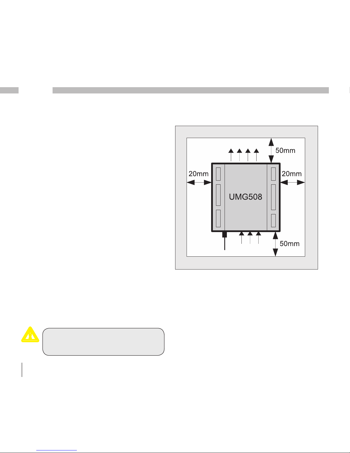
Installation extradata
In order to achieve sufficient ventilation, the
UMG508 has to be installed vertically. The clearance has to be at least 50mm at the top and
bottom and 20mm at the side.
Front Board Cutout
Cutout size: 138
+0.8
x 138
+0.8
mm
Failure to maintain the minimum clearances can destroy the UMG508 at
high environmental temperatures!
Wall
Airflow
Airflow
Ethernet
Connection
Illu. UMG508 installation extradata; view from
back.
m
Page 13
13
UMG 508
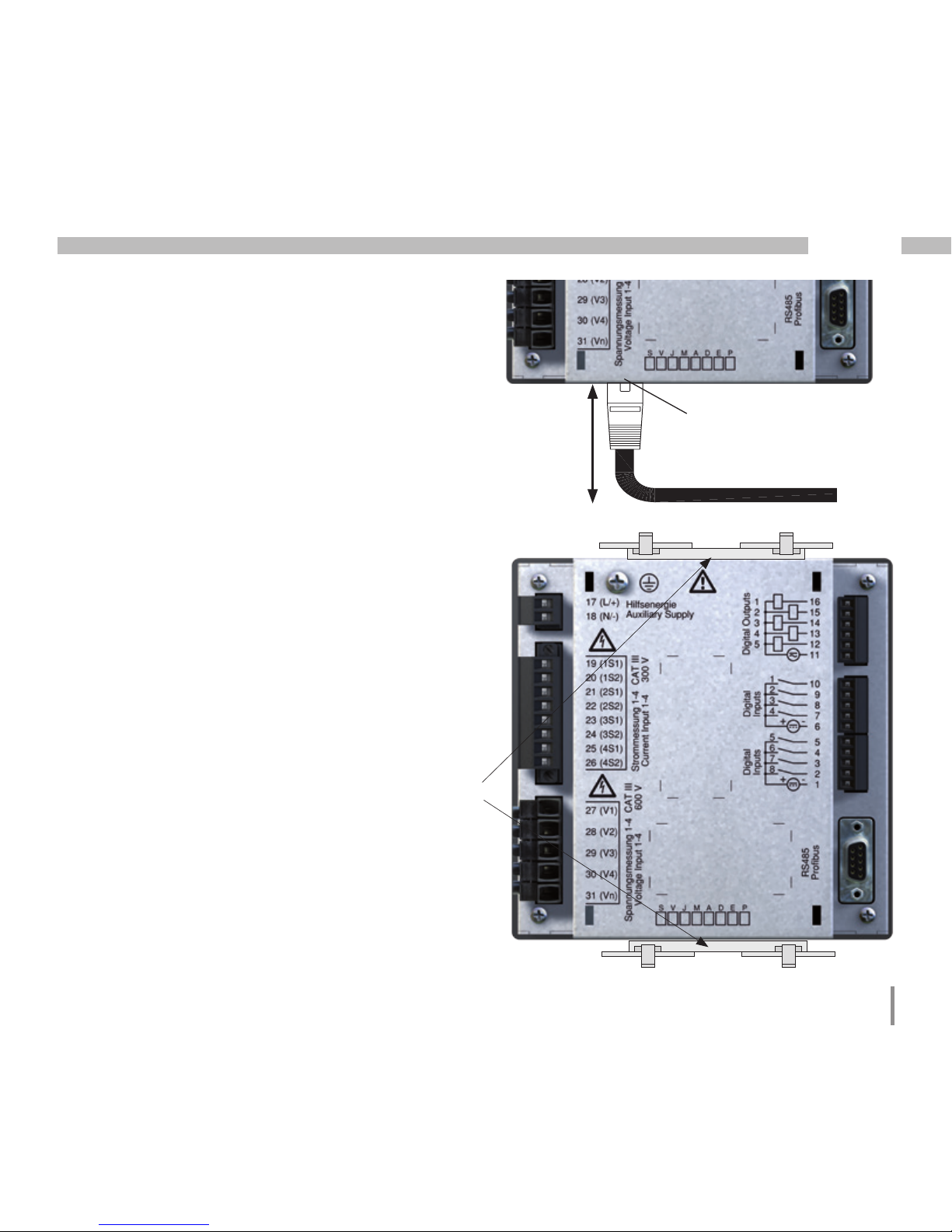
Ethernet Connection
Patch Cable
Ethernet Connection
The UMG508's Ethernet connection is located
on the underside of the housing.
Depending on the bending radius of the Ethernet cable and plug type, you must provide a
connection area beneath the UMG508.
The connection area beneath the UMG508
should not be less than 50 mm.
50 mm
Fixing
The UMG508 is fixed into the switch board with
two fixing clips that are each mounted on the
device at the top and bottom.
Fixing Clips
Page 14
14
UMG 508
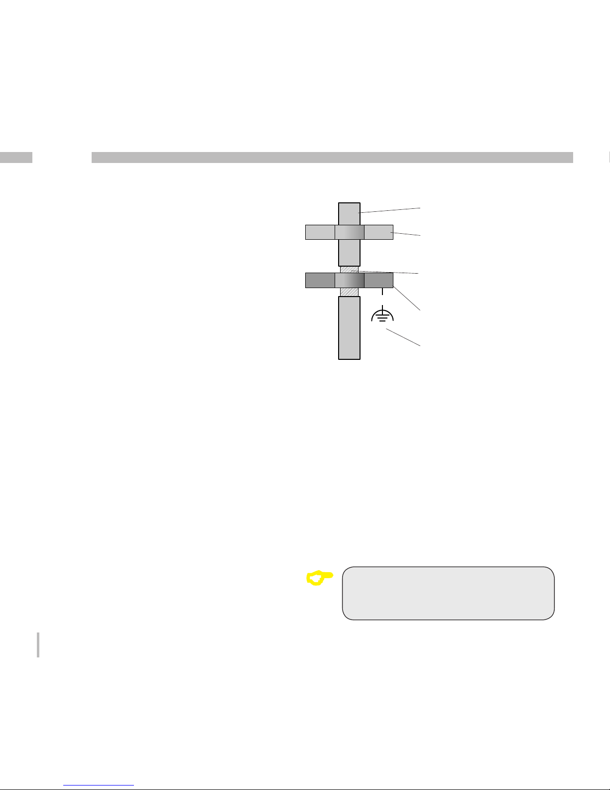
Installation
Protective Wire Connection
Use a ring cable lug for connecting the protective wire to the UMG508.
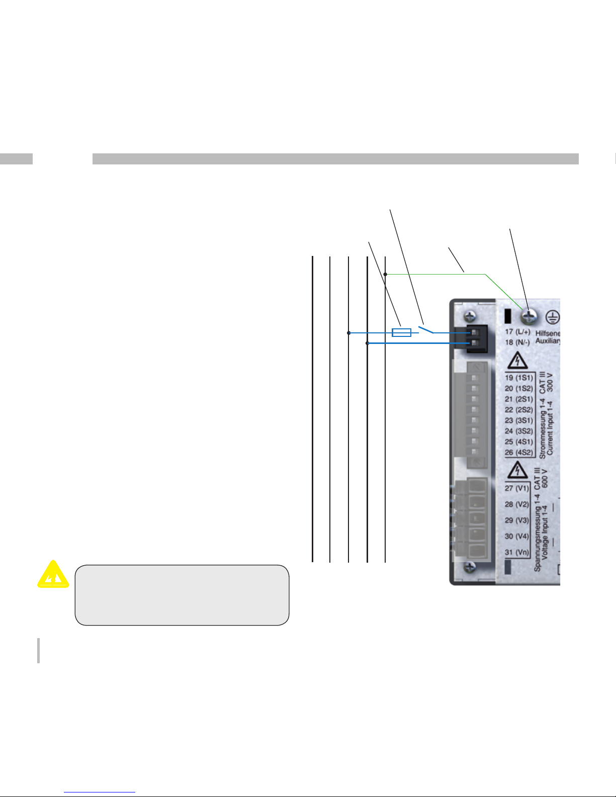
Supply Voltage
A supply voltage is required to operate the
UMG508. The type and level of the necessary
supply voltage is noted on the label.
Before applying the supply voltage, make sure
that the voltage and the frequency match the
details on the label!
The auxiliary voltage has to be connected via an
UL/IEC approved fuse (1A Class CC) or a circuit
breaker (1A C.Char.)
Illu. Connection example; connection of supply
voltage to a UMG508.
Separator
Fuse
L1 N PEL3L2
Protective wire
c
Warning - danger of death!
It is necessary for the protective wire
connection on the device to be connected with the system grounding.
Connection point for
protective wire
Page 15
15
UMG 508
- An isolator or circuit breaker must be
provided for the voltage supply in building installation.
- The isolator must be attached near
to the device and must be easy for the
user to access.
- The switch must be marked as a separator for this device.
-Voltages above the authorized voltage
range can destroy the device.
m
Warning!
The inputs for the supply voltage are
dangerous to touch!
c
Warning!
Please pay attention to the details on
the supply voltage provided on the
UMG508 label.
c
Page 16
16
UMG 508
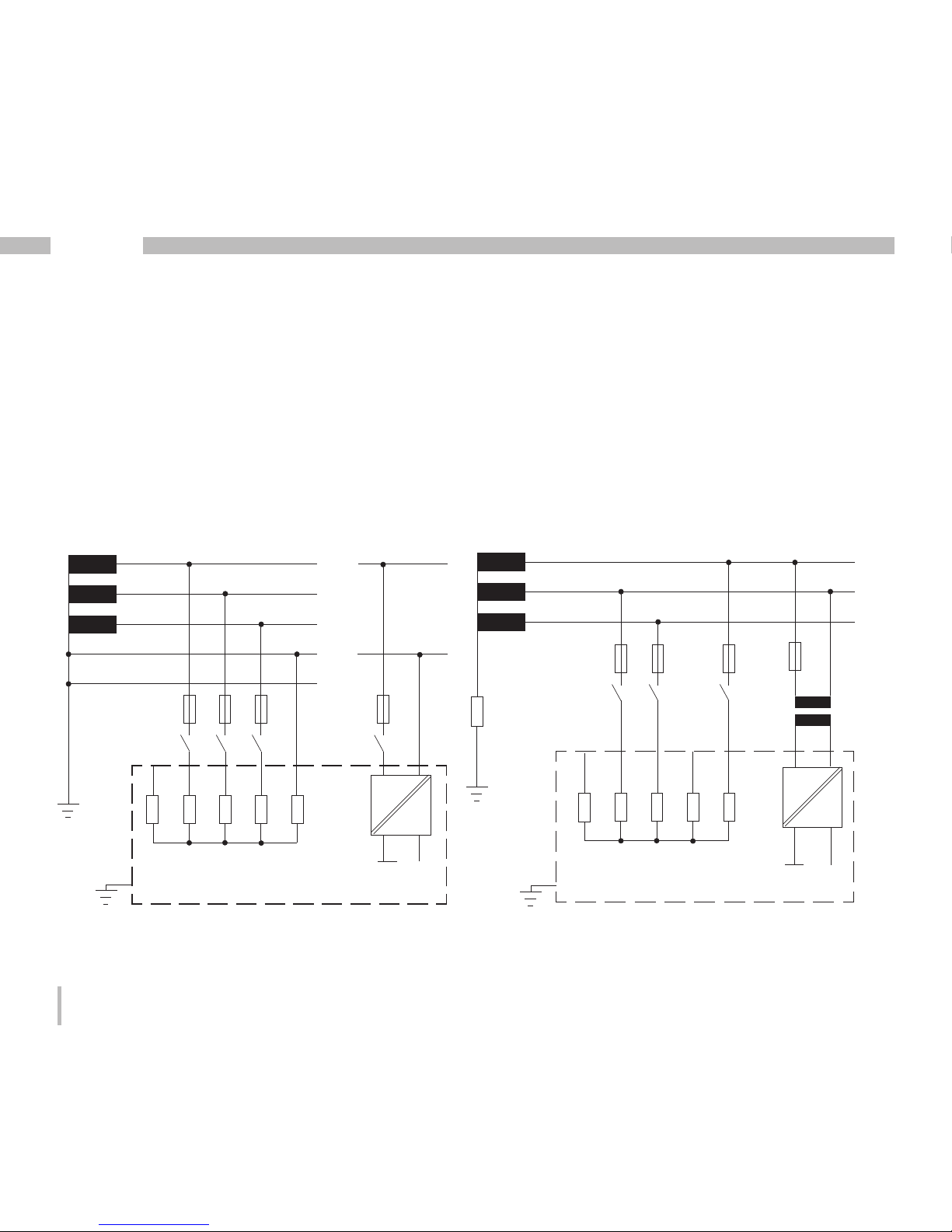
Illu. Basic circuit diagram, UMG508 in theTN-
network.
Voltage Measurement
Three-phase 4 conductor systems
The UMG508 can be used in three-phase 4 conductor systems (TN, TT network) with a grounded neutral wire. The bodies of the electrical
system are grounded.
Three-phase 3 conductor systems
The UMG508 is only suitable for use in IT networks with restrictions, because the measurement voltage is measured against the housing
potential and the input impedance of the device
causes a leakage current against ground. The
leakage current can cause isolation monitoring
in IT networks to respond.
Connection variations with a voltage transformer are suitable for IT networks without any restrictions.
Illu. Basic circuit diagram, UMG508 in the IT network without N.
600V 50/60Hz
DC
AC/DC
L2
L3
Auxiliary
power
Voltage measurement
4M
4M
4M
4M
V1
V3V2
4M
V4
System
grounding
Impedance
L1
UMG508
Vref
PE
347V/600V 50/60Hz
L2
L3
N
L1
N
L1
240V
50/60Hz
System
grounding
DC
AC/DC
Auxiliary
power
Voltage measurement
4M
4M
4M
4M
V1 V3V2 Vref
4M
V4
UMG508
Page 17
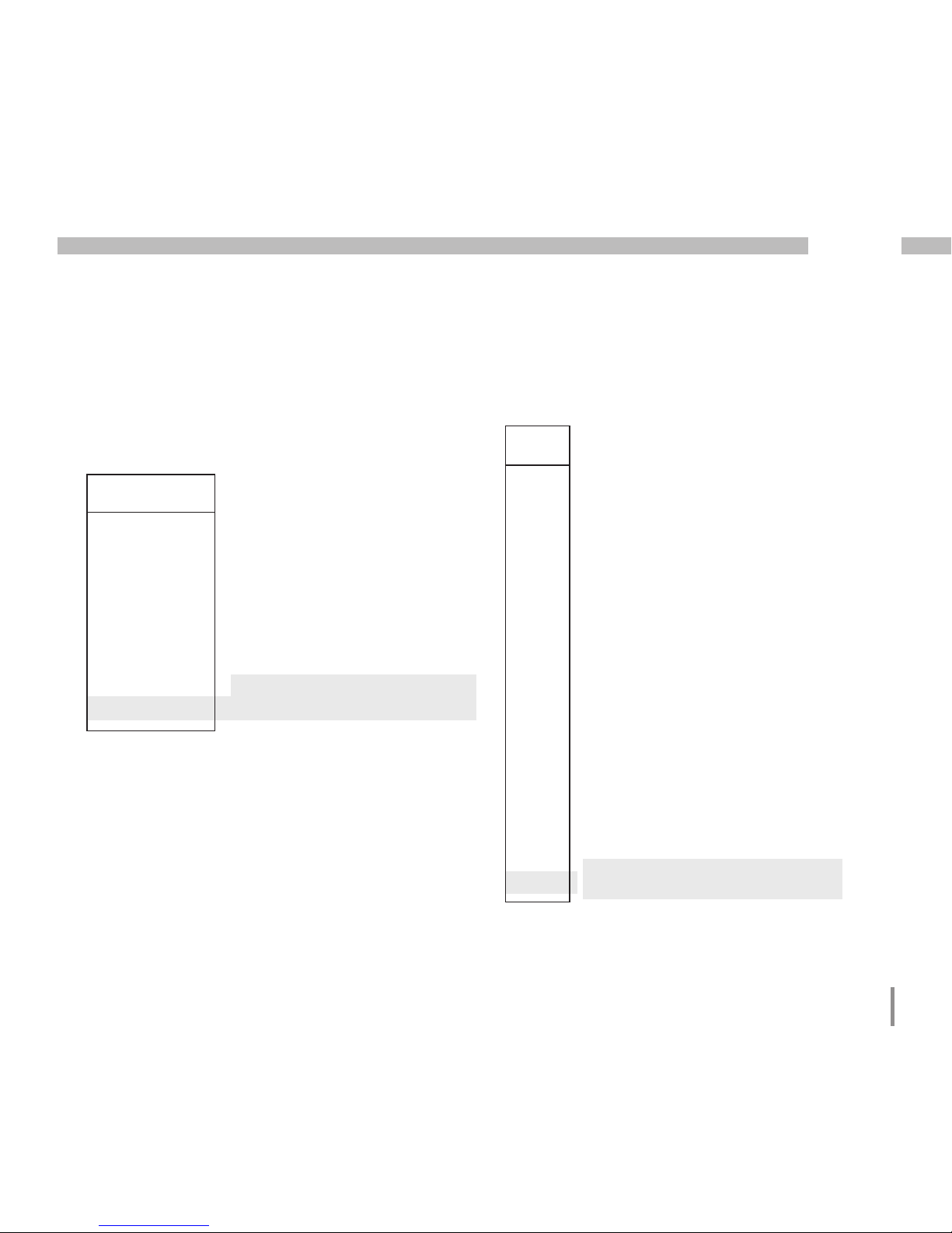
17
UMG 508
Maximum nominal voltage of
the network
Maximum nominal voltage of
the network according to UL
U
L-N
/ U
L-L
66V / 115V
120V / 208V
127V / 220V
220V / 380V
230V / 400V
240V / 415V
260V / 440V
277V / 480V
347V / 600V
Illu. Table of suitable network nominal voltages
for the voltage measurement inputs according
to EN60664-1:2003.
Three-phase 4 conductor systems with
grounded neutral wire.
Nominal Voltages
Lists of the networks and their nominal network
voltages in which the UMG508 can be used.
U
L-L
66V
115V
120V
127V
200V
220V
230V
240V
260V
277V
347V
380V
400V
415V
440V
480V
500V
577V
600V
Illu. Table of suitable network nominal voltages
for the voltage measurement inputs according
to EN60664-1:2003.
Ungrounded three-phase 3 conductor
systems.
Page 18
18
UMG 508
Voltage Measurement Inputs
The UMG508 has 4 voltage measurement inputs (V1, V2, V3, V4).
Measurement category
The voltage measurement inputs are suitable for
measurements in networks in which overvoltages in the measurement category 600V CATIII
can occur.
Frequency
The UMG508 requires the rated frequency for
measuring and calculating measurement values.
The UMG508 is suitable for measurements in
networks with a rated frequency in the range of
40Hz to 70Hz.
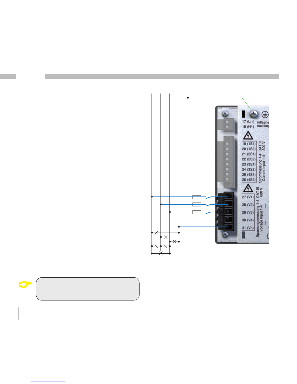
Illu. Connection example for voltage measurement.
A connection diagram does not have
to be configured for the measurement
inputs V4 and I4.
C
L1 N PEL3L2
10A
(UL/IEC listed)
Page 19

19
UMG 508
The following has to be considered when connecting the voltage measurement:
• A suitable separator is to be provided in order
to disconnect the UMG508 from the current
and voltage.
• The separator must be placed near to the
UMG508, labelled for the user and must be
easy to reach.
• Use for over current protection and circuit
breaker an UL/IEC approved fuse 10A Class
CC.
• The overcurrent protection device must have
a nominal value calculated for the short-circuit current at the connection point.
• Measurement voltages and measurement
currents must come from the same network.
Warning!
The voltage measurement inputs on the
UMG508 are dangerous to touch!
c
Warning!
The UMG508 is not suitable for measuring DC voltages.
Warning!
Voltages that exceed the authorized
network nominal voltages must be
connected using a voltage converter.
c
Warning!
The voltage measurement inputs may
not be used for voltage measurement
in SELV circuits (Safety Extra Low Voltage).
c
c
Page 20
20
UMG 508
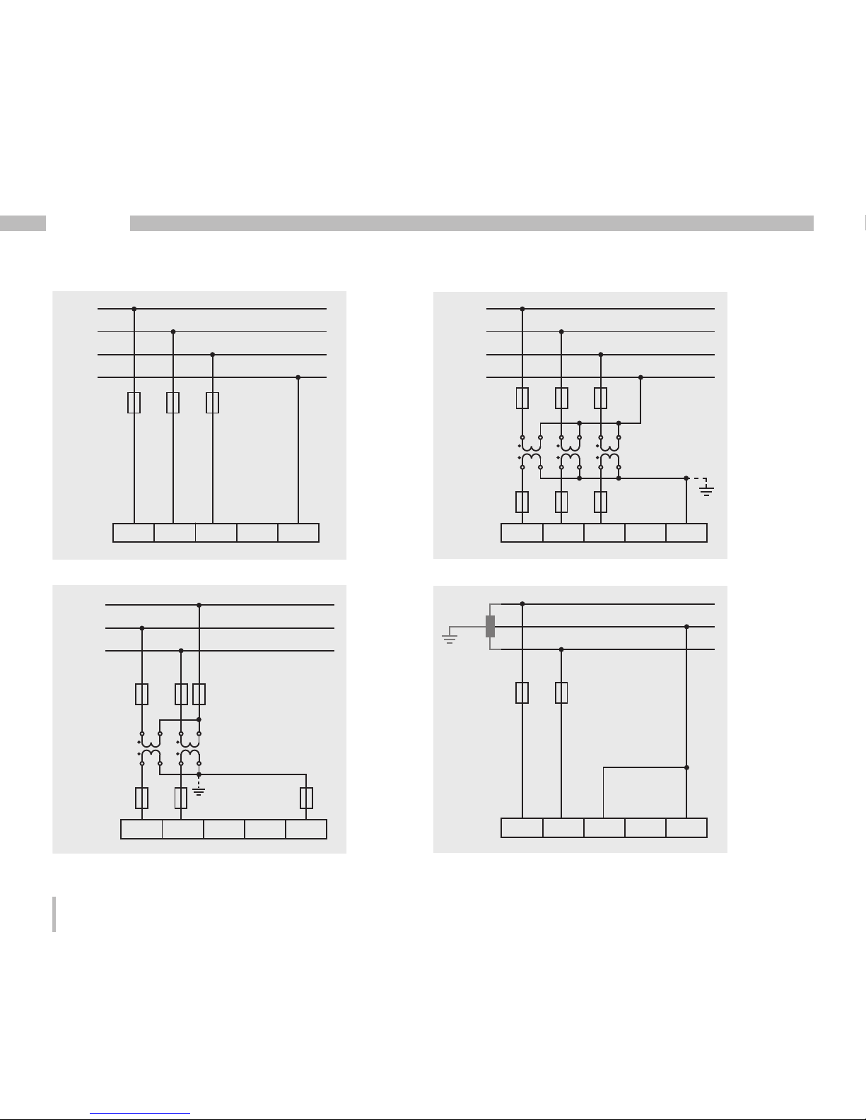
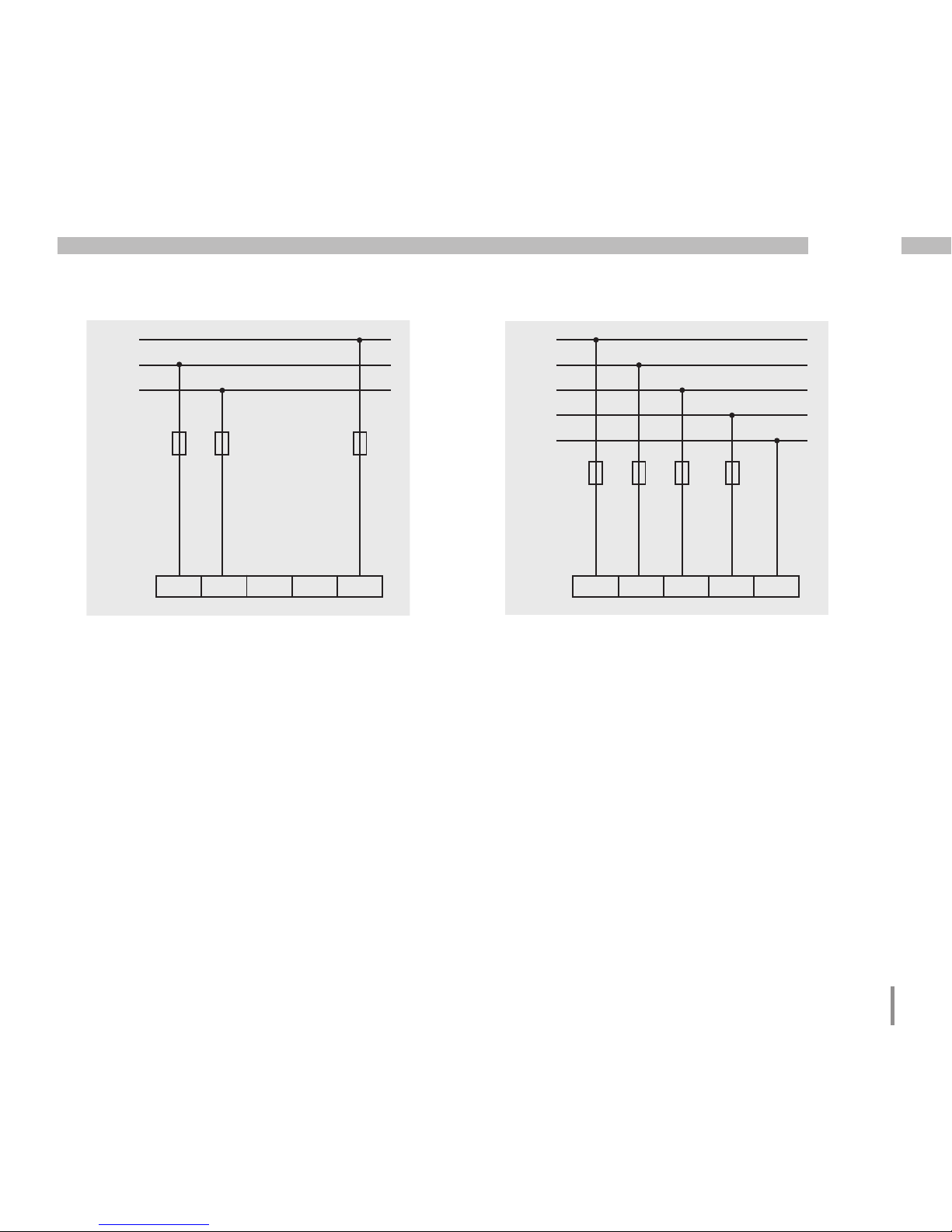
Connection diagrams, voltage measurement
L1
L2
L3
N
V
1 V2 V3 V4 Vref
3p 4wu
L1
L2
L3
N
V1 V2 V3 V4 Vref
3p 4w
L1
L2
L3
N
V1 V2 V3 V4 Vref
3p 4wu
L1
L2
L3
N
3p 4w
I1 I2 I3 I4
S1 S2 S1 S2 S1 S2 S1 S2
L1
L2
L3
N
V
1 V2 V3 V4 Vref
3p 4wu
L1
L2
L3
N
V
1 V2 V3 V4 Vref
3p 4w
L1
L2
V
1 V2 V3 V4 Vref
1p 2w
L1
L2
L3
V1 V2 V3 V4 Vref
3p 3wu
L1
L2
L3
N
V
1 V2 V3 V4 Vref
3p 4wu
L1
L2
V1 V2 V3 V4 Vref
1p 2w
L1
L2
L3
3p 2i0
I1 I2 I3 I4
S1 S2 S1 S2 S1 S2 S1 S2
L1
L2
L3
N
3p 4w
I1 I2 I3 I4
S1 S2 S1 S2 S1 S2 S1 S2
Page 21
21
UMG 508
L1
L2
L3
N
V
1 V2 V3 V4 Vref
3p 4wu
L1
L2
L3
N
V
1 V2 V3 V4 Vref
3p 4w
L1
L2
V
1 V2 V3 V4 Vref
1p 2w
L1
L2
L3
V
1 V2 V3 V4 Vref
3p 3wu
L1
L2
L3
V1 V2 V3 V4 Vref
3p 3w
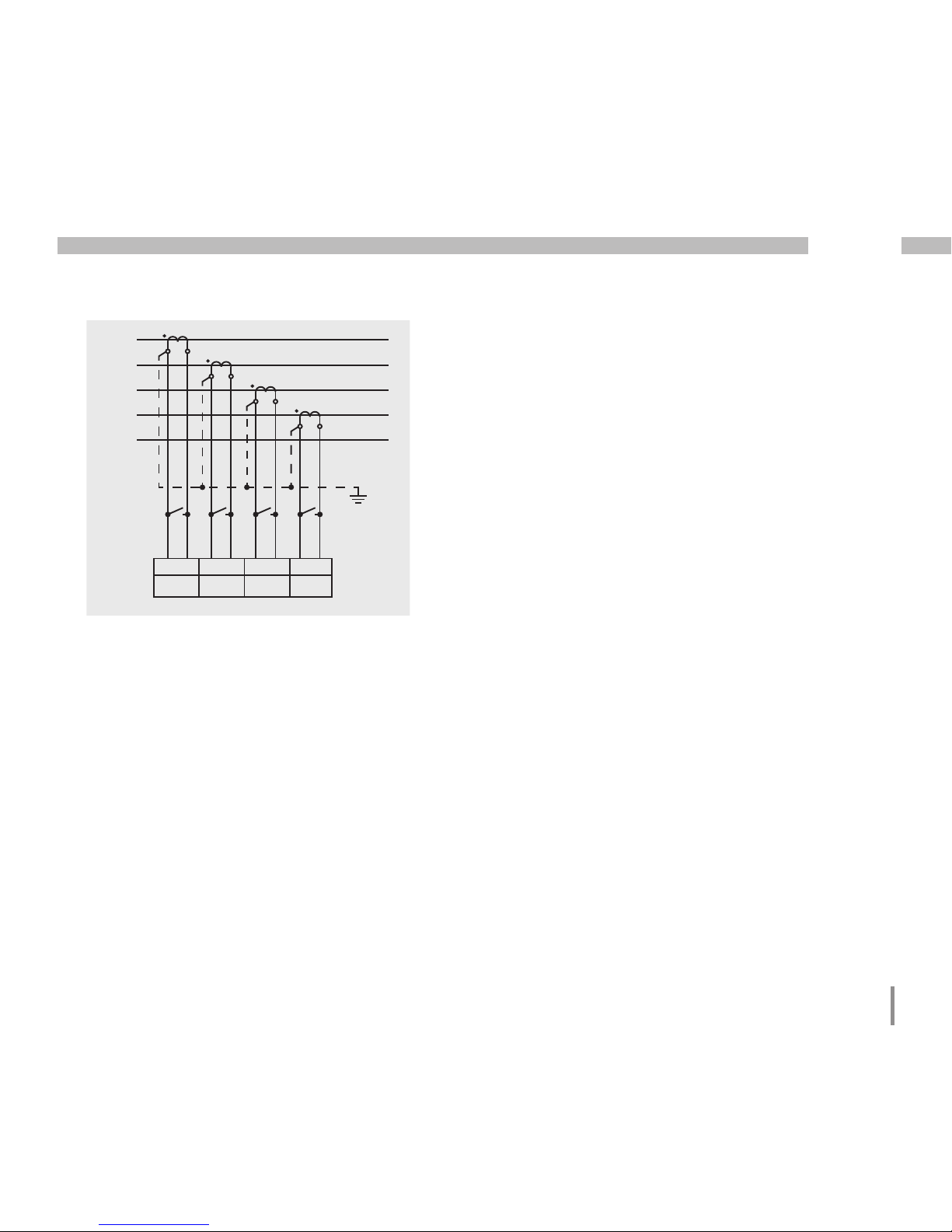
L
L
L
L
V
1 V2 V3 V4 Vref
3p 5w
N
L1
L2
L3
N
V
1 V2 V3 V4 Vref
3p 4wu
L1
L2
V
1 V2 V3 V4 Vref
1p 2w
L1
L2
L3
3p 2i0
I1 I2 I3 I4
S1 S2 S1 S2 S1 S2 S1 S2
L1
L2
L3
N
3p 4w
I1 I2 I3 I4
S1 S2 S1 S2 S1 S2 S1 S2
L
L
L
L
N
3p 5w
I1 I2 I3 I4
S1 S2 S1 S2 S1 S2 S1 S2
L
L
L
L
V1 V2 V3 V4 Vref
3p 5w
N
Page 22

22
UMG 508
Connection diagrams, current measurement
L1
L2
L3
N
3p 2i
I1 I2 I3 I4
S1 S2 S1 S2 S1 S2 S1 S2
L1
L2
L3
N
3p 4w
I1 I2 I3 I4
S1 S2 S1 S2 S1 S2 S1 S2
L1
L2
L3
N
3p 2i
I1 I2 I3 I4
S1 S2 S1 S2 S1 S2 S1 S2
L1
L2
L3
N
3p 2i
L1
L2
L3
3p 2i0
L1
L2
1p 2i
I1 I2 I3 I4
S1 S2 S1 S2 S1 S2 S1 S2
I1 I2 I3 I4
S1 S2 S1 S2 S1 S2 S1 S2
I1 I2 I3 I4
S1 S2 S1 S2 S1 S2 S1 S2
L1
L2
L3
N
3p 4w
I1 I2 I3 I4
S1 S2 S1 S2 S1 S2 S1 S2
L1
L2
L3
N
3p 2i
L1
L2
1p 2i
I1 I2 I3 I4
S1 S2 S1 S2 S1 S2 S1 S2
I1 I2 I3 I4
S1 S2 S1 S2 S1 S2 S1 S2
Page 23
23
UMG 508
L1
L2
L3
N
3p 2i
L1
L2
L3
3p 2i0
L1
L2
1p 2i
I1 I2 I3 I4
S1 S2 S1 S2 S1 S2 S1 S2
I1 I2 I3 I4
S1 S2 S1 S2 S1 S2 S1 S2
I1 I2 I3 I4
S1 S2 S1 S2 S1 S2 S1 S2
L1
L2
L3
N
3p 4w
I1 I2 I3 I4
S1 S2 S1 S2 S1 S2 S1 S2
L
L
L
L
N
3p 5w
I1 I2 I3 I4
S1 S2 S1 S2 S1 S2 S1 S2
Page 24
24
UMG 508
Current measurement
The UMG508 is designed for connecting current
converters with secondary currents of ../1A and
../5A. Only alternating currents, and no direct
currents, can be measured.
Each current measurement input can be loaded
with 120A for 1 second.
Grounding current converters!
If a connection is provided for grounding the secondary winding, this must be
connected with ground.
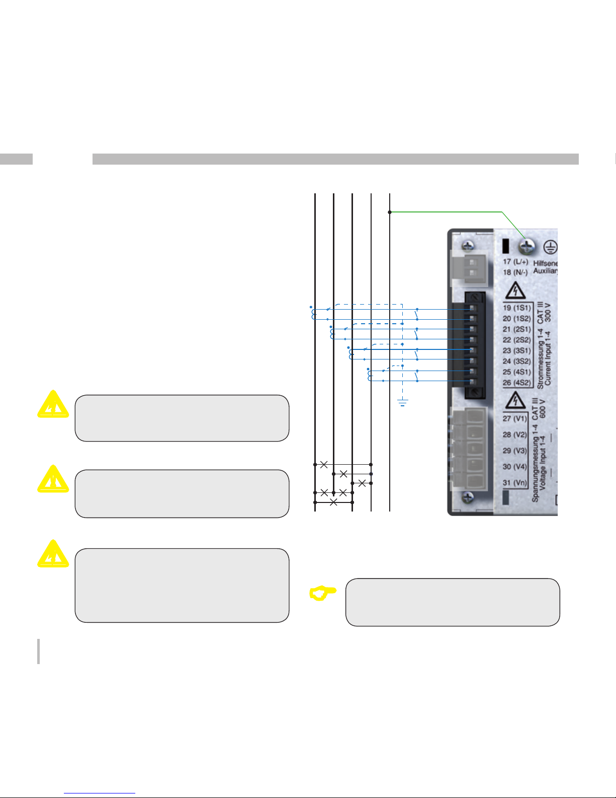
Illu. Connection example, current measurement
using current converter.
Warning!
The UMG508 is not suitable for the
measurement of direct voltages.
Warning!
The current measurement inputs are
dangerous to touch.
m
c
c
A connection diagram does not have
to be configured for meaurement inputs V4 and I4.
C
S1
S2
L1 N PEL3L2
S1
S2
S1
S2
S1
S2
Page 25
25
UMG 508
Current converter connections!
The secondary connections of the current converter must be short-circuited
to these before the electricity cables
are disconnected from the UMG508!
If a test switch is available which automatically shorts the secondary current
converter lines, it is sufficient to set
them to the "test" extradata, as long as
the short-circuiters have been checked
beforehand.
Open current converters!
Extreme contact danger due to voltage
peaks can occur on current converters
that are operated open on the secondary side!
For "anti-open current converters", the
winding isolation is calculated so that
the current converters can be operated
open. However, these current converters are also dangerous to touch if they
are operated open.
cc
Current Direction
The current direction can corrected on the device or individually using the available serial interfaces for each phase.
In the case of incorrect connection, subsequent
reconnection of the current converter is not necessary.
Page 26
26
UMG 508
Total current measurement
If the current is measured using two current
converters, the total transfer ratio of the current converters must be programmed in the
UMG508.
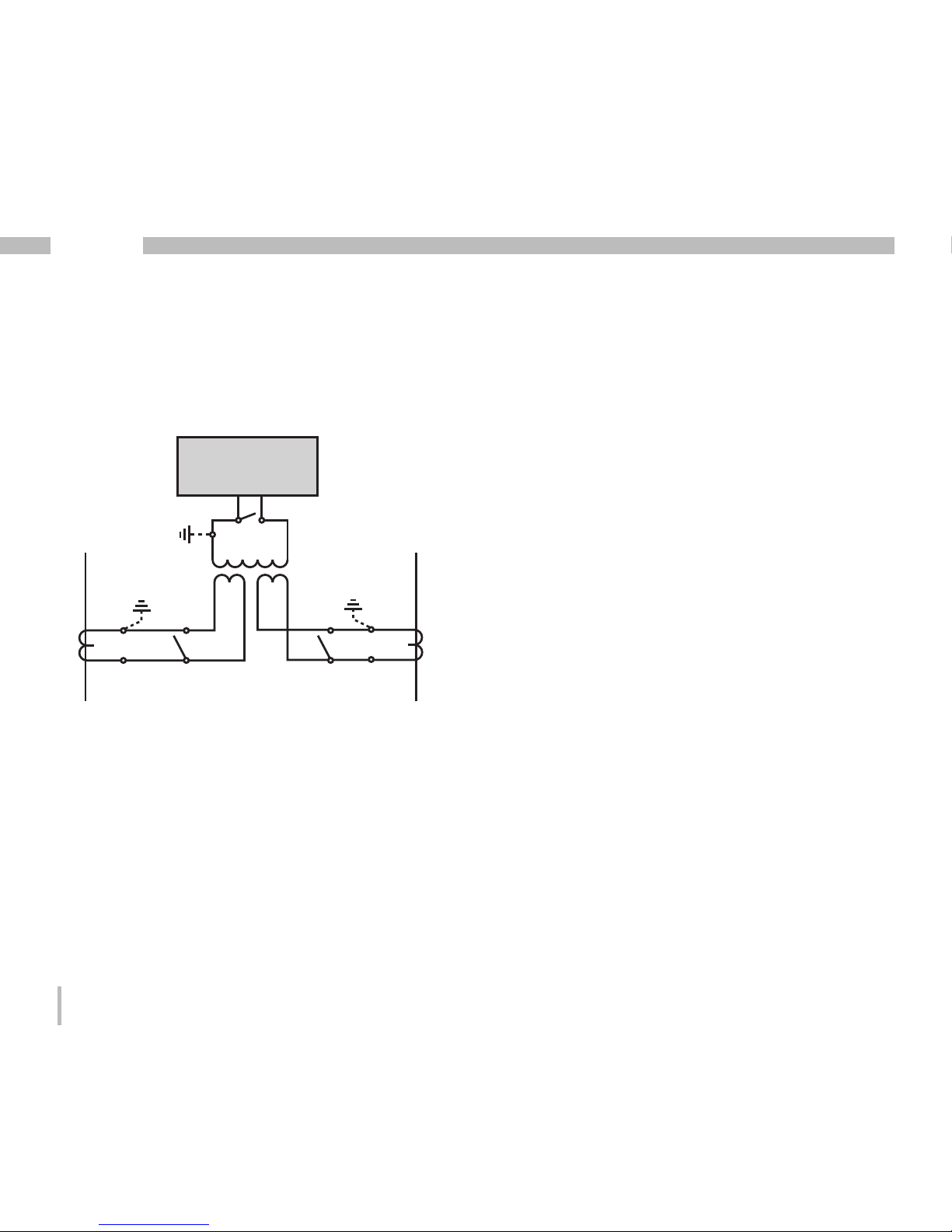
Illu. Example, current measurement using a total
current converter.
Example
The current measurement takes place using
two current converters. Both current converters have a transfer ratio of 1000/5A. The total
measurement is carried out with a 5+5/5A total
current converter.
The UMG508 must then be set as follows:
Primary current: 1000A + 1000A = 2000A
Secondary current: 5A
UMG
S2
I
S
1
P1
P2
Einspeisung 1
Supply 1
Einspeisung 2
Supply 2
1P1
1P2
(K)
(L)
(k)
(l)
1S
2
1S1
1S1 1S2 2S1 2S2
2S1
2S2
(k)
(l)
(K)
(L)
2P
1
2P2
Verbraucher A
Consumer A
Verbraucher B
Consumer B
Page 27
27
UMG 508
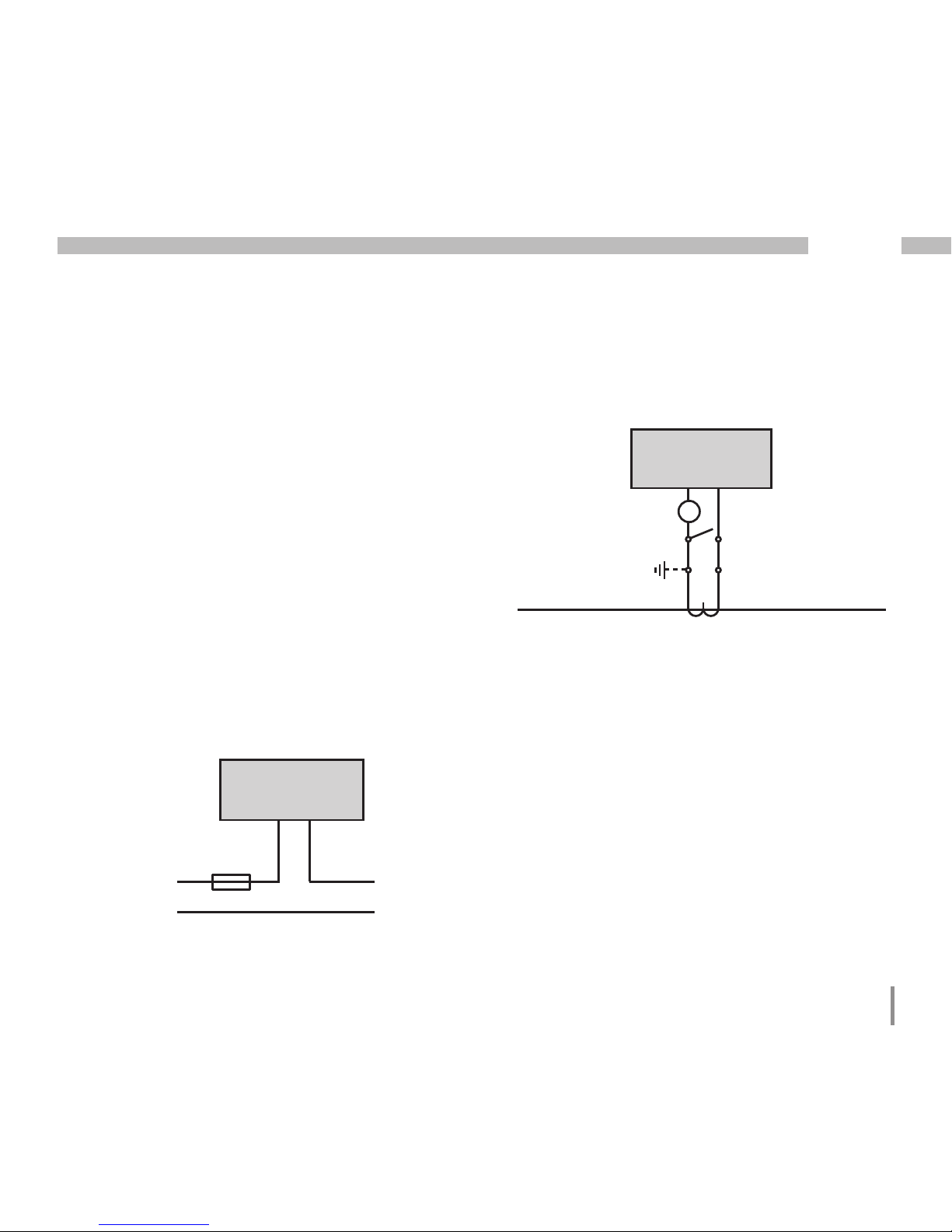
Illu. Example, current measurement with an additional ampere meter.
Ampere meter
If you do not want to measure the current with
the UMG508 alone, but also with an additional
ampere meter, the ampere meter must be switched in series to the UMG508.
Illu. Example, direct current measurement.
Direct measurement
Nominal currents up to 5A can also be directly
measured with the UMG508.
Under consideration that the direct measurement will be carried out for the current only in
three phase 4 wire systems with mains voltage till
• 127V/220V (300V CAT III) according UL
and three phase 3 wire systems with mains
voltage till
• 277V (300V CAT III) according UL
Due to the fact that the UMG508 does not
have integrated protection for the current
measurement, this protection must be foreseen in the installation.
UMG
S2
I
S
1
Einspeisung
Supply
Verbraucher
Consumer
A
(k)S
1 S2(l)
P
2(L)(K)P1
UMG
S2
I
S
1
Einspeisung
Supply
Verbraucher
Consumer
5A Typ C
Page 28
28
UMG 508
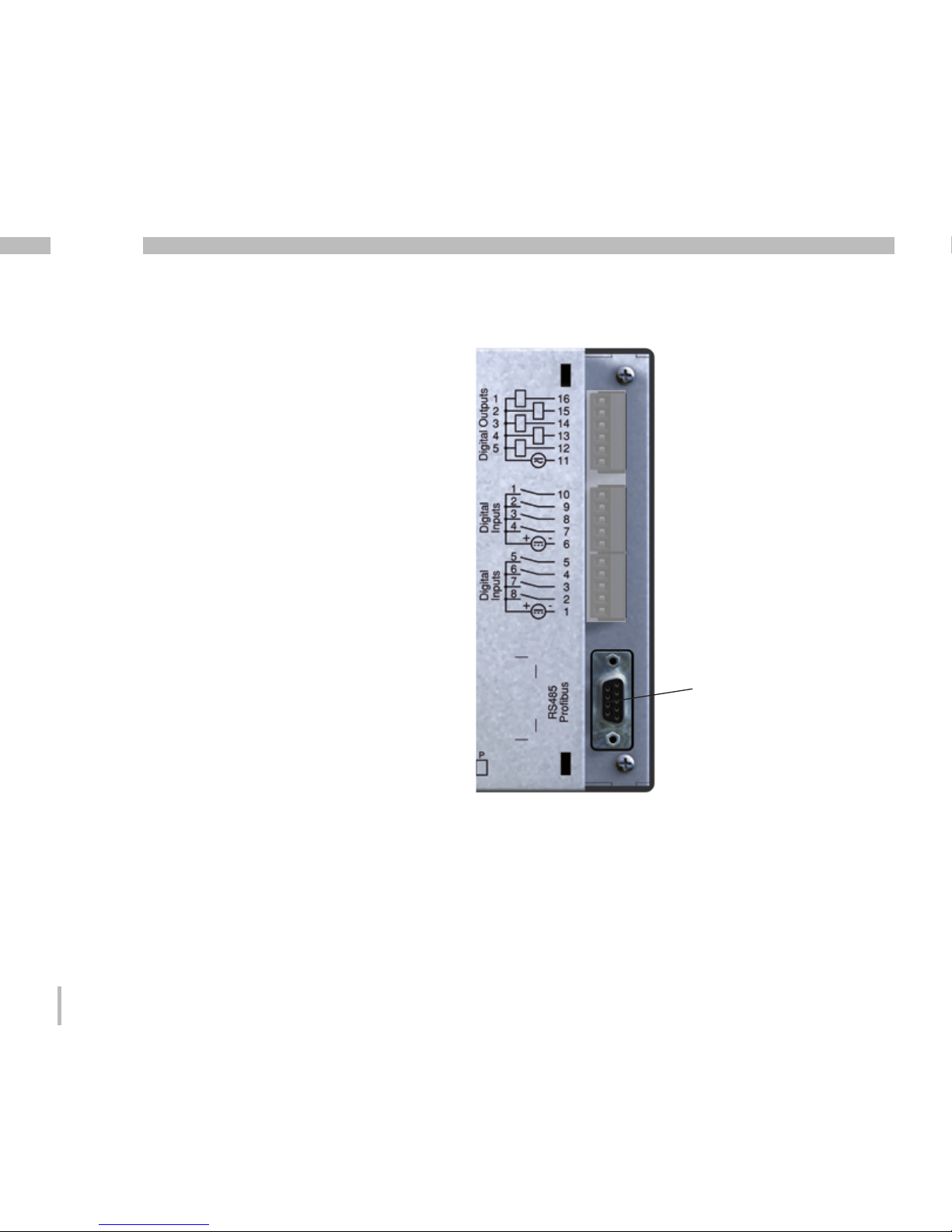
RS485
The RS485 interface is designed as a 9-pole
DSUB socket on the UMG508.
On this interface, the UMG508 supports the following selection of protocols:
• Modbus RTU
• Profibus DP V0 Slave
For connection, we recommend a 9-pin profibus
(modbus) plug e.g. the company Phoenix, type
„SUBCON-Plus-ProfiB/AX/SC“ with the article
number 2744380 (Janitza article no. 13.10.539).
Illu. UMG508 with DSUB socket for the RS485
interface.
DSUB socket
for Modbus
or Profibus.
Page 29
29
UMG 508
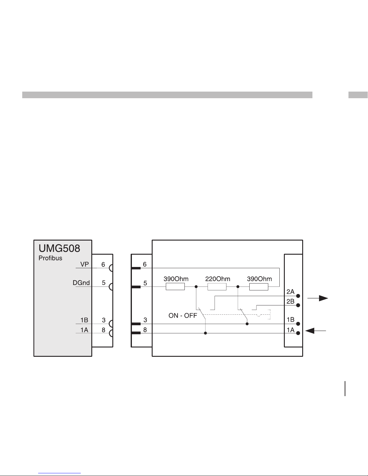
Connection of Bus Lines
The incoming bus line is connected to clamps
1A and 1B. The bus line for the next device in
the line is connected to clamps 2A and 2B. If
there is no further device in the line, the bus line
has to be terminated with resistors (switch to
ON).
In switch extradata ON, clamps 2A and 2B are
switched off for the continuing bus line.
Illu. Profibus plug with terminating resistors.
Profibus- (Modbus)-Stecker (extern)
Profibus (Modbus) connector (external)
Terminating resistors
Other
profibus
stations
Screw-type terminals
D-sub,
9 pin,
socket
D-sub,
9 pin,
connec-
tor
Page 30
30
UMG 508
Shields
A twisted, shielded cable is foreseen for connections using the RS485 interface.
• Ground the shields of all cables leading to the
cabinet at the cabinet entry point.
• Connect the shield extensively and with
good conductivity with a low external voltage
ground.
• Intercept the cable mechanically above
the ground clip in order to avoid damages
caused by cable movements.
• Use suitable cable insert guides, such as PG
glands, to guide the cable into the switch cabinet.
Cable type
The cables used must be suitable for an environmental temperature of at least 80°C.
Recommended cable types:
Unitronic Li2YCY(TP) 2x2x0.22 (Lapp cable)
Unitronic BUS L2/FIP 1x2x0.64 (Lapp cable)
Maximum cable length
1200m at a Baud rate of 38.4k.
Illu. Shielding arrangement at cabinet entry
point.
Cable
Strain relief
Cable shielding braid.
Grounding clip
Low external voltage
ground.
Terminal resistors
The cable is terminated with resistors (120Ohm
1/4W) at the beginning and end of a segment.
The UMG508 does not have any terminal resistors.
C
For the wiring of the Modbus connection, CAT cables are not suitable.
Please use the recommended cables.
Page 31

31
UMG 508
Bus structure
• All devices are connected in a bus structure
(line).
• In one segment, up to 32 participants can be
switched together.
• The cable is terminated with resistors at the
beginning and end of a segment.
• Repeaters (power boosters) must be used
with more than 32 participants in order to
connect the individual segments.
• Devices with terminated resistor have to be
supplied.
• We recommend to install the master UMG at
the end of the segment.
• In case that the master UMG with terminated
bus resistor will be removed, the bus is not
under operation.
• In case that slave UMG with terminated bus
resistor will be removed or is not switched
on, the bus is can be unstable.
• UMGs which have no termination can be replaced without any interruption of the bus.
Page 32

32
UMG 508
Ethernet
The network settings for the Ethernet are specified by the network administrator and set accordingly on the UMG508.
If the network settings are not known, the patch
cable may not be plugged into the UMG508.
Ethernet connection
Patch cable
Warning!
Incorrect nework settings can cause
faults in the network!
m
Page 33

33
UMG 508
Illu. Connection example; UMG508 and PC
need a fixed IP address.
Illu. Connection example; UMG508 and PC are
automatically allocated the IP address from a
DHCP server.
DHCP
Server
Switch
PC UMG508
Patch cable
PC
UMG508
Patch cable
Switch
Illu. Connection example; direct connection
between the UMG508 and PC using a twisted
patch cable (art. no. 08.01.505)
PC
UMG508
Patch cable
(twisted)
Page 34

34
UMG 508
Digital outputs
The UMG508 has 5 digital outputs. These outputs are separated galvanically from the analysis electronics using optocouplers. The digital
outputs have a common reference.
• The digital outputs can switch AC and DC
loads.
• The digital outputs arenotshort-circuit proof.
• Connected lines that are longer than 30m
must be laid with shields.
• External auxiliary power is necessary.
~
Illu. Digital outputs connection.
Page 35

35
UMG 508
Illu. Connection of two relays to digital outputs
4 and 5.
16
K1 K2
24V
AC
External
auxiliary power
UMG508
Digital outputs 1-5
Digital Outputs 1-5
12
Digital
Output 5
13
Digital
Output 4
14
Digital
Output 3
15
Digital
Output 2
Digital
Output 1
~~
11
Page 36

36
UMG 508
Digital Inputs
The UMG508 has 8 digital inputs. The digital inputs are divided into two groups, each with 4
inputs. Each group has a common reference.
Illu. Example for the connection of external contacts S1 and S2 to the digital inputs 1 and 2.
24V
DC
-
+
External
auxiliary power
S1
S2
UMG508
Digital Inputs 1-4
Digital Inputs 1-4
3.9V
4k
10
Digital
Input 1
Digital
Input 3
Digital
Input 2
Digital
Input 4
3.9V
3,9V
3,9V
4k
4k
4k
9
8
7
6
-
+
-
+
Illu. Example for the connection of digital inputs.
Page 37

37
UMG 508
S0 impulse input
You can connect an S0 impulse generator in accordance with DIN EN62053-31 to each digital
input.
You require an external auxiliary voltage with an
output voltage in the range of 20 .. 28V DC and
a resistor with 1.5kOhm.
Illu. Example for the connection of an S0 impulse generator to digital input 1.
24V
DC
-
+
External
auxiliary voltage
UMG508
Digitale Inputs 1-4
Digital Inputs 1-4
3.9V
4k
10
Digital
Input 1
Digital
Input 3
Digital
Input 2
Digital
Input 4
3.9V
3.9V
3.9V
4k
4k
4k
9
8
7
6
1.5k
S0
Impulse
generator
Page 38

38
UMG 508
Operation
The UMG508 is operated using six function
keys.
The six keys are allocated different functions
depending on the context:
• Selection of measurement value displays.
• Navigation within the menu.
• Processing the device settings.
Function key labeling
Display titles
Measurement values
Function keys
Page 39

39
UMG 508
Measurement value displays
Main values
You can use keys 2 and 5 to browse between
the main values of the measurement value displays.
Display
Configuration
Display
Pointer dia-
gram
Display
"Home“
Display
Voltages L-N
Auxiliary values
You can use keys 3 and 4 to browse between
the auxiliary values of a measurement value display.
Display
Voltage L-N
Display
Voltages L-L
Main values
Auxiliary values
Page 40

40
UMG 508
"Home“ measurement value display
Once the network returns, the UMG508 starts
with the "Home“ measurement value display.
This measurement value display contains the
device names and an overview of important
measurement values. The device name consists
of the device type and serial number upon delivery.
Using the "Home - Key 1“, you come
out of the measurement value displays for the main values directly to
the first "Home" measurement value
display.
Page 41

41
UMG 508
Select measurement value display
You want to change to a measurement value
display with main values.
• Use the function keys 2 and 5 to browse between the measurement value displays of the
main values.
• With function key 1 (Home), you always access the first measurement value display.
Display
Voltage L-N
Display
Voltages L-L
You want to change to a measurement value
display with auxiliary values.
• Select the measurement value display with
the main values.
• Select the measurement value display with
function keys 3 and 4 for the auxiliary values.
Example: selection of auxiliary value voltage.
Page 42

42
UMG 508
Call up additional information
• Browse with keys 2 to 5 to the required measurement value display.
• Activate the measurement value selection
with key 6 (selection).
• Select the required measurement value with
keys 2 to 5.
• The background colour for the measurement
value changes from grey to green. The additional information is shown in a blue window.
• End the process with key 1 (ESC) or select
another measurement value with keys 2 to 5.
Page 43

43
UMG 508
Delete min/max values individually
• Use keys 2 to 5 to browse to the required
measurement value display.
• Activate the measurement value selection
with key 6 (selection).
• Select the required minimum and maximum
value with keys 2 to 5.
• The background colour for the measurement
value changes from grey to green. The point
with the date and time of occurence is shown
in an additional blue window.
• You can now delete the selected min or max
value with key 6 (reset).
• End the process with key 1 (ESC) or select
another min/max value with keys 2 to 5.
C
The date and time for the min/max values are shown in UTC time (coordinated world time).
Page 44

44
UMG 508
List of transients
Recognized transients are listed in the transients list.
• The transients list consists of 2 pages.
• Transients 1 to 8 are listed on page 1 and 9
to 16 on page 2.
Display transients
• Go to the transients list with key 6 „selection“.
• Select a transient with keys 3 and 4.
• Allow to the transients to be presented graphically with key 6.
• Show or hide the legends with key 6 „Legends“.
• You can exit the graphic presentation of the
transients with key 1.
Transient voltages are quick, impulsive
transient oscillation processes in electrical networks.
Transient voltages are not predictable
with respect to time and have a limited
period.
Transient voltages are caused by the
effects of lighting, by switching operations or by triggered fuses.
C
Page 45

45
UMG 508
List of events
Recognized events are listed in the events list.
• The events list consists of 2 pages.
• Events 1 to 8 are listed on page 1 and events
9 to 18 on page 2.
Display incident
• Go to the events list with key 6 „Selection“.
• Select an incident with keys 3 and 4.
• Allow the incident to be graphically presented with key 6.
• Show or hide the legends with key 6 „Legends“.
• You can leave the graphic presentation of the
incident with key 1.
Events are limit value violations of effective current and voltage values.
C
Page 46

46
UMG 508
Configuration
The supply voltage must be connected for configuration of the UMG508.
Apply supply voltage
• The level of supply voltage for the UMG508
can be taken from the label.
• After applying the supply voltage, a startup
screen appears on the display. Approximately ten seconds later, the UMG508 changes to
the first „Home“ measurement value display.
• If a display does not appear, check whether
the applied supply voltage is within the nominal voltage range.
Warning!
Supply voltages that do not correspond with the label details can lead to
incorrect functions and damage to the
device.
c
Illu. Example of "Home“ measurement value.
Page 47

47
UMG 508
Configuration menu
Once the network returns, the „Home“ measurement value display is found on the start page.
• Browse to the menu configuration with key 1.
If you are in a measurement value display for
main values, you use
• key 1 - „Home“ to directly access the first
„Home“ measurement display.
• Use key 1 to browse to the menu configuration.
Language
You can set the language for the measurement
value displays and menus directly in the "configuration" menu.
There are different languages to select between.
The preset language in the factory is "English".
Display
Configuration
Display
"home“
Main values
Illu. Example configuration of "languages".
Page 48

48
UMG 508
Communication
The UMG508 has an Ethernet and a RS485 interface.
Ethernet (TCP/IP)
Select the type of address allocation for the
Ethernet interface here.
DHCP mode
• Off- IP address, Netmask and Gateway are
specified by the user and set directly on the
UMG508. Select this mode for simple networks without a DHCP server.
• BOOTP - BootP permits the fully automatic
integration of a UMG508 in an existing network. BootP is an older protocol and does
not have DHCP's extent of functions.
• DHCP- Upon starting, the UMG508 automatically collects the IP address, the Netmask
and the Gateway from a DHCP server.
Factory pre-setting:DHCP
The UMG508 may only be connected
to the Ethernet after coordinating with
the network administrator!
m
Page 49

49
UMG 508
RS485
You can specify the protocol, the device address
and the Baud rate for operating the RS485 interface.
Protocol
Selection options:
• Modbus Slave
• Modbus Master/Gateway
• Profibus DP V0
• BACnet (Option)
Factory pre-setting:
Modbus Master/Gateway
Device address
Setting range: 0 - 255
Factory pre-setting: 1
Baud rate
Setting range: 9.600, 19.200, 38.400, 57.600,
115.200, 921.600 kbps
Factory pre-setting: 115.200 kbps
Page 50

50
UMG 508
Measurement
Configure here:
• The measurement converters for the current
and voltage measurement.
• The record of transients.
• The recording of events.
• The rated frequency.
Page 51

51
UMG 508
Rated frequency
For measuring and calculating the meaurement
values, the UMG508 requires the Rated frequency of a.c. systems.
The UMG508 is suitable for measurements in
networks with a rated frequency in the range of
40Hz to 70Hz.
The rated frequency can be specified by the
user or automatically detected by the device.
• Auto- Factory pre-setting. The rated frequency is measured.
• 50Hz- The rated frequency is set to 50Hz.
The rated frequency is not measured.
• 60Hz- The rated frequency is set to 60Hz.
The rated frequency is not measured.
Automatic frequency detection
A voltage (V-Vref) larger than 10Veff must be
applied on at least one of the voltage measurement inputs for the automatic detection of frequency by the UMG508.
If a sufficient measurement voltage is not applied, the UMG508 can not detect the rated frequency and a measurement can therefore not
be carried out.
Page 52

52
UMG 508
Nominal voltage
The nominal voltage specifies the value which
• transients,
• events and automatic graphic scaling refer
to.
Setting range: 0 .. 1,000,000 V
Factory pre-setting: 230 V
For example, you can also select the primary
voltage as nominal voltage.
Voltage converter
You can allocate the main meaurement and the
auxiliary measurement voltage converter relations.
You select the setting 400 V / 400 V for measurements without a voltage converter.
Setting range:
Primary 1 .. 999,999 V
Secondary 1 .. 400 V
Factory pre-setting:
Primary 400 V
Secondary 400 V
Page 53

53
UMG 508
Illu. Example for voltage measurement in a 3
phase 4 conductor network.
A connection diagram has to be configured for the measurement inputs V4
and I4.
C
Connection diagram for voltage
measurement
For the voltage measurement, you can select
between the following connection diagrams:
3p4w - 3 phase 4 conductor
3p4wu - 3 phase 4 conductor
3p3w - 3 phase 4 conductor
For networks without a neutral
conductor under symmetric load.
3p3wu - 3 Phasen 3 Leiter
For networks without a neutral
conductor under symmetric load.
3p5w - 3 Phasen 4 Leiter
Measurement of an additional
measuring point.
1p2w - 1 phase 2 conductor (180°)
Factory pre-setting: 3p4w
Page 54

54
UMG 508
Current converter
You can allocate both the main measurement
and auxiliary measurement current converter
relations.
Select setting 5/5A for direct measurement of
currents.
Setting range:
Primary 1 .. 999,999 A
Secondary 1 .. 5 A
Factory pre-setting:
Primary 5 A
Secondary 5 A
Nominal current
The nominal current specifies which value
• overcurrent,
• current transients,
• and automatic graphics scaling
refer to.
Setting range: 0 .. 1,000,000 A
You can only set the nominal values for
measurement of the K-Factor and TDD
using GridVis.
C
Page 55

55
UMG 508
Illu. Example for current measurement using 3
current converters in a 3 phase 4 conductor network.
A connection diagram does not have
to be configured for measurement inputs V4 and I4.
C
Connection diagram for current
measurement
You can select between the following connection diagrams for current measurement:
3p4w - 3 phase 4 conductor, 3 current conv.
3p5w - 3 phase 4 conductor, 4 current conv.
The fourth current transformer can be
used for measuring the neutral
conductor e.g.
3p2i - 3 phase 4 conductor, 2 current conv.
For networks under symmetric load.
3p2i0 - 3 phase 3 conductor, 2 current conv.
Aron connection for networks without
a neutral conductor. The third current
will be calculated.
1p2i - 1 Phasen 2 Leiter, 2 Stromwandler
Factory pre-setting: 3p4w
Page 56

56
UMG 508
Transients
Transient voltages are rapid, impulsive transient oscillation processes in electrical networks.
Transient voltages are not predictable with respect to time and last for a limited period.
Transient voltages are caused by the effects of
lighting, due to switching operations or the triggering of fuses.
• The UMG508 recognizes transients that are
longer than 50µs.
• The UMG508 monitors the voltage measurement inputs on transients.
• Transient monitoring can be set per phase.
• There are two independent criteria for recognizing transients.
• If a transient has been recognized, the wave
shape is saved in a transient recording.
• If a transient has been recognized, the limit
value is automatically increased by 20V, both
in automatic and manual modes. This automatic increase of the limit value fades within
10 minutes.
• If another transient is recognized within the
next 60 seconds, this transient is recorded
with 512 points.
• You can display recorded transients with the
GridVis incident browser.
Page 57

57
UMG 508
Mode (delta)
If the difference of two neighbouring scanning
points exceeds the set limit value, a transient is
recognized.
• Off- Transient monitoring is switched off.
• Automatic- Factoring pre-setting. The limit
value is calculated automatically and is 0.2175
times the current 200ms effective value.
• Manual- Transient monitoring uses the adjustable limit value under "Trns U“.
Accept L2-L4
Transient monitoring can be set per phase. You
can accept settings from phase L1 into phases
L2, L3 and L4.
• No - The L1 phase settings are not transferred
to the stages L2, L3 and L4.
• Yes- The settings from phase L1 are taken
over into phases L2, L3 and L4.
Mode (absolute)
If a scanning value exceeds the set limit value, a
transient is recognized.
• Off- Transient monitoring is switched off
• Automatic- Factory pre-setting. The limit va-
lue is automatically calculated and is 110% of
the current 200 ms effective value.
• Manual- Transient monitoring uses the adjustable limit value under "Peak U“.
Page 58

58
UMG 508
Events
Events are threshold value violations of set
threshold values for current and voltage.
Here, threshold values are compared with the
full wave effective values for current and voltage from the measurement channels. The event
record consists of a mean value, a minimum or
maximum value, a start time and an end time.
• Monitoring of the threshold values can be
switched off (Off/Manual).
• Threshold values must be set as a percentage
of the nominal value.
• Threshold values can be set for excess voltage, undervoltage and overcurrent.
• An event is triggered if in the course of the prerun period there is an uninterrupted threshold
value violation. An event is ended if there are
no threshold value violations in the course of
the after-run period.
• If an event has occurred, the corresponding
measurement value is recorded with the set
pre-run and after-run periods (respectively
0..1000 full waves).
• Event records are configured with the GridVis
and displayed with the event browser.
Limit value
Measured
value
Vollwelleneffektivwert
Limit value
violations
before the
lead time
End time
Limit value violations
before the follow-up time
Event
Follow-up timeLead time
Start time event
(Trigger time)
Event record
Pre-run
After-run
Fig. Shows the full wave effective values for an
event.
Page 59

59
UMG 508
Voltage
Drop
A drop in voltage is set in % of the nominal voltage.
Overvoltage
The overvoltage is set in % of the nominal voltage.
Current
Overcurrent
The rapid increase of current is set in % of the
nominal current.
Accept L2-L4
Monitoring of events can be set per phase. You
can accept settings from phase L1 into phases
L2, L3 and L4.
• No- Settings from phase L1 are not taken
over into phases L2, L3 and L4.
• Yes- The settings from phase L1 are taken
over into phases L2, L3 and L4.
Follow-up time
The follow-up time can only be set with
GridVis.
Factory pre-setting: 0
C
Preparation time
The preparation time can only be set
with GridVis.
Factory pre-setting: 0
C
Page 60

60
UMG 508
Display
Brightness
The brightness level of the background illumination can be adjusted. The brightness level set
here is used during operation of the UMG508.
Setting range: 0 .. 100%
Factory pre-setting: 70%
(0% = dark, 100% = very bright)
Standby
This refers to the time before the brightness
changes to "standby brightness".
Setting range: 60 .. 9999 seconds
Factory pre-setting: 900 seconds
Standby brightness
This refers to the brightness level changed to
after the end of the standby time. The standby
time is restarted by using keys 1-6.
Setting range: 0 .. 60%
Factory pre-setting: 40%
Screensaver
The screensaver prevents a screen on the LCD
from "sticking" if the screen does not change for
a longer period of time.
Setting range: yes, no
Factory pre-setting: yes
Presentation
You can specify the speed at which new measurement values should appear on the measurement value displays.
Setting range: fast (200ms),
slow (1s)
Factory pre-setting: fast
Rotate
The measurement value displays are automatically displayed in sequence. The configuration
displays are not affected by this.
Setting range: yes, no
Factory pre-setting: no
Page 61

61
UMG 508
The service life of the background illumination extends if the brightness
of the background illumination is kept
lower.
Transition time
You can set the time between automatic transition to the next measurement value display.
Setting range: 0 .. 255 seconds
Factory pre-setting: 2 seconds
C
Page 62

62
UMG 508
System settings
Display of system settings specific to the device.
Firmware version
Device serial number
Fixed device MAC address
Set IP address
Set Gateway address
Date and time
Set password
Reset settings
Illu. Example for the display of system settings.
C
You cannot configure the date and time
directly on the device.
Settings for time synchronization and
the date and time can only be made
using GridVis.
Page 63

63
UMG 508
Forgotten password
If you have forgotten the password, you can
only delete the password using the "GridVis“
software.
In order to do this, connect the UMG508 with
the PC using a suitable interface. Further information can be found in the GridVis assistant.
Password
The user can block access to the configuration
with a password. Changing the configuration directly on the device is then only possible after
entering the password.
The password consists of a 6 digit combination
of numbers.
Setting range: 1-999999 = with password
000000 = without password
A password (000000) is not programmed in the
factory.
• In order to change a set password, you must
know the current password.
• Note any changed password.
• If you do not want a password request anymore, enter "000000" as a password.
Page 64

64
UMG 508
Delete minimum and maximum values
You can delete all minimum and maximum values in the UMG508 simultaneously.
How to delete the individual minimum and maximum values is described in the chapter "individually deleting min. and max. values".
Delete all minimum and maximum values.
• Select "yes" with key 3
• Confirm with key 6.
• The message "executed" appears in the line all minimum and maximum values have been
deleted.
Page 65

65
UMG 508
Delete power meters
You can delete all power meters in the UMG508
at the same time.
A selection of certain power meters is not possible.
• Select with key 3 "yes“
• Confirm with key 6.
• The message "executed" appears in the line all power meters have been deleted.
Prior to commissioning potential production dependant contents of the
energy counter, min/max values and
records have to be deleted.
C
Page 66

66
UMG 508
Delivered condition
All settings such as the configuration and recorded data are reset to the factory pre-settings or
deleted. Entered release codes are not deleted.
• Select with key 3 "yes“
• Confirm with key 6.
• The message "executed" appears in the line the delivered condition is reinstored.
Restart
The UMG508 restarts all programs.
• Select with the key 3 "yes“.
• Confirm with key 6.
• The message "executed" appears in the line
- all programs have been restarted.
Page 67

67
UMG 508
Colors
Selection of colors for the presentation of current and voltage in the graphic presentations.
Page 68

68
UMG 508
Extensions
Under "Extensions“ you can subsequently release charged functions and show the status of
Jasic programs.
Page 69

69
UMG 508
Release
The UMG508 contains chargeable functions
that can be subsequently released.
List of release functions:
• BACnet
• EMAX
You receive the release code from the manufacturer. The manufacturer needs the device serial
number and the name of function to be released.
In order to release the function, you enter the 6
digit release code in the respective line.
Please note that the release code is only valid
for one device.
Page 70

70
UMG 508
Jasic status
Up to 7 specific customer Jasic programs (1-7)
and one recording can run in the UMG508.
The Jasic programs can adopt the following statuses:
• Stopped
• Running
You cannot change the status of Jasic programs
on the device.
Page 71

71
UMG 508
Initialization
Applying the supply voltage
• The level of supply voltage for the UMG508
can be taken from the label.
• After applying the supply voltage, a startup
screen appears on the display. Around ten
seconds later, the UMG508 changes to the
first measurement value display.
• If no display appears, you must check whether the supply voltage is within the nominal
voltage range.
Warning!
Supply voltages that do not correspond with the details on the type label
can lead to malfunctions and damage
to the device.
m
Page 72

72
UMG 508
Rotary field direction
Check the direction of the voltage rotary field on
the measurement value display of the UMG508.
A "right" rotary field is usually available.
Presentation of the phase sequence according
to the rotary field direction.
UL1-UL2-UL3 = right rotary field
UL1-UL3-UL2 = left rotary field
Apply measurement voltage
• Voltage measurements in networks with
nominal voltages above 346VAC against
ground must be connected using a voltage
converter.
• After connection of the measurement voltages, the measurement values displayed by
the UMG508 for voltages L-N and L-L must
match those at the voltage measurement input.
• If a voltage converter factor is programmed,
this must considered upon comparison.
Warning!
The UMG508 is not suitable for measuring DC voltages.
m
Page 73

73
UMG 508
Applying measurement current
The UMG508 is designed for the connection of
../1A and ../5A current converters.
Only AC currents, and not DC currents, can be
measured using the current measurement inputs.
Short-circuit all current converter outputs except one. Compare the currents displayed by
the UMG508 with the applied current.
The current displayed by the UMG508 must
match the input current under consideration of
the current converter transfer relation.
The UMG508 must display approx. zero amperes in the short-circuited current measurement inputs.
The current converter ratio is set to 5/5A in the
factory and may have to be adapted to the current converter used.
Warning!
Voltages and currents outside of the
authorized measurement range can
destroy the device.
m
Voltages are shown with long pointers in the
pointer diagram, and currents with shorter
pointers.
Current
Voltage
Sign
Reactive power
• positive (+) with inductive load,
• negative (-) with capacitive load.
Phase angle (U/I)
• positive (+) with capacitive load,
• negative (-) with inductive load.
Page 74

74
UMG 508
Voltage and current only have
a minor difference in the phase.
Voltage and current have a
difference of approximately
180° in the phase.
Pointer diagram, examplel 1
Primarily ohmic load.
Pointer diagram, example 2
Primarily ohmic load.
• The current measurement input is allocated
to the right voltage measurement input.
• In this current measurement, the connections
k and l are swapped over or there is a return
feed into the supplier network.
• The current measurement input is allocated
to the right voltage measurement input.
Page 75

75
UMG 508
Checking communication
The UMG508 counts all received (RX), all sent
(TX) and all faulty data packages.
In the ideal case, the number of errors shown in
the error column is zero.
Reset
You can delete the counters for the data packages with key 6.
The start time for the recount is reset.
Checking the power measurement
Short-circuit all current converter outputs except one and check the displayed power outputs.
The UMG508 may only display one power output in the phase with the current converter input
that is not short-circuited. If this does not apply,
please check the connection of the measurement voltage and measurement current.
If the amount of effective power is correct but
the sign of effective power is negative, this may
have two causes:
• Connections S1(k) and S2(l) are mixed up on
the current converter.
• Effective power is returned to the network.
In the pointer diagram, voltages are shown with
the longer pointers and currents with shorter
pointers.
Page 76

76
UMG 508
Metering range exceedance
(overload)
Metering range exceedances are displayed for
as long as they are present and cannot be acknowledged. A metering range is exceeded if
at least one of the four voltage or current measuring inputs is outside of its specified metering range.
Limit values for metering range exceedance:
(200 ms rms values):
I = 7.4 Arms
UL-N = 600 Vrms
Display of the metering range exceedance
in the voltage circuit L2 and in the current
circuit of the 4th phase (I4).
Page 77

77
UMG 508
Device master file
The device master file, abbreviated with GSD
file, describes the Profibus characteristics of the
UMG508. The GSD file is required by the PLC
configuration program.
The device master file for the UMG508 has the
file name "U5080C2C.GSD“ and is contained on
the data carrier supplied with the delivery.
1)
Global variables are variables that are defined by
the user in Jasic and are provided to each interface
in the UMG508.
Profibus profile
A Profibus profile contains data to be exchanged
between a UMG and an SPS. Four Profibus profiles are pre-configured in the factory.
With a Profibus profile, you can:
• call-up measurement values from the UMG,
• set the digital outputs in the UMG,
• request the status of the digital inputs in the
UMG.
Each Profibus profile can contain a maximum of
127Bytes. You can apply further Profibus profiles if more data has to be transferred.
• Each Profibus profile has a profile number.
The profile number is sent by the PLC to the
UMG.
• You can directly process 16 Profibus profiles
with GridVis (profile numbers 0..15).
• Additional Profibus profiles (profile numbers
16..255) can be applied using Jasic programs.
• Factory pre-configured Profibus profiles can
be subsequently changed.
Variable definition
All system variables and global variables
1)
can
be scaled individually and converted into one of
the following formats:
• 8, 16, 32Bit integer with and without sign.
• 32 or 64Bit float format.
• Big or Little Endian.
Big-Endian = High Byte before Low Byte.
Little-Endian = Low Byte before High Byte.
Page 78

78
UMG 508
Illu. Block switch diagram for data exchange between PLC and UMG508.
Example
Collect measurement values using Profibus
You must transfer at least one Profibus profile
with GridVis and transfer it to the UMG508.
A Jasic program is not necessary.
Page 79

79
UMG 508
Profibus profile number 1
Byte- Values- Scaling
Index Value type format
1 1 Voltage L1-N Float 1
2 5 Voltage L2-N Float 1
3 9 Voltage L3-N Float 1
4 13 Voltage L2-L1 Float 1
5 17 Voltage L3-L2 Float 1
6 21 Voltage L1-L3 Float 1
7 25 Current L1 Float 1
8 29 Current L2 Float 1
9 33 Current L3 Float 1
10 37 Effective power L1 Float 1
11 41 Effective power L2 Float 1
12 45 Effective power L3 Float 1
13 49 Cosphi (math.) L1 Float 1
14 53 Cosphi (math.) L2 Float 1
15 57 Cosphi (math.) L3 Float 1
16 61 Frequency Float 1
17 65 Effective power total L1-L3 Float 1
18 69 Reactive power total L1-L3 Float 1
19 73 Apparent power total L1-L3 Float 1
20 77 Cosphi (math.) total L1-L3 Float 1
21 81 Effective current total L1-L3 Float 1
22 85 Effective consumption total L1-L3 Float 1
23 89 Ind. Reactive consum. total L1-L3 Float 1
24 93 THD voltage L1 Float 1
25 97 THD voltage L2 Float 1
26 101 THD voltage L3 Float 1
27 105 THD current L1 Float 1
28 109 THD current L2 Float 1
29 113 THD current L3 Float 1
Profibus profile number 0
Byte Value Scaling
Index Value type format
1 1 Voltage L1-N float 1
2 5 Voltage L2-N float 1
3 9 Voltage L3-N float 1
4 13 Voltage L4-N float 1
5 17 Voltage L2-L1 float 1
6 21 Voltage L3-L2 float 1
7 25 Voltage L1-L3 float 1
8 29 Current L1 float 1
9 33 Current L2 float 1
10 37 Current L3 float 1
11 41 Current L4 float 1
12 45 Effective power L1 float 1
13 49 Effective power L2 float 1
14 53 Effective power L3 float 1
15 57 Effective power L4 float 1
16 61 Cosphi (math.) L1 float 1
17 65 Cosphi (math.) L2 float 1
18 69 Cosphi (math.) L3 float 1
19 73 Cosphi (math.) L4 float 1
20 77 Frequency float 1
21 81 Effective power total L1-L4 float 1
22 85 Reactive power L1-L4 float 1
23 89 Apparent power total L1-L4 float 1
24 93 Cosphi (math.) total L1-L4 float 1
25 97 Effective current total L1-L4 float 1
26 101 Effective consumption total L1-L4 float 1
27 105 Ind. reactive consum. total L1-L4 float 1
28 109 THD voltage L1 float 1
29 113 THD voltage L2 float 1
30 117 THD voltage L3 float 1
Page 80

80
UMG 508
Profibus profile number 2 Profibus profile number 3
Byte- Values- Scaling
Index Value type Format
1 1 Effective power L1 Float 1
2 5 Effective power L2 Float 1
3 9 Effective power L3 Float 1
4 13 Effective power total L1-L3 Float 1
5 17 Current L1 Float 1
6 21 Current L2 Float 1
7 25 Current L3 Float 1
8 29 Current total L1-L3 Float 1
9 33 Effective consumption total L1-L3 Float 1
10 37 CosPhi (math.) L1 Float 1
11 41 CosPhi (math.) L2 Float 1
12 45 CosPhi (math.) L3 Float 1
13 49 CosPhi (math.) total L1-L3 Float 1
14 53 Reactive power L1 Float 1
15 53 Reactive power L2 Float 1
16 53 Reactive power L3 Float 1
17 53 Reactive power total L1-L3 Float 1
18 53 Apparent power L1 Float 1
19 53 Apparent power L2 Float 1
20 53 Apparent power L3 Float 1
21 53 Apparent power total L1-L3 Float 1
Byte- Values- Scaling
Index Value type Format
1 1 Effective consumption total L1-L3 Float 1
2 5 Drawn eff. consum. total L1-L3 Float 1
3 9 Supplied eff. consum. total L1-L3 Float 1
4 13 Reactive consumption total L1-L3 Float 1
5 17 Ind. reactive consum. total L1-L3 Float 1
6 21 Cap. reactive consum. total L1-L3 Float 1
7 25 Apparent consumption total L1-L3 Float 1
8 29 Effective consumption L1 Float 1
9 33 Effective consumption L2 Float 1
10 37 Effective consumption L3 Float 1
11 41 Inductive reactive consumption L1 Float 1
12 45 Inductive reactive consumption L2 Float 1
13 49 Inductive reactive consumption L3 Float 1
Page 81

81
UMG 508
Service and Maintenance
The device is subjected to different safety tests
before delivery and marked with a seal. If a device is opened, the safety tests have to be repeated. A guarantee is only provided for unopened devices.
Repair and Calibration
Repair work and calibration can only be undertaken by the manufacturer.
Front film
Cleaning the front film can be done with a soft
cloth and domestic detergent. Acids and products containing acids may not be used for
cleaning.
Battery
The internal clock is fed from the supply voltage.
If the supply voltage fails, the clock is supplied
by the battery. The clock provides the date and
time information, e.g. for recordings, minimum
and maximum values and events.
The expected battery life is at least 5 years at a
storage temperature of +45°C. The typical battery life is 8 to 10 years.
The device must be opened to exchange the
battery. If the device has been opened, a new
safety test is required for safe operation. A guarantee is only provided for unopened devices.
Disposal
The UMG508 can be recycled as electronic
scrap in accordance with the legal regulations.
The fixed, integrated lithium battery must be
disposed of separately.
Firmware update
If a firmware update has to be carried out for
your UMG508, you can do this with the GridVis
software included in the delivery.
Service
Should any questions arise that are not described in this handbook please contact the manufacturer directly.
We will require the following compulsory details
from you for processing:
-Device name (refer to label),
-Serial number (refer to label),
-Software release (refer to measurement value
display),
-Measurement voltage and supply voltage,
-Precise error description.
Page 82

82
UMG 508
Possible error
None Display.
None Current dis-
play.
Displayed current is
too high or low.
Displayed voltage is
too low or high
Displayed voltage is
too light.
Cause
External fuse for the supply voltage has triggered.
The measurement voltage is not
connected.
The measurement current is not
connected.
Current measurement is in the
wrong phase.
Current converter factor is incorrectly programmed.
Measurement in the wrong phase.
Voltage converter is incorrectly
programmed.
Measurement range exceeded.
The voltage peak at the measurement input has been exceeded due to harmonics.
Remedy
Replace fuse.
Connect measurement voltage.
Connect measurement current.
Check connection and correct if
necessary.
Read current converter transfer
ratio on the current converter and
program it.
Check connection and correct if
necessary.
Read voltage converter transfer
ratio on the voltage converter and
program it.
Use a voltage converter.
Warning!It is necessary to make
sure that the measurement inputs
are not overloaded.
Procedure in case of errors
Page 83

83
UMG 508
Possible errors
Metering range exceedance (overload)
Effective power is
too high or low.
Effective power-
receipt/supply are
mixed up.
Cause
Voltage or current input out
of range (see chapter metering range exceedance)
The programmed current
converter transfer ratio is
wrong.
The current path is allocated
to the wrong voltage path.
The programmed voltage
converter transfer ratio is
wrong.
At least one current converter connection is mixed up.
A current path is allocated to
the wrong voltage path.
Remedy
Check and correct the connection if
necessary.
Use suitable voltage or current transformers.
Read and program the current or voltage
transformer ratio on the transformer.
Read and program the current converter transfer ratio on the current converter.
Check the connection and correct if
necessary.
Read and program the current converter transfer ratio on the current converter.
Check and correct the connection if
necessary.
Check and correct the connection if
necessary.
Page 84

84
UMG 508
Possible errors
No connection to
device.
The device does not
work despite taking
the above measures.
Cause
RS485:
- Wrong device address.
- Different bus speeds
- Wrong protocol.
- Termination is missing.
Ethernet:
- IP address is wrong
Device is defective.
Remedy
Set device address.
Check and correct the speed
(baudrate)
Select protocol.
Connect bus with terminating resistor
(120 Ohm).
Set IP address on the device.
Send the device to the manufacturer to
check with an exact description of the
error.
Page 85

85
UMG 508
Technical data
The UMG508 is intended for use in a weather-protected, fixed extradata.
The UMG508 must be connected to the protective wire connection! Protection class I according
to IEC 60536 (VDE 0106, part 1).
Calculation temperature range : K55 (-10°C .. +55°C)
Relative air humidity : 0 to 75 % RH
Operating height : 0 .. 2000m above sea level
Impurity level : 2
Installation extradata : any
Ventilation : external ventilation is not required.
Foreign matter and water protection,
Front : IP40 according to EN60529
Reverse side : IP20 according to EN60529
The following details apply to devices transported or stored in the original packaging.
Free fall : 1m
Temperature : K55 (-25°C to +70°C)
Relative air humidity : 0 to 90 % RH
Net weight : 1080g
Device dimensions : approx. l=144mm, w=144mm, h=75mm
Battery : Type VARTA CR1/2AA, 3 V, Li-Mn
Service life of background illumination : 40000h (50% of initial brightness)
General
Transport and storage
Environmental conditions in operation
Page 86

86
UMG 508
Supply voltage
Connection capacity of terminal points
Connectable conductors. Only one conductor per terminal point may be connected!
Single wire, multi-wire, fine wire : 0.2 - 2.5mm
2, AWG 24 - 12
Pin terminals, ferrules : 0.25 - 2.5mm
2
Tightening torque : 0.5 - 0.6 Nm,
Insulation length : 7mm
Installation overvoltage category : II
Safeguarding of supply voltage
Circuit breaker : 1A Class CC or circuit breaker
1A Char. C (UL/IEC approved)
Option 240V (Art. no. 52.21.011)
Nominal range : 95V - 240V (50 - 60Hz) or DC 80 - 280V
Working range : +/- 10% of nominal range
Power consumption : max. 6W
Option 130V (Art.no. 52.21.012)
Nominal range : 44V - 130V (50 - 60Hz) or DC 48 - 180V
Working range : +/- 10% of nominal range
Power consumption : max. 6W
Page 87

87
UMG 508
8 digital inputs
Maximum counting frequency : 20Hz
Reaction time (Jasic program) : 200ms
Input signal applied : 18V .. 28V DC (typical 4mA)
Input signal not applied : 0 .. 5V DC, current lower than 0.5mA
5 digital outputs, semi-conductor relay, not short-circuit proof.
Switch voltage : max. 54V DC, 27V AC
Switch current : max. 50mAeff AC/DC
Reaction time (Jasic program) : 200ms
Output of voltage drops : 20ms
Output of voltage excesses : 20ms
Impulse output (power impulse) : max. 20Hz
Line length : up to 30m - not shielded
: larger than 30m - shielded
Inputs and outputs
Connection capacity of terminal points
Rigid/flexible : 0.14 - 1.5mm
2, AWG 28-16
Flexible with ferrules without plastic sleeve : 0.25 - 1.5mm
2
Flexible with ferrules with plastic sleeve : 0.25 - 0.5mm
2
Tightening torque : 0.22 - 0.25Nm
Insulation length : 7mm
Page 88

88
UMG 508
1)
The UMG508 can only detect measurement values if a voltage L-N larger than 10Veff or a voltage
L-L larger than 18Veff is applied to at least one voltage measurement input.
Measurement inputs
The voltage measuring inputs are suitable for the following grids of power supply:
Three-phase 4 conductor systems L-N/L-L
: 347V/600V
Three-phase 3 conductor systems L-L : 600V
The voltage measuring inputs regarding safety and reliability reasons are dimensioned as follows:
Measurement category : 600V CAT III
Measurement surge voltage : 6kV
Measuring range L-N : 01) .. 600Vrms
Measuring range L-L : 01) .. 1000Vrms
Resolution : 0.01V
Crest factor : 1,6 (relating to 600Vrms)
Impedance : 4MOhm/Phase
Power consumption : ca. 0.1 VA
Scanning frequency : 20kHz/phase
Transients : >50µs
Frequency of fundamental oscillation : 40Hz .. 70Hz
Resolution : 0.001Hz
Voltage measurement
Page 89

89
UMG 508
Current measurement
Connection capacity of terminal points
Connectable conductor (current measurement and voltage measurement). Only one conductor per
terminal point may be connected!
Single wire, multi-wire, fine wire : 0.2 - 2.5mm
2, AWG 24 - 12
Pin terminals, ferrules : 0.25 - 2.5mm
2
Tightening torque : 0.5 - 0.6Nm
Insulation length : 7mm
Rated current : 5A
Resolution : 0.1mA
Measuring range : 0.001 .. 7.4Arms
Crest factor : 2.4
Measurement category : 300V CAT III
Measurement surge voltage : 4kV
Power consumption : ca. 0.2 VA, (Ri=5mOhm)
Overload for 1 second : 120A (sinusoidal)
Scanning frequency : 20kHz
Page 90

90
UMG 508
RS485 : plug, SUB D 9-pole
Protocol, Modbus RTU : Modbus RTU/Slave, Modbus RTU/Master
Transfer rate : 9.6kbps, 19.2kbps, 38.4kbps, 57.6kbps,
115.2kbps, 921.6kbps
Protocol, Profibus : Profibus DP/V0 according to EN 50170
Transfer rate : 9.6kBaud to 12MBaud
Protocol, BACnet (option)
Ethernet 10/100Base-TX
Connection : RJ-45
Functions :
Modbus Gateway, Embedded Webserver (HTTP)
Protocols : TCP/IP, EMAIL (SMTP), DHCP-Client (BootP),
Modbus/TCP, Modbus RTU over Ethernet, FTP,
ICMP (Ping), NTP, TFTP. BACnet (Option), SNMP.
Serial interfaces
Page 91

91
UMG 508
Network quality parameters
Specifications
(Measurement using current converters ../5A)
Function Symbol Accuracy class Measur. range Display range
Frequency f 0.05 (IEC61557-12) 40 .. 70 Hz 40 Hz .. 70 Hz
Phase current I 0.2 (IEC61557-12) 0.001 .. 7.4 Arms 0 A .. 9999 kA
Neutral cond. current measured IN 0.2 (IEC61557-12) 0.001 .. 7.4 Arms 0 A .. 9999 kA
Neutral cond. current calculated INc 0.5 (IEC61557-12) 0.001 .. 22.2 A 0 A .. 9999 kA
Voltage U L-N 0.1 (IEC61557-12) 10 .. 600 Vrms 0 V .. 9999 kV
Voltage U L-L 0.1 (IEC61557-12) 18 .. 1000 Vrms 0 V .. 9999 kV
Short-time flicker, long-time fli. Pst, Plt - - Voltage drops (L-N) Udip 0.2 (IEC61557-12) 10 .. 600 Vrms 0 V .. 9999 kV
Voltage rises (L-N) Uswl 0.2 (IEC61557-12) 10 .. 600 Vrms 0 V .. 9999 kV
Voltage interruptions Uint - - Voltage unbalance (L-N)
1)
Unba 0.2 (IEC61557-12) 10 .. 600Vrms 0 V .. 9999 kV
Voltage inbalance (L-N)
2)
Unb 0.2 (IEC61557-12) 10 .. 600 Vrms 0 V .. 9999 kV
Voltage harmonics Uh cl. 1 (IEC61000-4-7) to 2.5 kHz 0 % .. 100 %
Current harmonics Ih cl. 1 (IEC61000-4-7) to 2.5 kHz 0 % .. 100 %
Network signal voltage MSV - - -
1) Reference to amplitude.
2) Reference to phase and amplitude.
Page 92

92
UMG 508
Function parameters
Function Symbol Accuracy class Measurem. range Display range
Total effective power P 0.2
5)
(IEC61557-12) 0 .. 15.3kW 0 W .. 9999 GW
Total reactive power QA, Qv 1 (IEC61557-12) 0 .. 15.3 kvar 0 varh .. 9999 Gvar
Total apparent power SA, Sv 0.25 (IEC61557-12) 0 .. 15.3 kVA 0 VA .. 9999 GVA
Total effective energy Ea 0.2
5)
(IEC61557-12) 0 .. 15.3 kWh 0 Wh .. 9999 GWh
Total reactive energy ErA, ErV 1 (IEC61557-12) 0 .. 15.3 kvarh 0 varh .. 9999 Gvarh
Total apparent energy EapA, EapV 0.25 (IEC61557-12) 0 .. 15.3 kVAh 0 VAh .. 9999 GVAh
Frequency f 0.05 (IEC61557-12) 40 .. 70 Hz 40 Hz .. 70 Hz
Phase current I 0.2 (IEC61557-12) 0.001 .. 7.4 Arms 0 A .. 9999 kA
Neutral cond. current measured IN 0.2 (IEC61557-12) 0,001 .. 7.4 Arms 0 A .. 9999 kA
Neutral cond. current calculated INc 0.5 (IEC61557-12) 0.001 .. 22.2 A 0 A .. 9999 kA
Voltage U L-N 0.1 (IEC61557-12) 10 .. 600 Vrms 0 V .. 9999 kV
Voltage U L-L 0.1 (IEC61557-12) 18 .. 1000 Vrms 0 V .. 9999 kV
Power factor PFA, PFV 0.5 (IEC61557-12) 0.00 .. 1.00 0 .. 1
Short-time flicker, long-time fl. Pst, Plt - - Voltage drops Udip 0.2 (IEC61557-12) 10 .. 600 Vrms 0 V .. 9999 kV
Voltage rises Uswl 0.2 (IEC61557-12) 10 .. 600 Vrms 0 V .. 9999 kV
Transient overvoltages Utr 0.2 (IEC61557-12) 10 .. 600 Vrms 0 V .. 9999 kV
Voltage interruptions Uint - - Voltage inbalance
1)
Unba 0.2 (IEC61557-12) 10 .. 600 Vrms 0 V .. 9999 kV
Voltage inbalance
2)
Unb 0.2 (IEC61557-12) 10 .. 600 Vrms 0 V .. 9999 kV
Voltage harmonics Uh cl. 1 (IEC61000-4-7) to 2.5 kHz 0 V .. 9999 kV
THD of voltage
3)
THDu 1.0 (IEC61557-12) to 2.5 kHz 0 % .. 999 %
THD of voltage
4)
THD-Ru 1.0 (IEC61557-12) to 2.5 kHz 0 % .. 999 %
Current harmonics Ih cl. 1 (IEC61000-4-7) to 2.5 kHz 0 A .. 9999 kA
THD of current
3)
THDi 1.0 (IEC61557-12) to 2.5 kHz 0 % .. 999 %
THD des Stromes
4)
THD-Ri 1.0 (IEC61557-12) to 2.5 kHz 0 % .. 999 %
Mains signal voltage MSV - - -
1) Reference to amplitude.
2) Reference to phase and amplitude.
3) Reference to basic oscillation.
4) Reference to effective value.
5) Accuracy class 0.2 with ../5A converter.
Accuracy class 0.5 with ../1A converter.
Page 93

93
UMG 508
Declaration of Conformity
The product fulfils the following EC Directives:
2004/108/EG Electromagnetic compatibility of electrical equipment.
2006/95/EG Electrical equipment for use within certain voltage limits.
Considered standards:
Noise immunity
IEC/EN 61326-1:2013 Class A: Industrial environment
IEC/EN 61000-4-2:2009 Electrostatic discharge
IEC/EN 61000-4-3:2011 Electromagnetic RF Field 80-1000MHz
IEC/EN 61000-4-3:2011, EMV-ILA V01-03 Electromagnetic RF Field 1000-2700MHz
IEC/EN 61000-4-4:2013, EMV-ILA V01-03 Burst
IEC/EN 61000-4-5:2007, EMV-ILA V01-03 Surge
IEC/EN 61000-4-6:2009, EMV-ILA V01-03 Conducted disturbances 0.15-80MHz
IEC/EN 61000-4-8:2010 Power frequency magnetic field
IEC/EN 61000-4-11:2005, EMV-ILA V01-03 Voltage dips, short interrupts, voltage variations and frequency changes
Noise emission
IEC/EN 61326-1:2013 Class B: Residental environment
IEC/CISPR11/EN 55011:2011 Radio disturbance field strength 30-1000MHz
IEC/CISPR11/EN 55011:2011 Radio disturbance voltage 0.15-30MHz
EMV-ILA V01-03 Radio disturbance voltage 9-150kHz
EMV-ILA V01-03 Flicker
Equipment safety
IEC/EN 61010-1:2011 Safety requirements for electrical equipment for Measurement,
UL61010-1:2005 2nd Edition control and laboratory use – Part 1: General requirements
CAN/CSA-C22.2 No. 61010-1:2004 2nd Edition
IEC/EN 61010-2-030:2011 Particular requirements for testing and measuring circuits
Page 94

94
UMG 508
Dimensioned drawings
Cutout size: 138
+0,8
x 138
+0,8
mm
Reverse side
Patch cable
Page 95

95
UMG 508
View from belowSide view
Page 96

96
UMG 508
Configuration
Language, Communication, Measurement, System
Display, Colors, Extensions
...
Other main values
Display
Communication
State
Display
Home
Measurement values
overview)
Display
Voltage L-N
...
(config)
Communication
Ethernet
Feldbus
Measurement
Transformer
Transients
Events
Rated Frequency
System
Information
Password
Re-initialization
Display Colors
U, I
L1...L4
Extensions
Activation
Jasic state
Transformer
Phase L1, L2,
L3, L4
U prim./sec.
I prim./sec.
I rated
U rated
Connection
Transients
Phase L1, L2,
L3, L4
Events
Phase L1, L2,
L3, L4
Re-initialization
Energy
Min/Max values
Delivery state
Reset
Activation
BACnet
EMAX
Jasic state
Modus (abs)
Peak U
Modus (delta)
Trns U
Drop U
Overvoltage
Rapid increase I
Other main values
Page 97

97
UMG 508
Configuration
(config)
Device name
Overview
Measurement
values
Voltage
L-N
Current
L1..L4
Voltage
L-L
Current
Sum
Auxiliary values
Sum Real
Power L1..L4
(Real Power
L1..L3)
Reactive
Power
(Sum Real Power
L1..L3)
Apparent
Power
(Sum Real Power
L1..L3)
Main values
Apparent Energy
Overview
Active Energy
Overview
(Tariff 1, Tariff 2)
Reactive Energy
Overview
(Tariff 1, Tariff 2)
Measurement value displays overview
Page 98

98
UMG 508
Main values
Auxiliary values
Reactive Energy
Monthly values
Bar diagram
Apparent Energy
Monthly values
Bar diagram
Active Energy
Monthly values
Bar diagram
Active Power
Curve L1
(L2, L3, L4,
L1..L3, L1..L4)
Reactive Power
Curve L1
(L2, L3, L4,
L1..L3, L1..L4)
Current
Curve
(L2, L3, L4)
Voltage
Curve L1
(L2, L3, L4)
Voltage
Harmonics L1
(L2, L3, L4)
Current
Harmonics L1
(L2, L3, L4)
Transients
1..8
(9..16)
Events
1..8
(9..16)
Page 99

99
UMG 508
Phasor
Diagram
Main values
Auxiliary values
Communication
State
Oscilloscope
L1
Oscilloscope
L2
L3
L4
Oscilloscope
ULN1..3
ULN1..4
Oscilloscope
IL1..3
IL1..4
Page 100

100
UMG 508
Connection example
Digital Outputs 1-5 Digital Inputs 5-8
RS485
Modbus/Profibus
Digital Inputs 1-4
DSUB-911 12 13 14 15 16 1 2 3 4 5 6 7 8 9 10
5 4 3 2 1 8 7 6 5 4 3 2 1
UMG 508
Ethernet
10/100Base-TX
RJ45
Auxiliary Supply
N/- L/+
18 17
PE
Current Input 1-4
I
1
19 20 21 22 23 24 25 26
I2 I3 I4
27 28 29 30
Voltage Input 1-4
V
1 V2 V3 V4
Vref
31
L1
N
PE
L1
L2
L3
N
PE
S1
S2
S1
S2
S1
S2
S1
S2
SPS SPS
Switch
PC PC
 Loading...