

Page 1

RCM modules
Residual current expansion modules for the
UMG 96-PA / UMG 96-PA
(as of firmware 2.0)
User manual and technical specifications
• Module 96-PA-RCM
• Module 96-PA-RCM-EL
MID
Doc. no. 2.061.033.0 09/2019
www.janitza.de
Janitza electronics GmbH
Vor dem Polstück 6
D-35633 Lahnau
Support tel. +49 6441 9642-22
Fax +49 6441 9642-30
Email: info@janitza.de
www.janitza.de
Fig.
UMG 96-PA with module 96-PA-RCM-EL
(with Ethernet interface)
Page 2

Module 96-PA-RCM / 96-PA-RCM-EL
www.janitza.de
Module 96-PA-RCM and 96-PA-RCM-EL,
RCM modules for expanding the scope of functions of the
UMG 96-PA / UMG 96-PA
Doc. no.: 2.061.033.0
Date: 09/2019
The German version is the original edition of the documentation
2
MID
(as of firmware 2.0)
Page 3

www.janitza.de
Module 96-PA-RCM / 96-PA-RCM-EL
Subject to technical changes.
The contents of our documentation have been compiled with great care and reflect the current state of
the information available to us. Nonetheless, we wish to point out that updates of this document are not
always possible at the same time as technical refinements are implemented in our products. Please see
our website under www.janitza.de for the current version.
Please see our website under www.janitza.de for the current version.
3
Page 4

Module 96-PA-RCM / 96-PA-RCM-EL
Table of contents
1. General 8
1. 1 Disclaimer 8
1. 2 Copyright notice 8
1. 3 Technical changes 8
1. 4 About this user manual 8
1. 5 Defective device/disposal 8
2. Safety 9
2. 1 Display of warning notices and safety information 9
2. 2 Hazard levels 9
2. 3 Product safety 9
2. 4 Hazards when handling the device, components and modules 9
2. 5 Electrically qualified personnel 10
www.janitza.de
2. 6 Warranty in the event of damage 10
2. 7 Safety information for handling current transformers and devices
with residual current measurement 11
2. 8 Safety information for analog inputs 11
3. Product description 12
3. 1 Module description 12
3. 2 Module’s scope of functions 12
3. 3 Incoming goods inspection 12
3. 4 Intended use 13
3. 5 Overview of module functions 13
3. 6 EU conformity declaration 13
3. 7 Scope of delivery 13
3. 8 Operating concept 13
3. 9 GridVis network analysis software 14
4. Mounting 15
4. 1 Mounting requirements for the basic device for use with module 15
4. 2 Module mounting 15
4. 3 Module connections 16
4. 4 Module markings – Rating plates 17
4
Page 5

www.janitza.de
5. Installation 18
5. 1 PC connection of the basic device 18
5. 2 PC connection of the basic device with module via the Ethernet interface (only RCM-EL) 18
5. 2. 1 Ethernet direct connection 18
5. 2. 2 Connection as a gateway (master) 18
5. 2. 3 Connection to a network 18
5. 3 PC connection of the basic device with module via RS-485 interface (Modbus) 18
5. 4 Connection option with terminal assignment 19
5. 5 Connection example of basic device with module 19
6. Inputs and interfaces 20
6. 1 Analog inputs I5 and I6 – Residual current input/current signal input 20
6. 2 Activate cable break detection (failure monitoring) RCM for I5 and I6 20
6. 3 Current direction for the current transformer on I5 and I6 21
Module 96-PA-RCM / 96-PA-RCM-EL
6. 4 Residual current transformer example 21
6. 5 Important information about the residual current inputs 21
6. 6 Connection example 1 - Residual current measurement 22
6. 7 Connection example 2 - Residual current measurement 22
6. 8 Connection example 3 - Residual current monitoring 22
6. 9 Residual current limit values 23
6. 9. 1 Example graph “Calculation of the dynamic residual current limit value” 23
6. 9. 2 Example graph “Calculation of the static residual current limit value” 24
6. 9. 3 Example graph “Calculation of the incremental residual current limit value” 24
6. 10 Analog inputs I5 and I6/U6 – DC power 25
6. 11 Connection example – DC power measurement 25
6. 12 Current measurement input I4 – Neutral conductor measurement 26
6. 13 Temperature measurement input 27
6. 14 Ethernet interface (only module 96-PA-RCM-EL) 27
7. Operation and button functions of the basic device with module 28
7. 1 Operation 28
7. 2 Button function 28
7. 3 Measuring display 28
7. 4 Menu 28
7. 5 Overview of the additional menu items for basic devices with module 29
5
Page 6

Module 96-PA-RCM / 96-PA-RCM-EL
8. Communication 30
8. 1 Basic device communication via the Ethernet interface (module 96-PA-RCM-EL) 30
8. 2 Basic device communication via the RS-485 interface (field bus) 31
8. 3 Restarting the basic device 31
8. 4 Module-relevant alarms 32
9. Module-relevant configurations 33
9. 1 L4 current transformer (I4 - measurement) 33
9. 2 Module mode 34
9. 3 Temperature sensor 35
9. 4 Module-relevant configurations in the GridVis
9. 5 Modbus editor 36
www.janitza.de
®
software 36
10. Module-relevant measuring displays 38
10. 1 Measuring display L4 current measurement 38
10. 2 Measuring display Residual current 38
10. 3 Measuring display DC power 39
10. 4 Measuring display External temperature 39
11. Technical data for the module 40
11. 1 Technical data 40
11. 2 Performance characteristics of functions 42
12. Dimensional drawings and views 44
12. 1 Dimensional drawings 44
12. 2 3D views of basic device with module 44
13. Dismounting 45
14. Service and maintenance 46
14. 1 Repairs and calibration 46
14. 2 Service 46
14. 3 Device adjustment 46
14. 4 Calibration interval 46
14. 5 Firmware update 46
14. 6 Procedure in the event of a malfunction 46
14. 7 Resetting the module to the standard factory settings 46
6
Page 7

www.janitza.de
Module 96-PA-RCM / 96-PA-RCM-EL
7
Page 8

Module 96-PA-RCM / 96-PA-RCM-EL
1. General
www.janitza.de
1.1 Disclaimer
Compliance with the informational products for
the device is a prerequisite for safe operation and
attaining the stated performance characteristics
and product features.
Janitza electronics GmbH assumes no liability for
bodily injury, material damage or financial losses
which result from disregard of the informational
products.
Ensure that your informational products are readily
accessible in a legible form.
1.2 Copyright notice
© 2019 - Janitza electronics GmbH - Lahnau.
All rights reserved.
Any reproduction, processing, distribution or other
use, in whole or in part, is prohibited.
All trademarks and the rights arising from them
are the property of the respective owners of these
rights.
1.3 Technical changes
· Make sure that your device matches the user
manual.
· First read and understand the documents
associated with the product.
· Keep the documents associated with the
product available for the entire service life and
pass them on to any possible subsequent users.
· Find out about device revisions and the
associated modifications of the documentation
associated with your product at
www.janitza.de.
1.4 About this user manual
NOTE
This user manual describes the modules and
provides information on the operation of the
modules via the basic device (with the current
firmware).
In addition to this user manual, also take note of
the documentation of your basic device, such as:
· User manual
· Installation instructions
· “GridVis® Software” Quick Guide
· Safety information
· GridVis® online help
If you have questions, suggestions or ideas for
improvement of the user manual, please let us
know via email at: info@janitza.de.
1.5 Defective device/disposal
Send defective devices (components/modules)
back to the manufacturer for testing (including
all accessories). Do not attempt to open or repair
the device (the component/module) on your own
because otherwise all warranty claims become
invalid!
For the disposal of the device, the components
and the module, please observe national and
international regulations. Dispose of individual
parts, as applicable, depending on their
composition and existing country-specific
regulations, e.g. as:
· Electronic waste
· Batteries and rechargeable batteries
· Plastics
· Metals
or engage a certified disposal company to handle
scrapping.
Information on Service and maintenance for
your basic device including the module can be
found in chap. “14 Service and maintenance” on
page 46.
8
Page 9

www.janitza.de
2. Safety
Module 96-PA-RCM / 96-PA-RCM-EL
The chapter on Safety contains information which
must be observed to ensure your personal safety
and avoid material damage.
2.1 Display of warning notices and safety
information
The warning notices shown below
· are found throughout all of the documentation,
· are on the devices, components and modules
themselves,
· indicate potential risks and hazards,
· underscore aspects of the information provided
that clarifies or simplifies procedures.
The additional symbol on the device,
its components or modules themselves
indicates an electrical danger that can result
in serious injuries or death.
This general warning symbol draws attention
to a possible risk of injury. Be certain to
observe all of the information listed under this
symbol in order to avoid possible injury or
even death.
2.2 Hazard levels
Warning and safety information is marked by a
warning symbol, and the hazard levels are shown
as follows, depending on the degree of hazard:
DANGER
Draws attention to an immediately hazardous
situation which, when disregarded, leads to severe
or fatal injury.
WARNING
Draws attention to an immediately hazardous
situation which, when disregarded, can lead to
severe or fatal injury.
CAUTION
Draws attention to an immediately hazardous
situation which, when disregarded, can lead to
minor injuries.
ATTENTION
Draws attention to an immediately hazardous
situation which, when disregarded, can lead to
material or environmental damage.
NOTE
Indicates procedures in which there is no hazard
of injury or material damage.
2.3 Product safety
The device, the components and the modules
reflect current engineering practice and accepted
safety standards, but hazards can arise
nonetheless.
Observe the safety regulations and warning
notices. If notices are disregarded, this can lead to
personal injury and/or damage to the product.
Every type of tampering with or use of this device,
the components or the modules,
· which goes beyond the mechanical, electrical or
other operating limits can lead to personal injury
and/or damage to the product;
· constitutes "misuse" and/or "negligence" under
the product’s warranty and thus voids the
warranty for any possible resulting damage.
Read and understand the respective
documentation and user manuals before
installation, operation, maintenance and the use
of this device, the components or the modules.
Only operate the device, components and
modules when they are in perfect condition and
in compliance with this user manual and the
associated, included documents. Send defective
devices, components and modules back to the
manufacturer in compliance with proper transport
conditions.
Retain the user manual throughout the service life
of the device or components and modules and
keep it at hand for consultation.
When using the device, components or modules,
also observe the legal and safety regulations for
your system that are applicable for the respective
use case.
2.4 Hazards when handling the device,
components and modules
When operating electric devices, certain parts of
these devices can conduct hazardous voltage.
Consequently, material damage and bodily injury
including death can occur if they are not handled
properly.
Therefore, when handling our devices,
components, and modules, always observe the
following:
· Do not exceed the limit values specified in
the user manual and on the rating plate; this
must also be observed during testing and
commissioning.
· Take note of the safety and warning notices
in all documents that belong to the device,
components or modules.
9
Page 10

Module 96-PA-RCM / 96-PA-RCM-EL
www.janitza.de
WARNING
Risk of injury due to electrical voltage!
Severe bodily injury or death can result! Therefore
please abide by the following:
· Switch off your installation before
commencing work! Secure it against being
switched on! Check to be sure it is deenergized! Ground and short circuit! Cover
or block off adjacent live parts!
· Wear protective clothing and protective
equipment in accordance with applicable
guidelines when working on electrical
systems!
· Before making connections, ground the
device / component / module by means of
the ground wire connection, if present!
· Do not touching bare or stripped leads that
are energized! Equip stranded conductors
with wire ferrules!
· Hazardous voltages can be present in all
circuitry parts that are connected to the
power supply.
· Protect the supply voltage with a suitable
line circuit breaker/fuse!
· Never switch off, remove or tamper with
safety devices!
· There can still be hazardous voltages
present in the device, components and
modules even after being disconnected from
the supply voltage (capacitor storage).
· Do not operate equipment with current
transformer circuits when open.
· Only connect screw terminals with the same
number of poles and design!
· Do not exceed the limit values specified in
the user manual and on the rating plate; this
must also be observed during testing and
commissioning.
· Take note of the safety and warning notices
in the documents that belong to the device,
components and modules!
Electrically qualified persons within the scope of
the technical safety information of all documents
associated with the devices and components/
modules are persons who can furnish proof of
qualification as an electrically skilled person.
WARNING
Warning against unauthorized manipulation or
improper use of the device or its components
and modules!
Opening, dismantling or unauthorized
manipulation of the device and its components
which goes beyond the mechanical, electrical
or other operating limits indicated can lead to
material damage or injury, up to and including
death.
· Only electrically qualified personnel are
permitted to work on the devices and their
components, modules, assemblies, systems
and current circuits.
· Always use your device, component or
module only in the manner described in the
associated documentation.
· If there is discernible damage, send the
device, component or module back to the
manufacturer!
2.6 Warranty in the event of damage
Any unauthorized tampering with or use of
the device, component or module constitutes
"misuse" and/or "negligence" under the product’s
warranty and thus voids the warranty for any
possible resulting damage. In this regard, please
take note of chap. „3.4 Intended use“ on page
13.
10
2.5 Electrically qualified personnel
To avoid bodily injury and material damage, only
electrically qualified personnel are permitted
to work on the devices and their components,
modules, assemblies, systems and current circuits
who have knowledge of:
· the national and international accident
prevention regulations,
· safety technology standards,
· installation, commissioning, operation,
disconnection, grounding and marking of
electrical equipment,
· the requirements concerning personal protective
equipment.
2.7 Safety information for handling current
transformers and devices with residual
current measurement
Page 11

www.janitza.de
Module 96-PA-RCM / 96-PA-RCM-EL
WARNING
Risk of injury due to large currents and high
electrical voltage on the current transformers!
Current transformers operated while open on the
secondary side (high voltage peaks pose a hazard
when touched) can result in severe bodily injury or
death.
· Avoid operating the current transformers
while open; short circuit the unloaded
transformers!
· Before interrupting the current supply,
short circuit the secondary connections of
the current transformers. Switch any test
switches that automatically short circuit the
secondary lines of the current transformers
to the “Test” status (Check the test switch/
short circuiting connection beforehand)!
· Only use current transformers with basic
insulation to IEC 61010-1:2010!
· Caution, even current transformers rated as
safe for open operation can pose a hazard
when touched during operation while open!
· Make sure that screw terminals for the
current transformer connection on the
device are adequately tightened!
· Comply with the information and provisions
in the documentation of your current
transformers!
CAUTION
Risk of injury or damage to the device/your
system due to short circuit!
Inadequate insulation of the operating equipment
at the residual current measuring input with
respect to the supply circuits can cause voltages
at the measuring input which represent a hazard
when touched or damage to your device or
system.
· Ensure reinforced or double insulation with
respect to the supply circuits!
· Ensure galvanic isolation of the residual
current measuring inputs from each other!
2.8 Safety information for analog inputs
ATTENTION
Transmission errors and damage to the device
and its components!
With cable lengths greater than 30 m (32.81 yd),
there is a risk of transmission errors and damage to
the device due to atmospheric discharge.
· Use shielded cables for connections to the
analog inputs.
· Take suitable shielding measures for cable
lengths greater than 30 m (32.81 yd)!
· Use the recommended cables and wires!
CAUTION
Risk of injury or damage to the device due to
high measurement currents on the connections
of the current transformers!
High measurement currents can cause
temperatures of up to 80 °C (176 °F) on the
connections of the current transformers
· Use wiring that is designed for an operating
temperature of at least 80 °C (176 °F)!
· The current transformers can be hot even
after the power supply has been switched
off. Allow the connections of the current
transformers and the connecting cables to
cool down before touching them!
CAUTION
Risk of injury or damage to the device due to
improper use!
Devices with residual current measurement
can output warning pulses when limit values are
exceeded. These serve the exclusive purpose of
monitoring residual currents or failure monitoring.
Use of the warning pulses as a stand-alone
protective device against electrical shock can lead
to injury or damage to the device or your system!
· Do not use devices with residual current
measurement as a stand-alone protective
device. Employ suitable protective devices
for your system!
ATTENTION
Damage to the device/your system due to short
circuit!
Inadequate insulation of the operating equipment
at the analog inputs with respect to the supply
circuits can lead to damage of your device or
system.
· Ensure reinforced or double insulation with
respect to the supply circuits!
ATTENTION
Operational failures or damage to the device
due to connection mistakes.
The analog inputs are not short-circuit proof!
Connection or wiring errors can lead to operational
failures or damage to the device.
· When making connections, ensure correct
wiring and observe the requirements for
connections and the limit values!
11
Page 12

Module 96-PA-RCM / 96-PA-RCM-EL
3. Product description
www.janitza.de
3.1 Module description
The RCM module enhances the scope
of functions of the basic device and is available
in the following variants:
Part no. Designation
52.32.011
52.32.010
3.2 Module’s scope of functions
UMG 96-PA-RCM
UMG 96-PA-RCM-EL
(with Ethernet interface)
Fig. Module 96-PA-RCM-EL
(with Ethernet interface)
3.3 Incoming goods inspection
The prerequisites for trouble-free and safe
operation of the modules include proper transport,
storage, setup and assembly, as well as proper
operation and maintenance.
Exercise due caution when unpacking and
packing the device, do not use force and only use
suitable tools.
Check:
· The modules by performing a visual inspection
to ensure flawless mechanical condition.
· The scope of delivery (see user manual)
with respect to completeness before beginning
with assembly and installation.
If it must be assumed that safe operation of your
basic device with module is not possible:
1. Switch off the power to your system (your
device)!
2. Secure it against being switched back on!
3. Check to be sure it is de-energized!
4. Ground and short circuit the system
(device)!
5. Cover or block off adjacent live parts!
· Neutral conductor measurement (I4 - current
measurement).
· Residual current measurement (RCM) or
DC power measurement via 2 analog inputs.
· Temperature measurement (1 analog input).
Both module variants are suitable for monitoring:
· Residual currents (RCM) - Type A, B and B+.
· AC currents.
· DC currents and pulsating DC currents.
The additional measurement results obtained from
the module are output by basic device.
NOTE
Because the modules are designed simply
as plug-in modules (via a module connector)
for a basic device, please also observe all
informational products that belong to your
basic device! Take particular note of the insert
entitled “Safety and warning notices”!
Safe operation is impossible, if, for example, the
device with module:
· has visible damage,
· no longer functions despite an intact power
supply,
· was subjected to extended periods
of unfavorable conditions (e.g. storage outside
of the permissible climate thresholds without
adjustment to the room climate, condensation,
etc.) or transport stress (e.g. falling from
an elevated position, even without visible
external damage, etc.).
ATTENTION
Improper handling may cause damage to the
module and result in material damage!
The contacts of the module connector can bend
or break, which would destroy the module.
· Never touch or manipulate the contacts
of the module connector!
· Never use force to press the module
connector plug into the socket!
· When handling, transporting and storing the
module, protect the contacts of the module
connector!
12
Page 13

www.janitza.de
Module 96-PA-RCM / 96-PA-RCM-EL
3.4 Intended use
The modules 96-PA-RCM and 96-PA-RCM-EL
· Are intended as plug-in modules for a basic
device (UMG 96-PA) in switch cabinets and
small distribution boards. The device can be
installed in any mounting position (please
observe the documentation belonging to the
basic device).
· Must only be mounted on basic devices that
are disconnected from the power supply (see
“Mounting” step).
The basic device with attached module is:
· Not intended for installation in vehicles! Use of
the basic device with module in non-stationary
equipment is considered an exceptional
environmental condition and is only permissible
by special agreement.
· Not intended for installation in environments
with harmful oils, acids, gases, vapors, dusts,
radiation, etc.
3.5 Overview of module functions
· 3 analog inputs for:
- 2x residual-current and current measurement
with cable break detection.
- 1x temperature measurement
· I4 current measurement channel for I4 current
measurement via a current transformer
(.../5 A or .../1 A)
Communication:
· Modbus RTU protocol (RS-485 interface of the
basic device).
· Only Module 96-PA-RCM-EL:
RJ45 Ethernet interface
Important module performance characteristics
can be found in chap. „11. Technical data for
the module“ on page 40.
3.6 EU conformity declaration
Please see the EU declaration of conformity
posted at www.janitza.de for the laws, standards
and directives applied by Janitza electronics
GmbH for the devices. The CE conformity
marking requirements for the device arise from
the EU conformity declaration and the laws,
standards and directives mentioned therein.
3.7 Scope of delivery
Quantity
Part no. Designation
1 52.32.011 Module 96-PA-RCM
or
1 52.32.010 Module 96-PA-RCM-EL
1 33.03.374 Installation instructions DE/EN
1 33.03.342 Safety information, 12 languages
1 08.01.505
1 10.01.873
1 10.01.875
Patch cable, 2 m (2.19 yd),
twisted
(connection of UMG - PC/switch)
Screw terminal, plug-in,
6-pole (temperature, I5, I6/U6)
Screw terminal, plug-in,
2-pole (current measurement, I4)
The screw terminals required for the device are
included in delivery.
3.8 Operating concept
There are several options for programming the
device with module or reading out the measured
values, e.g. via the
· buttons on the basic device,
®
· GridVis
network analysis software,
· RS-485 interface or Ethernet interface.
NOTE
Please take note of the documentation of your
basic device (without the module)!
Basic or identical information and chapters,
such as
· Commissioning
· Configuration
· Technical data
· Error messages
· Procedure in the event of a malfunction, etc.
can be found in the documentation of your
basic device.
NOTE
A list of parameters and Modbus addresses
with data on your basic device with module is
available for you as a download at
www.janitza.de.
13
Page 14

Module 96-PA-RCM / 96-PA-RCM-EL
3.9 GridVis network analysis software
®
With the GridVis
tool for programming, reading out and visualizing
measurement data (download at www.janitza.de).
Performance characteristics of the GridVis®
software
· Device configuration.
· Graphic display of measured values
· Report and read-out functions
· Alarm management.
Connections to the PC (GridVis® software)
Connections for communication between the PC
and the device with module can be found in chap.
„5. Installation“ on page 18.
software, you have the perfect
www.janitza.de
NOTE
This user manual describes the module and
provides information on the operation of the
module via the basic device.
The GridVis® software has an “online help”
feature.
14
Page 15

www.janitza.de
4. Mounting
Module 96-PA-RCM / 96-PA-RCM-EL
4.1 Mounting requirements for the basic
device for use with module
For use with the modules 96-PA-RCM and
96-PA-RCM-EL, the basic device requires:
· At least hardware version 4.
· The latest firmware version (from 2.0).
The hardware version of your basic device is
specified on the rating plate. For more detailed
information on this, refer to the user manual
of your basic device.
You can check the installed firmware version
in the user interface of your basic device under:
Menu > Configuration > System > Version.
4.2 Module mounting
Module connector
socket
The latest firmware version for your basic device
can be found at www.janitza.de as a download.
Your Janitza partner or the support team are
happy to be of assistance to you with regard to
questions on updating the hardware version or
firmware installation.
Fig.:
Rating plate of the basic device with
indication of the hardware version.
Module connector plug
(back of module)
Fig.
Module 96-PA-RCM-EL
(with Ethernet interface)
Fig. basic device
CAUTION
Non-observance of the assembly instructions
may result in property damage or cause
personal injury!
Non-observance of the assembly instructions may
cause damage to your basic device with module or
destroy it and/or may also result in personal injury.
· Observe the assembly instructions of your
basic device.
· Disconnect your basic device from the
power supply prior to assembly!
· Provide adequate air circulation in your
installation environment and cooling, as
needed, when the ambient temperatures are
high.
· Before mounting, remove the transport
protection from the module connector
plug of the module and the protection from
the module connector socket of the basic
device.
Mounting module:
1. Disconnect the system (basic device) from the
power supply!
2. Remove the transport protection from the
module connector plug of the module and the
protection from the module connector socket
of the basic device.
3. Slide the module into the slot on the rear side
of the basic device and use slight pressure to
press it into the basic device until the module
connector audibly snaps in.
4. Connect the system (basic device) to the
power supply. The basic device recognizes the
plugged in module automatically.
NOTE
If the basic device does not recognize the
module during the power-up procedure, the
module functions are not supported (such as
residual current or DC power). If there is no
communication with the module:
· Disconnect your system (the basic device) from
the power supply and check the positioning of
the RCM module. Carefully press the module
onto the basic device until it audibly snaps in.
· If necessary, restart the basic device (chap. “8.3
Restarting the basic device” on page 31).
· If these measures are unsuccessful, please
contact our support team (www.janitza.de).
15
Page 16

Module 96-PA-RCM / 96-PA-RCM-EL
4.3 Module connections
www.janitza.de
3 4
2
1
Fig. Front view
Module 96-PA-RCM-EL
Item Designation Description
1 Groove Guide groove for the mounting/dismantling of the module.
2 Module connector Interface to basic device
3 RJ45
4 Analog inputs - terminals 27 / 28 Temperature measurement
5 Analog inputs - terminals 29 / 30 Residual current measurement I5
6 Analog inputs - terminals 31 / 32
Current measurement input - terminals
7
35 / 36
Only module 96-PA-RCM-EL:
Ethernet interface (10/100Base-T)
Residual current measurement I6
or voltage measurement U6 for the DC power.
Current measurement I4
1 1
5 6
8
7
Fig. Rear view
Module 96-PA-RCM-EL
8 Snapping mechanism For mounting/removal of the module (snap in/snap out).
16
Page 17

www.janitza.de
Made in Germany • www.janitza.com
Modul 96-PA-RCM
7510/0001
5232011
01B • 1
Module 96-PA-RCM / 96-PA-RCM-EL
4.4 Module markings – Rating plates
Module 96-PA-RCM
4 5 6
3
2
Modul 96-PA-RCM
5232011
01B • 1
7510/0001
1
Made in Germany • www.janitza.com
Item Designation Description
1 Part number Manufacturer’s part number
Symbol for
2
“Danger sign”
3 Device type Device designation
4 QR code Coded manufacturer data
7
8
9
10
General hazard symbol.
Be certain to observe the warning notices applied to the device and shown
in the documentation in order to avoid possible injury or even death.
Module 96-PA-RCM-EL
4 5 6
3
2
1
Modul 96-PA-RCM-EL
5232010
Made in Germany • www.janitza.com
01B • 1
7510/0001
7
8
9
10
5 Manufacturer’s logo Logo of the device manufacturer
6 CE conformity marking See “3.6 EU conformity declaration” on page 13
7 Manufacturer-specific data Manufacturer data
8 Hardware version Hardware version of the module
9 Type/serial number Number for identification of the device
Designation of origin/
10
web address
Country of origin and manufacturer’s web address
17
Page 18

Module 96-PA-RCM / 96-PA-RCM-EL
5. Installation
www.janitza.de
A PC connection to the basic device with module
is achieved via the
1. RS-485 interface.
See chap. 5.3 on page 18.
2. Ethernet interface (only RCM-EL).
To configure and read data, connect your
basic device via the Ethernet interface of
module 96-PA-RCM-EL with the PC (GridVis
software).
5.2 PC connection of the basic device with
module via the Ethernet interface (only
RCM-EL)
Ethernet
connection
Fig. Rear of basic device with
module 96-PA-RCM-EL
NOTE
For communication, your basic device with module
96-PA-RCM-EL is equipped with
· 1 Ethernet interface and
· 1 RS-485 interface (field bus),
which you must configure in the Communication
window.
When the PC is connected via Ethernet, the basic
device with module 96-PA-RCM-EL may be used
as a gateway (master).
ATTENTION
Material damage due to incorrect network
settings.
Incorrect network settings can cause faults
in the IT network!
Consult your network administrator for
the correct network settings for your device.
5.2.1 Ethernet direct connection
PC with GridVis
®
UMG 96-PA with
module 96-PA-RCM-EL
5.2.2 Connection as a gateway (master)5.1 PC connection of the basic device
Ethernet
®
UMG 96-PA with
module 96-PA-RCM-EL
as a gateway (master)
Fig. example: Basic device connected via the Ethernet
interface of module 96-PA-RCM-EL as a gateway (master)
5.2.3 Connection to a network
PC with GridVis
Ethernet
Fig. example: Basic device connected via the Ethernet
interface of module 96-PA-RCM-EL to a network.
5.3 PC connection of the basic device with
Another method of connecting the basic device
with module to the PC (GridVis software), to
configure it and read out the data is to use the
RS-485 interface of the basic device.
Connect the basic device with module 96-PA-
RCM to your PC via the RS-485 interface. In this
regard, please take note of the following:
Detailed information on connection via the RS-
485 interface of the basic device and to the
RS-485 bus structure (Modbus) based on the
master-slave principle can be found in the
documentation for the basic device.
PC with GridVis
®
Ethernet
UMG 96-PA
RS485
Ethernet
UMG 96-PA with
module 96-PA-RCM-EL
on a network
Modbus
®
Ethernet
Slave 1
RS485
Ethernet
Connection of additional
devices according to the
master/slave principle
Modbus
module via RS-485 interface (Modbus)
NOTE
18
Ethernet
Fig. example: Basic device connected via the Ethernet
interface of module 96-PA-RCM-EL as a direct connection
Page 19

www.janitza.de
5.4 Connection option with terminal assignment
Connection variant with module 96-PA-RCM-EL
Consumer
Basic
device
Fig. Connection variant:
Basic device with module 96-PA-RCM-EL
Module
96-PA-RCM-EL
Module connector
Module connector
Analog inputs
RJ45
Ethernet
10/100Base-T
0-30 mA
230V/400V 50Hz
IPE
0-30 mA
IDIFF
PT100
PC
Module 96-PA-RCM / 96-PA-RCM-EL
Terminal Description
RJ45
Ethernet interface
(only module 96-PA-RCM-EL)
27 / 28 Temperature measurement
29 / 30
and
31 / 32
Each with residual current measurement with
cable break detection
or
29 / 30
and
31 / 32
Residual current measurement (I
and
current measurement PE (I
(see left connection variant)
PE
)
DIFF
)
or
29 / 30
and
31 / 32
DC current measurement I5
and
DC voltage measurement U6
35 / 36 Current measurement I4
NOTE
You can find more detailed information about
voltage measurement, current measurement and
connection variants in the documentation of the
basic device.
5.5 Connection example of basic device with module
-
=
+
21 22 23 24 25 26
V+ 1 2 3
Digital-Ausänge/
Digital outputs
PE
N
L1
L2
L3
230V/400V 50Hz
K5
K3 K4
Analog output
Spannungsmessung/
Voltage measurement
V1 V2 V3 VN
1 2 3 4
=
V+
Analog-
Ausgang/
-
+
Data GND
UMG 96-PA
I1 I2 I3
S1 S2 S1 S2 S1 S2
5 6 7 8 9 10
S1
A
B
14
C
Strommessung/
Current measurement
S2
S1S1S2
PE/FE
N
L1
+
=
S1 S2 S3
-
17 18 19 20
1 2 3
Digital-Eingänge/
Digital inputs
Versorgungs-
spannung/
Supply voltage
N/-L/+
11 12 13
15 16
A B
RS485
I
DIFFIPE
0-30 mA 0-30 mA
A
CC
B
Funktionserde/
Functional ground
S2
PT100
27 28 29 30 31 32
Analog-Eingänge/Analog inputs
Modul 96-PA-RCM-EL
(with Ethernet connection)
Modul-Konnektor
Modul-Konnektor
Module connector
Module connector
Strommessung/
Current measurement
I
4
S2
S1
36
35
S2
S1
Ethernet
10/100Base-T
Consumer
Verbraucher/
PC
Fig. Connection example “Basic device with module 96-PA-RCM-EL”
Information on overcurrent devices can be found in the user manual of your basic device
19
Page 20

Module 96-PA-RCM / 96-PA-RCM-EL
6. Inputs and interfaces
www.janitza.de
6.1 Analog inputs I5 and I6 – Residual current
input/current signal input
0..30 mA 0..30 mAI5 I6
L1
L2
L3
N
PE
Fig. Connection variant, residual current measurement via
current transformer (Type A).
Load
The basic device with module is suitable for use
as a residual current monitoring device (RCM) for
monitoring alternating currents, pulsating direct
currents and direct currents.
With the monitoring of residual currents (RCM,
Residual Current Monitor) of an electrical system
via inputs I5 and I6 (terminals 29/30 and 31/32),
the basic device with module is able to trigger
warning pulses when the limit value is exceeded.
The system operator can be alerted before a
protective device is triggered.
The measurements in medium and high voltage
networks are made via current and voltage
transformers.
NOTE
· The residual current monitoring monitors
the residual currents via external current
transformers and, if a threshold value
is exceeded, can trigger a warning signal.
· Limit values and warnings for the device or
system operator can be configured easily in the
GridVis® software.
NOTE
The basic device with module is not an
independent protective device against electric
shock!
The basic device with module measures residual
currents according to IEC/TR 60755 (2008-01) of:
Type A
Type B and Type B+ (enhanced frequency
range)
Connection of suitable external residual current
transformers with a nominal current of 30 mA can
be made on residual current transformer inputs I5
(terminals 29/30) and I6 (terminals 31/32).
6.2 Activate cable break detection (failure
monitoring) RCM for I5 and I6.
The basic device with module has a “Cable
break detection” feature (failure monitoring).
With this feature, the basic device with module
monitors the connection to the residual current
transformers on the measuring inputs I5 and I6
(module mode Residual current - see chap. 9.2 on
page 34).
The cable break detection for I5 and I6:
· Can be activated via Modbus addresses or in
®
the GridVis
software.
· Is only available in the AC mode.
Modbus addresses for activating the cable break
detection (failure monitoring):
Modbus
addr.
20051 I5
20052 I6
Measuring
input
Value/function
0 = Failure monitoring inactive
1 = Failure monitoring active
You can check whether the cable break detection
is activated in the user interface of your basic
device with module under Menu > Configuration >
Measurement > item Residual current.
If there is an interruption in the connection to
the current transformers, the following Modbus
addresses of the respective measuring inputs (I5
and I6) indicate the fault:
Modbus
addr.
20418 I5
20618 I6
Measuring
input
Value/function
0 = Connection to residual
current transformer error free
1 = Error in the connection to
the residual current transformer
The GridVis® software also displays the
interruption in the connection.
20
NOTE
For further Modbus addresses, see the Modbus
address list for the device (download at
www.janitza.de).
Page 21

www.janitza.de
Module 96-PA-RCM / 96-PA-RCM-EL
6.3 Current direction for the current
transformer on I5 and I6.
For residual current measurements at the
measuring inputs I5 and I6, the device makes no
distinction between the current directions. This
means that incorrect connection does not require
reconnection afterwards.
NOTE
The device makes no distinction between the
current directions of the residual currents.
The residual currents of the grid side or load side
are not directionally sensitive.
WARNING
Risk of injury due to large currents and high
electrical voltage on the current transformers!
Current transformers operated while open on the
secondary side (high voltage peaks pose a hazard
when touched) can result in severe bodily injury or
death.
· Avoid operating the current transformers
while open; short circuit the unloaded
transformers!
· Before interrupting the current supply,
short circuit the secondary connections of
the current transformers. Switch any test
switches that automatically short circuit the
secondary lines of the current transformers
to the “Test” status (Check the test switch/
short circuiting connection beforehand)!
· Only use current transformers with basic
insulation to IEC 61010-1:2010!
· Caution, even current transformers rated as
safe for open operation can pose a hazard
when touched during operation while open!
· Make sure that screw terminals for the
current transformer connection on the device
are adequately tightened!
· Comply with the information and provisions
in the documentation of your current
transformers!
· Existing ground connections on the
secondary windings of the current
transformers must be connected to ground!
· Observe the general safety information for
handling current transformers and devices
with residual current measurement in chap.
2.7 on page 10.
· Comply with the information and provisions
in the documentation of your current
transformers!
6.4 Residual current transformer example
A residual current transformer is used to measure
on insulated mains wiring in a 300 V CAT III
network.
Solution:
Provide basic insulation for 300 V CAT III for
the insulation of the network wiring and the
insulation of the residual current transformer. This
corresponds to a test voltage of 1500 V AC (1
min. duration) for the insulated network wiring and
a test voltage of 1500 V AC (1 min. duration) for
the residual current transformer.
6.5 Important information about the residual
current inputs
CAUTION
Risk of injury or damage to the device/your
system due to short circuit!
Inadequate insulation of the operating equipment
at the residual current measuring input with
respect to the supply circuits can cause voltages
at the measuring input which represent a hazard
when touched or damage to your device or
system.
· Ensure reinforced or double insulation with
respect to the supply circuits!
· Ensure galvanic isolation of the residual
current measuring inputs from each other!
NOTE
For the residual current monitoring, the basic
device with module requires the mains frequency.
For this purpose, apply a measured voltage
or configure a fixed frequency.
NOTE
The ratios for the residual current transformer
inputs can be configured individually on the basic
device with module, or, along with additional
parameters relevant for the module, via the
GridVis® network visualization software.
ATTENTION
Damage to the device/your system due to short
circuit!
Inadequate insulation of the operating equipment
at the analog inputs with respect to the supply
circuits can lead to damage of your device or
system.
· Ensure reinforced or double insulation with
respect to the supply circuits!
21
Page 22

Module 96-PA-RCM / 96-PA-RCM-EL
www.janitza.de
6.6 Connection example 1 -
Residual current measurement
Fig. Connection variant, residual current measurement via
current transformer Type A and Type B. (Power supply with U
= 24 V DC, residual ripple < 5%, output = 24 W.
I5 4..20 mAI6
24 V
DC
- +
L1
L2
L3
N
e.g.:
Residual current
transformer CT-AC-RCM
e.g.:
Residual current
transformer CT-AC/DC
type B+
230 V
AC
L1
L2
L3
N
6.7 Connection example 2 -
Residual current measurement
Fig. Connection variant, residual current monitoring via current
transformer of Type B. Each residual current transformer of
the series CT-AC/DC type B+ RCM requires its own power
supply (with U = 24 V DC, residual ripple < 5%, power = 24 W).
Electrically insulate the secondary sides of the power supplies
from each other (24 V DC)!
230 V
AC
24 V
DC
e.g.:
Residual current
transformer CT-AC/DC
type B+
4..20 mA
I5 4..20 mAI6
230 V
24 V
DC
- +- +
L1
L2
L3
N
e.g.:
Residual current
transformer CT-AC/DC
type B+
AC
L1
L2
L3
N
6.8 Connection example 3 - Residual current monitoring
L1
L2
L3
PEN
N
PE
L1 L2 L3 N I1 I2 I3
Basic device with
RCM module
Module connector
Fig. Connection example for residual current monitoring of a basic device with module
Residual current transformer
Residual current
transformer
I6
I5
I4
M
3~
22
Page 23

www.janitza.de
6.9 Residual current limit values
Module 96-PA-RCM / 96-PA-RCM-EL
For setting and calculation of the residual
current limit value, the basic device with module
requires parameters which are set in the
GridVis®software. Depending on the mode, the
limit value calculation requires the following
parameters:
· Offset for residual current measurement.
2. “Calculation of the static residual current
limit value”
· Minimum overrun time.
· Warning when the set percent value of the static
residual current limit value is reached.
· Residual current limit value
1. “Calculation of the dynamic residual
current limit value”
· Minimum overrun time.
· Maximum for the residual current.
· Warning when the set percent value of the
calculated dynamic residual current limit value is
reached.
· Reference value.
· Tolerated residual current (dynamic value per
reference value unit).
3. “Calculation of the incremental residual
current limit value”
· Minimum overrun time.
· Warning when the set percent value of the
incremental residual current limit value is
reached.
· Reference value.
· Input of up to 10 residual current limit values for
the respective power levels (increments).
· Residual current pro consumer.
· Number of consumers.
6.9.1 Example graph “Calculation of the dynamic residual current limit value”
The example graph shows the relationship between the permitted residual current and the reference value
power (of the system) with the following settings:
· Reference value: Power in kW
· Dynamic scaling: 10 mA / kW
· Absolute maximum for residual current: 200 mA
· Offset for residual current measurement: 20 mA
Abs. maximum for residual current
200 mA
150 mA
100 mA
50 mA
Permitted RCM current
20 mA
0 mA
0 kW 5 kW 10 kW 15 kW 20 kW 25 kW
Offset for residual current measurement
Reference value
The graph shows the user of the function:
· That the dynamic limit value calculation is active (static limit value calculation = horizontal line).
· The permitted residual current (RCM current) per power reference value.
· At what power reference value the maximum for the RCM current is reached.
Fig. Example
graph
with the mode
“Calculation
of the dynamic
residual current
limit value”
23
Page 24

Module 96-PA-RCM / 96-PA-RCM-EL
6.9.2 Example graph “Calculation of the static residual current limit value”
The example graph shows a static residual current limit value that applies for every nominal current value
(of the system):
· Nominal current reference value (not configurable).
· Residual current limit value: 300 mA.
www.janitza.de
Example graph
Fig.
with the mode
“Calculation of
the dynamic
residual current
limit value”
The graph shows the user of the function:
· That the static limit value calculation is active.
· The permitted residual current (RCM current) of the system.
6.9.3 Example graph “Calculation of the incremental residual current limit value”
The example graph shows the incremental increase of the residual current limit values of the power
reference value (of the system) with the following increments (power levels):
· Reference value: Power in kW.
· Residual current limit value per power level: 50 mA.
400 mA
300 mA
200 mA
100 mA
Permitted RCM current
Residual current limit value
0 mA
0 A 20 A 40 A 60 A 80 A 100 A
Nominal
current
Example graph
Fig.
with the mode
“Calculation of the
incremental
residual
current
limit value”
The graph shows the user of the function:
· The incremental limit value calculation is active.
· The permitted residual current (RCM current) of the system per increment (power level).
24
400 mA
300 mA
200 mA
100 mA
Permitted RCM current
0 mA
Residual current limit values (for up to 10 power levels)
max. 250 mA
max. 200 mA
max. 150 mA
max. 100 mA
max. 50 mA
0 kW 5 kW 10 kW 15 kW 20 kW 25 kW
max. 300 mA
Power levels of the reference value
Page 25

www.janitza.de
Module 96-PA-RCM / 96-PA-RCM-EL
6.10 Analog inputs I5 and I6/U6 – DC power
As an option for measuring the residual current,
the basic device with module also permits use of
the analog inputs I5 and I6 (U6) for a DC power
measurement.
In a DC power measurement, the current channel
I6 effectively becomes a voltage measurement
input, U6. When a residual current transformer
of the type CT-AC/DC Type B+ is connected, it
converts an input voltage into an output current
signal. The current signal changes proportionately
to the measured value of the input variable.
For a DC power measurement, the basic device
with module supports input current signals with
the values
· 0 ... 20 mA
· 4 ... 20 mA
6.11 Connection example - DC power measurement
ATTENTION
Damage to the device/your system due to short
circuit!
Inadequate insulation of the operating equipment
at the analog inputs with respect to the supply
circuits can lead to damage of your device or
system.
· Ensure reinforced or double insulation with
respect to the supply circuits!
· Observe the general safety information in
chap. “2.8 Safety information for analog
inputs” on page 11.
Fig. Connection variant, DC power measurement via current
transformer and DC voltage sensor
I5 I6/U6
- +
4..20 mA
- +
4..20 mA
I
I
U
Consumer
Voltage
source
I
25
Page 26

Module 96-PA-RCM / 96-PA-RCM-EL
www.janitza.de
6.12 Current measurement input I4 –
neutral conductor measurement
I4
Fig. Current measurement I4 via
current transformer
L1
L2
L3
N
S2S1
Because of the missing multiplier with a voltage,
only an apparent current measurement is
performed during the current measurement
input I4 (terminals 35/36). Therefore, no power
measurements are possible using this input.
The current measurement input I4 of the basic
device with module:
· Is only approved for a current measurement
using a current transformer (no direct
measurement).
· Is designed for the connection of current
transformers with secondary currents of ../1 A
and ../5 A.
· Has the current transformer ratio set to 5 / 5 A by
default.
· Measures alternating currents (no direct
currents).
CAUTION
Risk of injury or damage to the device due to
high measurement currents at the connections
of the current transformers or the current
measurement inputs of the device!
High measurement currents can cause
temperatures of up to 80 °C (176 °F) on the
connections of the current transformers
· Use wiring that is designed for an operating
temperature of at least 80 °C (176 °F)!
· The current transformers can be hot even
after the power supply has been switched
off. Allow the connections of the current
transformers and the connecting cables to
cool down before touching them!
Consumer
· Make sure that screw terminals for the
current transformer connection on the device
are adequately tightened!
· Existing ground connections on the
secondary windings of the current
transformers must be connected to ground!
· Observe the general safety information for
handling current transformers and devices
with residual current measurement in chap.
2.7 on page 10.
· Comply with the information and provisions
in the documentation of your current
transformers!
26
NOTE
Because of the missing multiplier with a voltage,
only an apparent current measurement is
performed during the current measurement
input I4. Therefore, no power measurements are
possible using this input.
The current transformer ratio of the I4 current
measurement input of your basic device with
module can be configured in the user interface
of your basic device or in the GridVis® software.
Page 27

www.janitza.de
Module 96-PA-RCM / 96-PA-RCM-EL
6.13 Temperature measurement input
Fig. Connection variant
for temperature
measurement via a PT100
PT100
With a module, the basic device is equipped with
a temperature measurement input. Temperature
measurement is carried out via the analog input
on terminals 27 and 28.
The measured values of the thermistor input are
obtained through determination of the average
value from cumulated resistance values. The
average value is converted to a temperature value
in the basic device and is displayed.
The basic device with module supports the
following temperature sensors:
· PT100 (default setting)
· PT1000
· KTY83
· KTY84
ATTENTION
Damage to the basic device, the module and/or
your system due to short circuit!
Inadequate insulation of the operating equipment
(such as temperature sensor) at the analog inputs
with respect to the supply circuits can cause
damage to your basic device, module and/or
system.
· Ensure a reinforced or double insulation
of your operating equipment with respect
to the supply circuits!
· Use shielded lines to connect
the temperature sensor!
· Do not exceed a total load of 4 kΩ
(temperature sensor and cable)!
Example of temperature sensor:
A temperature sensor is used for measurement in
the proximity of non-insulated mains wiring in a
300 V CAT III network. Solution:
Use reinforced or doubled insulation for the
temperature sensor for the 300V CAT III network!
This corresponds to a test voltage of 3000 V AC (1
min. duration) for the temperature sensor.
6.14 Ethernet interface
(only module 96-PA-RCM-EL)
Fig. Ethernet interface for connection to a DHCP
server or PC.
The PC connection to the GridVis
®
software can
be made for the basic device with module 96-PARCM-EL via the Ethernet interface.
When connecting the Ethernet interface, ensure
there is sufficient space in the connection area (at
least 50 mm), depending on the bending radius
and the plug type of the Ethernet cable. More
information on the Ethernet connection can be
found in the chap. „5.1 PC connection of the
basic device“ on page 18.
The communication settings for the Ethernet
connection of your basic device with module
96-PA-RCM-EL can be found in chap. „8.1 Basic
device communication via the Ethernet interface
(module 96-PA-RCM-EL)“ on page 30.
ATTENTION
Material damage due to incorrect network
settings.
Incorrect network settings can cause faults
in the IT network!
Consult your network administrator for
the correct network settings for your device.
NOTE
· Use a CAT5 cable for the connection to the
Ethernet interface.
· The standard factory setting of the basic
device with module is DHCP (dynamic
assignment of IP address)! More information
on the communication settings of the basic
device with module can be found in chap. “8.1
Communication of the basic device via the
Ethernet interface (module 96-PA-RCM-EL)” on
page 30.
· The Ethernet settings can be easily configured
in the GridVis® software.
Meaning of the LEDs
LED Function
Yellow Blinks during network activity.
Green
Is illuminated when there is a connection
(link).
27
Page 28
Module 96-PA-RCM / 96-PA-RCM-EL
7. Operation and button functions of the basic device with module
www.janitza.de
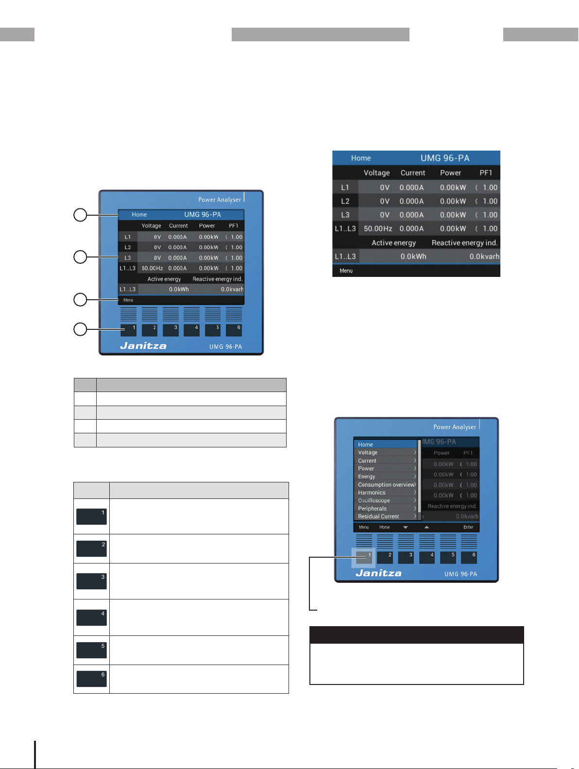
7.1 Operation
Your basic device with module 96-PA-RCM or
96-PA-RCM-EL can be operated via 6 function
buttons for:
· Selecting measuring displays.
· Navigation within the menus.
· Editing device settings.
4
3
2
1
Fig. Basic device - measuring display
Item Description
1 Function buttons
2 Function button labels
3 Measured value display
4 Title displayed
7.3 Measuring display
After restoration of network power, the UMG 96PA with module starts with the measured value
display Home.
Fig. Measured value display Home
In the as-delivered condition of the basic device
with module, the title of the measured value
display Home consists of the device type and the
serial number.
7.4 Menu
Pressing button 1 opens the Menu containing
the selection of all parameters and measured
variables to be set (menu items).
28
7.2 Button function
Button Function
· Display Menu
· Exit Menu
· Cancel action (ESC)
· Switch to Home display
· Select position (to the left “”)
· Select menu item or position
(down “”)
· Change (selection, number -1)
· Select menu item or position
(up “”)
· Change (selection, number +1)
· Select position (to the right “”)
· Confirm selection (Enter)
Fig. Measured value display Home with scroll
menu
Button 1 Menu
NOTE
You can find detailed information on operation,
measuring displays and button functions in the
installation instructions or in the user manual of
your basic device.
Page 29

www.janitza.de
7.5 Overview of the additional menu items for basic devices with module
Module 96-PA-RCM / 96-PA-RCM-EL
Menu items for the measuring modes Residual current
Menu
Home
Voltage
Current
Power
Energy
Consumption overview
Harmonics
Oscilloscope
Peripherals
Residual current
Overview
Bar chart
History, res. current 1
History, res. current 2
Configuration
Language
Communication
Field bus
Ethernet config. (-EL module only)
Measurement
Menu items for the measuring modes DC_power
Menu
Home
Voltage
Current
Power
Energy
Consumption overview
Harmonics
Oscilloscope
Peripherals
DC power
Overview
Bar chart
Configuration
Language
Communication
Field bus
Ethernet config. (-EL module only)
Measurement
Transformer
Nominal current
Nominal frequency
Module mode
Residual current
Temp. sensor
Display
System
Modbus editor
Current transformer
Voltage transformer
L4 current transf.
Residual current
DC power
Analog CH 1 type
Analog CH 2 type
Transformer
Cable break detect.
Transformer
Current transformer
Voltage transformer
L4 current transf.
Nominal current
Nominal frequency
Module mode
Residual current
DC power
DC power
Analog CH 1 type
Analog CH 2 type
Transformer
Cable break detect.
Temp. sensor
Display
System
Modbus editor
29
Page 30
Module 96-PA-RCM / 96-PA-RCM-EL
8. Communication
www.janitza.de
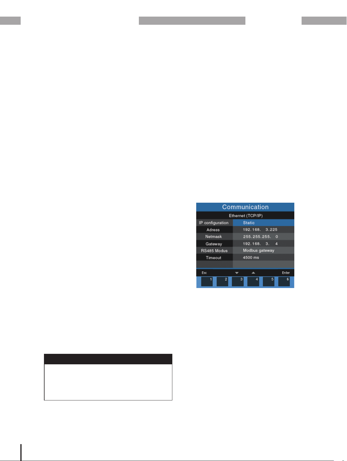
8.1 Basic device communication via the
Ethernet interface (module 96-PA-RCMEL)
The basic device with module 96-PA-RCM-EL
has six ways to allocate addresses for an Ethernet
connection (TCP/IP):
1. Static
The user selects the IP address, netmask and
gateway on the device. Use this mode for
simple networks with no DHCP server.
2. BOOTP
Automatically integrates your device in an
existing network. BOOTP is an older protocol
and has a smaller range of functions than
DHCP.
3. DHCP
On start-up, the device is automatically given
an IP address, netmask and gateway from the
DHCP server.
4. Static gratuitous ARP
The user selects the IP address, netmask
and gateway on the device. The device
automatically logs into the network with IP and
MAC address.
Configure the Ethernet settings or obtain details
from the window Communication > Ethernet
(TCP/IP):
· Press button 1 in the Home window to open
the Menu.
· With button 3 or 4, select the menu item
Configuration and confirm with key 6.
· In the Configuration window, use button 3 or 4 to
select the item Communication and confirm with
key 6.
· In the Communication window, use button 3 or
4 to select the item Ethernet Config and confirm
with button 6.
· The window Communication appears with the
Ethernet settings:
Configure your Ethernet (TCP/IP) settings as
described in chap. „7. Operation and button
functions of the basic device with module “ on
page 28.
5. BOOTP ARP Probe
Simplified protocol for the automatic
assignment of IP addresses to the MAC
addresses. The device automatically logs into
the network with IP and MAC address.
6. DHCP ARP Probe
Protocol for the automatic assignment of IP
addresses to the MAC addresses. The device
automatically logs into the network with IP and
MAC address.
NOTE
· The standard factory setting of the basic
device with module 96-PA-RCM-EL is
“dynamic assignment of IP address” (DHCP
mode).
· Consult your network administrator for the
Ethernet settings for your device.
Fig. Window Communication > Ethernet configuration
30
Page 31

www.janitza.de
Module 96-PA-RCM / 96-PA-RCM-EL
8.2 Basic device communication via the RS485 interface (field bus)
Communication via the RS-485 interface (field
bus) operates identically for basic devices with
and without module and can be accessed on the
user interface as follows:
1. Basic device with module 96-PA-RCM:
Display Home > button Menu > menu item
Configuration > item Communication
2. Basic device with module 96-PA-RCM-EL:
Display Home > button Menu > menu item
Configuration > item Communication > item
Field bus
8.3 Restarting the basic device
Some configurations might require a restart of
your basic device. To do so, proceed as follows:
1. In the Home display, press button 1, Menu.
2. In the scroll menu which appears, use buttons
“”/“”) to select the Configuration menu
3/4 (
item.
3. Press button 6 Enter.
4. The Configuration window appears.
5. In the Configuration window, use buttons
3/4 (“”/“”) to select the item System and
confirm with button 6 Enter.
6. The System window appears.
7. In the System window, use buttons 3/4
(“”/“”) to select the item Reset and confirm
with button 6 Enter.
8. The Reset window appears.
9. In the Reset window, use buttons 3/4
(“”/“”) to select the item Restart and
confirm with button 6 Enter.
10. The option No blinks.
11. Use button 4 to select the option Ye s and
confirm using button 6 Enter.
12. The basic device will restart.
Fig. Window Communication > Field bus configuration
NOTE
A detailed description of the Basic device
communication via the RS-485 interface (field
bus) can be found in the user manual of your
basic device.
Fig. Configuration menu item
Fig. Window Resetting with the Restart menu item
31
Page 32

Module 96-PA-RCM / 96-PA-RCM-EL
www.janitza.de
8.4 Module-relevant alarms
Fig. Example “Basic device warning alert when
communication to module is faulty”.
When there is an alarm, the following warning
alert appears:
When there is an alarm, the title bar of your device
display is shown in red with the time indicated. It
is also possible to activate blinking of the display
when there is an alarm using the Modbus editor or
the GridVis
®
software (see table below).
ATTENTION
A disconnected or defective module disrupts
the communication with the basic device and
leads to a device fault.
If communication between the basic device to
the module is lacking or faulty during operation,
a warning signal will appear on the display of the
basic device.
· Disconnect your system (the basic device)
from the power supply prior to mounting the
module.
· Check the positioning of the RCM module. If
necessary, apply slight pressure to press the
module onto the basic device until it audibly
snaps in.
· Check the display of your basic device (if the
menu item Residual currentis present, the
basic device has recognized the module).
· Prior to remounting, it may be necessary
to restart the basic device (chap. “8.3
Restarting the basic device” on page 31).
· If the measures indicated here are
unsuccessful, please contact our support
team (www.janitza.de).
· If there is discernible damage, send the
device, component or module back to the
manufacturer in compliance with proper
transport conditions.
Pressing function button 5 displays a list of all
alarms that have occurred, regardless of from
which menu window it is pressed. In the alarm list,
alarms can be selected and deleted.
Improper handling may cause damage to the
module and result in material damage!
The contacts of the module connector can bend
or break, which would destroy the module.
Once all alarms have been deleted, the device
closes the alarm list and goes to the last menu
window.
· Never touch or manipulate the contacts
of the module connector!
· Never use force to press the module
connector plug into the socket!
· When handling, transporting and storing the
module, protect the contacts of the module
Module-relevant alarm list:
Alarm description Display property
Warning limit value for RCM channel 1 exceeded
Alarm limit value for RCM channel 1 exceeded Display blinks
Warning limit value for RCM channel 2 exceeded
Alarm limit value for RCM channel 2 exceeded Display blinks
Overcurrent L4
Cable break on RCM channel 1
Cable break on RCM channel 2
No module communication for the last 10 seconds Display blinks
Tab. Alarm list with module-relevant alarms
connector!
NOTE
· More information on alarms and warning
alerts can be found in the user manual of
your basic device.
· A Modbus address list can be found in the
download area at www.janitza.de.
ATTENTION
32
Page 33

www.janitza.de
9. Module-relevant configurations
Module 96-PA-RCM / 96-PA-RCM-EL
Configure the relevant parameters for the module
in the Measurement window of your basic device
with module. To do so, use the function buttons
of the basic device to go to the Measurement
window:
· Open the Menu by pressing button 1 in the
Home window.
· Use buttons 3/4 (“”/“”) to select the menu
item Configuration and confirm with button 6
Enter.
· In the Configuration window, use buttons 3/4
(“”/“”) to select the item Measurement and
confirm with button 6 Enter.
· The Measurement window appears with the
following settings for the RCM module:
A. Transformer for the basic device (I1 to I3)
and L4 current transformer (I4 - neutral
conductor measurement).
B. Transformer for the module mode
Residual current or DC power.
C. Temperature sensor.
A
9.1 L4 current transformer
(I4 - measurement)
The Transformer item allows configuration of
the current and voltage transformer ratios of the
basic device as well as the current transformer
ratios for the L4 current measurement (e.g. neutral
conductor measurement).
1. Use buttons 3/4 (
Transformer and confirm with button 6 Enter.
2. The Window for configuration of the L4 (I4)
current transformer appears.
3. Select the item L4 (I4) current transformer and
confirm with button 6 Enter.
4. Use the function buttons of the basic device
to configure the current transformer ratio as
described in chap. „6.2 Activate cable break
detection (failure monitoring) RCM for I5 and
I6“ on page 20.
“”/“”) to select the item
A
B
C
Fig. Window Measurement with the L4 current transformer
for the RCM module (default setting 5 / 5 A).
Fig. Window Measurement with the settings for the
RCM module
33
Page 34

Module 96-PA-RCM / 96-PA-RCM-EL
B
9.2 Module mode
The Module mode item in the Measurement
window is for switching the measurement modes
1. Residual current or
2. DC power.
1. Module mode Residual current
· Use buttons 3/4 (
Module mode and confirm with button 6 Enter.
· The measuring mode set is displayed in yellow
(default setting Residual current).
· If necessary, use buttons 3/4 (“”/“”) to select
the item Residual current and confirm with
button 6 Enter.
· Afterwards, in the Measurement window, select
the item Residual current and confirm with
button 6, Enter.
· The window Display “Residual current” appears
with the parameters to be set:
“”/“”) to select the item
www.janitza.de
Residual current
No.
parameters
Analog CH 1
1
type,
I5 terminal 29/30
Analog CH 2
2
type,
I6 terminal 31/32
Transformer
3
ratios
Cable break
4
detection
Tab. Settings options in the residual current module mode
2. Module mode DC power
· Use buttons 3/4 (“”/“”) to select the item
Module mode and confirm with button 6 Enter.
· The measuring mode set is displayed in yellow.
· Use buttons 3/4 (“”/“”) to select the item DC
power and confirm with button 6 Enter.
· Afterwards, in the Measurement window, select
the item DC power.
Settings
Suitable transformer types:
· AC (0 .. 30 A
· 0 .. 20 mA
· 4 .. 20 mA
Suitable transformer types:
· AC (0 .. 30 A
· 0 .. 20 mA
· 4 .. 20 mA
Current transformer:
· CH 1 - prim. and sec.
· CH 2 - prim. and sec.
Configurable in the GridVis
software and in the Modbus
editor (basic device).
rms
rms
)
)
®
34
Fig. Window Measurement > Module mode “Residual current”
1
2
3
4
Fig. Window Display “Residual current” with the
settings of the parameters for the measuring modes
Residual current.
Fig. Window Measurement > Module mode “DC power”
· To go to the Display window with the parameters
for the DC power measurement modes to be set,
press button 6 Enter.
Page 35

www.janitza.de
1
2
3
4
Module 96-PA-RCM / 96-PA-RCM-EL
DC power measurement:
Transformer ratio for the input I6/U6
20 mA
10 mA
Fig. Window Display with the DC power parameters
DC power
No.
1
2
3
4
parameters
Analog CH 1
type,
I5 terminal 29/30
Analog CH 2
type,
1)
I6/U6
terminal 31/32
Transformer
2)
ratios
Cable break
detection
Settings
Suitable transformer types:
· 0 .. 20 mA
· 4 .. 20 mA
Suitable transformer types:
· 0 .. 20 mA
· 4 .. 20 mA
Current transformer:
· CH 1 - prim. and sec.
· CH 2 - prim. and sec.
Configurable in the GridVis
software and in the Modbus
editor (basic device).
1) Power is determined from inputs I5 and I6 (U6)
during the DC power measurement. A voltage
(U6) is converted into a current signal by an
active current transformer. The current signal
responds proportionately to the value of the
input voltage.
2) To set the transformer type 0..20 mA for CH2,
configure a primary voltage and a proportional
secondary current for the transformer ratio.
Current signal (secondary)
0 mA
0 V
350 V
700 V
Voltage (primary)
Fig. Graph “Transformer” analog input I6/U6
C
9.3 Temperature sensor
1. In the Measurement window, select the item
Temperature sensor and press button 6 Enter.
®
2. The temperature sensor item blinks.
3. Use buttons 3/4 (
“”/“”) to select your
temperature sensor from the list:
- PT100 (default setting)
- PT1000
- KTY83
- KTY84
4. Confirm using button 6 Enter.
Fig. Window Measurement with the configuration
of the transformer for the DC power measuring modes.
Fig. Window Measurement > Configuration of the temperature
sensor
NOTE
You can also configure the temperature sensor
of your basic device conveniently via the PC
connection to the GridVis® software (in scope of
delivery).
35
Page 36

Module 96-PA-RCM / 96-PA-RCM-EL
9.4 Module-relevant configurations in the
GridVis
® software
www.janitza.de
All module-relevant settings can also be easily
®
configured in the GridVis
network visualization
software.
Fig. User interface of the GridVis® network visualization software
9.5 Modbus editor
The basic device with module has a Modbus
editor in the user interface. The Modbus editor
item in the Configuration window provides access
(read/write) to the Modbus addresses (Menu >
Configuration > Modbus editor).
Fig. Window Configuration with the Modbus
editor menu item
Fig. Configuration of the Modbus editor
NOTE
There is a Modbus address list available for
download at www.janitza.de.
Recommendation:
We recommend use of the GridVis® network
visualization software for convenient and fast
configuration of all module-relevant settings.
36
Page 37

www.janitza.de
Module 96-PA-RCM / 96-PA-RCM-EL
37
Page 38

Module 96-PA-RCM / 96-PA-RCM-EL
10. Module-relevant measuring displays
10.1 Measuring display L4 current measurement
www.janitza.de
Current menu
History selection for L4
10.2 Measuring display Residual current
Residual current menu
History of I-L4
Overview Bar chart
Measuring display for Current, Current
(max.), Limit value and Reference value of
RCM1 and RCM2.
History, res. current 1
History of I-RCM1 History of I-RCM2
Bar chart of the I-RCM1 and I-RCM2
measured values.
History, res. current 2
38
Page 39

www.janitza.de
10.3 Measuring display DC power
DC power menu
Module 96-PA-RCM / 96-PA-RCM-EL
Overview Bar chart
Measuring display for Voltage, Current,
Power and Energy (plus min and max.
values).
10.4 Measuring display External temperature
Peripherals menu
Selection of Ext. temp.
Bar chart of the voltage, current and
power measured values.
Ext. temp.
Bar chart and measuring display for the
temperature (with min. and max. values)
39
Page 40

Module 96-PA-RCM / 96-PA-RCM-EL
11. Technical data for the module
11.1 Technical data
General
Net weight of module
(with attached plug-in connectors)
Impact resistance IK07 according to IEC 62262
Transport and storage
The following specifications apply for devices transported and stored in the original packaging.
Free fall 1 m (39.37 in)
Temperature K55
Relative air humidity (non-condensing) 0 to 90% RH
Environmental conditions during operation, see the usage information for your basic device.
Analog inputs
Differential or current signals 2x
Temperature measurement 1x
www.janitza.de
78 g (0.17 lbs)
-25° C (-13 °F) to +70° C (158 °F)
Residual current input
Nominal current 30 mA
Measurement range 0 .. 30 mA
Operating current 50 µA
Resolution
Cable break detection (failure monitoring) Can be activated
Crest factor 1.414 (relative to 30 mA)
Load 4 Ω
Overload for 1 s 1 A
Constant overloaded 200 mA
Measurement of residual currents
Temperature measurement
Update time 200 ms
Suitable thermal sensor PT100, PT1000, KTY83, KTY84
Total burden (thermal sensor and lead) max. 4 kΩ
Thermal sensor
type
PT100 -99 °C (-146.2 °F) ... +500 °C (932 °F) 60 Ω ... 180 Ω ±1,5% rng
PT1000 -99 °C (-146.2 °F) ... +500 °C (932 °F) 600 Ω ... 1,8 kΩ ±1,5% rng
KTY83 -55 °C (-67 °F) ... +175 °C (347 °F) 500 Ω ... 2,6 kΩ ±1,5% rng
KTY84 -40 °C (-40 °F) ... +300 °C (572 °F) 350 Ω ... 2,6 kΩ ±1,5% rng
Temperature range Resistance range
1 µA
According to IEC/TR 60755 (2008-01):
Type A
Type B and B+
| 0...20 mA | 4...20 mA
rms
rms
Measurement
uncertainty
40
Page 41

www.janitza.de
Module 96-PA-RCM / 96-PA-RCM-EL
Current measurement I4
Nominal current 5 A
Measurement range 0.005 .. 6 A
Crest factor 2 (relative to 6 A
rms
rms
)
Overvoltage category 300 V CAT II
Power consumption approx. 0.2 VA (Ri = 5 mΩ)
Sampling frequency 8,33 kHz
Resolution 16 bit
Rated surge voltage 2.5 kV
Overload for 1 s 60 A (sinusoidal)
Ethernet interface (only module 96-PA-RCM-EL)
Connection RJ45
Functions Modbus gateway
Protocols ARP, IPv4, ICMP (ping)
TCP, UDP Port: Application specific
Modbus TCP Port: 502
Modbus UDP Port: 502
DHCP/BootP Port: 67/68 (UDP)
DNS server Port: 53 (UDP)
NTP server Port: 123 (UDP)
Terminal connection capacity – Analog inputs (residual current, current signals, temperature)
Connectible conductors Connect one conductor per terminal position!
2
Single core, multi-core, fine-stranded 0.2 - 1.5 mm
Wire ferrules (non-insulated) 0.2 - 1.5 mm
Wire ferrules (insulated) 0.2 - 1.5 mm
, AWG 28-16
2
, AWG 26-16
2
, AWG 26-16
Tightening torque 0.2 - 0.25 Nm (1.77 - 2.21 lbf in)
Strip length 7 mm (0.2756 in)
Terminal connection capacity (current measurement I4)
Connectible conductors Connect one conductor per terminal position!
2
Single core, multi-core, fine-stranded 0.2 - 4 mm
Wire ferrules (non-insulated) 0.2 - 4 mm
Wire ferrules (insulated) 0.2 - 2.5 mm
, AWG 28-12
2
, AWG 26-12
2
, AWG 26-14
Tightening torque 0.4 - 0.5 Nm (3.54 - 4.43 lbf in)
Strip length 7 mm (0.2756 in)
Cable lengths for analog input, residual current input, temperature measurement input, current measurement
input I4
Up to 30 m (32.81 yd) Unshielded
Greater than 30 m (32.81 yd) Shielded
Potential isolation and electrical safety of the temperature measurement input
The temperature measurement input has:
· Double insulation relative to the current measurement inputs, voltage measurement inputs and the supply voltage.
· No insulation relative to the residual current input (RCM).
· A functional isolation relative to the Ethernet interface.
The external temperature sensor must have double insulation relative to hazardous contact voltage (according to
IEC 61010-1:2010).
41
Page 42

Module 96-PA-RCM / 96-PA-RCM-EL
11.2 Performance characteristics of functions
Function Symbol Accuracy class Measurement range Display range
Neutral conductor
current I4, measured
Neutral conductor
current I4, calculated
Residual currents I5, I6 I
Temperature T -
Table of module-relevant “Performance characteristics of functions”.
I
N
I
Nc
Diff
www.janitza.de
1 (IEC61557-12) 0 .. 6 A
rms
1.0 (IEC61557-12) 0.03 .. 25 A 0.03 A .. 999 kA
1 (IEC61557-12) 0 .. 30 mA
rms
See
temperature sensor
types
0 A .. 999 kA
0 A .. 999 kA
0 °C ... +100 °C
(32 °F ... 212 °F)
42
Page 43

www.janitza.de
Module 96-PA-RCM / 96-PA-RCM-EL
43
Page 44

Module 96-PA-RCM / 96-PA-RCM-EL
12. Dimensional drawings and views
12.1 Dimensional drawings
· All specifications in mm (in).
· The figures show the module 96-PA-RCM-EL and serve the purpose of illustration.
· The views shown are not true to scale.
www.janitza.de
Rear view (with connections)
90.7 mm (3.57 in)
30.8 mm (1.21 in)
32.2 mm (1.27 in)
17.2 mm
(0.68 in)
Side view
45.8 mm (1.8 in)
58.5 mm (2.3 in)
Top view 3D view
44
12.2 3D views of basic device with module
Page 45

www.janitza.de
13. Dismounting
Module 96-PA-RCM / 96-PA-RCM-EL
Dismounting module 96-PA-RCM or 96PA-RCM-EL:
1. Disconnect the system (basic device) from the
power supply!
2. Unsnap your module by carefully lifting the
snapping mechanism (using your fingernail or
a screwdriver, if necessary) and pull it out of
the slot.
ATTENTION
Handling your module too roughly may cause
damage to the module and result in material
damage!
When snapping in the module, the snapping
mechanism can be damaged or broken off.
· Lift the snapping mechanism with care
and using only slight pressure! Preferably
use your fingernail (or a screwdriver, if
necessary) to do so.
ATTENTION
Dismounting or disconnecting the module
while it is communicating with the basic device
will result in a device fault!
If communication between the basic device
to the module is lacking or faulty during
operation, a warning signal will appear on
the display of the basic device (see chap. “8.4
Module-relevant alarms” on page 32
· Disconnect your system (the basic device)
from the power supply prior to dismounting or
disconnecting the module!
· Prior to remounting, it may be necessary to
restart the basic device (chap. “8.3 Restarting
the basic device” on page 31).
Snapping mechanism
Groove
Fig. Rear view of basic device with module, snapping mechanism
and groove
Groove
45
Page 46

Module 96-PA-RCM / 96-PA-RCM-EL
14. Service and maintenance
www.janitza.de
Prior to outbound delivery, your device
(component/module) is subjected to various
safety tests and is marked with a seal. If the
device (component/module) is opened, the safety
tests must be repeated. The warranty is only valid
for unopened devices (components/modules).
14.1 Repairs and calibration
Repairs and calibration can only be carried out by
the manufacturer.
14.2 Service
If questions arise which are not described in this
user manual, please contact the manufacturer.
To answer your questions, it is essential that you
provide the following information:
· Device designation (see rating plate).
· Serial number (see rating plate).
· Hardware version (see system display).
· Software release (see system display).
· Measured voltage and supply voltage.
· An exact error description.
14.3 Device adjustment
Devices (components/modules) are adjusted by
the manufacturer prior to outbound delivery. No
readjustment is required when the environmental
conditions are complied with.
14.4 Calibration interval
A recalibration by the manufacturer or an
accredited laboratory is recommended after about
5 years.
14.5 Firmware update
To carry out a firmware update, connect the basic
device with module to your computer with the
GridVis
· Open the Firmware Update Assistant in the
· Select a corresponding update file and carry out
®
software installed:
GridVis® software by clicking “Update device” in
the “Extras” menu.
the update.
NOTE
This user manual describes the module and
provides information on the operation of the
module via the basic device.
In addition to this user manual, also take note of
the documentation of your basic device, such as:
· User manual
· Installation instructions
· “GridVis® Software” Quick Guide
· Safety information
Moreover, the GridVis® software has an “online
help” feature.
14.6 Procedure in the event of a malfunction
ATTENTION
An error in the communication with the basic
device leads to a device fault!
If communication between the basic device to
the module is lacking or faulty during operation,
a warning signal will appear on the display of the
basic device.
· Disconnect the basic device (system) from
the power supply prior to dismounting or
disconnecting the module!
· Prior to remounting, it may be necessary
to restart the basic device (see chap. “8.3
Restarting the basic device” on page 31).
· Also take note of the chapter “Procedure
in the event of a malfunction” in the
documentation of your basic device.
· If the measures indicated here are
unsuccessful, please contact our support
team (www.janitza.de).
· If there is discernible damage, send the
device, component or module back to the
manufacturer in compliance with proper
transport conditions.
14.7 Resetting the module to the standard
factory settings
“Reset to standard factory settings” can be
carried out for the module via your basic device.
A description of this can be found in the user
manual of your basic device.
46
Page 47

www.janitza.de
Module 96-PA-RCM / 96-PA-RCM-EL
47
Page 48

Janitza electronics GmbH
Vor dem Polstück 6
D-35633 Lahnau
Tel.: +49 6441 - 9642-0
Fax: +49 6441 - 9642-30
Email: info@janitza.de
info@janitza.de | www.janitza.de
The current version of the document can be found in the download area at www.janitza.de.
Doc. no. 2.061.033.0 | Date 09/2019 | Subject to technical changes.
 Loading...