

Page 1
1 / 10
Allgemeines
1
2
Janitza electronics GmbH
Vor dem Polstück 6
D-35633 Lahnau
Support Tel. +49 6441 9642-22
Fax +49 6441 9642-30
E-Mail: info@janitza.de
www.janitza.de
www.janitza.de
Dok.-Nr. 2.061.025.0b 12/2018 Art.-Nr. 33.03.374
English version:
see rear side
2
Sicherheit
Sicherheitshinweise
Die Installationsanleitung stellt kein vollständiges
Verzeichnis aller für den Betrieb des Geräts erfor-
derlichen Sicherheitsmaßnahmen dar.
Besondere Betriebsbedingungen können weitere
Maßnahmen erfordern. Die Installationsanleitung
enthält Hinweise, die Sie zu Ihrer persönlichen
Sicherheit und zur Vermeidung von Sachschäden
beachten müssen.
Verwendete Symbole auf dem Gerät:
Haftungsausschluss
Die Beachtung der Informationsprodukte zu
den Geräten ist Voraussetzung für den sicheren
Betrieb und um angegebene Leistungsmerkma-
le und Produkteigenschaften zu erreichen. Für
Personen-, Sach - oder Vermögensschäden, die
durch Nichtachtung der Informationsprodukte
entstehen, übernimmt die Janitza electronics
GmbH keine Haftung. Sorgen Sie dafür, dass Ihre
Informationsprodukte leserlich zugänglich sind.
Weiterführende Dokumentationen, wie z. B.
Benutzerhandbücher zu den Basisgeräten und
Modulen, fi nden Sie auf unserer Website
www.janitza.de unter Support > Downloads.
Urheberrechtsvermerk
© 2018 - Janitza electronics GmbH - Lahnau.
Alle Rechte vorbehalten. Jede, auch auszugswei-
se, Vervielfältigung, Bearbeitung, Verbreitung und
sonstige Verwertung ist verboten.
Technische Änderungen vorbehalten
• Achten Sie darauf, dass Ihr Gerät mit der
Installationsanleitung übereinstimmt.
• Lesen und verstehen Sie zunächst produktbe-
gleitende Dokumente.
• Produktbegleitende Dokumente während der
gesamten Lebensdauer verfügbar halten und
gegebenenfalls an nachfolgende Benutzer
weitergeben.
• Bitte informieren Sie sich über Geräte-Revisio-
nen und die damit verbundenen Anpassungen
der produktbegleitenden Dokumentation auf
www.janitza.de.
Entsorgung
Bitte beachten Sie nationale Bestimmungen! Ent-
sorgen Sie gegebenenfalls einzelne Teile, je nach
Beschaffenheit und existierende länderspezifi sche
Vorschriften, z.B. als:
• Elektroschrott
• Kunststoffe
• Metalle
oder beauftragen Sie einen zertifi zierten
Entsorgungsbetrieb mit der Verschrottung.
Relevante Gesetze,
angewendete Normen und Richtlinien
Die von der Janitza electronics GmbH angewen-
deten Gesetze, Normen und Richtlinien für das
Gerät entnehmen Sie der Konformitätserklärung
auf unserer Website (www.janitza.de).
Benutzerhandbuch:
RCM-Module
Erweiterungsmodule für das UMG 96-PA
Installationsanleitung
Modul 96-PA-RCM
Modul 96-PA-RCM-EL
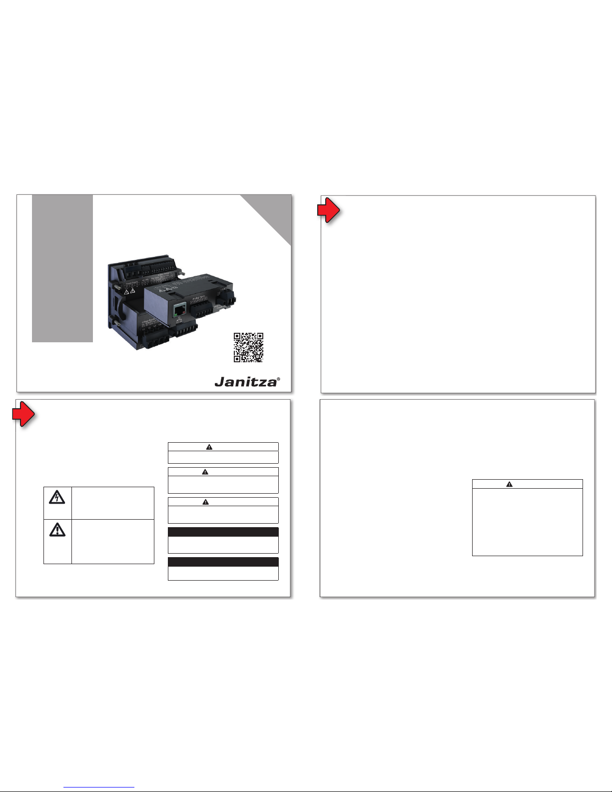
Abb.
UMG 96-PA mit Modul 96-PA-RCM-EL (mit Ethernet-Schnittstelle)
Allgemeines
1
2
2
Sicherheit
Sicherheitshinweise
Die Installationsanleitung stellt kein vollständiges
Verzeichnis aller für den Betrieb des Geräts erfor-
derlichen Sicherheitsmaßnahmen dar.
Besondere Betriebsbedingungen können weitere
Maßnahmen erfordern. Die Installationsanleitung
enthält Hinweise, die Sie zu Ihrer persönlichen
Sicherheit und zur Vermeidung von Sachschäden
beachten müssen.
Verwendete Symbole auf dem Gerät:
Das zusätzliche Symbol auf dem
Gerät selbst deutet auf eine elekt-
rische Gefahr hin, die zu schweren
Verletzungen oder Tod führen
kann.
Das allgemeine Warnsymbol
macht Sie auf mögliche Verlet-
zungsgefahren aufmerksam.
Beachten Sie alle unter diesem
Symbol aufgeführten Hinweise, um
mögliche Verletzungen oder gar
Todesfälle zu vermeiden.
Sicherheitshinweise in der Installationsanleitung
sind durch ein Warndreieck hervorgehoben und je
nach Gefährdungsgrad wie folgt dargestellt:
Maßnahmen zur Sicherheit
Beim Betrieb elektrischer Geräte stehen zwangs-
läufi g bestimmte Teile dieser Geräte unter gefähr-
licher Spannung. Es können deshalb schwere
Körperverletzung oder Sachschäden auftreten,
wenn nicht fachgerecht gehandelt wird:
Haftungsausschluss
Die Beachtung der Informationsprodukte zu
den Geräten ist Voraussetzung für den sicheren
Betrieb und um angegebene Leistungsmerkmale und Produkteigenschaften zu erreichen. Für
Personen-, Sach - oder Vermögensschäden, die
durch Nichtachtung der Informationsprodukte
entstehen, übernimmt die Janitza electronics
GmbH keine Haftung. Sorgen Sie dafür, dass Ihre
Informationsprodukte leserlich zugänglich sind.
Weiterführende Dokumentationen, wie z. B.
Benutzerhandbücher zu den Basisgeräten und
Modulen, fi nden Sie auf unserer Website
www.janitza.de unter Support > Downloads.
Urheberrechtsvermerk
© 2018 - Janitza electronics GmbH - Lahnau.
Alle Rechte vorbehalten. Jede, auch auszugsweise, Vervielfältigung, Bearbeitung, Verbreitung und
sonstige Verwertung ist verboten.
Technische Änderungen vorbehalten
• Achten Sie darauf, dass Ihr Gerät mit der
Installationsanleitung übereinstimmt.
• Lesen und verstehen Sie zunächst produktbegleitende Dokumente.
• Produktbegleitende Dokumente während der
gesamten Lebensdauer verfügbar halten und
gegebenenfalls an nachfolgende Benutzer
weitergeben.
• Bitte informieren Sie sich über Geräte-Revisionen und die damit verbundenen Anpassungen
der produktbegleitenden Dokumentation auf
www.janitza.de.
Entsorgung
Bitte beachten Sie nationale Bestimmungen! Entsorgen Sie gegebenenfalls einzelne Teile, je nach
Beschaffenheit und existierende länderspezifi sche
Vorschriften, z.B. als:
• Elektroschrott
• Kunststoffe
• Metalle
oder beauftragen Sie einen zertifi zierten
Entsorgungsbetrieb mit der Verschrottung.
Relevante Gesetze,
angewendete Normen und Richtlinien
Die von der Janitza electronics GmbH angewendeten Gesetze, Normen und Richtlinien für das
Gerät entnehmen Sie der Konformitätserklärung
auf unserer Website (www.janitza.de).
HINWEIS
Verweist auf Vorgänge bei denen die Gefahr von
Verletzungen oder Sachschäden nicht besteht.
ACHTUNG
Weist auf eine unmittelbar gefährliche Situation
hin, die bei Nichtbeachtung zu Sachschäden oder
Umweltschäden führen kann.
VORSICHT
Weist auf eine möglicherweise gefährliche
Situation hin, die zu leichten Verletzungen oder
Sachschäden führen kann.
WARNUNG
Weist auf eine möglicherweise gefährliche Situa-
tion hin, die zu schweren Verletzungen oder Tod
führen kann.
GEFAHR
Weist auf eine unmittelbar drohende Gefahr hin,
die zu schweren bzw. tödlichen Verletzungen führt.
2
2
Sicherheit
Sicherheitshinweise
Die Installationsanleitung stellt kein vollständiges
Verzeichnis aller für den Betrieb des Geräts erforderlichen Sicherheitsmaßnahmen dar.
Besondere Betriebsbedingungen können weitere
Maßnahmen erfordern. Die Installationsanleitung
enthält Hinweise, die Sie zu Ihrer persönlichen
Sicherheit und zur Vermeidung von Sachschäden
beachten müssen.
Verwendete Symbole auf dem Gerät:
Das zusätzliche Symbol auf dem
Gerät selbst deutet auf eine elektrische Gefahr hin, die zu schweren
Verletzungen oder Tod führen
kann.
Das allgemeine Warnsymbol
macht Sie auf mögliche Verletzungsgefahren aufmerksam.
Beachten Sie alle unter diesem
Symbol aufgeführten Hinweise, um
mögliche Verletzungen oder gar
Todesfälle zu vermeiden.
Sicherheitshinweise in der Installationsanleitung
sind durch ein Warndreieck hervorgehoben und je
nach Gefährdungsgrad wie folgt dargestellt:
Maßnahmen zur Sicherheit
Beim Betrieb elektrischer Geräte stehen zwangs-
läufi g bestimmte Teile dieser Geräte unter gefähr-
licher Spannung. Es können deshalb schwere
Körperverletzung oder Sachschäden auftreten,
wenn nicht fachgerecht gehandelt wird:
• Vor Anschluss von Verbindungen das Gerät,
am Schutzleiteranschluss, wenn vorhanden,
erden.
• Gefährliche Spannungen können in allen
mit der Spannungsversorgung verbundenen
Schaltungsteilen anstehen.
• Auch nach Abtrennen der Versorgungsspan-
nung können gefährliche Spannungen im
Gerät vorhanden sein (Kondensatorspeicher).
• Betriebsmittel mit Stromwandlerkreisen nicht
offen betreiben.
• Die im Benutzerhandbuch und auf dem Typen-
schild genannten Grenzwerte nicht überschrei-
ten! Dies ist auch bei der Prüfung und der
Inbetriebnahme zu beachten!
• Beachten Sie Sicherheits- und Warnhinwei-
se in den Dokumenten, die zu den Geräten
gehören!
Bestimmungsgemäße Verwendung
Die Module 96-PA-RCM und 96-PA-RCM-EL
• sind als Aufsteckmodule für das Basisgerät
• dürfen nur auf spannungsfrei geschaltete
• sind nicht für den Einbau in Fahrzeuge
• sind nicht für den Einbau in Umgebungen mit
WARNUNG
Verletzungsgefahr durch elektrische Spannung!
Schwere Körperverletzungen oder Tod können
erfolgen durch:
· Berühren von blanken oder abisolierten Adern,
die unter Spannung stehen.
· Berührungsgefährliche Eingänge des Geräts.
Vor Arbeitsbeginn an Ihrer Anlage:
· Die Anlage spannungsfrei schalten!
· Gegen Wiedereinschalten sichern!
· Spannungsfreiheit feststellen!
· Erden und Kurzschließen!
· Benachbarte, unter Spannung stehende
Teile abdecken oder abschranken!
HINWEIS
Verweist auf Vorgänge bei denen die Gefahr von
Verletzungen oder Sachschäden nicht besteht.
ACHTUNG
Weist auf eine unmittelbar gefährliche Situation
hin, die bei Nichtbeachtung zu Sachschäden oder
Umweltschäden führen kann.
VORSICHT
Weist auf eine möglicherweise gefährliche
Situation hin, die zu leichten Verletzungen oder
Sachschäden führen kann.
WARNUNG
Weist auf eine möglicherweise gefährliche Situation hin, die zu schweren Verletzungen oder Tod
führen kann.
GEFAHR
Weist auf eine unmittelbar drohende Gefahr hin,
die zu schweren bzw. tödlichen Verletzungen führt.
Eingangskontrolle
Der einwandfreie und sichere Betrieb der Geräte
und der RCM-Module setzen sachgemäßen
Transport, fachgerechte Lagerung, Aufstellung
und Montage sowie sorgfältige Bedienung und
Instandhaltung voraus.
Nehmen Sie das Aus- und Einpacken mit der üb-
lichen Sorgfalt ohne Gewaltanwendung und nur
unter Verwendung von geeignetem Werkzeug vor.
Qualifi ziertes Personal
Um Personen- und Sachschäden zu vermeiden,
darf nur qualifi ziertes Personal mit elektrotechni-
scher Ausbildung am Gerät arbeiten mit Kennt-
nissen
• der nationalen Unfallverhütungsvorschriften
• in Standards der Sicherheitstechnik
• in Installation, Inbetriebnahme und Betrieb des
Geräts.
Maßnahmen zur Sicherheit
Beim Betrieb elektrischer Geräte stehen zwangsläufi g bestimmte Teile dieser Geräte unter gefährlicher Spannung. Es können deshalb schwere
Körperverletzung oder Sachschäden auftreten,
wenn nicht fachgerecht gehandelt wird:
• Vor Anschluss von Verbindungen das Gerät,
am Schutzleiteranschluss, wenn vorhanden,
erden.
• Gefährliche Spannungen können in allen
mit der Spannungsversorgung verbundenen
Schaltungsteilen anstehen.
• Auch nach Abtrennen der Versorgungsspannung können gefährliche Spannungen im
Gerät vorhanden sein (Kondensatorspeicher).
• Betriebsmittel mit Stromwandlerkreisen nicht
offen betreiben.
• Die im Benutzerhandbuch und auf dem Typenschild genannten Grenzwerte nicht überschreiten! Dies ist auch bei der Prüfung und der
Inbetriebnahme zu beachten!
• Beachten Sie Sicherheits- und Warnhinwei-
se in den Dokumenten, die zu den Geräten
gehören!
Bestimmungsgemäße Verwendung
Die Module 96-PA-RCM und 96-PA-RCM-EL
• sind als Aufsteckmodule für das Basisgerät
UMG 96-PA in Schaltschränken und Installati-
onskleinverteilern bestimmt. Die Einbaulage ist
beliebig (Bitte beachten Sie die zum Basisge-
rät gehörende Dokumentation).
• dürfen nur auf spannungsfrei geschaltete
Basisgeräte montiert werden (siehe Schritt
„Montage“).
• sind nicht für den Einbau in Fahrzeuge
bestimmt! Der Einsatz des Basisgeräts mit
Modul in nicht ortsfesten Ausrüstungen gilt als
außergewöhnliche Umweltbedingung und ist
nur nach gesonderter Vereinbarung zulässig.
• sind nicht für den Einbau in Umgebungen mit
schädlichen Ölen, Säuren, Gasen, Dämpfen,
Stäuben, Strahlungen, usw. bestimmt.
WARNUNG
Verletzungsgefahr durch elektrische Spannung!
Schwere Körperverletzungen oder Tod können
erfolgen durch:
· Berühren von blanken oder abisolierten Adern,
die unter Spannung stehen.
· Berührungsgefährliche Eingänge des Geräts.
Vor Arbeitsbeginn an Ihrer Anlage:
· Die Anlage spannungsfrei schalten!
· Gegen Wiedereinschalten sichern!
· Spannungsfreiheit feststellen!
· Erden und Kurzschließen!
· Benachbarte, unter Spannung stehende
Teile abdecken oder abschranken!
Eingangskontrolle
Der einwandfreie und sichere Betrieb der Geräte
und der RCM-Module setzen sachgemäßen
Transport, fachgerechte Lagerung, Aufstellung
und Montage sowie sorgfältige Bedienung und
Instandhaltung voraus.
Nehmen Sie das Aus- und Einpacken mit der üb-
lichen Sorgfalt ohne Gewaltanwendung und nur
unter Verwendung von geeignetem Werkzeug vor.
Prüfen Sie:
• Geräte und Module durch Sichtkontrolle auf
einwandfreien mechanischen Zustand.
• den Lieferumfang (siehe Benutzerhandbuch)
auf Vollständigkeit bevor Sie mit der Montage
und Installation Ihrer Geräte beginnen.
Wenn anzunehmen ist, dass ein gefahrloser
Betrieb nicht mehr möglich ist, so setzen Sie Ihr
Basisgerät mit Modul unverzüglich außer Betrieb
und sichern es gegen unbeabsichtigte Inbetrieb-
nahme.
Es ist anzunehmen, dass ein gefahrloser Betrieb
unmöglich ist, wenn das Gerät mit Modul z.B.:
• sichtbare Beschädigungen aufweist,
• trotz intakter Netzversorgung nicht mehr
arbeitet,
• längere Zeit ungünstigen Verhältnissen (z.B.
Lagerung außerhalb der zulässigen Klimagren-
zen ohne Anpassung an das Raumklima, Be-
tauung o.Ä.) oder Transportbeanspruchungen
(z.B. Fall aus großer Höhe auch ohne sichtbare
äußere Beschädigung o.Ä..) ausgesetzt war.
Qualifi ziertes Personal
Um Personen- und Sachschäden zu vermeiden,
darf nur qualifi ziertes Personal mit elektrotechnischer Ausbildung am Gerät arbeiten mit Kenntnissen
• der nationalen Unfallverhütungsvorschriften
• in Standards der Sicherheitstechnik
• in Installation, Inbetriebnahme und Betrieb des
Geräts.
Page 2
2 / 10
Bestimmungsgemäße Verwendung
Die Module 96-PA-RCM und 96-PA-RCM-EL
• sind als Aufsteckmodule für das Basisgerät
UMG 96-PA in Schaltschränken und Installationskleinverteilern bestimmt. Die Einbaulage ist
beliebig (Bitte beachten Sie die zum Basisgerät gehörende Dokumentation).
• dürfen nur auf spannungsfrei geschaltete
Basisgeräte montiert werden (siehe Schritt
„Montage“).
• sind nicht für den Einbau in Fahrzeuge
bestimmt! Der Einsatz des Basisgeräts mit
Modul in nicht ortsfesten Ausrüstungen gilt als
außergewöhnliche Umweltbedingung und ist
nur nach gesonderter Vereinbarung zulässig.
• sind nicht für den Einbau in Umgebungen mit
schädlichen Ölen, Säuren, Gasen, Dämpfen,
Stäuben, Strahlungen, usw. bestimmt.
Eingangskontrolle
Der einwandfreie und sichere Betrieb der Geräte
und der RCM-Module setzen sachgemäßen
Transport, fachgerechte Lagerung, Aufstellung
und Montage sowie sorgfältige Bedienung und
Instandhaltung voraus.
Nehmen Sie das Aus- und Einpacken mit der üblichen Sorgfalt ohne Gewaltanwendung und nur
unter Verwendung von geeignetem Werkzeug vor.
Prüfen Sie:
• Geräte und Module durch Sichtkontrolle auf
einwandfreien mechanischen Zustand.
• den Lieferumfang (siehe Benutzerhandbuch)
auf Vollständigkeit bevor Sie mit der Montage
und Installation Ihrer Geräte beginnen.
Wenn anzunehmen ist, dass ein gefahrloser
Betrieb nicht mehr möglich ist, so setzen Sie Ihr
Basisgerät mit Modul unverzüglich außer Betrieb
und sichern es gegen unbeabsichtigte Inbetriebnahme.
Es ist anzunehmen, dass ein gefahrloser Betrieb
unmöglich ist, wenn das Gerät mit Modul z.B.:
• sichtbare Beschädigungen aufweist,
• trotz intakter Netzversorgung nicht mehr
arbeitet,
• längere Zeit ungünstigen Verhältnissen (z.B.
Lagerung außerhalb der zulässigen Klimagrenzen ohne Anpassung an das Raumklima, Betauung o.Ä.) oder Transportbeanspruchungen
(z.B. Fall aus großer Höhe auch ohne sichtbare
äußere Beschädigung o.Ä..) ausgesetzt war.
Allgemeines
1
2
Janitza electronics GmbH
Vor dem Polstück 6
D-35633 Lahnau
Support Tel. +49 6441 9642-22
Fax +49 6441 9642-30
E-Mail: info@janitza.de
www.janitza.de
www.janitza.de
Dok.-Nr. 2.061.025.0b 12/2018 Art.-Nr. 33.03.374
English version:
see rear side
2
Sicherheit
Sicherheitshinweise
Die Installationsanleitung stellt kein vollständiges
Verzeichnis aller für den Betrieb des Geräts erfor-
derlichen Sicherheitsmaßnahmen dar.
Besondere Betriebsbedingungen können weitere
Maßnahmen erfordern. Die Installationsanleitung
enthält Hinweise, die Sie zu Ihrer persönlichen
Sicherheit und zur Vermeidung von Sachschäden
beachten müssen.
Verwendete Symbole auf dem Gerät:
Haftungsausschluss
Die Beachtung der Informationsprodukte zu
den Geräten ist Voraussetzung für den sicheren
Betrieb und um angegebene Leistungsmerkma-
le und Produkteigenschaften zu erreichen. Für
Personen-, Sach - oder Vermögensschäden, die
durch Nichtachtung der Informationsprodukte
entstehen, übernimmt die Janitza electronics
GmbH keine Haftung. Sorgen Sie dafür, dass Ihre
Informationsprodukte leserlich zugänglich sind.
Weiterführende Dokumentationen, wie z. B.
Benutzerhandbücher zu den Basisgeräten und
Modulen, fi nden Sie auf unserer Website
www.janitza.de unter Support > Downloads.
Urheberrechtsvermerk
© 2018 - Janitza electronics GmbH - Lahnau.
Alle Rechte vorbehalten. Jede, auch auszugswei-
se, Vervielfältigung, Bearbeitung, Verbreitung und
sonstige Verwertung ist verboten.
Technische Änderungen vorbehalten
• Achten Sie darauf, dass Ihr Gerät mit der
Installationsanleitung übereinstimmt.
• Lesen und verstehen Sie zunächst produktbe-
gleitende Dokumente.
• Produktbegleitende Dokumente während der
gesamten Lebensdauer verfügbar halten und
gegebenenfalls an nachfolgende Benutzer
weitergeben.
• Bitte informieren Sie sich über Geräte-Revisio-
nen und die damit verbundenen Anpassungen
der produktbegleitenden Dokumentation auf
www.janitza.de.
Entsorgung
Bitte beachten Sie nationale Bestimmungen! Ent-
sorgen Sie gegebenenfalls einzelne Teile, je nach
Beschaffenheit und existierende länderspezifi sche
Vorschriften, z.B. als:
• Elektroschrott
• Kunststoffe
• Metalle
oder beauftragen Sie einen zertifi zierten
Entsorgungsbetrieb mit der Verschrottung.
Relevante Gesetze,
angewendete Normen und Richtlinien
Die von der Janitza electronics GmbH angewen-
deten Gesetze, Normen und Richtlinien für das
Gerät entnehmen Sie der Konformitätserklärung
auf unserer Website (www.janitza.de).
Benutzerhandbuch:
RCM-Module
Erweiterungsmodule für das UMG 96-PA
Installationsanleitung
Modul 96-PA-RCM
Modul 96-PA-RCM-EL
Abb.
UMG 96-PA mit Modul 96-PA-RCM-EL (mit Ethernet-Schnittstelle)
3
Das RCM-Modul erweitert den Funktionsumfang
des Basisgeräts und ist in folgenden Varianten
erhältlich:
• Modul 96-PA-RCM
• Modul 96-PA-RCM-EL
(mit Ethernet-Schnittstelle).
Funktionen beider Modul-Varianten:
• Neutralleitermessung (I4).
• RCM-Messung oder DC-Messung.
• Temperaturmessung.
Beide Modul-Varianten eignen sich zur Überwachung von:
• Differenzströmen (RCM) - Typ A, B und B+.
• AC-Strömen.
• DC-Strömen und pulsierenden DC-Strömen.
Das Basisgerät mit Modul misst Differenzströme
nach IEC/TR 60755 vom:
Typ A
Typ B und B+ (erweiterter Frequenzbereich)
Geräte-Kurzbeschreibung
HINWEISE
Zur Verwendung des Moduls benötigt das Basisgerät:
· mindestens Hardware-Version 4.
· die aktuelle Firmware-Version.
· Die Hardware-Version Ihres Basisgeräts fi nden
Sie auf dem Typenschild. Ausführliche Beschreibungen hierzu, fi nden Sie im Benutzerhandbuch
Ihres Basisgeräts.
· Die Firmware-Version fi nden Sie in der Anzeige
Ihres Basisgeräts unter:
Menü > Konfi guration > System > Version.
Die aktuelle Firmware-Version für Ihr Basisgerät
fi nden Sie auf www.janitza.de.
Abb. Modul 96-PA-RCM-EL
(mit Ethernet-Schnittstelle)
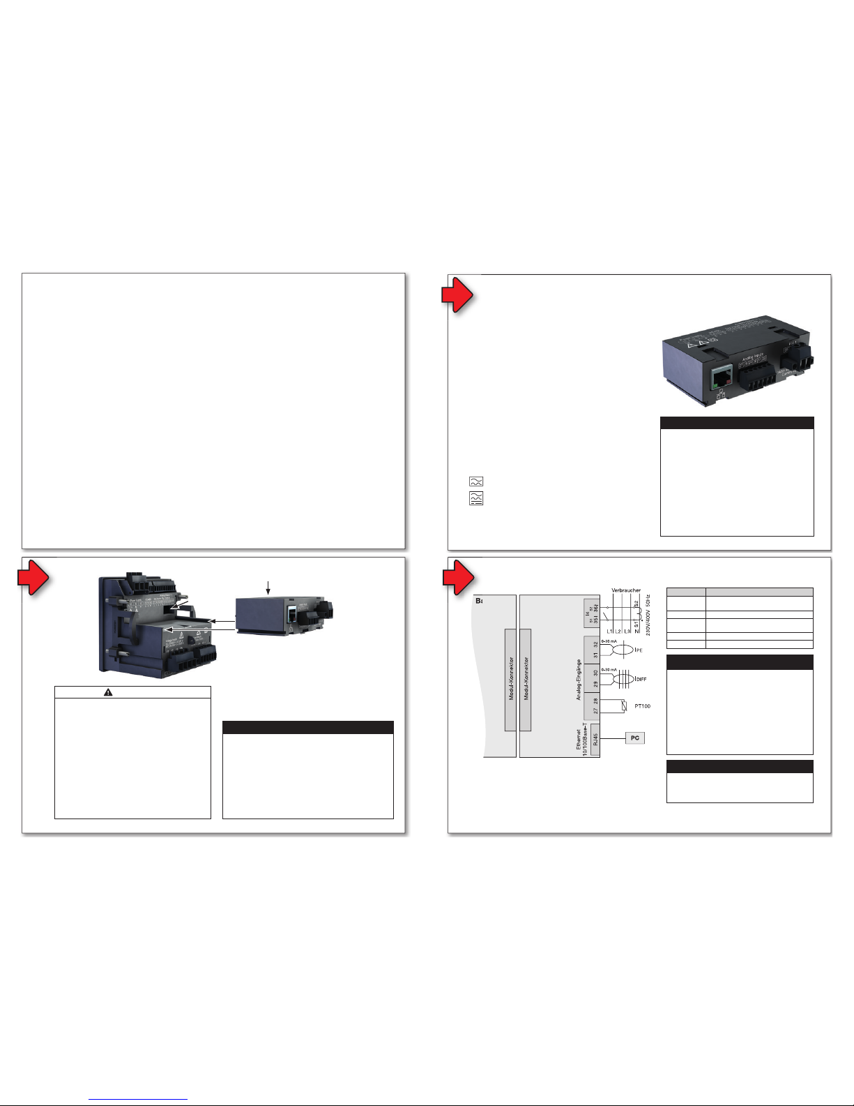
Anschlussvariante mit Klemmenbelegung
Basisgerät Modul
Abb. Anschlussvariante:
Basisgerät mit Modul 96-PA-RCM-EL
5
4
Abb. Basisgerät
Modul montieren:
1. Anlage (Basisgerät) spannungsfrei schalten!
2. Transportschutz vom Modul-Konnektor-Stecker
des Moduls und den Schutz der Modul-Konnektor-
Buchse des Basisgeräts entfernen!
3. Modul in die Nut auf der Rückseite des Basisgeräts
schieben und mit leichtem Druck in das Basisgerät
drücken, bis der Modul-Konnektor hörbar einrastet.
4. Spannung an die Anlage (Basisgerät) anlegen. Das
Basisgerät erkennt das Modul automatisch.
Montage
Modul-Konnektor-
Buchse
Modul-Konnektor-Stecker
Abb. Modul 96-PA-RCM-EL
(mit Ethernet-Schnittstelle)
ACHTUNG
Das Basisgerät erkennt beim Startvorgang das
Modul nicht!
Bei fehlender Kommunikation zum Modul, erfolgt keine
Unterstützung der Modul-Funktionen (z.B. Differenz-
strom oder DC-Leistung).
· Schalten Sie Ihre Anlage (das Basisgerät) span-
nungsfrei und prüfen Sie die Lage des RCM-
Moduls. Drücken Sie ggf. mit leichtem Druck das
Modul auf das Basisgerät, bis es hörbar einrastet.
· Starten Sie ggf. das Basisgerät neu.
· Führen die Maßnahmen nicht zum Ziel, wenden
Sie sich an unseren Support (www. janitza.de)!
VORSICHT
Sach- oder Personenschaden durch Nichtbe-
achtung der Montagehinweise!
Nichtbeachtung der Montagehinweise kann Ihr
Basisgerät mit Modul beschädigen oder zerstören
und bis hin zu Personenschäden führen.
· Beachten Sie die Montage-Hinweise Ihres
Basisgeräts.
· Schalten Sie vor der Montage des Moduls Ihr
Basisgerät spannungsfrei!
· Sorgen Sie in Ihrer Einbau-Umgebung für
ausreichende Luftzirkulation, bei hohen Umge-
bungstemperaturen ggf. für Kühlung.
· Entfernen Sie vor der Montage den Transport-
schutz vom Modul-Konnektor-Stecker des
Moduls und den Schutz der Modul-Konnektor-
Buchse des Basisgeräts!
· Senden Sie defekte Module zurück an den
Hersteller (vgl. Schritt „Demontage“).
Allgemeines
1
2
2
Sicherheit
Sicherheitshinweise
Die Installationsanleitung stellt kein vollständiges
Verzeichnis aller für den Betrieb des Geräts erfor-
derlichen Sicherheitsmaßnahmen dar.
Besondere Betriebsbedingungen können weitere
Maßnahmen erfordern. Die Installationsanleitung
enthält Hinweise, die Sie zu Ihrer persönlichen
Sicherheit und zur Vermeidung von Sachschäden
beachten müssen.
Verwendete Symbole auf dem Gerät:
Das zusätzliche Symbol auf dem
Gerät selbst deutet auf eine elekt-
rische Gefahr hin, die zu schweren
Verletzungen oder Tod führen
kann.
Das allgemeine Warnsymbol
macht Sie auf mögliche Verlet-
zungsgefahren aufmerksam.
Beachten Sie alle unter diesem
Symbol aufgeführten Hinweise, um
mögliche Verletzungen oder gar
Todesfälle zu vermeiden.
Sicherheitshinweise in der Installationsanleitung
sind durch ein Warndreieck hervorgehoben und je
nach Gefährdungsgrad wie folgt dargestellt:
Maßnahmen zur Sicherheit
Beim Betrieb elektrischer Geräte stehen zwangs-
läufi g bestimmte Teile dieser Geräte unter gefähr-
licher Spannung. Es können deshalb schwere
Körperverletzung oder Sachschäden auftreten,
wenn nicht fachgerecht gehandelt wird:
• Vor Anschluss von Verbindungen das Gerät,
• Gefährliche Spannungen können in allen
• Auch nach Abtrennen der Versorgungsspan-
• Betriebsmittel mit Stromwandlerkreisen nicht
• Die im Benutzerhandbuch und auf dem Typen-
• Beachten Sie Sicherheits- und Warnhinwei-
Haftungsausschluss
Die Beachtung der Informationsprodukte zu
den Geräten ist Voraussetzung für den sicheren
Betrieb und um angegebene Leistungsmerkma-
le und Produkteigenschaften zu erreichen. Für
Personen-, Sach - oder Vermögensschäden, die
durch Nichtachtung der Informationsprodukte
entstehen, übernimmt die Janitza electronics
GmbH keine Haftung. Sorgen Sie dafür, dass Ihre
Informationsprodukte leserlich zugänglich sind.
Weiterführende Dokumentationen, wie z. B.
Benutzerhandbücher zu den Basisgeräten und
Modulen, fi nden Sie auf unserer Website
www.janitza.de unter Support > Downloads.
Urheberrechtsvermerk
© 2018 - Janitza electronics GmbH - Lahnau.
Alle Rechte vorbehalten. Jede, auch auszugswei-
se, Vervielfältigung, Bearbeitung, Verbreitung und
sonstige Verwertung ist verboten.
Technische Änderungen vorbehalten
• Achten Sie darauf, dass Ihr Gerät mit der
Installationsanleitung übereinstimmt.
• Lesen und verstehen Sie zunächst produktbe-
gleitende Dokumente.
• Produktbegleitende Dokumente während der
gesamten Lebensdauer verfügbar halten und
gegebenenfalls an nachfolgende Benutzer
weitergeben.
• Bitte informieren Sie sich über Geräte-Revisio-
nen und die damit verbundenen Anpassungen
der produktbegleitenden Dokumentation auf
www.janitza.de.
Entsorgung
Bitte beachten Sie nationale Bestimmungen! Ent-
sorgen Sie gegebenenfalls einzelne Teile, je nach
Beschaffenheit und existierende länderspezifi sche
Vorschriften, z.B. als:
• Elektroschrott
• Kunststoffe
• Metalle
oder beauftragen Sie einen zertifi zierten
Entsorgungsbetrieb mit der Verschrottung.
Relevante Gesetze,
angewendete Normen und Richtlinien
Die von der Janitza electronics GmbH angewen-
deten Gesetze, Normen und Richtlinien für das
Gerät entnehmen Sie der Konformitätserklärung
auf unserer Website (www.janitza.de).
HINWEIS
Verweist auf Vorgänge bei denen die Gefahr von
Verletzungen oder Sachschäden nicht besteht.
ACHTUNG
Weist auf eine unmittelbar gefährliche Situation
hin, die bei Nichtbeachtung zu Sachschäden oder
Umweltschäden führen kann.
VORSICHT
Weist auf eine möglicherweise gefährliche
Situation hin, die zu leichten Verletzungen oder
Sachschäden führen kann.
WARNUNG
Weist auf eine möglicherweise gefährliche Situa-
tion hin, die zu schweren Verletzungen oder Tod
führen kann.
GEFAHR
Weist auf eine unmittelbar drohende Gefahr hin,
die zu schweren bzw. tödlichen Verletzungen führt.
Die PC-Verbindung des Basisgeräts mit Modul
gelingt über die
1. RS485-Schnittstelle
2. Ethernet-Schnittstelle (nur RCM-EL)
6
PC-Verbindung des Basisgeräts
Anschlussvariante mit Klemmenbelegung
Basisgerät Modul
96-PA-RCM-EL
Abb. Anschlussvariante:
Basisgerät mit Modul 96-PA-RCM-EL
Klemme
RJ45
Ethernet-Schnittstelle
(nur Modul 96-PA-RCM-EL)
27 / 28 Temperaturmessung
29 / 30 und
31 / 32
Differenzstrommessung mit Kabelbrucher-
kennung
oder 31 / 32 Spannungsmessung
35 / 36 Strommessung I4
5
HINWEIS
Ausführliche Informationen zur Spannungsmes-
sung, Strommessung und den Anschlussvarian-
ten fi nden Sie in der Installationsanleitung Ihres
Basisgeräts.
ACHTUNG
Unsachgemäßer Umgang kann das Modul
beschädigen und zu Sachschaden führen!
Die Kontakte des Modul-Konnektors können
verbiegen oder abbrechen und das Modul
zerstören.
· Kontakte des Modul-Konnektors niemals
berühren oder manipulieren!
· Den Modul-Konnektor-Stecker nie mit
Gewalt in die Buchse drücken!
· Schützen Sie beim Umgang, Transport und
bei der Lagerung des Moduls die Kontakte
des Modul-Konnektors!
4
Abb. Basisgerät
Modul montieren:
1. Anlage (Basisgerät) spannungsfrei schalten!
2. Transportschutz vom Modul-Konnektor-Stecker
des Moduls und den Schutz der Modul-KonnektorBuchse des Basisgeräts entfernen!
3. Modul in die Nut auf der Rückseite des Basisgeräts
schieben und mit leichtem Druck in das Basisgerät
drücken, bis der Modul-Konnektor hörbar einrastet.
4. Spannung an die Anlage (Basisgerät) anlegen. Das
Basisgerät erkennt das Modul automatisch.
Montage
Modul-KonnektorBuchse
Modul-Konnektor-Stecker
Abb. Modul 96-PA-RCM-EL
(mit Ethernet-Schnittstelle)
PC/GridVis
Anschluss des Basisgeräts
über die Ethernet-Schnittstelle
des Moduls 96-PA-RCM-EL.
ACHTUNG
Das Basisgerät erkennt beim Startvorgang das
Modul nicht!
Bei fehlender Kommunikation zum Modul, erfolgt keine
Unterstützung der Modul-Funktionen (z.B. Differenz-
strom oder DC-Leistung).
· Schalten Sie Ihre Anlage (das Basisgerät) span-
nungsfrei und prüfen Sie die Lage des RCMModuls. Drücken Sie ggf. mit leichtem Druck das
Modul auf das Basisgerät, bis es hörbar einrastet.
· Starten Sie ggf. das Basisgerät neu.
· Führen die Maßnahmen nicht zum Ziel, wenden
Sie sich an unseren Support (www. janitza.de)!
VORSICHT
Sach- oder Personenschaden durch Nichtbeachtung der Montagehinweise!
Nichtbeachtung der Montagehinweise kann Ihr
Basisgerät mit Modul beschädigen oder zerstören
und bis hin zu Personenschäden führen.
· Beachten Sie die Montage-Hinweise Ihres
Basisgeräts.
· Schalten Sie vor der Montage des Moduls Ihr
Basisgerät spannungsfrei!
· Sorgen Sie in Ihrer Einbau-Umgebung für
ausreichende Luftzirkulation, bei hohen Umgebungstemperaturen ggf. für Kühlung.
· Entfernen Sie vor der Montage den Transport-
schutz vom Modul-Konnektor-Stecker des
Moduls und den Schutz der Modul-KonnektorBuchse des Basisgeräts!
· Senden Sie defekte Module zurück an den
Hersteller (vgl. Schritt „Demontage“).
2
2
Sicherheit
Sicherheitshinweise
Die Installationsanleitung stellt kein vollständiges
Verzeichnis aller für den Betrieb des Geräts erfor-
derlichen Sicherheitsmaßnahmen dar.
Besondere Betriebsbedingungen können weitere
Maßnahmen erfordern. Die Installationsanleitung
enthält Hinweise, die Sie zu Ihrer persönlichen
Sicherheit und zur Vermeidung von Sachschäden
beachten müssen.
Verwendete Symbole auf dem Gerät:
Das zusätzliche Symbol auf dem
Gerät selbst deutet auf eine elekt-
rische Gefahr hin, die zu schweren
Verletzungen oder Tod führen
kann.
Das allgemeine Warnsymbol
macht Sie auf mögliche Verlet-
zungsgefahren aufmerksam.
Beachten Sie alle unter diesem
Symbol aufgeführten Hinweise, um
mögliche Verletzungen oder gar
Todesfälle zu vermeiden.
Sicherheitshinweise in der Installationsanleitung
sind durch ein Warndreieck hervorgehoben und je
nach Gefährdungsgrad wie folgt dargestellt:
Maßnahmen zur Sicherheit
Beim Betrieb elektrischer Geräte stehen zwangs-
läufi g bestimmte Teile dieser Geräte unter gefähr-
licher Spannung. Es können deshalb schwere
Körperverletzung oder Sachschäden auftreten,
wenn nicht fachgerecht gehandelt wird:
• Vor Anschluss von Verbindungen das Gerät,
am Schutzleiteranschluss, wenn vorhanden,
erden.
• Gefährliche Spannungen können in allen
mit der Spannungsversorgung verbundenen
Schaltungsteilen anstehen.
• Auch nach Abtrennen der Versorgungsspan-
nung können gefährliche Spannungen im
Gerät vorhanden sein (Kondensatorspeicher).
• Betriebsmittel mit Stromwandlerkreisen nicht
offen betreiben.
• Die im Benutzerhandbuch und auf dem Typen-
schild genannten Grenzwerte nicht überschrei-
ten! Dies ist auch bei der Prüfung und der
Inbetriebnahme zu beachten!
• Beachten Sie Sicherheits- und Warnhinwei-
se in den Dokumenten, die zu den Geräten
gehören!
Bestimmungsgemäße Verwendung
Die Module 96-PA-RCM und 96-PA-RCM-EL
WARNUNG
Verletzungsgefahr durch elektrische Spannung!
Schwere Körperverletzungen oder Tod können
erfolgen durch:
· Berühren von blanken oder abisolierten Adern,
die unter Spannung stehen.
· Berührungsgefährliche Eingänge des Geräts.
Vor Arbeitsbeginn an Ihrer Anlage:
· Die Anlage spannungsfrei schalten!
· Gegen Wiedereinschalten sichern!
· Spannungsfreiheit feststellen!
· Erden und Kurzschließen!
· Benachbarte, unter Spannung stehende
Teile abdecken oder abschranken!
HINWEIS
Verweist auf Vorgänge bei denen die Gefahr von
Verletzungen oder Sachschäden nicht besteht.
ACHTUNG
Weist auf eine unmittelbar gefährliche Situation
hin, die bei Nichtbeachtung zu Sachschäden oder
Umweltschäden führen kann.
VORSICHT
Weist auf eine möglicherweise gefährliche
Situation hin, die zu leichten Verletzungen oder
Sachschäden führen kann.
WARNUNG
Weist auf eine möglicherweise gefährliche Situa-
tion hin, die zu schweren Verletzungen oder Tod
führen kann.
GEFAHR
Weist auf eine unmittelbar drohende Gefahr hin,
die zu schweren bzw. tödlichen Verletzungen führt.
Eingangskontrolle
Der einwandfreie und sichere Betrieb der Geräte
und der RCM-Module setzen sachgemäßen
Transport, fachgerechte Lagerung, Aufstellung
und Montage sowie sorgfältige Bedienung und
Instandhaltung voraus.
Nehmen Sie das Aus- und Einpacken mit der üb-
lichen Sorgfalt ohne Gewaltanwendung und nur
unter Verwendung von geeignetem Werkzeug vor.
7
Die PC-Verbindung des Basisgeräts mit Modul
gelingt über die
1. RS485-Schnittstelle
Beschreibungen zum Anschluss über die
RS485-Schnittstelle des Basisgeräts mit
Modul und zur RS485-Busstruktur nach
dem Master-Slave-Prinzip, fi nden Sie in der
Dokumentation zu den Basisgeräten.
2. Ethernet-Schnittstelle (nur RCM-EL)
Um Daten zu konfi gurieren und auszulesen,
verbinden Sie Ihr Basisgerät über die Ethernet-
Schnittstelle des Moduls 96-PA-RCM-EL mit
dem PC (Software GridVis).
HINWEISE
Ihr Basisgerät mit Modul 96-PA-RCM-EL verfügt
zur Kommunikation über
· 1 Ethernet-Schnittstelle und
· 1 RS485-Schnittstelle (Feldbus)
die im Fenster Kommunikation eingestellt werden.
Bei der PC-Verbindung über Ethernet kann das Ba-
sisgerät mit Modul 96-PA-RCM-EL als Gateway
(Master) genutzt werden.
6
PC-Verbindung des Basisgeräts
ACHTUNG
Sachschaden durch falsche Netzwerkeinstel-
lungen.
Falsche Netzwerkeinstellungen können Störungen
im IT-Netzwerk verursachen!
Informieren Sie sich bei Ihrem Netzwerkad-
ministrator über die korrekten Netzwerk-
einstellungen für Ihr Gerät.
Anschlussvariante mit Klemmenbelegung
Basisgerät Modul
96-PA-RCM-EL
Abb. Anschlussvariante:
Basisgerät mit Modul 96-PA-RCM-EL
Klemme
RJ45
Ethernet-Schnittstelle
(nur Modul 96-PA-RCM-EL)
27 / 28 Temperaturmessung
29 / 30 und
31 / 32
Differenzstrommessung mit Kabelbrucher-
kennung
oder 31 / 32 Spannungsmessung
35 / 36 Strommessung I4
5
HINWEIS
Ausführliche Informationen zur Spannungsmessung, Strommessung und den Anschlussvarianten fi nden Sie in der Installationsanleitung Ihres
Basisgeräts.
ACHTUNG
Unsachgemäßer Umgang kann das Modul
beschädigen und zu Sachschaden führen!
Die Kontakte des Modul-Konnektors können
verbiegen oder abbrechen und das Modul
zerstören.
· Kontakte des Modul-Konnektors niemals
berühren oder manipulieren!
· Den Modul-Konnektor-Stecker nie mit
Gewalt in die Buchse drücken!
· Schützen Sie beim Umgang, Transport und
bei der Lagerung des Moduls die Kontakte
des Modul-Konnektors!
Qualifi ziertes Personal
Um Personen- und Sachschäden zu vermeiden,
darf nur qualifi ziertes Personal mit elektrotechni-
scher Ausbildung am Gerät arbeiten mit Kennt-
nissen
• der nationalen Unfallverhütungsvorschriften
• in Standards der Sicherheitstechnik
• in Installation, Inbetriebnahme und Betrieb des
Geräts.
Ethernet-Verbindung, z.B.
zum DHCP-Server oder PC
Abb. Rückseite Basisgerät mit
Modul 96-PA-RCM-EL
RS485
Ethernet
RS485
PC/GridVis
®
Basisgerät UMG 96-PA mit
Modul RCM-EL
UMG 96-PA
Anschluss des Basisgeräts
über die Ethernet-Schnittstelle
des Moduls 96-PA-RCM-EL.
Anschluss weiterer Geräte
nach dem Master-/Slave-Prinzip
Die Bedienung Ihres Basisgeräts mit Modul
96-PA-RCM oder 96-PA-RCM-EL erfolgt über
6 Funktionstasten für die
Bedienung und Tastenfunktionen
Page 3
3 / 10
Maßnahmen zur Sicherheit
Beim Betrieb elektrischer Geräte stehen zwangs-
läufi g bestimmte Teile dieser Geräte unter gefähr-
licher Spannung. Es können deshalb schwere
Körperverletzung oder Sachschäden auftreten,
wenn nicht fachgerecht gehandelt wird:
• Vor Anschluss von Verbindungen das Gerät,
am Schutzleiteranschluss, wenn vorhanden,
erden.
• Gefährliche Spannungen können in allen
mit der Spannungsversorgung verbundenen
Schaltungsteilen anstehen.
• Auch nach Abtrennen der Versorgungsspan-
nung können gefährliche Spannungen im
Gerät vorhanden sein (Kondensatorspeicher).
• Betriebsmittel mit Stromwandlerkreisen nicht
offen betreiben.
• Die im Benutzerhandbuch und auf dem Typen-
schild genannten Grenzwerte nicht überschrei-
ten! Dies ist auch bei der Prüfung und der
Inbetriebnahme zu beachten!
• Beachten Sie Sicherheits- und Warnhinwei-
se in den Dokumenten, die zu den Geräten
gehören!
Bestimmungsgemäße Verwendung
Die Module 96-PA-RCM und 96-PA-RCM-EL
• sind als Aufsteckmodule für das Basisgerät
UMG 96-PA in Schaltschränken und Installati-
onskleinverteilern bestimmt. Die Einbaulage ist
beliebig (Bitte beachten Sie die zum Basisge-
rät gehörende Dokumentation).
• dürfen nur auf spannungsfrei geschaltete
Basisgeräte montiert werden (siehe Schritt
„Montage“).
• sind nicht für den Einbau in Fahrzeuge
bestimmt! Der Einsatz des Basisgeräts mit
Modul in nicht ortsfesten Ausrüstungen gilt als
außergewöhnliche Umweltbedingung und ist
nur nach gesonderter Vereinbarung zulässig.
• sind nicht für den Einbau in Umgebungen mit
schädlichen Ölen, Säuren, Gasen, Dämpfen,
Stäuben, Strahlungen, usw. bestimmt.
WARNUNG
Verletzungsgefahr durch elektrische Spannung!
Schwere Körperverletzungen oder Tod können
erfolgen durch:
· Berühren von blanken oder abisolierten Adern,
die unter Spannung stehen.
· Berührungsgefährliche Eingänge des Geräts.
Vor Arbeitsbeginn an Ihrer Anlage:
· Die Anlage spannungsfrei schalten!
· Gegen Wiedereinschalten sichern!
· Spannungsfreiheit feststellen!
· Erden und Kurzschließen!
· Benachbarte, unter Spannung stehende
Teile abdecken oder abschranken!
Eingangskontrolle
Der einwandfreie und sichere Betrieb der Geräte
und der RCM-Module setzen sachgemäßen
Transport, fachgerechte Lagerung, Aufstellung
und Montage sowie sorgfältige Bedienung und
Instandhaltung voraus.
Nehmen Sie das Aus- und Einpacken mit der üb-
lichen Sorgfalt ohne Gewaltanwendung und nur
unter Verwendung von geeignetem Werkzeug vor.
Prüfen Sie:
• Geräte und Module durch Sichtkontrolle auf
einwandfreien mechanischen Zustand.
• den Lieferumfang (siehe Benutzerhandbuch)
auf Vollständigkeit bevor Sie mit der Montage
und Installation Ihrer Geräte beginnen.
Wenn anzunehmen ist, dass ein gefahrloser
Betrieb nicht mehr möglich ist, so setzen Sie Ihr
Basisgerät mit Modul unverzüglich außer Betrieb
und sichern es gegen unbeabsichtigte Inbetrieb-
nahme.
Es ist anzunehmen, dass ein gefahrloser Betrieb
unmöglich ist, wenn das Gerät mit Modul z.B.:
• sichtbare Beschädigungen aufweist,
• trotz intakter Netzversorgung nicht mehr
arbeitet,
• längere Zeit ungünstigen Verhältnissen (z.B.
Lagerung außerhalb der zulässigen Klimagren-
zen ohne Anpassung an das Raumklima, Be-
tauung o.Ä.) oder Transportbeanspruchungen
(z.B. Fall aus großer Höhe auch ohne sichtbare
äußere Beschädigung o.Ä..) ausgesetzt war.
7
Die PC-Verbindung des Basisgeräts mit Modul
gelingt über die
1. RS485-Schnittstelle
Beschreibungen zum Anschluss über die
RS485-Schnittstelle des Basisgeräts mit
Modul und zur RS485-Busstruktur nach
dem Master-Slave-Prinzip, fi nden Sie in der
Dokumentation zu den Basisgeräten.
2. Ethernet-Schnittstelle (nur RCM-EL)
Um Daten zu konfi gurieren und auszulesen,
verbinden Sie Ihr Basisgerät über die EthernetSchnittstelle des Moduls 96-PA-RCM-EL mit
dem PC (Software GridVis).
HINWEISE
Ihr Basisgerät mit Modul 96-PA-RCM-EL verfügt
zur Kommunikation über
· 1 Ethernet-Schnittstelle und
· 1 RS485-Schnittstelle (Feldbus)
die im Fenster Kommunikation eingestellt werden.
Bei der PC-Verbindung über Ethernet kann das Basisgerät mit Modul 96-PA-RCM-EL als Gateway
(Master) genutzt werden.
6
PC-Verbindung des Basisgeräts
ACHTUNG
Sachschaden durch falsche Netzwerkeinstellungen.
Falsche Netzwerkeinstellungen können Störungen
im IT-Netzwerk verursachen!
Informieren Sie sich bei Ihrem Netzwerkadministrator über die korrekten Netzwerkeinstellungen für Ihr Gerät.
Qualifi ziertes Personal
Um Personen- und Sachschäden zu vermeiden,
darf nur qualifi ziertes Personal mit elektrotechni-
scher Ausbildung am Gerät arbeiten mit Kennt-
nissen
• der nationalen Unfallverhütungsvorschriften
• in Standards der Sicherheitstechnik
• in Installation, Inbetriebnahme und Betrieb des
Geräts.
Ethernet-Verbindung, z.B.
zum DHCP-Server oder PC
Abb. Rückseite Basisgerät mit
Modul 96-PA-RCM-EL
RS485
Ethernet
RS485
PC/GridVis
®
Basisgerät UMG 96-PA mit
Modul RCM-EL
UMG 96-PA
Anschluss des Basisgeräts
über die Ethernet-Schnittstelle
des Moduls 96-PA-RCM-EL.
Anschluss weiterer Geräte
nach dem Master-/Slave-Prinzip
Die Bedienung Ihres Basisgeräts mit Modul
96-PA-RCM oder 96-PA-RCM-EL erfolgt über
6 Funktionstasten für die
• Auswahl von Messwertanzeigen.
• Navigation innerhalb der Menüs.
• Bearbeitung der Geräteeinstellungen.
Bedienung und Tastenfunktionen
Funktionstasten
Abb. Basisgerät - Messwertanzeige
HINWEIS
Nähere Informationen zur Bedienung, zu Anzeigen
und Tastenfunktionen fi nden Sie in der Installa-
tionsanleitung oder im Benutzerhandbuch Ihres
Basisgeräts.
Taste Funktion
• Menü anzeigen
• Menü verlassen
• Aktion abbrechen (ESC)
• Zur Anzeige Home wechseln
• Position wählen (nach links „
“)
• Menüpunkt oder Position wählen
(nach unten „
“)
• Ändern (Auswahl, Ziffer -1)
• Menüpunkt oder Position wählen
(nach oben „
“)
• Ändern (Auswahl, Ziffer +1)
• Position wählen (nach rechts „
“)
• Auswahl bestätigen (Enter)
Allgemeines
1
2
Janitza electronics GmbH
Vor dem Polstück 6
D-35633 Lahnau
Support Tel. +49 6441 9642-22
Fax +49 6441 9642-30
E-Mail: info@janitza.de
www.janitza.de
www.janitza.de
Dok.-Nr. 2.061.025.0b 12/2018 Art.-Nr. 33.03.374
English version:
see rear side
2
Sicherheit
Sicherheitshinweise
Die Installationsanleitung stellt kein vollständiges
Verzeichnis aller für den Betrieb des Geräts erfor-
derlichen Sicherheitsmaßnahmen dar.
Besondere Betriebsbedingungen können weitere
Maßnahmen erfordern. Die Installationsanleitung
enthält Hinweise, die Sie zu Ihrer persönlichen
Sicherheit und zur Vermeidung von Sachschäden
beachten müssen.
Verwendete Symbole auf dem Gerät:
Haftungsausschluss
Die Beachtung der Informationsprodukte zu
den Geräten ist Voraussetzung für den sicheren
Betrieb und um angegebene Leistungsmerkma-
le und Produkteigenschaften zu erreichen. Für
Personen-, Sach - oder Vermögensschäden, die
durch Nichtachtung der Informationsprodukte
entstehen, übernimmt die Janitza electronics
GmbH keine Haftung. Sorgen Sie dafür, dass Ihre
Informationsprodukte leserlich zugänglich sind.
Weiterführende Dokumentationen, wie z. B.
Benutzerhandbücher zu den Basisgeräten und
Modulen, fi nden Sie auf unserer Website
www.janitza.de unter Support > Downloads.
Urheberrechtsvermerk
© 2018 - Janitza electronics GmbH - Lahnau.
Alle Rechte vorbehalten. Jede, auch auszugswei-
se, Vervielfältigung, Bearbeitung, Verbreitung und
sonstige Verwertung ist verboten.
Technische Änderungen vorbehalten
• Achten Sie darauf, dass Ihr Gerät mit der
Installationsanleitung übereinstimmt.
• Lesen und verstehen Sie zunächst produktbe-
gleitende Dokumente.
• Produktbegleitende Dokumente während der
gesamten Lebensdauer verfügbar halten und
gegebenenfalls an nachfolgende Benutzer
weitergeben.
• Bitte informieren Sie sich über Geräte-Revisio-
nen und die damit verbundenen Anpassungen
der produktbegleitenden Dokumentation auf
www.janitza.de.
Entsorgung
Bitte beachten Sie nationale Bestimmungen! Ent-
sorgen Sie gegebenenfalls einzelne Teile, je nach
Beschaffenheit und existierende länderspezifi sche
Vorschriften, z.B. als:
• Elektroschrott
• Kunststoffe
• Metalle
oder beauftragen Sie einen zertifi zierten
Entsorgungsbetrieb mit der Verschrottung.
Relevante Gesetze,
angewendete Normen und Richtlinien
Die von der Janitza electronics GmbH angewen-
deten Gesetze, Normen und Richtlinien für das
Gerät entnehmen Sie der Konformitätserklärung
auf unserer Website (www.janitza.de).
Benutzerhandbuch:
RCM-Module
Erweiterungsmodule für das UMG 96-PA
Installationsanleitung
Modul 96-PA-RCM
Modul 96-PA-RCM-EL
Abb.
UMG 96-PA mit Modul 96-PA-RCM-EL (mit Ethernet-Schnittstelle)
3
Das RCM-Modul erweitert den Funktionsumfang
des Basisgeräts und ist in folgenden Varianten
erhältlich:
• Modul 96-PA-RCM
• Modul 96-PA-RCM-EL
(mit Ethernet-Schnittstelle).
Funktionen beider Modul-Varianten:
• Neutralleitermessung (I4).
• RCM-Messung oder DC-Messung.
• Temperaturmessung.
Beide Modul-Varianten eignen sich zur Überwa-
chung von:
• Differenzströmen (RCM) - Typ A, B und B+.
• AC-Strömen.
• DC-Strömen und pulsierenden DC-Strömen.
Das Basisgerät mit Modul misst Differenzströme
nach IEC/TR 60755 vom:
Typ A
Typ B und B+ (erweiterter Frequenzbereich)
Geräte-Kurzbeschreibung
HINWEISE
Zur Verwendung des Moduls benötigt das Basis-
gerät:
· mindestens Hardware-Version 4.
· die aktuelle Firmware-Version.
· Die Hardware-Version Ihres Basisgeräts fi nden
Sie auf dem Typenschild. Ausführliche Beschrei-
bungen hierzu, fi nden Sie im Benutzerhandbuch
Ihres Basisgeräts.
· Die Firmware-Version fi nden Sie in der Anzeige
Ihres Basisgeräts unter:
Menü > Konfi guration > System > Version.
Die aktuelle Firmware-Version für Ihr Basisgerät
fi nden Sie auf www.janitza.de.
Abb. Modul 96-PA-RCM-EL
(mit Ethernet-Schnittstelle)
9
Kommunikation über Ethernet-Schnittstelle (RCM-EL-Modul)
Das Basisgerät mit Modul 96-PA-RCM-EL
verfügt über 6 Arten der Adressvergabe für eine
Ethernet-Verbindung (TCP/IP):
1. Statisch
2. BOOTP
3. DHCP
4. Statisch Gratuitous ARP
5. BOOTP ARP Probe
6. DHCP ARP Probe
Standardeinstellung des Basisgeräts mit Modul 96-PA-RCM-EL ist DHCP!
Ethernet-Einstellungen konfi gurieren oder entnehmen Sie dem Fenster Kommunikation > Ethernet
(TCP/IP):
• Betätigen Sie im Fenster Home die Taste 1,
um das Menü zu öffnen.
• Wählen Sie mit den Tasten 3 oder 4 den
Menüpunkt Konfi guration und bestätigen Sie
mit Taste 6.
• Wählen Sie im Fenster Konfi guration mit den
Tasten 3 oder 4 den Eintrag Kommunikation
und bestätigen Sie mit Taste 6.
• Wählen Sie im Fenster Kommunikation mit den
Tasten 3 oder 4 den Eintrag Ethernet Konfi g
und bestätigen Sie mit Taste 6.
• Es erscheint das Fenster Kommunikation mit
den Ethernet-Einstellungen:
Abb. Fenster Kommunikation --> Ethernet-Konfi guration
Anschlussvariante mit Klemmenbelegung
Basisgerät Modul
Abb. Anschlussvariante:
Basisgerät mit Modul 96-PA-RCM-EL
5
4
Abb. Basisgerät
Modul montieren:
1. Anlage (Basisgerät) spannungsfrei schalten!
2. Transportschutz vom Modul-Konnektor-Stecker
des Moduls und den Schutz der Modul-Konnektor-
Buchse des Basisgeräts entfernen!
3. Modul in die Nut auf der Rückseite des Basisgeräts
schieben und mit leichtem Druck in das Basisgerät
drücken, bis der Modul-Konnektor hörbar einrastet.
4. Spannung an die Anlage (Basisgerät) anlegen. Das
Basisgerät erkennt das Modul automatisch.
Montage
Modul-Konnektor-
Buchse
Modul-Konnektor-Stecker
8
Abb. Modul 96-PA-RCM-EL
(mit Ethernet-Schnittstelle)
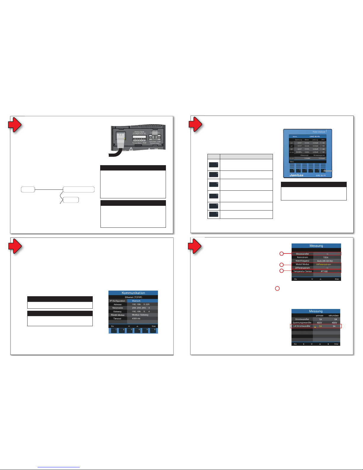
Modulrelevante Einstellungen
Im Fenster Messung Ihres Basisgeräts mit Modul
konfi gurieren Sie relevante Parameter für das Mo-
dul. Wechseln Sie dazu mit den Funktionstasten
in das Fenster Messung:
• Öffnen Sie das Menü durch Betätigen der
Taste 1 im Fenster Home.
• Wählen Sie mit den Tasten 3/4 den Menüpunkt
Konfi guration und bestätigen Sie mit Taste 6.
• Wählen Sie im Fenster Konfi guration mit den
Tasten 3/4 den Eintrag Messung und bestäti-
gen Sie mit Taste 6.
• Es erscheint das Fenster Messung mit folgen-
den Einstellungen für das RCM-Modul:
A. Messwandler für das Basisgerät (I1 bis I3)
und L4 Stromwandler (I4 - Neutralleiter-
messung).
B. Messwandler für den Modul-Modus Diffe-
renzstrom oder DC-Leistung.
C. Temperatur-Sensor.
Abb. Fenster Messung mit den L4-Stromwandler-Einstellungen des
RCM-Moduls (Standardeinstellung 5 /5 A).
B
Abb. Fenster Messung mit den Einstellungen für das RCM-Modul
L4 Stromwandler (I4 - Messung)
Im Eintrag Messwandler konfi gurieren Sie neben
den Strom- und Spannungswandlerverhältnissen
des Basisgeräts, das Stromwandlerverhältnis für
die L4 Strommessung (z.B. Neutralleitermes-
sung).
A
C
A
B
Modul-Modus
Der Eintrag Modul-Modus im Fenster Messung
dient der Umschaltung auf die Messmodi
1. Modul-Modus Differenzstrom
ACHTUNG
Das Basisgerät erkennt beim Startvorgang das
Modul nicht!
Bei fehlender Kommunikation zum Modul, erfolgt keine
Unterstützung der Modul-Funktionen (z.B. Differenz-
strom oder DC-Leistung).
· Schalten Sie Ihre Anlage (das Basisgerät) span-
nungsfrei und prüfen Sie die Lage des RCM-
Moduls. Drücken Sie ggf. mit leichtem Druck das
Modul auf das Basisgerät, bis es hörbar einrastet.
· Starten Sie ggf. das Basisgerät neu.
· Führen die Maßnahmen nicht zum Ziel, wenden
Sie sich an unseren Support (www. janitza.de)!
Konfi gurieren Sie, wie im Schritt Bedienung und
Tastenfunktionen beschrieben, Ihre Ethernet
(TCP/IP)-Einstellungen.
HINWEIS
Beschreibungen zur Adressvergabe fi nden Sie im
Benutzerhandbuch des Moduls.
HINWEIS
Informieren Sie sich bei Ihrem Netzwerkadministrator über die Ethernet-Netzwerkeinstellungen für
Ihr Gerät.
VORSICHT
Sach- oder Personenschaden durch Nichtbe-
achtung der Montagehinweise!
Nichtbeachtung der Montagehinweise kann Ihr
Basisgerät mit Modul beschädigen oder zerstören
und bis hin zu Personenschäden führen.
· Beachten Sie die Montage-Hinweise Ihres
Basisgeräts.
· Schalten Sie vor der Montage des Moduls Ihr
Basisgerät spannungsfrei!
· Sorgen Sie in Ihrer Einbau-Umgebung für
ausreichende Luftzirkulation, bei hohen Umge-
bungstemperaturen ggf. für Kühlung.
· Entfernen Sie vor der Montage den Transport-
schutz vom Modul-Konnektor-Stecker des
Moduls und den Schutz der Modul-Konnektor-
Buchse des Basisgeräts!
· Senden Sie defekte Module zurück an den
Hersteller (vgl. Schritt „Demontage“).
Allgemeines
1
2
2
Sicherheit
Sicherheitshinweise
Die Installationsanleitung stellt kein vollständiges
Verzeichnis aller für den Betrieb des Geräts erfor-
derlichen Sicherheitsmaßnahmen dar.
Besondere Betriebsbedingungen können weitere
Maßnahmen erfordern. Die Installationsanleitung
enthält Hinweise, die Sie zu Ihrer persönlichen
Sicherheit und zur Vermeidung von Sachschäden
beachten müssen.
Verwendete Symbole auf dem Gerät:
Das zusätzliche Symbol auf dem
Gerät selbst deutet auf eine elekt-
rische Gefahr hin, die zu schweren
Verletzungen oder Tod führen
kann.
Das allgemeine Warnsymbol
macht Sie auf mögliche Verlet-
zungsgefahren aufmerksam.
Beachten Sie alle unter diesem
Symbol aufgeführten Hinweise, um
mögliche Verletzungen oder gar
Todesfälle zu vermeiden.
Sicherheitshinweise in der Installationsanleitung
sind durch ein Warndreieck hervorgehoben und je
nach Gefährdungsgrad wie folgt dargestellt:
Maßnahmen zur Sicherheit
Beim Betrieb elektrischer Geräte stehen zwangs-
läufi g bestimmte Teile dieser Geräte unter gefähr-
licher Spannung. Es können deshalb schwere
Körperverletzung oder Sachschäden auftreten,
wenn nicht fachgerecht gehandelt wird:
Haftungsausschluss
Die Beachtung der Informationsprodukte zu
den Geräten ist Voraussetzung für den sicheren
Betrieb und um angegebene Leistungsmerkma-
le und Produkteigenschaften zu erreichen. Für
Personen-, Sach - oder Vermögensschäden, die
durch Nichtachtung der Informationsprodukte
entstehen, übernimmt die Janitza electronics
GmbH keine Haftung. Sorgen Sie dafür, dass Ihre
Informationsprodukte leserlich zugänglich sind.
Weiterführende Dokumentationen, wie z. B.
Benutzerhandbücher zu den Basisgeräten und
Modulen, fi nden Sie auf unserer Website
www.janitza.de unter Support > Downloads.
Urheberrechtsvermerk
© 2018 - Janitza electronics GmbH - Lahnau.
Alle Rechte vorbehalten. Jede, auch auszugswei-
se, Vervielfältigung, Bearbeitung, Verbreitung und
sonstige Verwertung ist verboten.
Technische Änderungen vorbehalten
• Achten Sie darauf, dass Ihr Gerät mit der
Installationsanleitung übereinstimmt.
• Lesen und verstehen Sie zunächst produktbe-
gleitende Dokumente.
• Produktbegleitende Dokumente während der
gesamten Lebensdauer verfügbar halten und
gegebenenfalls an nachfolgende Benutzer
weitergeben.
• Bitte informieren Sie sich über Geräte-Revisio-
nen und die damit verbundenen Anpassungen
der produktbegleitenden Dokumentation auf
www.janitza.de.
Entsorgung
Bitte beachten Sie nationale Bestimmungen! Ent-
sorgen Sie gegebenenfalls einzelne Teile, je nach
Beschaffenheit und existierende länderspezifi sche
Vorschriften, z.B. als:
• Elektroschrott
• Kunststoffe
• Metalle
oder beauftragen Sie einen zertifi zierten
Entsorgungsbetrieb mit der Verschrottung.
Relevante Gesetze,
angewendete Normen und Richtlinien
Die von der Janitza electronics GmbH angewen-
deten Gesetze, Normen und Richtlinien für das
Gerät entnehmen Sie der Konformitätserklärung
auf unserer Website (www.janitza.de).
HINWEIS
Verweist auf Vorgänge bei denen die Gefahr von
Verletzungen oder Sachschäden nicht besteht.
ACHTUNG
Weist auf eine unmittelbar gefährliche Situation
hin, die bei Nichtbeachtung zu Sachschäden oder
Umweltschäden führen kann.
VORSICHT
Weist auf eine möglicherweise gefährliche
Situation hin, die zu leichten Verletzungen oder
Sachschäden führen kann.
WARNUNG
Weist auf eine möglicherweise gefährliche Situa-
tion hin, die zu schweren Verletzungen oder Tod
führen kann.
GEFAHR
Weist auf eine unmittelbar drohende Gefahr hin,
die zu schweren bzw. tödlichen Verletzungen führt.
Die PC-Verbindung des Basisgeräts mit Modul
gelingt über die
9
6
PC-Verbindung des Basisgeräts
Anschlussvariante mit Klemmenbelegung
Basisgerät Modul
96-PA-RCM-EL
Abb. Anschlussvariante:
Basisgerät mit Modul 96-PA-RCM-EL
Klemme
RJ45
Ethernet-Schnittstelle
(nur Modul 96-PA-RCM-EL)
27 / 28 Temperaturmessung
29 / 30 und
31 / 32
Differenzstrommessung mit Kabelbrucher-
kennung
oder 31 / 32 Spannungsmessung
35 / 36 Strommessung I4
5
HINWEIS
Ausführliche Informationen zur Spannungsmes-
sung, Strommessung und den Anschlussvarian-
ten fi nden Sie in der Installationsanleitung Ihres
Basisgeräts.
ACHTUNG
Unsachgemäßer Umgang kann das Modul
beschädigen und zu Sachschaden führen!
Die Kontakte des Modul-Konnektors können
verbiegen oder abbrechen und das Modul
zerstören.
· Kontakte des Modul-Konnektors niemals
berühren oder manipulieren!
· Den Modul-Konnektor-Stecker nie mit
Gewalt in die Buchse drücken!
· Schützen Sie beim Umgang, Transport und
bei der Lagerung des Moduls die Kontakte
des Modul-Konnektors!
4
Abb. Basisgerät
Modul montieren:
1. Anlage (Basisgerät) spannungsfrei schalten!
2. Transportschutz vom Modul-Konnektor-Stecker
des Moduls und den Schutz der Modul-Konnektor-
Buchse des Basisgeräts entfernen!
3. Modul in die Nut auf der Rückseite des Basisgeräts
schieben und mit leichtem Druck in das Basisgerät
drücken, bis der Modul-Konnektor hörbar einrastet.
4. Spannung an die Anlage (Basisgerät) anlegen. Das
Basisgerät erkennt das Modul automatisch.
Montage
Modul-Konnektor-
Buchse
Modul-Konnektor-Stecker
Abb. Modul 96-PA-RCM-EL
(mit Ethernet-Schnittstelle)
PC/GridVis
Anschluss des Basisgeräts
über die Ethernet-Schnittstelle
des Moduls 96-PA-RCM-EL.
Modulrelevante Einstellungen
Im Fenster Messung Ihres Basisgeräts mit Modul
konfi gurieren Sie relevante Parameter für das Modul. Wechseln Sie dazu mit den Funktionstasten
in das Fenster Messung:
• Öffnen Sie das Menü durch Betätigen der
Taste 1 im Fenster Home.
• Wählen Sie mit den Tasten 3/4 den Menüpunkt
Konfi guration und bestätigen Sie mit Taste 6.
• Wählen Sie im Fenster Konfi guration mit den
Tasten 3/4 den Eintrag Messung und bestätigen Sie mit Taste 6.
• Es erscheint das Fenster Messung mit folgenden Einstellungen für das RCM-Modul:
A. Messwandler für das Basisgerät (I1 bis I3)
und L4 Stromwandler (I4 - Neutralleitermessung).
B. Messwandler für den Modul-Modus Diffe-
renzstrom oder DC-Leistung.
C. Temperatur-Sensor.
Abb. Fenster Messung mit den L4-Stromwandler-Einstellungen des
RCM-Moduls (Standardeinstellung 5 /5 A).
B
Abb. Fenster Messung mit den Einstellungen für das RCM-Modul
L4 Stromwandler (I4 - Messung)
Im Eintrag Messwandler konfi gurieren Sie neben
den Strom- und Spannungswandlerverhältnissen
des Basisgeräts, das Stromwandlerverhältnis für
die L4 Strommessung (z.B. Neutralleitermes-
sung).
A
C
A
2. Modul-Modus DC-Leistung
Abb. Fenster Anzeige „Differenzstrom“ mit den Einstellungen der
Parameter für den Messmodi Differenzstrom.
B
Modul-Modus
Der Eintrag Modul-Modus im Fenster Messung
dient der Umschaltung auf die Messmodi
1. Differenzstrom oder
2. DC-Leistung.
1. Modul-Modus Differenzstrom
• Wählen Sie im Fenster Messung den Modul-
Modus Differenzstrom.
• Wählen Sie anschließend den Eintrag Diffe-
renzstrom und betätigen Sie Taste 6 Enter.
• Es erscheint das Fenster Anzeige „Differenz-
strom“ mit den einzustellenden Parametern:
1
2
3
4
HINWEISE
Der Strommesseingang I4 des Basisgeräts mit
Modul:
· ist nur für eine Strommessung über Strom-
wandler zugelassen.
· ist für den Anschluss von Stromwandlern mit
Sekundärströmen von ../1 A und ../5 A ausge-
legt.
· hat als Standard das Stromwandlerverhältnis
5/5 A eingestellt.
· misst keine Gleichströme.
Aufgrund des fehlenden Multiplikators mit einer
Spannung erfolgt beim Strommesseingang I4 nur
eine Scheinstrommessung. Leistungsmessungen
über diesen Eingang sind daher nicht möglich. Für
den Strommesseingang kann kein Anschlusssche-
ma konfi guriert werden.
ACHTUNG
Das Basisgerät erkennt beim Startvorgang das
Modul nicht!
Bei fehlender Kommunikation zum Modul, erfolgt keine
Unterstützung der Modul-Funktionen (z.B. Differenz-
strom oder DC-Leistung).
· Schalten Sie Ihre Anlage (das Basisgerät) span-
nungsfrei und prüfen Sie die Lage des RCM-
Moduls. Drücken Sie ggf. mit leichtem Druck das
Modul auf das Basisgerät, bis es hörbar einrastet.
· Starten Sie ggf. das Basisgerät neu.
· Führen die Maßnahmen nicht zum Ziel, wenden
Sie sich an unseren Support (www. janitza.de)!
VORSICHT
Sach- oder Personenschaden durch Nichtbe-
achtung der Montagehinweise!
Nichtbeachtung der Montagehinweise kann Ihr
Basisgerät mit Modul beschädigen oder zerstören
und bis hin zu Personenschäden führen.
· Beachten Sie die Montage-Hinweise Ihres
Basisgeräts.
· Schalten Sie vor der Montage des Moduls Ihr
Basisgerät spannungsfrei!
· Sorgen Sie in Ihrer Einbau-Umgebung für
ausreichende Luftzirkulation, bei hohen Umge-
bungstemperaturen ggf. für Kühlung.
· Entfernen Sie vor der Montage den Transport-
schutz vom Modul-Konnektor-Stecker des
Moduls und den Schutz der Modul-Konnektor-
Buchse des Basisgeräts!
· Senden Sie defekte Module zurück an den
Hersteller (vgl. Schritt „Demontage“).
Bestimmungsgemäße Verwendung
Die Module 96-PA-RCM und 96-PA-RCM-EL
• sind als Aufsteckmodule für das Basisgerät
UMG 96-PA in Schaltschränken und Installati-
onskleinverteilern bestimmt. Die Einbaulage ist
beliebig (Bitte beachten Sie die zum Basisge-
rät gehörende Dokumentation).
• dürfen nur auf spannungsfrei geschaltete
Basisgeräte montiert werden (siehe Schritt
„Montage“).
• sind nicht für den Einbau in Fahrzeuge
bestimmt! Der Einsatz des Basisgeräts mit
Modul in nicht ortsfesten Ausrüstungen gilt als
außergewöhnliche Umweltbedingung und ist
nur nach gesonderter Vereinbarung zulässig.
• sind nicht für den Einbau in Umgebungen mit
schädlichen Ölen, Säuren, Gasen, Dämpfen,
Stäuben, Strahlungen, usw. bestimmt.
Eingangskontrolle
Der einwandfreie und sichere Betrieb der Geräte
und der RCM-Module setzen sachgemäßen
Transport, fachgerechte Lagerung, Aufstellung
und Montage sowie sorgfältige Bedienung und
Instandhaltung voraus.
Nehmen Sie das Aus- und Einpacken mit der üb-
lichen Sorgfalt ohne Gewaltanwendung und nur
unter Verwendung von geeignetem Werkzeug vor.
Prüfen Sie:
• Geräte und Module durch Sichtkontrolle auf
einwandfreien mechanischen Zustand.
• den Lieferumfang (siehe Benutzerhandbuch)
auf Vollständigkeit bevor Sie mit der Montage
und Installation Ihrer Geräte beginnen.
Wenn anzunehmen ist, dass ein gefahrloser
Betrieb nicht mehr möglich ist, so setzen Sie Ihr
Basisgerät mit Modul unverzüglich außer Betrieb
und sichern es gegen unbeabsichtigte Inbetrieb-
nahme.
Es ist anzunehmen, dass ein gefahrloser Betrieb
unmöglich ist, wenn das Gerät mit Modul z.B.:
• sichtbare Beschädigungen aufweist,
• trotz intakter Netzversorgung nicht mehr
arbeitet,
• längere Zeit ungünstigen Verhältnissen (z.B.
Lagerung außerhalb der zulässigen Klimagren-
zen ohne Anpassung an das Raumklima, Be-
tauung o.Ä.) oder Transportbeanspruchungen
(z.B. Fall aus großer Höhe auch ohne sichtbare
äußere Beschädigung o.Ä..) ausgesetzt war.
7
Die Bedienung Ihres Basisgeräts mit Modul
96-PA-RCM oder 96-PA-RCM-EL erfolgt über
6 Funktionstasten für die
• Auswahl von Messwertanzeigen.
• Navigation innerhalb der Menüs.
• Bearbeitung der Geräteeinstellungen.
Bedienung und Tastenfunktionen
Funktionstasten
Abb. Basisgerät - Messwertanzeige
HINWEIS
Nähere Informationen zur Bedienung, zu Anzeigen
und Tastenfunktionen fi nden Sie in der Installationsanleitung oder im Benutzerhandbuch Ihres
Basisgeräts.
Taste Funktion
• Menü anzeigen
• Menü verlassen
• Aktion abbrechen (ESC)
• Zur Anzeige Home wechseln
• Position wählen (nach links „“)
• Menüpunkt oder Position wählen
(nach unten „“)
• Ändern (Auswahl, Ziffer -1)
• Menüpunkt oder Position wählen
(nach oben „“)
• Ändern (Auswahl, Ziffer +1)
• Position wählen (nach rechts „“)
• Auswahl bestätigen (Enter)
Page 4

4 / 10
2
2
Sicherheit
Sicherheitshinweise
Die Installationsanleitung stellt kein vollständiges
Verzeichnis aller für den Betrieb des Geräts erfor-
derlichen Sicherheitsmaßnahmen dar.
Besondere Betriebsbedingungen können weitere
Maßnahmen erfordern. Die Installationsanleitung
enthält Hinweise, die Sie zu Ihrer persönlichen
Sicherheit und zur Vermeidung von Sachschäden
beachten müssen.
Verwendete Symbole auf dem Gerät:
Das zusätzliche Symbol auf dem
Gerät selbst deutet auf eine elekt-
rische Gefahr hin, die zu schweren
Verletzungen oder Tod führen
kann.
Das allgemeine Warnsymbol
macht Sie auf mögliche Verlet-
zungsgefahren aufmerksam.
Beachten Sie alle unter diesem
Symbol aufgeführten Hinweise, um
mögliche Verletzungen oder gar
Todesfälle zu vermeiden.
Sicherheitshinweise in der Installationsanleitung
sind durch ein Warndreieck hervorgehoben und je
nach Gefährdungsgrad wie folgt dargestellt:
Maßnahmen zur Sicherheit
Beim Betrieb elektrischer Geräte stehen zwangs-
läufi g bestimmte Teile dieser Geräte unter gefähr-
licher Spannung. Es können deshalb schwere
Körperverletzung oder Sachschäden auftreten,
wenn nicht fachgerecht gehandelt wird:
• Vor Anschluss von Verbindungen das Gerät,
am Schutzleiteranschluss, wenn vorhanden,
erden.
• Gefährliche Spannungen können in allen
mit der Spannungsversorgung verbundenen
Schaltungsteilen anstehen.
• Auch nach Abtrennen der Versorgungsspan-
nung können gefährliche Spannungen im
Gerät vorhanden sein (Kondensatorspeicher).
• Betriebsmittel mit Stromwandlerkreisen nicht
offen betreiben.
• Die im Benutzerhandbuch und auf dem Typen-
schild genannten Grenzwerte nicht überschrei-
ten! Dies ist auch bei der Prüfung und der
Inbetriebnahme zu beachten!
• Beachten Sie Sicherheits- und Warnhinwei-
se in den Dokumenten, die zu den Geräten
gehören!
Bestimmungsgemäße Verwendung
Die Module 96-PA-RCM und 96-PA-RCM-EL
WARNUNG
Verletzungsgefahr durch elektrische Spannung!
Schwere Körperverletzungen oder Tod können
erfolgen durch:
· Berühren von blanken oder abisolierten Adern,
die unter Spannung stehen.
· Berührungsgefährliche Eingänge des Geräts.
Vor Arbeitsbeginn an Ihrer Anlage:
· Die Anlage spannungsfrei schalten!
· Gegen Wiedereinschalten sichern!
· Spannungsfreiheit feststellen!
· Erden und Kurzschließen!
· Benachbarte, unter Spannung stehende
Teile abdecken oder abschranken!
HINWEIS
Verweist auf Vorgänge bei denen die Gefahr von
Verletzungen oder Sachschäden nicht besteht.
ACHTUNG
Weist auf eine unmittelbar gefährliche Situation
hin, die bei Nichtbeachtung zu Sachschäden oder
Umweltschäden führen kann.
VORSICHT
Weist auf eine möglicherweise gefährliche
Situation hin, die zu leichten Verletzungen oder
Sachschäden führen kann.
WARNUNG
Weist auf eine möglicherweise gefährliche Situa-
tion hin, die zu schweren Verletzungen oder Tod
führen kann.
GEFAHR
Weist auf eine unmittelbar drohende Gefahr hin,
die zu schweren bzw. tödlichen Verletzungen führt.
Eingangskontrolle
Der einwandfreie und sichere Betrieb der Geräte
und der RCM-Module setzen sachgemäßen
Transport, fachgerechte Lagerung, Aufstellung
und Montage sowie sorgfältige Bedienung und
Instandhaltung voraus.
Nehmen Sie das Aus- und Einpacken mit der üb-
lichen Sorgfalt ohne Gewaltanwendung und nur
unter Verwendung von geeignetem Werkzeug vor.
7
Die PC-Verbindung des Basisgeräts mit Modul
gelingt über die
1. RS485-Schnittstelle
Beschreibungen zum Anschluss über die
RS485-Schnittstelle des Basisgeräts mit
Modul und zur RS485-Busstruktur nach
dem Master-Slave-Prinzip, fi nden Sie in der
Dokumentation zu den Basisgeräten.
2. Ethernet-Schnittstelle (nur RCM-EL)
Um Daten zu konfi gurieren und auszulesen,
verbinden Sie Ihr Basisgerät über die Ethernet-
Schnittstelle des Moduls 96-PA-RCM-EL mit
dem PC (Software GridVis).
HINWEISE
Ihr Basisgerät mit Modul 96-PA-RCM-EL verfügt
zur Kommunikation über
· 1 Ethernet-Schnittstelle und
· 1 RS485-Schnittstelle (Feldbus)
die im Fenster Kommunikation eingestellt werden.
Bei der PC-Verbindung über Ethernet kann das Ba-
sisgerät mit Modul 96-PA-RCM-EL als Gateway
(Master) genutzt werden.
6
PC-Verbindung des Basisgeräts
ACHTUNG
Sachschaden durch falsche Netzwerkeinstel-
lungen.
Falsche Netzwerkeinstellungen können Störungen
im IT-Netzwerk verursachen!
Informieren Sie sich bei Ihrem Netzwerkad-
ministrator über die korrekten Netzwerk-
einstellungen für Ihr Gerät.
Anschlussvariante mit Klemmenbelegung
Basisgerät Modul
96-PA-RCM-EL
Abb. Anschlussvariante:
Basisgerät mit Modul 96-PA-RCM-EL
Klemme
RJ45
Ethernet-Schnittstelle
(nur Modul 96-PA-RCM-EL)
27 / 28 Temperaturmessung
29 / 30 und
31 / 32
Differenzstrommessung mit Kabelbrucher-
kennung
oder 31 / 32 Spannungsmessung
35 / 36 Strommessung I4
5
HINWEIS
Ausführliche Informationen zur Spannungsmes-
sung, Strommessung und den Anschlussvarian-
ten fi nden Sie in der Installationsanleitung Ihres
Basisgeräts.
ACHTUNG
Unsachgemäßer Umgang kann das Modul
beschädigen und zu Sachschaden führen!
Die Kontakte des Modul-Konnektors können
verbiegen oder abbrechen und das Modul
zerstören.
· Kontakte des Modul-Konnektors niemals
berühren oder manipulieren!
· Den Modul-Konnektor-Stecker nie mit
Gewalt in die Buchse drücken!
· Schützen Sie beim Umgang, Transport und
bei der Lagerung des Moduls die Kontakte
des Modul-Konnektors!
Qualifi ziertes Personal
Um Personen- und Sachschäden zu vermeiden,
darf nur qualifi ziertes Personal mit elektrotechni-
scher Ausbildung am Gerät arbeiten mit Kennt-
nissen
• der nationalen Unfallverhütungsvorschriften
• in Standards der Sicherheitstechnik
• in Installation, Inbetriebnahme und Betrieb des
Geräts.
Ethernet-Verbindung, z.B.
zum DHCP-Server oder PC
Abb. Rückseite Basisgerät mit
Modul 96-PA-RCM-EL
RS485
Ethernet
RS485
PC/GridVis
®
Basisgerät UMG 96-PA mit
Modul RCM-EL
UMG 96-PA
Anschluss des Basisgeräts
über die Ethernet-Schnittstelle
des Moduls 96-PA-RCM-EL.
Anschluss weiterer Geräte
nach dem Master-/Slave-Prinzip
Die Bedienung Ihres Basisgeräts mit Modul
96-PA-RCM oder 96-PA-RCM-EL erfolgt über
6 Funktionstasten für die
Bedienung und Tastenfunktionen
2. Modul-Modus DC-Leistung
• Wählen Sie im Fenster Messung den Modul-
Modus DC-Leistung.
• Wählen Sie anschließend den Eintrag DC-
Leistung und betätigen Sie Taste 6 Enter.
• Es erscheint das Fenster Anzeige „DC-Leis-
tung“ mit den einzustellenden Parametern:
Num.
DC-Leistung-
Parameter
Einstellungen
1
Analog CH 1 Typ,
I5 Klemme 29/30
Geeignete Wandlertypen:
·0 .. 20 mA
·4 .. 20 mA
2
Analog CH 2 Typ,
I6/U6
1)
Klemme 31/32
Geeignete Wandlertypen:
·0 .. 20 mA
·4 .. 20 mA
3
Messwandler-
verhältnisse
2)
·Stromwandler CH 1 - Prim. und Sek.
·Stromwandler CH 2 - Prim. und Sek.
4
Kabelbruch-
erkennung
Konfi gurierbar in der Software GridVis
®
und im Modbus-Editor (Basisgerät).
1
2
3
4
Abb. Fenster Anzeige „Differenzstrom“ mit den Einstellungen der
Parameter für den Messmodi Differenzstrom.
B
Modul-Modus
Der Eintrag Modul-Modus im Fenster Messung
dient der Umschaltung auf die Messmodi
1. Differenzstrom oder
2. DC-Leistung.
Num.
Differenzstrom-
Parameter
Einstellungen
1
Analog CH 1 Typ,
I5 Klemme 29/30
Geeignete Wandlertypen:
·AC (0 .. 30 mArms)
·0 .. 20 mA
·4 .. 20 mA
2
Analog CH 2 Typ,
I6 Klemme 31/32
Geeignete Wandlertypen:
·AC (0 .. 30 mArms)
·0 .. 20 mA
·4 .. 20 mA
3
Messwandler-
verhältnisse
·Stromwandler CH 1 - Prim. und Sek.
·Stromwandler CH 2 - Prim. und Sek.
4
Kabelbruch-
erkennung
Konfi gurierbar in der Software GridVis
®
und im Modbus-Editor (Basisgerät).
1. Modul-Modus Differenzstrom
• Wählen Sie im Fenster Messung den ModulModus Differenzstrom.
• Wählen Sie anschließend den Eintrag Differenzstrom und betätigen Sie Taste 6 Enter.
• Es erscheint das Fenster Anzeige „Differenz-
strom“ mit den einzustellenden Parametern:
1
2
3
4
HINWEISE
Der Strommesseingang I4 des Basisgeräts mit
Modul:
· ist nur für eine Strommessung über Stromwandler zugelassen.
· ist für den Anschluss von Stromwandlern mit
Sekundärströmen von ../1 A und ../5 A ausgelegt.
· hat als Standard das Stromwandlerverhältnis
5/5 A eingestellt.
· misst keine Gleichströme.
Aufgrund des fehlenden Multiplikators mit einer
Spannung erfolgt beim Strommesseingang I4 nur
eine Scheinstrommessung. Leistungsmessungen
über diesen Eingang sind daher nicht möglich. Für
den Strommesseingang kann kein Anschlussschema konfi guriert werden.
C
Temperatur-Sensor
Abb. Fenster Anzeige „DC-Leistung“ mit den Einstellungen der
Parameter für den Messmodi DC-Leistung.
1) Bei der DC-Leistungsmessung wird aus den Eingängen I5 und I6
(U6) eine Leistung ermittelt. Eine Spannung (U6) wird durch einen
aktiven Stromwandler in ein Stromsignal gewandelt. Das Stromsig-
nal verhält sich proportional zum Wert der Eingangsspannung.
2) Für die Einstellung des Wandlertyps 0 .. 20 mA bei CH2, konfi gu-
rieren Sie für das Messwandlerverhältnis eine Primärspannung und
einen proportionalen Sekundärstrom.
Maßnahmen zur Sicherheit
Beim Betrieb elektrischer Geräte stehen zwangs-
läufi g bestimmte Teile dieser Geräte unter gefähr-
licher Spannung. Es können deshalb schwere
Körperverletzung oder Sachschäden auftreten,
wenn nicht fachgerecht gehandelt wird:
• Vor Anschluss von Verbindungen das Gerät,
am Schutzleiteranschluss, wenn vorhanden,
erden.
• Gefährliche Spannungen können in allen
mit der Spannungsversorgung verbundenen
Schaltungsteilen anstehen.
• Auch nach Abtrennen der Versorgungsspan-
nung können gefährliche Spannungen im
Gerät vorhanden sein (Kondensatorspeicher).
• Betriebsmittel mit Stromwandlerkreisen nicht
offen betreiben.
• Die im Benutzerhandbuch und auf dem Typen-
schild genannten Grenzwerte nicht überschrei-
ten! Dies ist auch bei der Prüfung und der
Inbetriebnahme zu beachten!
• Beachten Sie Sicherheits- und Warnhinwei-
se in den Dokumenten, die zu den Geräten
gehören!
Bestimmungsgemäße Verwendung
Die Module 96-PA-RCM und 96-PA-RCM-EL
• sind als Aufsteckmodule für das Basisgerät
UMG 96-PA in Schaltschränken und Installati-
onskleinverteilern bestimmt. Die Einbaulage ist
beliebig (Bitte beachten Sie die zum Basisge-
rät gehörende Dokumentation).
• dürfen nur auf spannungsfrei geschaltete
Basisgeräte montiert werden (siehe Schritt
„Montage“).
• sind nicht für den Einbau in Fahrzeuge
bestimmt! Der Einsatz des Basisgeräts mit
Modul in nicht ortsfesten Ausrüstungen gilt als
außergewöhnliche Umweltbedingung und ist
nur nach gesonderter Vereinbarung zulässig.
• sind nicht für den Einbau in Umgebungen mit
schädlichen Ölen, Säuren, Gasen, Dämpfen,
Stäuben, Strahlungen, usw. bestimmt.
WARNUNG
Verletzungsgefahr durch elektrische Spannung!
Schwere Körperverletzungen oder Tod können
erfolgen durch:
· Berühren von blanken oder abisolierten Adern,
die unter Spannung stehen.
· Berührungsgefährliche Eingänge des Geräts.
Vor Arbeitsbeginn an Ihrer Anlage:
· Die Anlage spannungsfrei schalten!
· Gegen Wiedereinschalten sichern!
· Spannungsfreiheit feststellen!
· Erden und Kurzschließen!
· Benachbarte, unter Spannung stehende
Teile abdecken oder abschranken!
Eingangskontrolle
Der einwandfreie und sichere Betrieb der Geräte
und der RCM-Module setzen sachgemäßen
Transport, fachgerechte Lagerung, Aufstellung
und Montage sowie sorgfältige Bedienung und
Instandhaltung voraus.
Nehmen Sie das Aus- und Einpacken mit der üb-
lichen Sorgfalt ohne Gewaltanwendung und nur
unter Verwendung von geeignetem Werkzeug vor.
Prüfen Sie:
• Geräte und Module durch Sichtkontrolle auf
einwandfreien mechanischen Zustand.
• den Lieferumfang (siehe Benutzerhandbuch)
auf Vollständigkeit bevor Sie mit der Montage
und Installation Ihrer Geräte beginnen.
Wenn anzunehmen ist, dass ein gefahrloser
Betrieb nicht mehr möglich ist, so setzen Sie Ihr
Basisgerät mit Modul unverzüglich außer Betrieb
und sichern es gegen unbeabsichtigte Inbetrieb-
nahme.
Es ist anzunehmen, dass ein gefahrloser Betrieb
unmöglich ist, wenn das Gerät mit Modul z.B.:
• sichtbare Beschädigungen aufweist,
• trotz intakter Netzversorgung nicht mehr
arbeitet,
• längere Zeit ungünstigen Verhältnissen (z.B.
Lagerung außerhalb der zulässigen Klimagren-
zen ohne Anpassung an das Raumklima, Be-
tauung o.Ä.) oder Transportbeanspruchungen
(z.B. Fall aus großer Höhe auch ohne sichtbare
äußere Beschädigung o.Ä..) ausgesetzt war.
7
Die PC-Verbindung des Basisgeräts mit Modul
gelingt über die
1. RS485-Schnittstelle
Beschreibungen zum Anschluss über die
RS485-Schnittstelle des Basisgeräts mit
Modul und zur RS485-Busstruktur nach
dem Master-Slave-Prinzip, fi nden Sie in der
Dokumentation zu den Basisgeräten.
2. Ethernet-Schnittstelle (nur RCM-EL)
Um Daten zu konfi gurieren und auszulesen,
verbinden Sie Ihr Basisgerät über die Ethernet-
Schnittstelle des Moduls 96-PA-RCM-EL mit
dem PC (Software GridVis).
HINWEISE
Ihr Basisgerät mit Modul 96-PA-RCM-EL verfügt
zur Kommunikation über
· 1 Ethernet-Schnittstelle und
· 1 RS485-Schnittstelle (Feldbus)
die im Fenster Kommunikation eingestellt werden.
Bei der PC-Verbindung über Ethernet kann das Ba-
sisgerät mit Modul 96-PA-RCM-EL als Gateway
(Master) genutzt werden.
6
PC-Verbindung des Basisgeräts
ACHTUNG
Sachschaden durch falsche Netzwerkeinstel-
lungen.
Falsche Netzwerkeinstellungen können Störungen
im IT-Netzwerk verursachen!
Informieren Sie sich bei Ihrem Netzwerkad-
ministrator über die korrekten Netzwerk-
einstellungen für Ihr Gerät.
Qualifi ziertes Personal
Um Personen- und Sachschäden zu vermeiden,
darf nur qualifi ziertes Personal mit elektrotechni-
scher Ausbildung am Gerät arbeiten mit Kennt-
nissen
• der nationalen Unfallverhütungsvorschriften
• in Standards der Sicherheitstechnik
• in Installation, Inbetriebnahme und Betrieb des
Geräts.
Ethernet-Verbindung, z.B.
zum DHCP-Server oder PC
Abb. Rückseite Basisgerät mit
Modul 96-PA-RCM-EL
RS485
Ethernet
RS485
PC/GridVis
®
Basisgerät UMG 96-PA mit
Modul RCM-EL
UMG 96-PA
Anschluss des Basisgeräts
über die Ethernet-Schnittstelle
des Moduls 96-PA-RCM-EL.
Anschluss weiterer Geräte
nach dem Master-/Slave-Prinzip
Die Bedienung Ihres Basisgeräts mit Modul
96-PA-RCM oder 96-PA-RCM-EL erfolgt über
6 Funktionstasten für die
• Auswahl von Messwertanzeigen.
• Navigation innerhalb der Menüs.
• Bearbeitung der Geräteeinstellungen.
Bedienung und Tastenfunktionen
Funktionstasten
Abb. Basisgerät - Messwertanzeige
HINWEIS
Nähere Informationen zur Bedienung, zu Anzeigen
und Tastenfunktionen fi nden Sie in der Installa-
tionsanleitung oder im Benutzerhandbuch Ihres
Basisgeräts.
Taste Funktion
• Menü anzeigen
• Menü verlassen
• Aktion abbrechen (ESC)
• Zur Anzeige Home wechseln
• Position wählen (nach links „
“)
• Menüpunkt oder Position wählen
(nach unten „
“)
• Ändern (Auswahl, Ziffer -1)
• Menüpunkt oder Position wählen
(nach oben „
“)
• Ändern (Auswahl, Ziffer +1)
• Position wählen (nach rechts „
“)
• Auswahl bestätigen (Enter)
2. Modul-Modus DC-Leistung
• Wählen Sie im Fenster Messung den ModulModus DC-Leistung.
• Wählen Sie anschließend den Eintrag DCLeistung und betätigen Sie Taste 6 Enter.
• Es erscheint das Fenster Anzeige „DC-Leis-
tung“ mit den einzustellenden Parametern:
Num.
DC-LeistungParameter
Einstellungen
1
Analog CH 1 Typ,
I5 Klemme 29/30
Geeignete Wandlertypen:
·0 .. 20 mA
·4 .. 20 mA
2
Analog CH 2 Typ,
I6/U6
1)
Klemme 31/32
Geeignete Wandlertypen:
·0 .. 20 mA
·4 .. 20 mA
3
Messwandlerverhältnisse
2)
·Stromwandler CH 1 - Prim. und Sek.
·Stromwandler CH 2 - Prim. und Sek.
4
Kabelbrucherkennung
Konfi gurierbar in der Software GridVis
®
und im Modbus-Editor (Basisgerät).
1
2
3
4
Num.
DifferenzstromParameter
Einstellungen
1
Analog CH 1 Typ,
I5 Klemme 29/30
Geeignete Wandlertypen:
·AC (0 .. 30 mArms)
·0 .. 20 mA
·4 .. 20 mA
2
Analog CH 2 Typ,
I6 Klemme 31/32
Geeignete Wandlertypen:
·AC (0 .. 30 mArms)
·0 .. 20 mA
·4 .. 20 mA
3
Messwandlerverhältnisse
·Stromwandler CH 1 - Prim. und Sek.
·Stromwandler CH 2 - Prim. und Sek.
4
Kabelbrucherkennung
Konfi gurierbar in der Software GridVis
®
und im Modbus-Editor (Basisgerät).
C
Temperatur-Sensor
• Wählen Sie im Fenster Messung den Eintrag
Temperatur-Sensor und betätigen Sie Taste 6
Enter.
• Wählen Sie einen geeigneten Temperatur-
Sensor aus der Liste:
- PT100 (Standardeinstellung)
- PT1000
- KTY83
- KTY84
• Bestätigen Sie mit Taste 6 Enter.
HINWEISE
Beachten Sie zu allen modulrelevanten Einstellun-
gen auch
· die Angaben im Benutzerhandbuch zum
Modul, insbesondere Warn- und Sicherheits-
hinweise.
· den Schritt 10 „Anschlussbeispiele“.
Benutzerhandbücher für Module und Basisgeräte
stehen Ihnen als Download zur Verfügung
(www.janitza.de).
Alle modulrelevanten Einstellungen konfi gurieren
Sie auch bequem in der Software GridVis®.
ACHTUNG
Beschädigung des Basisgeräts, des Moduls
und/oder Ihrer Anlage durch Kurzschluss!
Zu geringe Isolierung der Betriebsmittel (z.B. des
Temperatursensors) an den Analog-Eingängen ge-
genüber den Netzstromkreisen kann zur Beschä-
digung Ihres Basisgeräts, Moduls und/oder Ihrer
Anlage führen.
· Sorgen Sie für eine verstärkte oder doppelte
Isolierung Ihrer Betriebsmittel zu den Netz-
stromkreisen!
· Verwenden Sie abgeschirmte Leitungen, um
den Temperatursensor anzuschließen!
Abb. Fenster Anzeige „DC-Leistung“ mit den Einstellungen der
Parameter für den Messmodi DC-Leistung.
1) Bei der DC-Leistungsmessung wird aus den Eingängen I5 und I6
(U6) eine Leistung ermittelt. Eine Spannung (U6) wird durch einen
aktiven Stromwandler in ein Stromsignal gewandelt. Das Stromsignal verhält sich proportional zum Wert der Eingangsspannung.
2) Für die Einstellung des Wandlertyps 0 .. 20 mA bei CH2, konfi gurieren Sie für das Messwandlerverhältnis eine Primärspannung und
einen proportionalen Sekundärstrom.
Bestimmungsgemäße Verwendung
Die Module 96-PA-RCM und 96-PA-RCM-EL
• sind als Aufsteckmodule für das Basisgerät
UMG 96-PA in Schaltschränken und Installati-
onskleinverteilern bestimmt. Die Einbaulage ist
beliebig (Bitte beachten Sie die zum Basisge-
rät gehörende Dokumentation).
• dürfen nur auf spannungsfrei geschaltete
Basisgeräte montiert werden (siehe Schritt
„Montage“).
• sind nicht für den Einbau in Fahrzeuge
bestimmt! Der Einsatz des Basisgeräts mit
Modul in nicht ortsfesten Ausrüstungen gilt als
außergewöhnliche Umweltbedingung und ist
nur nach gesonderter Vereinbarung zulässig.
• sind nicht für den Einbau in Umgebungen mit
schädlichen Ölen, Säuren, Gasen, Dämpfen,
Stäuben, Strahlungen, usw. bestimmt.
Eingangskontrolle
Der einwandfreie und sichere Betrieb der Geräte
und der RCM-Module setzen sachgemäßen
Transport, fachgerechte Lagerung, Aufstellung
und Montage sowie sorgfältige Bedienung und
Instandhaltung voraus.
Nehmen Sie das Aus- und Einpacken mit der üb-
lichen Sorgfalt ohne Gewaltanwendung und nur
unter Verwendung von geeignetem Werkzeug vor.
Prüfen Sie:
• Geräte und Module durch Sichtkontrolle auf
einwandfreien mechanischen Zustand.
• den Lieferumfang (siehe Benutzerhandbuch)
auf Vollständigkeit bevor Sie mit der Montage
und Installation Ihrer Geräte beginnen.
Wenn anzunehmen ist, dass ein gefahrloser
Betrieb nicht mehr möglich ist, so setzen Sie Ihr
Basisgerät mit Modul unverzüglich außer Betrieb
und sichern es gegen unbeabsichtigte Inbetrieb-
nahme.
Es ist anzunehmen, dass ein gefahrloser Betrieb
unmöglich ist, wenn das Gerät mit Modul z.B.:
• sichtbare Beschädigungen aufweist,
• trotz intakter Netzversorgung nicht mehr
arbeitet,
• längere Zeit ungünstigen Verhältnissen (z.B.
Lagerung außerhalb der zulässigen Klimagren-
zen ohne Anpassung an das Raumklima, Be-
tauung o.Ä.) oder Transportbeanspruchungen
(z.B. Fall aus großer Höhe auch ohne sichtbare
äußere Beschädigung o.Ä..) ausgesetzt war.
7
Die Bedienung Ihres Basisgeräts mit Modul
96-PA-RCM oder 96-PA-RCM-EL erfolgt über
6 Funktionstasten für die
• Auswahl von Messwertanzeigen.
• Navigation innerhalb der Menüs.
• Bearbeitung der Geräteeinstellungen.
Bedienung und Tastenfunktionen
Funktionstasten
Abb. Basisgerät - Messwertanzeige
HINWEIS
Nähere Informationen zur Bedienung, zu Anzeigen
und Tastenfunktionen fi nden Sie in der Installa-
tionsanleitung oder im Benutzerhandbuch Ihres
Basisgeräts.
Taste Funktion
• Menü anzeigen
• Menü verlassen
• Aktion abbrechen (ESC)
• Zur Anzeige Home wechseln
• Position wählen (nach links „
“)
• Menüpunkt oder Position wählen
(nach unten „
“)
• Ändern (Auswahl, Ziffer -1)
• Menüpunkt oder Position wählen
(nach oben „
“)
• Ändern (Auswahl, Ziffer +1)
• Position wählen (nach rechts „
“)
• Auswahl bestätigen (Enter)
C
Temperatur-Sensor
• Wählen Sie im Fenster Messung den Eintrag
Temperatur-Sensor und betätigen Sie Taste 6
Enter.
• Wählen Sie einen geeigneten TemperaturSensor aus der Liste:
- PT100 (Standardeinstellung)
- PT1000
- KTY83
- KTY84
• Bestätigen Sie mit Taste 6 Enter.
HINWEISE
Beachten Sie zu allen modulrelevanten Einstellungen auch
· die Angaben im Benutzerhandbuch zum
Modul, insbesondere Warn- und Sicherheitshinweise.
· den Schritt 10 „Anschlussbeispiele“.
Benutzerhandbücher für Module und Basisgeräte
stehen Ihnen als Download zur Verfügung
(www.janitza.de).
Alle modulrelevanten Einstellungen konfi gurieren
Sie auch bequem in der Software GridVis®.
ACHTUNG
Beschädigung des Basisgeräts, des Moduls
und/oder Ihrer Anlage durch Kurzschluss!
Zu geringe Isolierung der Betriebsmittel (z.B. des
Temperatursensors) an den Analog-Eingängen gegenüber den Netzstromkreisen kann zur Beschädigung Ihres Basisgeräts, Moduls und/oder Ihrer
Anlage führen.
· Sorgen Sie für eine verstärkte oder doppelte
Isolierung Ihrer Betriebsmittel zu den Netzstromkreisen!
· Verwenden Sie abgeschirmte Leitungen, um
den Temperatursensor anzuschließen!
Janitza electronics GmbH
Vor dem Polstück 6
D-35633 Lahnau
Support Tel. +49 6441 9642-22
Fax +49 6441 9642-30
E-Mail: info@janitza.de
www.janitza.de
www.janitza.de
Dok.-Nr. 2.061.025.0b 12/2018 Art.-Nr. 33.03.374
Besondere Betriebsbedingungen können weitere
Maßnahmen erfordern. Die Installationsanleitung
enthält Hinweise, die Sie zu Ihrer persönlichen
Sicherheit und zur Vermeidung von Sachschäden
beachten müssen.
Verwendete Symbole auf dem Gerät:
le und Produkteigenschaften zu erreichen. Für
Personen-, Sach - oder Vermögensschäden, die
durch Nichtachtung der Informationsprodukte
entstehen, übernimmt die Janitza electronics
GmbH keine Haftung. Sorgen Sie dafür, dass Ihre
Informationsprodukte leserlich zugänglich sind.
Weiterführende Dokumentationen, wie z. B.
Benutzerhandbücher zu den Basisgeräten und
Modulen, fi nden Sie auf unserer Website
www.janitza.de unter Support > Downloads.
Urheberrechtsvermerk
© 2018 - Janitza electronics GmbH - Lahnau.
Alle Rechte vorbehalten. Jede, auch auszugswei-
se, Vervielfältigung, Bearbeitung, Verbreitung und
sonstige Verwertung ist verboten.
Technische Änderungen vorbehalten
• Achten Sie darauf, dass Ihr Gerät mit der
Installationsanleitung übereinstimmt.
• Lesen und verstehen Sie zunächst produktbe-
gleitende Dokumente.
• Bitte informieren Sie sich über Geräte-Revisio-
nen und die damit verbundenen Anpassungen
der produktbegleitenden Dokumentation auf
www.janitza.de.
Entsorgung
Bitte beachten Sie nationale Bestimmungen! Ent-
sorgen Sie gegebenenfalls einzelne Teile, je nach
Beschaffenheit und existierende länderspezifi sche
Vorschriften, z.B. als:
• Elektroschrott
• Kunststoffe
• Metalle
oder beauftragen Sie einen zertifi zierten
Entsorgungsbetrieb mit der Verschrottung.
Relevante Gesetze,
angewendete Normen und Richtlinien
Die von der Janitza electronics GmbH angewen-
deten Gesetze, Normen und Richtlinien für das
Gerät entnehmen Sie der Konformitätserklärung
auf unserer Website (www.janitza.de).
Benutzerhandbuch:
Modul 96-PA-RCM
Modul 96-PA-RCM-EL
Abb.
UMG 96-PA mit Modul 96-PA-RCM-EL (mit Ethernet-Schnittstelle)
3
Das RCM-Modul erweitert den Funktionsumfang
des Basisgeräts und ist in folgenden Varianten
erhältlich:
• Modul 96-PA-RCM
• Modul 96-PA-RCM-EL
(mit Ethernet-Schnittstelle).
Funktionen beider Modul-Varianten:
• Neutralleitermessung (I4).
• RCM-Messung oder DC-Messung.
• Temperaturmessung.
Beide Modul-Varianten eignen sich zur Überwa-
chung von:
• Differenzströmen (RCM) - Typ A, B und B+.
• AC-Strömen.
• DC-Strömen und pulsierenden DC-Strömen.
Das Basisgerät mit Modul misst Differenzströme
nach IEC/TR 60755 vom:
Typ A
Typ B und B+ (erweiterter Frequenzbereich)
Geräte-Kurzbeschreibung
HINWEISE
Zur Verwendung des Moduls benötigt das Basis-
gerät:
· mindestens Hardware-Version 4.
· die aktuelle Firmware-Version.
· Die Hardware-Version Ihres Basisgeräts fi nden
Sie auf dem Typenschild. Ausführliche Beschrei-
bungen hierzu, fi nden Sie im Benutzerhandbuch
Ihres Basisgeräts.
· Die Firmware-Version fi nden Sie in der Anzeige
Ihres Basisgeräts unter:
Menü > Konfi guration > System > Version.
Die aktuelle Firmware-Version für Ihr Basisgerät
fi nden Sie auf www.janitza.de.
Abb. Modul 96-PA-RCM-EL
(mit Ethernet-Schnittstelle)
9
Kommunikation über Ethernet-Schnittstelle (RCM-EL-Modul)
Das Basisgerät mit Modul 96-PA-RCM-EL
verfügt über 6 Arten der Adressvergabe für eine
Ethernet-Verbindung (TCP/IP):
1. Statisch
2. BOOTP
3. DHCP
4. Statisch Gratuitous ARP
5. BOOTP ARP Probe
6. DHCP ARP Probe
Standardeinstellung des Basisgeräts mit Mo-
dul 96-PA-RCM-EL ist DHCP!
Ethernet-Einstellungen konfi gurieren oder entneh-
men Sie dem Fenster Kommunikation > Ethernet
(TCP/IP):
• Betätigen Sie im Fenster Home die Taste 1,
um das Menü zu öffnen.
• Wählen Sie mit den Tasten 3 oder 4 den
Menüpunkt Konfi guration und bestätigen Sie
mit Taste 6.
• Wählen Sie im Fenster Konfi guration mit den
Tasten 3 oder 4 den Eintrag Kommunikation
und bestätigen Sie mit Taste 6.
• Wählen Sie im Fenster Kommunikation mit den
Tasten 3 oder 4 den Eintrag Ethernet Konfi g
und bestätigen Sie mit Taste 6.
• Es erscheint das Fenster Kommunikation mit
den Ethernet-Einstellungen:
Abb. Fenster Kommunikation --> Ethernet-Konfi guration
Anschlussvariante mit Klemmenbelegung
Basisgerät Modul
Abb. Anschlussvariante:
Basisgerät mit Modul 96-PA-RCM-EL
5
4
Abb. Basisgerät
Modul montieren:
1. Anlage (Basisgerät) spannungsfrei schalten!
2. Transportschutz vom Modul-Konnektor-Stecker
des Moduls und den Schutz der Modul-Konnektor-
Buchse des Basisgeräts entfernen!
3. Modul in die Nut auf der Rückseite des Basisgeräts
schieben und mit leichtem Druck in das Basisgerät
drücken, bis der Modul-Konnektor hörbar einrastet.
4. Spannung an die Anlage (Basisgerät) anlegen. Das
Basisgerät erkennt das Modul automatisch.
Montage
Modul-Konnektor-
Buchse
Modul-Konnektor-Stecker
10
8
Abb. Modul 96-PA-RCM-EL
(mit Ethernet-Schnittstelle)
Modulrelevante Einstellungen
Im Fenster Messung Ihres Basisgeräts mit Modul
konfi gurieren Sie relevante Parameter für das Mo-
dul. Wechseln Sie dazu mit den Funktionstasten
in das Fenster Messung:
• Öffnen Sie das Menü durch Betätigen der
Taste 1 im Fenster Home.
• Wählen Sie mit den Tasten 3/4 den Menüpunkt
Konfi guration und bestätigen Sie mit Taste 6.
• Wählen Sie im Fenster Konfi guration mit den
Tasten 3/4 den Eintrag Messung und bestäti-
gen Sie mit Taste 6.
• Es erscheint das Fenster Messung mit folgen-
den Einstellungen für das RCM-Modul:
A. Messwandler für das Basisgerät (I1 bis I3)
und L4 Stromwandler (I4 - Neutralleiter-
messung).
B. Messwandler für den Modul-Modus Diffe-
renzstrom oder DC-Leistung.
C. Temperatur-Sensor.
Abb. Fenster Messung mit den L4-Stromwandler-Einstellungen des
RCM-Moduls (Standardeinstellung 5 /5 A).
B
Abb. Fenster Messung mit den Einstellungen für das RCM-Modul
L4 Stromwandler (I4 - Messung)
Im Eintrag Messwandler konfi gurieren Sie neben
den Strom- und Spannungswandlerverhältnissen
des Basisgeräts, das Stromwandlerverhältnis für
die L4 Strommessung (z.B. Neutralleitermes-
sung).
A
C
A
B
Modul-Modus
Der Eintrag Modul-Modus im Fenster Messung
dient der Umschaltung auf die Messmodi
1. Differenzstrom oder
2. DC-Leistung.
1. Modul-Modus Differenzstrom
• Wählen Sie im Fenster Messung den Modul-
• Wählen Sie anschließend den Eintrag Diffe-
Anschlussbeispiele
Der Strommesseingang I4 des Basisgeräts mit
Modul:
Aufgrund des fehlenden Multiplikators mit einer
Spannung erfolgt beim Strommesseingang I4 nur
eine Scheinstrommessung. Leistungsmessungen
über diesen Eingang sind daher nicht möglich. Für
den Strommesseingang kann kein Anschlusssche-
ma konfi guriert werden.
L1
L2
L3
N
230 V
AC
24 V
DC
I5 4..20 mAI6
·z.B.
·Differenzstromwandler
CT-AC-RCM
·z.B.
·Differenzstromwandler CT-AC/DC Typ B+
L1
L2
L3
N
Abb. Anschlussvariante Differenzstrommessung über Stromwandler vom Typ A und Typ B. (Netzteil mit U = 24 V DC, Restwelligkeit < 5%, Leistung = 24 W.
I5 4..20 mAI6
z.B.
Differenzstromwandler
CT-AC/DC Typ B+
z.B.
Differenzstromwandler
CT-AC/DC Typ B+
4..20 mA
L1
L2
L3
N
L1
L2
L3
N
230 V
AC
24 V
DC
230 V
AC
24 V
DC
Abb. Anschlussvariante Differenzstrommessung über Stromwandler vom Typ B. Jeder Differenzstromwandler der Baureihe CT-AC/
DC Typ B+ RCM benötigt ein eigenes Netzteil (mit U = 24 V DC,
Restwelligkeit < 5%, Leistung = 24 W). Trennen Sie die Sekundärseiten der Netzteile (24 V DC) galvanisch voneinander!
Anschlussbeispiel 1 - Differenzstrommessung Anschlussbeispiel 2 - Differenzstrommessung
HINWEISE
Für die Differenzstrommessung benötigt das
Basisgerät mit Modul die Netzfrequenz. Legen Sie
dazu eine Messspannung an oder konfi gurieren Sie
eine Festfrequenz.
Die Differenzstrommessung überwacht Differenz-
ströme über externe Stromwandler und kann bei
Überschreitung eines Grenzwerts einen Warnim-
puls auslösen.
Das Basisgerät mit Modul ist keine eigenständi-
ge Schutzeinrichtung gegen einen elektrischen
Schlag!
Empfehlung: Verwenden Sie für die Konfi guration
des Basisgeräts mit Modul die Software GridVis®.
ACHTUNG
Das Basisgerät erkennt beim Startvorgang das
Modul nicht!
Bei fehlender Kommunikation zum Modul, erfolgt keine
Unterstützung der Modul-Funktionen (z.B. Differenz-
strom oder DC-Leistung).
· Schalten Sie Ihre Anlage (das Basisgerät) span-
nungsfrei und prüfen Sie die Lage des RCM-
Moduls. Drücken Sie ggf. mit leichtem Druck das
Modul auf das Basisgerät, bis es hörbar einrastet.
· Starten Sie ggf. das Basisgerät neu.
· Führen die Maßnahmen nicht zum Ziel, wenden
Sie sich an unseren Support (www. janitza.de)!
Konfi gurieren Sie, wie im Schritt Bedienung und
Tastenfunktionen beschrieben, Ihre Ethernet
(TCP/IP)-Einstellungen.
HINWEIS
Beschreibungen zur Adressvergabe fi nden Sie im
Benutzerhandbuch des Moduls.
HINWEIS
Informieren Sie sich bei Ihrem Netzwerkadminist-
rator über die Ethernet-Netzwerkeinstellungen für
Ihr Gerät.
Anschlussbeispiel 3 - DC-Leistungsmessung
Abb. Anschlussvariante DC-Leistungsmessung über Stromwandler
(im Beispiel: CYCT03) und DC-Spannungssensor (im Beispiel:
CYVS-42S0)
VORSICHT
Sach- oder Personenschaden durch Nichtbe-
achtung der Montagehinweise!
Nichtbeachtung der Montagehinweise kann Ihr
Basisgerät mit Modul beschädigen oder zerstören
und bis hin zu Personenschäden führen.
· Beachten Sie die Montage-Hinweise Ihres
Basisgeräts.
· Schalten Sie vor der Montage des Moduls Ihr
Basisgerät spannungsfrei!
· Sorgen Sie in Ihrer Einbau-Umgebung für
ausreichende Luftzirkulation, bei hohen Umge-
bungstemperaturen ggf. für Kühlung.
· Entfernen Sie vor der Montage den Transport-
schutz vom Modul-Konnektor-Stecker des
Moduls und den Schutz der Modul-Konnektor-
Buchse des Basisgeräts!
· Senden Sie defekte Module zurück an den
Hersteller (vgl. Schritt „Demontage“).
- +- +- +
Page 5

5 / 10
Besondere Betriebsbedingungen können weitere
Maßnahmen erfordern. Die Installationsanleitung
enthält Hinweise, die Sie zu Ihrer persönlichen
Sicherheit und zur Vermeidung von Sachschäden
beachten müssen.
Verwendete Symbole auf dem Gerät:
Das zusätzliche Symbol auf dem
Gerät selbst deutet auf eine elekt-
rische Gefahr hin, die zu schweren
Verletzungen oder Tod führen
kann.
Das allgemeine Warnsymbol
macht Sie auf mögliche Verlet-
zungsgefahren aufmerksam.
Beachten Sie alle unter diesem
Symbol aufgeführten Hinweise, um
mögliche Verletzungen oder gar
Todesfälle zu vermeiden.
Körperverletzung oder Sachschäden auftreten,
wenn nicht fachgerecht gehandelt wird:
le und Produkteigenschaften zu erreichen. Für
Personen-, Sach - oder Vermögensschäden, die
durch Nichtachtung der Informationsprodukte
entstehen, übernimmt die Janitza electronics
GmbH keine Haftung. Sorgen Sie dafür, dass Ihre
Informationsprodukte leserlich zugänglich sind.
Weiterführende Dokumentationen, wie z. B.
Benutzerhandbücher zu den Basisgeräten und
Modulen, fi nden Sie auf unserer Website
www.janitza.de unter Support > Downloads.
Urheberrechtsvermerk
© 2018 - Janitza electronics GmbH - Lahnau.
Alle Rechte vorbehalten. Jede, auch auszugswei-
se, Vervielfältigung, Bearbeitung, Verbreitung und
sonstige Verwertung ist verboten.
Technische Änderungen vorbehalten
• Achten Sie darauf, dass Ihr Gerät mit der
Installationsanleitung übereinstimmt.
• Lesen und verstehen Sie zunächst produktbe-
gleitende Dokumente.
• Bitte informieren Sie sich über Geräte-Revisio-
nen und die damit verbundenen Anpassungen
der produktbegleitenden Dokumentation auf
www.janitza.de.
Entsorgung
Bitte beachten Sie nationale Bestimmungen! Ent-
sorgen Sie gegebenenfalls einzelne Teile, je nach
Beschaffenheit und existierende länderspezifi sche
Vorschriften, z.B. als:
• Elektroschrott
• Kunststoffe
• Metalle
oder beauftragen Sie einen zertifi zierten
Entsorgungsbetrieb mit der Verschrottung.
Relevante Gesetze,
angewendete Normen und Richtlinien
Die von der Janitza electronics GmbH angewen-
deten Gesetze, Normen und Richtlinien für das
Gerät entnehmen Sie der Konformitätserklärung
auf unserer Website (www.janitza.de).
HINWEIS
Verweist auf Vorgänge bei denen die Gefahr von
Verletzungen oder Sachschäden nicht besteht.
ACHTUNG
Weist auf eine unmittelbar gefährliche Situation
hin, die bei Nichtbeachtung zu Sachschäden oder
Umweltschäden führen kann.
VORSICHT
Weist auf eine möglicherweise gefährliche
Situation hin, die zu leichten Verletzungen oder
Sachschäden führen kann.
WARNUNG
Weist auf eine möglicherweise gefährliche Situa-
tion hin, die zu schweren Verletzungen oder Tod
führen kann.
GEFAHR
Weist auf eine unmittelbar drohende Gefahr hin,
die zu schweren bzw. tödlichen Verletzungen führt.
Die PC-Verbindung des Basisgeräts mit Modul
gelingt über die
9
6
PC-Verbindung des Basisgeräts
Anschlussvariante mit Klemmenbelegung
Basisgerät Modul
96-PA-RCM-EL
Abb. Anschlussvariante:
Basisgerät mit Modul 96-PA-RCM-EL
Klemme
RJ45
Ethernet-Schnittstelle
(nur Modul 96-PA-RCM-EL)
27 / 28 Temperaturmessung
29 / 30 und
31 / 32
Differenzstrommessung mit Kabelbrucher-
kennung
oder 31 / 32 Spannungsmessung
35 / 36 Strommessung I4
5
HINWEIS
Ausführliche Informationen zur Spannungsmes-
sung, Strommessung und den Anschlussvarian-
ten fi nden Sie in der Installationsanleitung Ihres
Basisgeräts.
ACHTUNG
Unsachgemäßer Umgang kann das Modul
beschädigen und zu Sachschaden führen!
Die Kontakte des Modul-Konnektors können
verbiegen oder abbrechen und das Modul
zerstören.
· Kontakte des Modul-Konnektors niemals
berühren oder manipulieren!
· Den Modul-Konnektor-Stecker nie mit
Gewalt in die Buchse drücken!
· Schützen Sie beim Umgang, Transport und
bei der Lagerung des Moduls die Kontakte
des Modul-Konnektors!
4
Abb. Basisgerät
Modul montieren:
1. Anlage (Basisgerät) spannungsfrei schalten!
2. Transportschutz vom Modul-Konnektor-Stecker
des Moduls und den Schutz der Modul-Konnektor-
Buchse des Basisgeräts entfernen!
3. Modul in die Nut auf der Rückseite des Basisgeräts
schieben und mit leichtem Druck in das Basisgerät
drücken, bis der Modul-Konnektor hörbar einrastet.
4. Spannung an die Anlage (Basisgerät) anlegen. Das
Basisgerät erkennt das Modul automatisch.
Montage
Modul-Konnektor-
Buchse
Modul-Konnektor-Stecker
Abb. Modul 96-PA-RCM-EL
(mit Ethernet-Schnittstelle)
PC/GridVis
Anschluss des Basisgeräts
über die Ethernet-Schnittstelle
des Moduls 96-PA-RCM-EL.
Modulrelevante Einstellungen
Im Fenster Messung Ihres Basisgeräts mit Modul
konfi gurieren Sie relevante Parameter für das Mo-
dul. Wechseln Sie dazu mit den Funktionstasten
in das Fenster Messung:
• Öffnen Sie das Menü durch Betätigen der
Taste 1 im Fenster Home.
• Wählen Sie mit den Tasten 3/4 den Menüpunkt
Konfi guration und bestätigen Sie mit Taste 6.
• Wählen Sie im Fenster Konfi guration mit den
Tasten 3/4 den Eintrag Messung und bestäti-
gen Sie mit Taste 6.
• Es erscheint das Fenster Messung mit folgen-
den Einstellungen für das RCM-Modul:
A. Messwandler für das Basisgerät (I1 bis I3)
und L4 Stromwandler (I4 - Neutralleiter-
messung).
B. Messwandler für den Modul-Modus Diffe-
renzstrom oder DC-Leistung.
C. Temperatur-Sensor.
Abb. Fenster Messung mit den L4-Stromwandler-Einstellungen des
RCM-Moduls (Standardeinstellung 5 /5 A).
B
Abb. Fenster Messung mit den Einstellungen für das RCM-Modul
L4 Stromwandler (I4 - Messung)
Im Eintrag Messwandler konfi gurieren Sie neben
den Strom- und Spannungswandlerverhältnissen
des Basisgeräts, das Stromwandlerverhältnis für
die L4 Strommessung (z.B. Neutralleitermes-
sung).
A
C
A
2. Modul-Modus DC-Leistung
Abb. Fenster Anzeige „Differenzstrom“ mit den Einstellungen der
Parameter für den Messmodi Differenzstrom.
B
Modul-Modus
Der Eintrag Modul-Modus im Fenster Messung
dient der Umschaltung auf die Messmodi
1. Differenzstrom oder
2. DC-Leistung.
Num.
1. Modul-Modus Differenzstrom
• Wählen Sie im Fenster Messung den Modul-
Modus Differenzstrom.
• Wählen Sie anschließend den Eintrag Diffe-
renzstrom und betätigen Sie Taste 6 Enter.
• Es erscheint das Fenster Anzeige „Differenz-
strom“ mit den einzustellenden Parametern:
1
2
3
4
HINWEISE
Der Strommesseingang I4 des Basisgeräts mit
Modul:
· ist nur für eine Strommessung über Strom-
wandler zugelassen.
· ist für den Anschluss von Stromwandlern mit
Sekundärströmen von ../1 A und ../5 A ausge-
legt.
· hat als Standard das Stromwandlerverhältnis
5/5 A eingestellt.
· misst keine Gleichströme.
Aufgrund des fehlenden Multiplikators mit einer
Spannung erfolgt beim Strommesseingang I4 nur
eine Scheinstrommessung. Leistungsmessungen
über diesen Eingang sind daher nicht möglich. Für
den Strommesseingang kann kein Anschlusssche-
ma konfi guriert werden.
HINWEISE
Für die Differenzstrommessung benötigt das
Basisgerät mit Modul die Netzfrequenz. Legen Sie
dazu eine Messspannung an oder konfi gurieren Sie
eine Festfrequenz.
Die Differenzstrommessung überwacht Differenzströme über externe Stromwandler und kann bei
Überschreitung eines Grenzwerts einen Warnimpuls auslösen.
Das Basisgerät mit Modul ist keine eigenständige Schutzeinrichtung gegen einen elektrischen
Schlag!
Empfehlung: Verwenden Sie für die Konfi guration
des Basisgeräts mit Modul die Software GridVis®.
Demontage
Modul 96-PA-RCM oder 96-PA-RCM-EL demontieren:
11
ACHTUNG
Das Basisgerät erkennt beim Startvorgang das
Modul nicht!
Bei fehlender Kommunikation zum Modul, erfolgt keine
Unterstützung der Modul-Funktionen (z.B. Differenz-
strom oder DC-Leistung).
· Schalten Sie Ihre Anlage (das Basisgerät) span-
nungsfrei und prüfen Sie die Lage des RCM-
Moduls. Drücken Sie ggf. mit leichtem Druck das
Modul auf das Basisgerät, bis es hörbar einrastet.
· Starten Sie ggf. das Basisgerät neu.
· Führen die Maßnahmen nicht zum Ziel, wenden
Sie sich an unseren Support (www. janitza.de)!
Anschlussbeispiel 3 - DC-Leistungsmessung
I5 I6/U6
I
U
I
I
4..20 mA
4..20 mA
z.B.: CYVS-42S0
z.B.: CYCT03
Verbraucher
Spannungs-
quelle
Abb. Anschlussvariante DC-Leistungsmessung über Stromwandler
(im Beispiel: CYCT03) und DC-Spannungssensor (im Beispiel:
CYVS-42S0)
VORSICHT
Sach- oder Personenschaden durch Nichtbe-
achtung der Montagehinweise!
Nichtbeachtung der Montagehinweise kann Ihr
Basisgerät mit Modul beschädigen oder zerstören
und bis hin zu Personenschäden führen.
· Beachten Sie die Montage-Hinweise Ihres
Basisgeräts.
· Schalten Sie vor der Montage des Moduls Ihr
Basisgerät spannungsfrei!
· Sorgen Sie in Ihrer Einbau-Umgebung für
ausreichende Luftzirkulation, bei hohen Umge-
bungstemperaturen ggf. für Kühlung.
· Entfernen Sie vor der Montage den Transport-
schutz vom Modul-Konnektor-Stecker des
Moduls und den Schutz der Modul-Konnektor-
Buchse des Basisgeräts!
· Senden Sie defekte Module zurück an den
Hersteller (vgl. Schritt „Demontage“).
- +
- +
Körperverletzung oder Sachschäden auftreten,
wenn nicht fachgerecht gehandelt wird:
• Vor Anschluss von Verbindungen das Gerät,
am Schutzleiteranschluss, wenn vorhanden,
erden.
• Gefährliche Spannungen können in allen
mit der Spannungsversorgung verbundenen
Schaltungsteilen anstehen.
• Auch nach Abtrennen der Versorgungsspan-
nung können gefährliche Spannungen im
Gerät vorhanden sein (Kondensatorspeicher).
• Betriebsmittel mit Stromwandlerkreisen nicht
offen betreiben.
• Die im Benutzerhandbuch und auf dem Typen-
schild genannten Grenzwerte nicht überschrei-
ten! Dies ist auch bei der Prüfung und der
Inbetriebnahme zu beachten!
• Beachten Sie Sicherheits- und Warnhinwei-
se in den Dokumenten, die zu den Geräten
gehören!
onskleinverteilern bestimmt. Die Einbaulage ist
beliebig (Bitte beachten Sie die zum Basisge-
rät gehörende Dokumentation).
• dürfen nur auf spannungsfrei geschaltete
Basisgeräte montiert werden (siehe Schritt
„Montage“).
• sind nicht für den Einbau in Fahrzeuge
bestimmt! Der Einsatz des Basisgeräts mit
Modul in nicht ortsfesten Ausrüstungen gilt als
außergewöhnliche Umweltbedingung und ist
nur nach gesonderter Vereinbarung zulässig.
• sind nicht für den Einbau in Umgebungen mit
schädlichen Ölen, Säuren, Gasen, Dämpfen,
Stäuben, Strahlungen, usw. bestimmt.
WARNUNG
Verletzungsgefahr durch elektrische Spannung!
Schwere Körperverletzungen oder Tod können
erfolgen durch:
· Berühren von blanken oder abisolierten Adern,
die unter Spannung stehen.
· Berührungsgefährliche Eingänge des Geräts.
Vor Arbeitsbeginn an Ihrer Anlage:
· Die Anlage spannungsfrei schalten!
· Gegen Wiedereinschalten sichern!
· Spannungsfreiheit feststellen!
· Erden und Kurzschließen!
· Benachbarte, unter Spannung stehende
Teile abdecken oder abschranken!
Eingangskontrolle
Der einwandfreie und sichere Betrieb der Geräte
und der RCM-Module setzen sachgemäßen
Transport, fachgerechte Lagerung, Aufstellung
und Montage sowie sorgfältige Bedienung und
Instandhaltung voraus.
Nehmen Sie das Aus- und Einpacken mit der üb-
lichen Sorgfalt ohne Gewaltanwendung und nur
unter Verwendung von geeignetem Werkzeug vor.
auf Vollständigkeit bevor Sie mit der Montage
und Installation Ihrer Geräte beginnen.
Wenn anzunehmen ist, dass ein gefahrloser
Betrieb nicht mehr möglich ist, so setzen Sie Ihr
Basisgerät mit Modul unverzüglich außer Betrieb
und sichern es gegen unbeabsichtigte Inbetrieb-
nahme.
Es ist anzunehmen, dass ein gefahrloser Betrieb
unmöglich ist, wenn das Gerät mit Modul z.B.:
• sichtbare Beschädigungen aufweist,
• trotz intakter Netzversorgung nicht mehr
arbeitet,
• längere Zeit ungünstigen Verhältnissen (z.B.
Lagerung außerhalb der zulässigen Klimagren-
zen ohne Anpassung an das Raumklima, Be-
tauung o.Ä.) oder Transportbeanspruchungen
(z.B. Fall aus großer Höhe auch ohne sichtbare
äußere Beschädigung o.Ä..) ausgesetzt war.
7
Die PC-Verbindung des Basisgeräts mit Modul
gelingt über die
1. RS485-Schnittstelle
Beschreibungen zum Anschluss über die
RS485-Schnittstelle des Basisgeräts mit
Modul und zur RS485-Busstruktur nach
dem Master-Slave-Prinzip, fi nden Sie in der
Dokumentation zu den Basisgeräten.
2. Ethernet-Schnittstelle (nur RCM-EL)
Um Daten zu konfi gurieren und auszulesen,
verbinden Sie Ihr Basisgerät über die Ethernet-
Schnittstelle des Moduls 96-PA-RCM-EL mit
dem PC (Software GridVis).
HINWEISE
Ihr Basisgerät mit Modul 96-PA-RCM-EL verfügt
zur Kommunikation über
· 1 Ethernet-Schnittstelle und
· 1 RS485-Schnittstelle (Feldbus)
die im Fenster Kommunikation eingestellt werden.
Bei der PC-Verbindung über Ethernet kann das Ba-
sisgerät mit Modul 96-PA-RCM-EL als Gateway
(Master) genutzt werden.
6
PC-Verbindung des Basisgeräts
ACHTUNG
Sachschaden durch falsche Netzwerkeinstel-
lungen.
Falsche Netzwerkeinstellungen können Störungen
im IT-Netzwerk verursachen!
Informieren Sie sich bei Ihrem Netzwerkad-
ministrator über die korrekten Netzwerk-
einstellungen für Ihr Gerät.
nissen
• der nationalen Unfallverhütungsvorschriften
• in Standards der Sicherheitstechnik
• in Installation, Inbetriebnahme und Betrieb des
Geräts.
Ethernet-Verbindung, z.B.
zum DHCP-Server oder PC
Abb. Rückseite Basisgerät mit
Modul 96-PA-RCM-EL
RS485
Ethernet
RS485
PC/GridVis
®
Basisgerät UMG 96-PA mit
Modul RCM-EL
UMG 96-PA
Anschluss des Basisgeräts
über die Ethernet-Schnittstelle
des Moduls 96-PA-RCM-EL.
Anschluss weiterer Geräte
nach dem Master-/Slave-Prinzip
Die Bedienung Ihres Basisgeräts mit Modul
96-PA-RCM oder 96-PA-RCM-EL erfolgt über
6 Funktionstasten für die
• Auswahl von Messwertanzeigen.
• Navigation innerhalb der Menüs.
• Bearbeitung der Geräteeinstellungen.
Bedienung und Tastenfunktionen
Funktionstasten
Abb. Basisgerät - Messwertanzeige
HINWEIS
Nähere Informationen zur Bedienung, zu Anzeigen
und Tastenfunktionen fi nden Sie in der Installa-
tionsanleitung oder im Benutzerhandbuch Ihres
Basisgeräts.
Taste Funktion
• Menü anzeigen
• Menü verlassen
• Aktion abbrechen (ESC)
• Zur Anzeige Home wechseln
• Position wählen (nach links „
“)
• Menüpunkt oder Position wählen
(nach unten „
“)
• Ändern (Auswahl, Ziffer -1)
• Menüpunkt oder Position wählen
(nach oben „
“)
• Ändern (Auswahl, Ziffer +1)
• Position wählen (nach rechts „
“)
• Auswahl bestätigen (Enter)
2. Modul-Modus DC-Leistung
• Wählen Sie im Fenster Messung den Modul-
Modus DC-Leistung.
• Wählen Sie anschließend den Eintrag DC-
Leistung und betätigen Sie Taste 6 Enter.
• Es erscheint das Fenster Anzeige „DC-Leis-
tung“ mit den einzustellenden Parametern:
Num.
DC-Leistung-
Parameter
Einstellungen
1
Analog CH 1 Typ,
I5 Klemme 29/30
Geeignete Wandlertypen:
·0 .. 20 mA
·4 .. 20 mA
2
Analog CH 2 Typ,
I6/U6
1)
Klemme 31/32
Geeignete Wandlertypen:
·0 .. 20 mA
·4 .. 20 mA
3
Messwandler-
verhältnisse
2)
·Stromwandler CH 1 - Prim. und Sek.
·Stromwandler CH 2 - Prim. und Sek.
4
Kabelbruch-
erkennung
Konfi gurierbar in der Software GridVis
®
und im Modbus-Editor (Basisgerät).
1
2
3
4
Num.
Differenzstrom-
Parameter
Einstellungen
1
Analog CH 1 Typ,
I5 Klemme 29/30
Geeignete Wandlertypen:
·AC (0 .. 30 mArms)
·0 .. 20 mA
·4 .. 20 mA
2
Analog CH 2 Typ,
I6 Klemme 31/32
Geeignete Wandlertypen:
·AC (0 .. 30 mArms)
·0 .. 20 mA
·4 .. 20 mA
3
Messwandler-
verhältnisse
·Stromwandler CH 1 - Prim. und Sek.
·Stromwandler CH 2 - Prim. und Sek.
4
Kabelbruch-
erkennung
Konfi gurierbar in der Software GridVis
®
und im Modbus-Editor (Basisgerät).
C
Temperatur-Sensor
• Wählen Sie im Fenster Messung den Eintrag
Temperatur-Sensor und betätigen Sie Taste 6
Enter.
• Wählen Sie einen geeigneten Temperatur-
Sensor aus der Liste:
- PT100 (Standardeinstellung)
- PT1000
- KTY83
- KTY84
• Bestätigen Sie mit Taste 6 Enter.
HINWEISE
Beachten Sie zu allen modulrelevanten Einstellun-
gen auch
· die Angaben im Benutzerhandbuch zum
Modul, insbesondere Warn- und Sicherheits-
hinweise.
· den Schritt 10 „Anschlussbeispiele“.
Benutzerhandbücher für Module und Basisgeräte
stehen Ihnen als Download zur Verfügung
(www.janitza.de).
Alle modulrelevanten Einstellungen konfi gurieren
Sie auch bequem in der Software GridVis
®
.
ACHTUNG
Beschädigung des Basisgeräts, des Moduls
und/oder Ihrer Anlage durch Kurzschluss!
Zu geringe Isolierung der Betriebsmittel (z.B. des
Temperatursensors) an den Analog-Eingängen ge-
genüber den Netzstromkreisen kann zur Beschä-
digung Ihres Basisgeräts, Moduls und/oder Ihrer
Anlage führen.
· Sorgen Sie für eine verstärkte oder doppelte
Isolierung Ihrer Betriebsmittel zu den Netz-
stromkreisen!
· Verwenden Sie abgeschirmte Leitungen, um
den Temperatursensor anzuschließen!
Demontage
Modul 96-PA-RCM oder 96-PA-RCM-EL demontieren:
1. Anlage (Basisgerät) spannungsfrei schalten! Gegen
Wiedereinschalten sichern! Spannungsfreiheit
feststellen! Erden und Kurzschließen! Benachbarte, unter Spannung stehende Teile abdecken oder
abschranken!
2. Entrastern Sie Ihr Modul durch vorsichtiges Anheben der Raster-Vorrichtung (Fingernagel oder ggf.
Schraubendreher) und ziehen es aus der Nut.
Abb. Rückseite Basisgerät mit Modul 96-PA-RCM-EL
Raster-Vorrichtung
ACHTUNG
Zu grobe Handhabung kann Ihr Modul beschädigen und
zum Sachschaden führen!
Die Raster-Vorrichtung kann beim Entrastern des Moduls
beschädigt oder abgebrochen werden.
· Heben Sie die Raster-Vorrichtung mit leichtem Druck
und Vorsichtig an! Benutzen Sie dazu vorzugsweise den
Fingernagel (ggf. einen Schraubendreher).
ACHTUNG
Demontieren oder Entkoppeln des Moduls während der
Kommunikation mit dem Basisgerät führt zur Gerätestörung!
Bei fehlender oder gestörter Kommunikation des Basisgeräts
zum Modul während des Betriebs, erscheint eine Warnmeldung auf der Anzeige des Basisgeräts.
· Schalten Sie vor der Demontage oder Entkoppelung
des Moduls Ihre Anlage (Basisgerät) spannungsfrei!
Sichern Sie gegen Wiedereinschalten! Spannungsfreiheit
feststellen! Erden und Kurzschließen! Benachbarte, unter
Spannung stehende Teile abdecken oder abschranken!
11
Abb. Fenster Anzeige „DC-Leistung“ mit den Einstellungen der
Parameter für den Messmodi DC-Leistung.
12
HINWEISE
· Ausführliche technische Daten zum Modul
fi nden Sie im Benutzerhandbuch.
· Technische Daten zum Basisgerät und Informa-
tionen zur Vorgehensweise im Fehlerfall fi nden
Sie in der Dokumentation zu den Basisgeräten.
Technische Daten
Analoge Eingänge
Differenzstrom- bzw.
Stromsignale
2x
Temperaturmessung 1x
Differenzstromeingang
Nennstrom 30 mArms | 0...20mA | 4...20mA
Ansprechstrom 50 µA
Aufl ösung 1 µA
Kabelbrucherkennung aktivierbar
Temperaturmessung
Update-Zeit 1 Sekunde
Geeignete Thermofühler PT100, PT1000, KTY83, KTY84
Gesamtbürde
(Thermofühler und Leitung)
max. 4 kΩ
Strommessung I4
Nennstrom 1 / 5 A
Überspannungskategorie 300 V CAT II
Leistungsaufnahme ca. 0,2 VA (Ri = 5 mΩ)
Abtastfrequenz 8,33 kHz
Aufl ösung 24 bit
Schnittstelle (nur Modul 96-PA-RCM-EL)
Ethernet RJ45
Anschlussvermögen der Klemmstellen
Analoge Eingänge
Eindrähtige, mehrdrähtige,
feindrähtige
0,2 - 1,5 mm2, AWG 28-16
Stiftkabelschuhe, Aderendhülsen 0,2 - 1,5 mm
2
Anzugsdrehmoment 0,2 - 0,25 Nm
Abisolierlänge 7 mm
Anschlussvermögen der Klemmstellen
Strommesseingang I4
Eindrähtige, mehrdrähtige,
feindrähtige
0,2 - 2,5 mm2, AWG 26-12
Stiftkabelschuhe, Aderendhülsen 0,2 - 2,5 mm
2
Anzugsdrehmoment 0,4 - 0,5 Nm
Abisolierlänge 7 mm
Transport und Lagerung
Freier Fall 1 m
Temperatur K55 (-25° C bis +70° C)
Relative Luftfeuchtigkeit
(nicht kondensierend)
0 bis 90% RH
Allgemein
Nettogewicht Modul
(mit aufgesetzten Steckverbindern)
78 g
Schlagfestigkeit (nach IEC 62262) IK07
Umgebungsbedingungen im Betrieb siehe Basisgerät.
1) Bei der DC-Leistungsmessung wird aus den Eingängen I5 und I6
(U6) eine Leistung ermittelt. Eine Spannung (U6) wird durch einen
aktiven Stromwandler in ein Stromsignal gewandelt. Das Stromsig-
nal verhält sich proportional zum Wert der Eingangsspannung.
2) Für die Einstellung des Wandlertyps 0 .. 20 mA bei CH2, konfi gu-
rieren Sie für das Messwandlerverhältnis eine Primärspannung und
einen proportionalen Sekundärstrom.
onskleinverteilern bestimmt. Die Einbaulage ist
beliebig (Bitte beachten Sie die zum Basisge-
rät gehörende Dokumentation).
• dürfen nur auf spannungsfrei geschaltete
Basisgeräte montiert werden (siehe Schritt
„Montage“).
• sind nicht für den Einbau in Fahrzeuge
bestimmt! Der Einsatz des Basisgeräts mit
Modul in nicht ortsfesten Ausrüstungen gilt als
außergewöhnliche Umweltbedingung und ist
nur nach gesonderter Vereinbarung zulässig.
• sind nicht für den Einbau in Umgebungen mit
schädlichen Ölen, Säuren, Gasen, Dämpfen,
Stäuben, Strahlungen, usw. bestimmt.
Eingangskontrolle
Der einwandfreie und sichere Betrieb der Geräte
und der RCM-Module setzen sachgemäßen
Transport, fachgerechte Lagerung, Aufstellung
und Montage sowie sorgfältige Bedienung und
Instandhaltung voraus.
Nehmen Sie das Aus- und Einpacken mit der üb-
lichen Sorgfalt ohne Gewaltanwendung und nur
unter Verwendung von geeignetem Werkzeug vor.
auf Vollständigkeit bevor Sie mit der Montage
und Installation Ihrer Geräte beginnen.
Wenn anzunehmen ist, dass ein gefahrloser
Betrieb nicht mehr möglich ist, so setzen Sie Ihr
Basisgerät mit Modul unverzüglich außer Betrieb
und sichern es gegen unbeabsichtigte Inbetrieb-
nahme.
Es ist anzunehmen, dass ein gefahrloser Betrieb
unmöglich ist, wenn das Gerät mit Modul z.B.:
• sichtbare Beschädigungen aufweist,
• trotz intakter Netzversorgung nicht mehr
arbeitet,
• längere Zeit ungünstigen Verhältnissen (z.B.
Lagerung außerhalb der zulässigen Klimagren-
zen ohne Anpassung an das Raumklima, Be-
tauung o.Ä.) oder Transportbeanspruchungen
(z.B. Fall aus großer Höhe auch ohne sichtbare
äußere Beschädigung o.Ä..) ausgesetzt war.
7
Die Bedienung Ihres Basisgeräts mit Modul
96-PA-RCM oder 96-PA-RCM-EL erfolgt über
6 Funktionstasten für die
• Auswahl von Messwertanzeigen.
• Navigation innerhalb der Menüs.
• Bearbeitung der Geräteeinstellungen.
Bedienung und Tastenfunktionen
Funktionstasten
Abb. Basisgerät - Messwertanzeige
HINWEIS
Nähere Informationen zur Bedienung, zu Anzeigen
und Tastenfunktionen fi nden Sie in der Installa-
tionsanleitung oder im Benutzerhandbuch Ihres
Basisgeräts.
Taste Funktion
• Menü anzeigen
• Menü verlassen
• Aktion abbrechen (ESC)
• Zur Anzeige Home wechseln
• Position wählen (nach links „
“)
• Menüpunkt oder Position wählen
(nach unten „
“)
• Ändern (Auswahl, Ziffer -1)
• Menüpunkt oder Position wählen
(nach oben „
“)
• Ändern (Auswahl, Ziffer +1)
• Position wählen (nach rechts „
“)
• Auswahl bestätigen (Enter)
C
Temperatur-Sensor
• Wählen Sie im Fenster Messung den Eintrag
Temperatur-Sensor und betätigen Sie Taste 6
Enter.
• Wählen Sie einen geeigneten Temperatur-
Sensor aus der Liste:
- PT100 (Standardeinstellung)
- PT1000
- KTY83
- KTY84
• Bestätigen Sie mit Taste 6 Enter.
HINWEISE
Beachten Sie zu allen modulrelevanten Einstellun-
gen auch
· die Angaben im Benutzerhandbuch zum
Modul, insbesondere Warn- und Sicherheits-
hinweise.
· den Schritt 10 „Anschlussbeispiele“.
Benutzerhandbücher für Module und Basisgeräte
stehen Ihnen als Download zur Verfügung
(www.janitza.de).
Alle modulrelevanten Einstellungen konfi gurieren
Sie auch bequem in der Software GridVis
®
.
ACHTUNG
Beschädigung des Basisgeräts, des Moduls
und/oder Ihrer Anlage durch Kurzschluss!
Zu geringe Isolierung der Betriebsmittel (z.B. des
Temperatursensors) an den Analog-Eingängen ge-
genüber den Netzstromkreisen kann zur Beschä-
digung Ihres Basisgeräts, Moduls und/oder Ihrer
Anlage führen.
· Sorgen Sie für eine verstärkte oder doppelte
Isolierung Ihrer Betriebsmittel zu den Netz-
stromkreisen!
· Verwenden Sie abgeschirmte Leitungen, um
den Temperatursensor anzuschließen!
12
HINWEISE
· Ausführliche technische Daten zum Modul
fi nden Sie im Benutzerhandbuch.
· Technische Daten zum Basisgerät und Informationen zur Vorgehensweise im Fehlerfall fi nden
Sie in der Dokumentation zu den Basisgeräten.
Technische Daten
Analoge Eingänge
Differenzstrom- bzw.
Stromsignale
2x
Temperaturmessung 1x
Differenzstromeingang
Nennstrom 30 mArms | 0...20mA | 4...20mA
Ansprechstrom 50 µA
Aufl ösung 1 µA
Kabelbrucherkennung aktivierbar
Temperaturmessung
Update-Zeit 1 Sekunde
Geeignete Thermofühler PT100, PT1000, KTY83, KTY84
Gesamtbürde
(Thermofühler und Leitung)
max. 4 kΩ
Strommessung I4
Nennstrom 1 / 5 A
Überspannungskategorie 300 V CAT II
Leistungsaufnahme ca. 0,2 VA (Ri = 5 mΩ)
Abtastfrequenz 8,33 kHz
Aufl ösung 24 bit
Schnittstelle (nur Modul 96-PA-RCM-EL)
Ethernet RJ45
Anschlussvermögen der Klemmstellen
Analoge Eingänge
Eindrähtige, mehrdrähtige,
feindrähtige
0,2 - 1,5 mm2, AWG 28-16
Stiftkabelschuhe, Aderendhülsen 0,2 - 1,5 mm
2
Anzugsdrehmoment 0,2 - 0,25 Nm
Abisolierlänge 7 mm
Anschlussvermögen der Klemmstellen
Strommesseingang I4
Eindrähtige, mehrdrähtige,
feindrähtige
0,2 - 2,5 mm2, AWG 26-12
Stiftkabelschuhe, Aderendhülsen 0,2 - 2,5 mm
2
Anzugsdrehmoment 0,4 - 0,5 Nm
Abisolierlänge 7 mm
Transport und Lagerung
Freier Fall 1 m
Temperatur K55 (-25° C bis +70° C)
Relative Luftfeuchtigkeit
(nicht kondensierend)
0 bis 90% RH
Allgemein
Nettogewicht Modul
(mit aufgesetzten Steckverbindern)
78 g
Schlagfestigkeit (nach IEC 62262) IK07
Umgebungsbedingungen im Betrieb siehe Basisgerät.
Besondere Betriebsbedingungen können weitere
Maßnahmen erfordern. Die Installationsanleitung
enthält Hinweise, die Sie zu Ihrer persönlichen
Sicherheit und zur Vermeidung von Sachschäden
beachten müssen.
Verwendete Symbole auf dem Gerät:
Das zusätzliche Symbol auf dem
Gerät selbst deutet auf eine elekt-
rische Gefahr hin, die zu schweren
Verletzungen oder Tod führen
kann.
Das allgemeine Warnsymbol
macht Sie auf mögliche Verlet-
zungsgefahren aufmerksam.
Beachten Sie alle unter diesem
Symbol aufgeführten Hinweise, um
mögliche Verletzungen oder gar
Todesfälle zu vermeiden.
Körperverletzung oder Sachschäden auftreten,
wenn nicht fachgerecht gehandelt wird:
• Vor Anschluss von Verbindungen das Gerät,
am Schutzleiteranschluss, wenn vorhanden,
erden.
• Gefährliche Spannungen können in allen
mit der Spannungsversorgung verbundenen
Schaltungsteilen anstehen.
• Auch nach Abtrennen der Versorgungsspan-
nung können gefährliche Spannungen im
Gerät vorhanden sein (Kondensatorspeicher).
• Betriebsmittel mit Stromwandlerkreisen nicht
offen betreiben.
• Die im Benutzerhandbuch und auf dem Typen-
schild genannten Grenzwerte nicht überschrei-
ten! Dies ist auch bei der Prüfung und der
Inbetriebnahme zu beachten!
• Beachten Sie Sicherheits- und Warnhinwei-
se in den Dokumenten, die zu den Geräten
gehören!
• dürfen nur auf spannungsfrei geschaltete
• sind nicht für den Einbau in Fahrzeuge
• sind nicht für den Einbau in Umgebungen mit
WARNUNG
Verletzungsgefahr durch elektrische Spannung!
Schwere Körperverletzungen oder Tod können
erfolgen durch:
· Berühren von blanken oder abisolierten Adern,
die unter Spannung stehen.
· Berührungsgefährliche Eingänge des Geräts.
Vor Arbeitsbeginn an Ihrer Anlage:
· Die Anlage spannungsfrei schalten!
· Gegen Wiedereinschalten sichern!
· Spannungsfreiheit feststellen!
· Erden und Kurzschließen!
· Benachbarte, unter Spannung stehende
Teile abdecken oder abschranken!
HINWEIS
Verweist auf Vorgänge bei denen die Gefahr von
Verletzungen oder Sachschäden nicht besteht.
ACHTUNG
Weist auf eine unmittelbar gefährliche Situation
hin, die bei Nichtbeachtung zu Sachschäden oder
Umweltschäden führen kann.
VORSICHT
Weist auf eine möglicherweise gefährliche
Situation hin, die zu leichten Verletzungen oder
Sachschäden führen kann.
WARNUNG
Weist auf eine möglicherweise gefährliche Situa-
tion hin, die zu schweren Verletzungen oder Tod
führen kann.
GEFAHR
Weist auf eine unmittelbar drohende Gefahr hin,
die zu schweren bzw. tödlichen Verletzungen führt.
Eingangskontrolle
Der einwandfreie und sichere Betrieb der Geräte
und der RCM-Module setzen sachgemäßen
Transport, fachgerechte Lagerung, Aufstellung
und Montage sowie sorgfältige Bedienung und
Instandhaltung voraus.
Nehmen Sie das Aus- und Einpacken mit der üb-
lichen Sorgfalt ohne Gewaltanwendung und nur
unter Verwendung von geeignetem Werkzeug vor.
7
Die PC-Verbindung des Basisgeräts mit Modul
gelingt über die
1. RS485-Schnittstelle
Beschreibungen zum Anschluss über die
RS485-Schnittstelle des Basisgeräts mit
Modul und zur RS485-Busstruktur nach
dem Master-Slave-Prinzip, fi nden Sie in der
Dokumentation zu den Basisgeräten.
2. Ethernet-Schnittstelle (nur RCM-EL)
Um Daten zu konfi gurieren und auszulesen,
verbinden Sie Ihr Basisgerät über die Ethernet-
Schnittstelle des Moduls 96-PA-RCM-EL mit
dem PC (Software GridVis).
HINWEISE
Ihr Basisgerät mit Modul 96-PA-RCM-EL verfügt
zur Kommunikation über
· 1 Ethernet-Schnittstelle und
· 1 RS485-Schnittstelle (Feldbus)
die im Fenster Kommunikation eingestellt werden.
Bei der PC-Verbindung über Ethernet kann das Ba-
sisgerät mit Modul 96-PA-RCM-EL als Gateway
(Master) genutzt werden.
6
PC-Verbindung des Basisgeräts
ACHTUNG
Sachschaden durch falsche Netzwerkeinstel-
lungen.
Falsche Netzwerkeinstellungen können Störungen
im IT-Netzwerk verursachen!
Informieren Sie sich bei Ihrem Netzwerkad-
ministrator über die korrekten Netzwerk-
einstellungen für Ihr Gerät.
Anschlussvariante mit Klemmenbelegung
Basisgerät Modul
96-PA-RCM-EL
Abb. Anschlussvariante:
Basisgerät mit Modul 96-PA-RCM-EL
Klemme
RJ45
Ethernet-Schnittstelle
(nur Modul 96-PA-RCM-EL)
27 / 28 Temperaturmessung
29 / 30 und
31 / 32
Differenzstrommessung mit Kabelbrucher-
kennung
oder 31 / 32 Spannungsmessung
35 / 36 Strommessung I4
5
HINWEIS
Ausführliche Informationen zur Spannungsmes-
sung, Strommessung und den Anschlussvarian-
ten fi nden Sie in der Installationsanleitung Ihres
Basisgeräts.
ACHTUNG
Unsachgemäßer Umgang kann das Modul
beschädigen und zu Sachschaden führen!
Die Kontakte des Modul-Konnektors können
verbiegen oder abbrechen und das Modul
zerstören.
· Kontakte des Modul-Konnektors niemals
berühren oder manipulieren!
· Den Modul-Konnektor-Stecker nie mit
Gewalt in die Buchse drücken!
· Schützen Sie beim Umgang, Transport und
bei der Lagerung des Moduls die Kontakte
des Modul-Konnektors!
nissen
• der nationalen Unfallverhütungsvorschriften
• in Standards der Sicherheitstechnik
• in Installation, Inbetriebnahme und Betrieb des
Geräts.
Ethernet-Verbindung, z.B.
zum DHCP-Server oder PC
Abb. Rückseite Basisgerät mit
Modul 96-PA-RCM-EL
RS485
Ethernet
RS485
PC/GridVis
®
Basisgerät UMG 96-PA mit
Modul RCM-EL
UMG 96-PA
Anschluss des Basisgeräts
über die Ethernet-Schnittstelle
des Moduls 96-PA-RCM-EL.
Anschluss weiterer Geräte
nach dem Master-/Slave-Prinzip
Die Bedienung Ihres Basisgeräts mit Modul
96-PA-RCM oder 96-PA-RCM-EL erfolgt über
6 Funktionstasten für die
• Auswahl von Messwertanzeigen.
• Navigation innerhalb der Menüs.
• Bearbeitung der Geräteeinstellungen.
Bedienung und Tastenfunktionen
2. Modul-Modus DC-Leistung
• Wählen Sie im Fenster Messung den Modul-
Modus DC-Leistung.
• Wählen Sie anschließend den Eintrag DC-
Leistung und betätigen Sie Taste 6 Enter.
• Es erscheint das Fenster Anzeige „DC-Leis-
tung“ mit den einzustellenden Parametern:
Num.
DC-Leistung-
Parameter
Einstellungen
1
Analog CH 1 Typ,
I5 Klemme 29/30
Geeignete Wandlertypen:
·0 .. 20 mA
·4 .. 20 mA
2
Analog CH 2 Typ,
I6/U6
1)
Klemme 31/32
Geeignete Wandlertypen:
·0 .. 20 mA
·4 .. 20 mA
3
Messwandler-
verhältnisse
2)
·Stromwandler CH 1 - Prim. und Sek.
·Stromwandler CH 2 - Prim. und Sek.
4
Kabelbruch-
erkennung
Konfi gurierbar in der Software GridVis
®
und im Modbus-Editor (Basisgerät).
1
2
3
4
Abb. Fenster Anzeige „Differenzstrom“ mit den Einstellungen der
Parameter für den Messmodi Differenzstrom.
B
Modul-Modus
Der Eintrag Modul-Modus im Fenster Messung
dient der Umschaltung auf die Messmodi
1. Differenzstrom oder
2. DC-Leistung.
Num.
Differenzstrom-
Parameter
Einstellungen
1
Analog CH 1 Typ,
I5 Klemme 29/30
Geeignete Wandlertypen:
·AC (0 .. 30 mArms)
·0 .. 20 mA
·4 .. 20 mA
2
Analog CH 2 Typ,
I6 Klemme 31/32
Geeignete Wandlertypen:
·AC (0 .. 30 mArms)
·0 .. 20 mA
·4 .. 20 mA
3
Messwandler-
verhältnisse
·Stromwandler CH 1 - Prim. und Sek.
·Stromwandler CH 2 - Prim. und Sek.
4
Kabelbruch-
erkennung
Konfi gurierbar in der Software GridVis
®
und im Modbus-Editor (Basisgerät).
1. Modul-Modus Differenzstrom
• Wählen Sie im Fenster Messung den Modul-
Modus Differenzstrom.
• Wählen Sie anschließend den Eintrag Diffe-
renzstrom und betätigen Sie Taste 6 Enter.
• Es erscheint das Fenster Anzeige „Differenz-
strom“ mit den einzustellenden Parametern:
1
2
3
4
HINWEISE
Der Strommesseingang I4 des Basisgeräts mit
Modul:
· ist nur für eine Strommessung über Strom-
wandler zugelassen.
· ist für den Anschluss von Stromwandlern mit
Sekundärströmen von ../1 A und ../5 A ausge-
legt.
· hat als Standard das Stromwandlerverhältnis
5/5 A eingestellt.
· misst keine Gleichströme.
Aufgrund des fehlenden Multiplikators mit einer
Spannung erfolgt beim Strommesseingang I4 nur
eine Scheinstrommessung. Leistungsmessungen
über diesen Eingang sind daher nicht möglich. Für
den Strommesseingang kann kein Anschlusssche-
ma konfi guriert werden.
C
Temperatur-Sensor
• Wählen Sie im Fenster Messung den Eintrag
• Wählen Sie einen geeigneten Temperatur-
• Bestätigen Sie mit Taste 6 Enter.
Demontage
Modul 96-PA-RCM oder 96-PA-RCM-EL demontieren:
1. Anlage (Basisgerät) spannungsfrei schalten! Gegen
Wiedereinschalten sichern! Spannungsfreiheit
feststellen! Erden und Kurzschließen! Benachbar-
te, unter Spannung stehende Teile abdecken oder
abschranken!
2. Entrastern Sie Ihr Modul durch vorsichtiges Anhe-
ben der Raster-Vorrichtung (Fingernagel oder ggf.
Schraubendreher) und ziehen es aus der Nut.
Abb. Rückseite Basisgerät mit Modul 96-PA-RCM-EL
Raster-Vorrichtung
ACHTUNG
Zu grobe Handhabung kann Ihr Modul beschädigen und
zum Sachschaden führen!
Die Raster-Vorrichtung kann beim Entrastern des Moduls
beschädigt oder abgebrochen werden.
· Heben Sie die Raster-Vorrichtung mit leichtem Druck
und Vorsichtig an! Benutzen Sie dazu vorzugsweise den
Fingernagel (ggf. einen Schraubendreher).
ACHTUNG
Demontieren oder Entkoppeln des Moduls während der
Kommunikation mit dem Basisgerät führt zur Gerätestö-
rung!
Bei fehlender oder gestörter Kommunikation des Basisgeräts
zum Modul während des Betriebs, erscheint eine Warnmel-
dung auf der Anzeige des Basisgeräts.
· Schalten Sie vor der Demontage oder Entkoppelung
des Moduls Ihre Anlage (Basisgerät) spannungsfrei!
Sichern Sie gegen Wiedereinschalten! Spannungsfreiheit
feststellen! Erden und Kurzschließen! Benachbarte, unter
Spannung stehende Teile abdecken oder abschranken!
11
Abb. Fenster Anzeige „DC-Leistung“ mit den Einstellungen der
Parameter für den Messmodi DC-Leistung.
12
Technische Daten
Analoge Eingänge
Differenzstrom- bzw.
Stromsignale
Temperaturmessung 1x
Differenzstromeingang
Nennstrom 30 mArms | 0...20mA | 4...20mA
Ansprechstrom 50 µA
Aufl ösung 1 µA
Kabelbrucherkennung aktivierbar
Strommessung I4
Nennstrom 1 / 5 A
Überspannungskategorie 300 V CAT II
Leistungsaufnahme ca. 0,2 VA (Ri = 5 mΩ)
Abtastfrequenz 8,33 kHz
Aufl ösung 24 bit
Schnittstelle (nur Modul 96-PA-RCM-EL)
Ethernet RJ45
Transport und Lagerung
Freier Fall 1 m
Temperatur K55 (-25° C bis +70° C)
Relative Luftfeuchtigkeit
(nicht kondensierend)
Allgemein
Nettogewicht Modul
(mit aufgesetzten Steckverbindern)
Schlagfestigkeit (nach IEC 62262) IK07
Umgebungsbedingungen im Betrieb siehe Basisgerät.
1) Bei der DC-Leistungsmessung wird aus den Eingängen I5 und I6
(U6) eine Leistung ermittelt. Eine Spannung (U6) wird durch einen
aktiven Stromwandler in ein Stromsignal gewandelt. Das Stromsig-
nal verhält sich proportional zum Wert der Eingangsspannung.
2) Für die Einstellung des Wandlertyps 0 .. 20 mA bei CH2, konfi gu-
rieren Sie für das Messwandlerverhältnis eine Primärspannung und
einen proportionalen Sekundärstrom.
Anschlussbeispiel 3 - DC-Leistungsmessung
I5 I6/U6
I
U
I
I
4..20 mA
4..20 mA
z.B.: CYVS-42S0
z.B.: CYCT03
Verbraucher
Spannungs-
quelle
Abb. Anschlussvariante DC-Leistungsmessung über Stromwandler
(im Beispiel: CYCT03) und DC-Spannungssensor (im Beispiel:
CYVS-42S0)
- +
- +
Page 6

6 / 10
General information
1
2
Janitza electronics GmbH
Vor dem Polstück 6
35633 Lahnau, Germany
Support tel. +49 6441 9642-22
Fax +49 6441 9642-30
E-mail: info@janitza.de
www.janitza.de
www.janitza.de
Doc. no. 2.061.025.0b 12/2018
Item no. 33.03.374
English version:
see rear side
2
Safety
Safety instructions
The installation instructions do not include
a complete list of all safety measures necessary
for operating the device.
Special operating conditions may require
additional measures. The installation instructions
contain notes that must be observed for your
personal safety and to prevent property damage.
Symbols used on the device:
Disclaimer
It is essential that the information products
for the devices are observed to ensure safe
operation and achieve the specifi ed performance
characteristics and product features. Janitza
electronics GmbH assumes no liability for personal
injuries, property damage and fi nancial losses
resulting from the failure to observe the information
products. Make sure that your information
products are legible and accessible.
Further documentation, such as user manuals
for the basic devices and modules, can be found
on our website www.janitza.de under Support >
Downloads.
Copyright notice
© 2018 - Janitza electronics GmbH - Lahnau.
All rights reserved. Any duplication, processing,
distribution and any other kind of use, even
in part, is prohibited.
Subject to technical changes.
• Make sure that the installation instructions
match your device.
• First, make sure you have read and understood
the document accompanying the product.
• Keep the documents accompanying
the product accessible through its service
life and hand them over to the subsequent
owner where applicable.
• Please refer to www.janitza.de for information
concerning device revisions and the
associated adjustments to the documentation
accompanying the product.
Disposal
Please observe the national regulations. Dispose
of individual parts, where necessary, depending
on the properties and existing country-specifi c
regulations, e.g. as:
• Electronic waste
• Plastic
• Metal
or commission a certifi ed
disposal company with the scrapping.
Relevant laws,
applied standards and directives
Please refer to the Declaration of Conformity
on our web site (www.janitza.de) for the laws,
standards and directives applied by Janitza
electronics GmbH.
User manual:
RCM Modules
Expansion modules for the UMG 96-PA
Installation instructions
Module 96-PA-RCM
Module 96-PA-RCM-EL
Fig.
UMG 96-PA with module 96-PA-RCM-EL (with Ethernet interface)
General information
1
2
2
Safety
Safety instructions
The installation instructions do not include
a complete list of all safety measures necessary
for operating the device.
Special operating conditions may require
additional measures. The installation instructions
contain notes that must be observed for your
personal safety and to prevent property damage.
Symbols used on the device:
The additional symbol
on the device itself indicates
an electrical danger that can result
in serious injuries or death.
The general warning symbol calls
attention to possible risks of injury.
Observe all the instructions listed
under this symbol in order to
prevent injuries or even death.
Safety instructions in the installation instructions
are highlighted with a warning triangle and are
presented as follows depending on the level of risk:
Safety measures
When operating electrical devices, specifi c parts
of these devices inevitably carry dangerous
voltage. As a result, serious bodily harm
or property damage can occur if they are
not handled correctly:
• Before connecting the device, ground it at
• Dangerous voltages may be present in all
• There may still be dangerous voltages present
• Do not operate equipment with open current
• Do not exceed the threshold values specifi ed
• Observe the safety instructions and
Disclaimer
It is essential that the information products
for the devices are observed to ensure safe
operation and achieve the specifi ed performance
characteristics and product features. Janitza
electronics GmbH assumes no liability for personal
injuries, property damage and fi nancial losses
resulting from the failure to observe the information
products. Make sure that your information
products are legible and accessible.
Further documentation, such as user manuals
for the basic devices and modules, can be found
on our website www.janitza.de under Support >
Downloads.
Copyright notice
© 2018 - Janitza electronics GmbH - Lahnau.
All rights reserved. Any duplication, processing,
distribution and any other kind of use, even
in part, is prohibited.
Subject to technical changes.
• Make sure that the installation instructions
match your device.
• First, make sure you have read and understood
the document accompanying the product.
• Keep the documents accompanying
the product accessible through its service
life and hand them over to the subsequent
owner where applicable.
• Please refer to www.janitza.de for information
concerning device revisions and the
associated adjustments to the documentation
accompanying the product.
Disposal
Please observe the national regulations. Dispose
of individual parts, where necessary, depending
on the properties and existing country-specifi c
regulations, e.g. as:
• Electronic waste
• Plastic
• Metal
or commission a certifi ed
disposal company with the scrapping.
Relevant laws,
applied standards and directives
Please refer to the Declaration of Conformity
on our web site (www.janitza.de) for the laws,
standards and directives applied by Janitza
electronics GmbH.
NOTE
Points out procedures during which a danger
of injuries or property damage does not exist.
ATTENTION
Indicates an imminently dangerous situation that
can result in property damage or environmental
damage in the event of noncompliance.
CAUTION
Indicates a potentially dangerous situation
that can result in minor injuries or property dam-
age.
WARNING
Indicates a potentially dangerous situation
that can result in serious injuries or death.
DANGER
Indicates an imminent danger that will result in se-
rious and/or fatal injuries.
2
2
Safety
Safety instructions
The installation instructions do not include
a complete list of all safety measures necessary
for operating the device.
Special operating conditions may require
additional measures. The installation instructions
contain notes that must be observed for your
personal safety and to prevent property damage.
Symbols used on the device:
The additional symbol
on the device itself indicates
an electrical danger that can result
in serious injuries or death.
The general warning symbol calls
attention to possible risks of injury.
Observe all the instructions listed
under this symbol in order to
prevent injuries or even death.
Safety instructions in the installation instructions
are highlighted with a warning triangle and are
presented as follows depending on the level of risk:
Safety measures
When operating electrical devices, specifi c parts
of these devices inevitably carry dangerous
voltage. As a result, serious bodily harm
or property damage can occur if they are
not handled correctly:
• Before connecting the device, ground it at
the protective conductor terminal if available.
• Dangerous voltages may be present in all
circuit parts connected to the voltage supply.
• There may still be dangerous voltages present
in the device even after it is disconnected from
the supply voltage (capacitor storage).
• Do not operate equipment with open current
transformer circuits.
• Do not exceed the threshold values specifi ed
in the user manual and on the rating plate.
This must also be observed during inspections
and commissioning.
• Observe the safety instructions and
warning notices in the documents
that accompany the devices.
Intended use
The modules 96-PA-RCM and 96-PA-RCM-EL
• Are intended as plug-in modules for the basic
• Must only be mounted to basic devices that
• Are not intended for installation in vehicles!
• Are not intended for installation in areas
WARNING
Risk of injury due to electric voltage!
Serious personal injury or death may occur due to:
· Touching live exposed or stripped cores.
· Device inputs that are dangerous to touch.
Before starting work at your system:
· Disconnect the system from the power
supply!
· Secure it against being switched back on!
· Verify disconnection from power!
· Ground and short-circuit!
· Cover or block off neighboring parts that
are under voltage!
NOTE
Points out procedures during which a danger
of injuries or property damage does not exist.
ATTENTION
Indicates an imminently dangerous situation that
can result in property damage or environmental
damage in the event of noncompliance.
CAUTION
Indicates a potentially dangerous situation
that can result in minor injuries or property damage.
WARNING
Indicates a potentially dangerous situation
that can result in serious injuries or death.
DANGER
Indicates an imminent danger that will result in serious and/or fatal injuries.
Incoming goods inspection
The prerequisites for trouble-free and safe
operation of the devices and the RCM modules
include proper transport, storage, setup
and assembly, as well as proper operation
and maintenance.
Exercise caution when unpacking and packing
the device, without using force and only using
suitable tools.
Qualifi ed personnel
To prevent personal injuries and property
damage, only qualifi ed personnel with electrical
engineering training may work on the device.
They must also have knowledge
• Of the national accident prevention regulations
• In safety technology standards
• In the installation, commissioning and
operation of the device.
Safety measures
When operating electrical devices, specifi c parts
of these devices inevitably carry dangerous
voltage. As a result, serious bodily harm
or property damage can occur if they are
not handled correctly:
• Before connecting the device, ground it at
the protective conductor terminal if available.
• Dangerous voltages may be present in all
circuit parts connected to the voltage supply.
• There may still be dangerous voltages present
in the device even after it is disconnected from
the supply voltage (capacitor storage).
• Do not operate equipment with open current
transformer circuits.
• Do not exceed the threshold values specifi ed
in the user manual and on the rating plate.
This must also be observed during inspections
and commissioning.
• Observe the safety instructions and
warning notices in the documents
that accompany the devices.
Intended use
The modules 96-PA-RCM and 96-PA-RCM-EL
• Are intended as plug-in modules for the basic
device UMG 96-PA in switch cabinets and
small distribution boards. The device can be
installed in any mounting position (please
observe the documentation belonging to the
basic device).
• Must only be mounted to basic devices that
are disconnected from the power supply (see
“Assembly” step).
• Are not intended for installation in vehicles!
Use of the basic device with the module
in stationary equipment is considered
an unusual environmental condition and is only
permissible by special agreement.
• Are not intended for installation in areas
exposed to harmful oils, acids, gases, vapors,
dust and radiation, etc.
WARNING
Risk of injury due to electric voltage!
Serious personal injury or death may occur due to:
· Touching live exposed or stripped cores.
· Device inputs that are dangerous to touch.
Before starting work at your system:
· Disconnect the system from the power
supply!
· Secure it against being switched back on!
· Verify disconnection from power!
· Ground and short-circuit!
· Cover or block off neighboring parts that
are under voltage!
Incoming goods inspection
The prerequisites for trouble-free and safe
operation of the devices and the RCM modules
include proper transport, storage, setup
and assembly, as well as proper operation
and maintenance.
Exercise caution when unpacking and packing
the device, without using force and only using
suitable tools.
Check:
• Devices and modules by performing a visual
inspection to ensure a fl awless mechanical
condition.
• The scope of delivery (see user manual)
with respect to completeness before
beginning with assembly and installation
of your devices.
If you assume that safe operation is no longer
possible, shut down your basic device with
module immediately and secure it from being
unintentionally being started back up again.
It can be assumed that a safe operation
is impossible, if, for example, the device with
module:
• has visible damage,
• no longer functions despite an intact power
supply,
• was subjected to extended periods
of unfavorable conditions (e.g. storage outside
of the permissible climate thresholds without
adjustment to the room climate, condensation,
etc.) or transport stress (e.g. falling from
an elevated position, even without visible
external damage, etc.).
Qualifi ed personnel
To prevent personal injuries and property
damage, only qualifi ed personnel with electrical
engineering training may work on the device.
They must also have knowledge
• Of the national accident prevention regulations
• In safety technology standards
• In the installation, commissioning and
operation of the device.
Page 7

7 / 10
Intended use
The modules 96-PA-RCM and 96-PA-RCM-EL
• Are intended as plug-in modules for the basic
device UMG 96-PA in switch cabinets and
small distribution boards. The device can be
installed in any mounting position (please
observe the documentation belonging to the
basic device).
• Must only be mounted to basic devices that
are disconnected from the power supply (see
“Assembly” step).
• Are not intended for installation in vehicles!
Use of the basic device with the module
in stationary equipment is considered
an unusual environmental condition and is only
permissible by special agreement.
• Are not intended for installation in areas
exposed to harmful oils, acids, gases, vapors,
dust and radiation, etc.
Incoming goods inspection
The prerequisites for trouble-free and safe
operation of the devices and the RCM modules
include proper transport, storage, setup
and assembly, as well as proper operation
and maintenance.
Exercise caution when unpacking and packing
the device, without using force and only using
suitable tools.
Check:
• Devices and modules by performing a visual
inspection to ensure a fl awless mechanical
condition.
• The scope of delivery (see user manual)
with respect to completeness before
beginning with assembly and installation
of your devices.
If you assume that safe operation is no longer
possible, shut down your basic device with
module immediately and secure it from being
unintentionally being started back up again.
It can be assumed that a safe operation
is impossible, if, for example, the device with
module:
• has visible damage,
• no longer functions despite an intact power
supply,
• was subjected to extended periods
of unfavorable conditions (e.g. storage outside
of the permissible climate thresholds without
adjustment to the room climate, condensation,
etc.) or transport stress (e.g. falling from
an elevated position, even without visible
external damage, etc.).
General information
1
2
Janitza electronics GmbH
Vor dem Polstück 6
35633 Lahnau, Germany
Support tel. +49 6441 9642-22
Fax +49 6441 9642-30
E-mail: info@janitza.de
www.janitza.de
www.janitza.de
Doc. no. 2.061.025.0b 12/2018
Item no. 33.03.374
English version:
see rear side
2
Safety
Safety instructions
The installation instructions do not include
a complete list of all safety measures necessary
for operating the device.
Special operating conditions may require
additional measures. The installation instructions
contain notes that must be observed for your
personal safety and to prevent property damage.
Symbols used on the device:
Disclaimer
It is essential that the information products
for the devices are observed to ensure safe
operation and achieve the specifi ed performance
characteristics and product features. Janitza
electronics GmbH assumes no liability for personal
injuries, property damage and fi nancial losses
resulting from the failure to observe the information
products. Make sure that your information
products are legible and accessible.
Further documentation, such as user manuals
for the basic devices and modules, can be found
on our website www.janitza.de under Support >
Downloads.
Copyright notice
© 2018 - Janitza electronics GmbH - Lahnau.
All rights reserved. Any duplication, processing,
distribution and any other kind of use, even
in part, is prohibited.
Subject to technical changes.
• Make sure that the installation instructions
match your device.
• First, make sure you have read and understood
the document accompanying the product.
• Keep the documents accompanying
the product accessible through its service
life and hand them over to the subsequent
owner where applicable.
• Please refer to www.janitza.de for information
concerning device revisions and the
associated adjustments to the documentation
accompanying the product.
Disposal
Please observe the national regulations. Dispose
of individual parts, where necessary, depending
on the properties and existing country-specifi c
regulations, e.g. as:
• Electronic waste
• Plastic
• Metal
or commission a certifi ed
disposal company with the scrapping.
Relevant laws,
applied standards and directives
Please refer to the Declaration of Conformity
on our web site (www.janitza.de) for the laws,
standards and directives applied by Janitza
electronics GmbH.
User manual:
RCM Modules
Expansion modules for the UMG 96-PA
Installation instructions
Module 96-PA-RCM
Module 96-PA-RCM-EL
Fig.
UMG 96-PA with module 96-PA-RCM-EL (with Ethernet interface)
3
The RCM module enhances the scope
of functions of the basic device and is available
in the following variants:
• Module 96-PA-RCM
• Module 96-PA-RCM-EL
(with Ethernet interface).
Functions of both module variants:
• Neutral conductor measurement (I4).
• RCM measurement or DC measurement.
• Temperature measurement.
Both module variants are suitable for monitoring:
• Residual currents (RCM) - type A, B and B+.
• AC currents.
• DC currents and pulsing DC currents.
The basic device with module measures residual
currents according to IEC/TR 60755 of:
Type A
Type B and B+ (enhanced frequency range)
Brief device description
NOTE
To use the module, the basic device requires:
· At least hardware version 4.
· The latest fi rmware version.
· The hardware version of your basic device is
specifi ed on the nameplate. For more detailed
descriptions on this, refer to the user manual
of your basic device.
· You can fi nd the installed fi rmware version
in the display of your basic device under:
Menu > Confi guration > System > Version.
The latest fi rmware version for your basic device
can be found at www.janitza.de.
Fig. Module 96-PA-RCM-EL
(with Ethernet interface)
Connection option with terminal assignment
Basic
device
Fig. Connection variant:
Example with module 96-PA-RCM-EL
5
4
CAUTION
Non-observance of the assembly instructions may
result in property damage or cause personal injury!
Non-observance of the assembly instructions may
cause damage to your basic device with module or
destroy it and/or may also result in personal injury.
· Observe the assembly instructions of your
basic device.
· Disconnect your basic device from the power
supply prior to assembly!
· Ensure suffi cient air circulation in your installation
environment and, where applicable, suffi cient
cooling with high ambient temperatures.
· Before mounting, remove the transport pro-
tection from the module connector plug of the
module and the protection from the module
connector socket of the base unit.
· Return defective modules to the manufacturer
(cf. Step “Dismantling”).
Fig. basic device
Mounting module:
1. Disconnect the system (basic device) from the power supply!
2. Remove the transport protection from the module connec-
tor plug of the module and the protection from the module
connector socket of the base unit.
3. Slide the module into the slot on the rear side of the basic de-
vice and use slight pressure to press it into the basic device
until the module connector audibly snaps in.
4. Connect the system (basic device) to the power supply.
The basic device recognizes the plugged in module auto-
matically.
Assembly
Module connector
bushing
Module connector plug
Fig. Module 96-PA-RCM-EL
(with Ethernet interface)
ATTENTION
During the start-up process, the basic device does not
recognize the module!
If there is no communication to the module, the module
functions are not supported (such as residual current or DC
power).
· Disconnect your system (the basic device) from
the power supply and check the position of the RCM
module. If necessary, apply slight pressure to press the
module onto the basic device until it audibly snaps in.
· If necessary, restart the basic device.
· If the specifi ed measures are unsuccessful, please
contact our support team (www.janitza.de).
General information
1
2
2
Safety
Safety instructions
The installation instructions do not include
a complete list of all safety measures necessary
for operating the device.
Special operating conditions may require
additional measures. The installation instructions
contain notes that must be observed for your
personal safety and to prevent property damage.
Symbols used on the device:
The additional symbol
on the device itself indicates
an electrical danger that can result
in serious injuries or death.
The general warning symbol calls
attention to possible risks of injury.
Observe all the instructions listed
under this symbol in order to
prevent injuries or even death.
Safety instructions in the installation instructions
are highlighted with a warning triangle and are
presented as follows depending on the level of risk:
Safety measures
When operating electrical devices, specifi c parts
of these devices inevitably carry dangerous
voltage. As a result, serious bodily harm
or property damage can occur if they are
not handled correctly:
• Before connecting the device, ground it at
• Dangerous voltages may be present in all
• There may still be dangerous voltages present
• Do not operate equipment with open current
• Do not exceed the threshold values specifi ed
• Observe the safety instructions and
Disclaimer
It is essential that the information products
for the devices are observed to ensure safe
operation and achieve the specifi ed performance
characteristics and product features. Janitza
electronics GmbH assumes no liability for personal
injuries, property damage and fi nancial losses
resulting from the failure to observe the information
products. Make sure that your information
products are legible and accessible.
Further documentation, such as user manuals
for the basic devices and modules, can be found
on our website www.janitza.de under Support >
Downloads.
Copyright notice
© 2018 - Janitza electronics GmbH - Lahnau.
All rights reserved. Any duplication, processing,
distribution and any other kind of use, even
in part, is prohibited.
Subject to technical changes.
• Make sure that the installation instructions
match your device.
• First, make sure you have read and understood
the document accompanying the product.
• Keep the documents accompanying
the product accessible through its service
life and hand them over to the subsequent
owner where applicable.
• Please refer to www.janitza.de for information
concerning device revisions and the
associated adjustments to the documentation
accompanying the product.
Disposal
Please observe the national regulations. Dispose
of individual parts, where necessary, depending
on the properties and existing country-specifi c
regulations, e.g. as:
• Electronic waste
• Plastic
• Metal
or commission a certifi ed
disposal company with the scrapping.
Relevant laws,
applied standards and directives
Please refer to the Declaration of Conformity
on our web site (www.janitza.de) for the laws,
standards and directives applied by Janitza
electronics GmbH.
NOTE
Points out procedures during which a danger
of injuries or property damage does not exist.
ATTENTION
Indicates an imminently dangerous situation that
can result in property damage or environmental
damage in the event of noncompliance.
CAUTION
Indicates a potentially dangerous situation
that can result in minor injuries or property dam-
age.
WARNING
Indicates a potentially dangerous situation
that can result in serious injuries or death.
DANGER
Indicates an imminent danger that will result in se-
rious and/or fatal injuries.
A PC connection to the basic device with module
is achieved via the
1. RS485 interface
2. Ethernet interface (only RCM-EL)
6
PC connection of the basic device
Connection option with terminal assignment
Module
96-PA-RCM-EL
Consumer
230V/400V 50Hz
Analog inputs
Module connector
Module connector
Ethernet
10/100Base-T
0-30 mA
0-30 mA
IPE
IDIFF
PT100
RJ45
PC
Basic
device
Fig. Connection variant:
Example with module 96-PA-RCM-EL
Terminal
RJ45
Ethernet interface
(only module 96-PA-RCM-EL)
27 / 28 Temperature measurement
29 / 30 and
31 / 32
Residual current monitoring with cable break
detection
or 31 / 32 Voltage measurement
35 / 36 Current measurement I4
5
NOTE
You can fi nd more detailed information about
voltage measurement, current measurement and
connection variants in the installation instruc-
tions of your basic device.
ATTENTION
Improper handling may cause damage to the
module and result in property damage!
The contacts of the module connector can bend
or break, which would destroy the module.
· Never touch or manipulate the contacts
of the module connector!
· Never use force to press the module
connector plug into the bushing!
· When handling, transporting and storing the
module, protect the contacts of the module
connector!
4
CAUTION
Non-observance of the assembly instructions may
result in property damage or cause personal injury!
Non-observance of the assembly instructions may
cause damage to your basic device with module or
destroy it and/or may also result in personal injury.
· Observe the assembly instructions of your
basic device.
· Disconnect your basic device from the power
supply prior to assembly!
· Ensure suffi cient air circulation in your installation
environment and, where applicable, suffi cient
cooling with high ambient temperatures.
· Before mounting, remove the transport pro-
tection from the module connector plug of the
module and the protection from the module
connector socket of the base unit.
· Return defective modules to the manufacturer
(cf. Step “Dismantling”).
Fig. basic device
Mounting module:
1. Disconnect the system (basic device) from the power supply!
2. Remove the transport protection from the module connector plug of the module and the protection from the module
connector socket of the base unit.
3. Slide the module into the slot on the rear side of the basic device and use slight pressure to press it into the basic device
until the module connector audibly snaps in.
4. Connect the system (basic device) to the power supply.
The basic device recognizes the plugged in module automatically.
Assembly
Module connector
bushing
Module connector plug
Fig. Module 96-PA-RCM-EL
(with Ethernet interface)
PC/GridVis
Basic device connected via
the Ethernet interface
of module 96-PA-RCM-EL.
ATTENTION
During the start-up process, the basic device does not
recognize the module!
If there is no communication to the module, the module
functions are not supported (such as residual current or DC
power).
· Disconnect your system (the basic device) from
the power supply and check the position of the RCM
module. If necessary, apply slight pressure to press the
module onto the basic device until it audibly snaps in.
· If necessary, restart the basic device.
· If the specifi ed measures are unsuccessful, please
contact our support team (www.janitza.de).
2
2
Safety
Safety instructions
The installation instructions do not include
a complete list of all safety measures necessary
for operating the device.
Special operating conditions may require
additional measures. The installation instructions
contain notes that must be observed for your
personal safety and to prevent property damage.
Symbols used on the device:
The additional symbol
on the device itself indicates
an electrical danger that can result
in serious injuries or death.
The general warning symbol calls
attention to possible risks of injury.
Observe all the instructions listed
under this symbol in order to
prevent injuries or even death.
Safety instructions in the installation instructions
are highlighted with a warning triangle and are
presented as follows depending on the level of risk:
Safety measures
When operating electrical devices, specifi c parts
of these devices inevitably carry dangerous
voltage. As a result, serious bodily harm
or property damage can occur if they are
not handled correctly:
• Before connecting the device, ground it at
the protective conductor terminal if available.
• Dangerous voltages may be present in all
circuit parts connected to the voltage supply.
• There may still be dangerous voltages present
in the device even after it is disconnected from
the supply voltage (capacitor storage).
• Do not operate equipment with open current
transformer circuits.
• Do not exceed the threshold values specifi ed
in the user manual and on the rating plate.
This must also be observed during inspections
and commissioning.
• Observe the safety instructions and
warning notices in the documents
that accompany the devices.
WARNING
Risk of injury due to electric voltage!
Serious personal injury or death may occur due to:
· Touching live exposed or stripped cores.
· Device inputs that are dangerous to touch.
Before starting work at your system:
· Disconnect the system from the power
supply!
· Secure it against being switched back on!
· Verify disconnection from power!
· Ground and short-circuit!
· Cover or block off neighboring parts that
are under voltage!
NOTE
Points out procedures during which a danger
of injuries or property damage does not exist.
ATTENTION
Indicates an imminently dangerous situation that
can result in property damage or environmental
damage in the event of noncompliance.
CAUTION
Indicates a potentially dangerous situation
that can result in minor injuries or property dam-
age.
WARNING
Indicates a potentially dangerous situation
that can result in serious injuries or death.
DANGER
Indicates an imminent danger that will result in se-
rious and/or fatal injuries.
7
A PC connection to the basic device with module
is achieved via the
1. RS485 interface
Descriptions about the connection via
the RS485 interface of the basic device with
module and about the RS485 bus structure
based on the Master-Slave principle can
be found in the documentation for the basic
devices.
2. Ethernet interface (only RCM-EL)
To confi gure and read data, connect your
basic device via the Ethernet interface of
module 96-PA-RCM-EL with the PC (GridVis
software).
NOTE
For communication, your basic device with mod-
ule 96-PA-RCM-EL is equipped with
· 1 Ethernet interface and
· 1 RS485 interface (fi eld bus)
that are set in the communication window.
When the PC is connected via Ethernet, the basic
device with module 96-PA-RCM-EL may be used
as a gateway (Master).
6
PC connection of the basic device
ATTENTION
Property damage due to incorrect network
settings.
Incorrect network settings can cause faults
in the IT network!
Consult your network administrator for the cor-
rect network settings for your device.
Connection option with terminal assignment
Module
96-PA-RCM-EL
Consumer
230V/400V 50Hz
Analog inputs
Module connector
Module connector
Ethernet
10/100Base-T
0-30 mA
0-30 mA
IPE
IDIFF
PT100
RJ45
PC
Basic
device
Fig. Connection variant:
Example with module 96-PA-RCM-EL
Terminal
RJ45
Ethernet interface
(only module 96-PA-RCM-EL)
27 / 28 Temperature measurement
29 / 30 and
31 / 32
Residual current monitoring with cable break
detection
or 31 / 32 Voltage measurement
35 / 36 Current measurement I4
5
NOTE
You can fi nd more detailed information about
voltage measurement, current measurement and
connection variants in the installation instructions of your basic device.
ATTENTION
Improper handling may cause damage to the
module and result in property damage!
The contacts of the module connector can bend
or break, which would destroy the module.
· Never touch or manipulate the contacts
of the module connector!
· Never use force to press the module
connector plug into the bushing!
· When handling, transporting and storing the
module, protect the contacts of the module
connector!
Qualifi ed personnel
To prevent personal injuries and property
damage, only qualifi ed personnel with electrical
engineering training may work on the device.
They must also have knowledge
• Of the national accident prevention regulations
• In safety technology standards
• In the installation, commissioning and
operation of the device.
Ethernet connection, e.g.
To the DHCP server or PC
Fig. Rear side of the basic device
with Module 96-PA-RCM-EL
RS485
Ethernet
RS485
PC/GridVis
®
Basic device UMG 96-PA with
module RCM-EL
UMG 96-PA
Basic device connected via
the Ethernet interface
of module 96-PA-RCM-EL.
Connect additional devices
according to the master/slave
principle.
Page 8

8 / 10
Safety measures
When operating electrical devices, specifi c parts
of these devices inevitably carry dangerous
voltage. As a result, serious bodily harm
or property damage can occur if they are
not handled correctly:
• Before connecting the device, ground it at
the protective conductor terminal if available.
• Dangerous voltages may be present in all
circuit parts connected to the voltage supply.
• There may still be dangerous voltages present
in the device even after it is disconnected from
the supply voltage (capacitor storage).
• Do not operate equipment with open current
transformer circuits.
• Do not exceed the threshold values specifi ed
in the user manual and on the rating plate.
This must also be observed during inspections
and commissioning.
• Observe the safety instructions and
warning notices in the documents
that accompany the devices.
Intended use
The modules 96-PA-RCM and 96-PA-RCM-EL
• Are intended as plug-in modules for the basic
device UMG 96-PA in switch cabinets and
small distribution boards. The device can be
installed in any mounting position (please
observe the documentation belonging to the
basic device).
• Must only be mounted to basic devices that
are disconnected from the power supply (see
“Assembly” step).
• Are not intended for installation in vehicles!
Use of the basic device with the module
in stationary equipment is considered
an unusual environmental condition and is only
permissible by special agreement.
• Are not intended for installation in areas
exposed to harmful oils, acids, gases, vapors,
dust and radiation, etc.
WARNING
Risk of injury due to electric voltage!
Serious personal injury or death may occur due to:
· Touching live exposed or stripped cores.
· Device inputs that are dangerous to touch.
Before starting work at your system:
· Disconnect the system from the power
supply!
· Secure it against being switched back on!
· Verify disconnection from power!
· Ground and short-circuit!
· Cover or block off neighboring parts that
are under voltage!
Incoming goods inspection
The prerequisites for trouble-free and safe
operation of the devices and the RCM modules
include proper transport, storage, setup
and assembly, as well as proper operation
and maintenance.
Exercise caution when unpacking and packing
the device, without using force and only using
suitable tools.
Check:
• Devices and modules by performing a visual
inspection to ensure a fl awless mechanical
condition.
• The scope of delivery (see user manual)
with respect to completeness before
beginning with assembly and installation
of your devices.
If you assume that safe operation is no longer
possible, shut down your basic device with
module immediately and secure it from being
unintentionally being started back up again.
It can be assumed that a safe operation
is impossible, if, for example, the device with
module:
• has visible damage,
• no longer functions despite an intact power
supply,
• was subjected to extended periods
of unfavorable conditions (e.g. storage outside
of the permissible climate thresholds without
adjustment to the room climate, condensation,
etc.) or transport stress (e.g. falling from
an elevated position, even without visible
external damage, etc.).
7
A PC connection to the basic device with module
is achieved via the
1. RS485 interface
Descriptions about the connection via
the RS485 interface of the basic device with
module and about the RS485 bus structure
based on the Master-Slave principle can
be found in the documentation for the basic
devices.
2. Ethernet interface (only RCM-EL)
To confi gure and read data, connect your
basic device via the Ethernet interface of
module 96-PA-RCM-EL with the PC (GridVis
software).
NOTE
For communication, your basic device with module 96-PA-RCM-EL is equipped with
· 1 Ethernet interface and
· 1 RS485 interface (fi eld bus)
that are set in the communication window.
When the PC is connected via Ethernet, the basic
device with module 96-PA-RCM-EL may be used
as a gateway (Master).
6
PC connection of the basic device
ATTENTION
Property damage due to incorrect network
settings.
Incorrect network settings can cause faults
in the IT network!
Consult your network administrator for the correct network settings for your device.
Qualifi ed personnel
To prevent personal injuries and property
damage, only qualifi ed personnel with electrical
engineering training may work on the device.
They must also have knowledge
• Of the national accident prevention regulations
• In safety technology standards
• In the installation, commissioning and
operation of the device.
Ethernet connection, e.g.
To the DHCP server or PC
Fig. Rear side of the basic device
with Module 96-PA-RCM-EL
RS485
Ethernet
RS485
PC/GridVis
®
Basic device UMG 96-PA with
module RCM-EL
UMG 96-PA
Basic device connected via
the Ethernet interface
of module 96-PA-RCM-EL.
Connect additional devices
according to the master/slave
principle.
Your basic device with module 96-PA-RCM
or 96-PA-RCM-EL are operated
via 6 function buttons for
• selecting displayed measured values.
• Navigation within the menus.
• Editing device settings.
Operation and button functions
Function keys
Fig. Basic device - measured value indication
NOTE
You can fi nd more detailed information about
the device operation, displays and key functions in
the installation instructions or in the user manual of
your basic device.
Key Function
• Display menu
• Exit menu
• Cancel action (ESC)
• Switch to Home display
• Select position (to the left “
”)
• Select menu item or position
(down “
”)
• Change (selection, number -1)
• Select menu item or position
(up “
”)
• Change (selection, number +1)
• Select position (to the right “
”)
• Confi rm selection (Enter)
General information
1
2
Janitza electronics GmbH
Vor dem Polstück 6
35633 Lahnau, Germany
Support tel. +49 6441 9642-22
Fax +49 6441 9642-30
E-mail: info@janitza.de
www.janitza.de
www.janitza.de
Doc. no. 2.061.025.0b 12/2018
Item no. 33.03.374
English version:
see rear side
2
Safety
Safety instructions
The installation instructions do not include
a complete list of all safety measures necessary
for operating the device.
Special operating conditions may require
additional measures. The installation instructions
contain notes that must be observed for your
personal safety and to prevent property damage.
Symbols used on the device:
Disclaimer
It is essential that the information products
for the devices are observed to ensure safe
operation and achieve the specifi ed performance
characteristics and product features. Janitza
electronics GmbH assumes no liability for personal
injuries, property damage and fi nancial losses
resulting from the failure to observe the information
products. Make sure that your information
products are legible and accessible.
Further documentation, such as user manuals
for the basic devices and modules, can be found
on our website www.janitza.de under Support >
Downloads.
Copyright notice
© 2018 - Janitza electronics GmbH - Lahnau.
All rights reserved. Any duplication, processing,
distribution and any other kind of use, even
in part, is prohibited.
Subject to technical changes.
• Make sure that the installation instructions
match your device.
• First, make sure you have read and understood
the document accompanying the product.
• Keep the documents accompanying
the product accessible through its service
life and hand them over to the subsequent
owner where applicable.
• Please refer to www.janitza.de for information
concerning device revisions and the
associated adjustments to the documentation
accompanying the product.
Disposal
Please observe the national regulations. Dispose
of individual parts, where necessary, depending
on the properties and existing country-specifi c
regulations, e.g. as:
• Electronic waste
• Plastic
• Metal
or commission a certifi ed
disposal company with the scrapping.
Relevant laws,
applied standards and directives
Please refer to the Declaration of Conformity
on our web site (www.janitza.de) for the laws,
standards and directives applied by Janitza
electronics GmbH.
User manual:
RCM Modules
Expansion modules for the UMG 96-PA
Installation instructions
Module 96-PA-RCM
Module 96-PA-RCM-EL
Fig.
UMG 96-PA with module 96-PA-RCM-EL (with Ethernet interface)
3
The RCM module enhances the scope
of functions of the basic device and is available
in the following variants:
• Module 96-PA-RCM
• Module 96-PA-RCM-EL
(with Ethernet interface).
Functions of both module variants:
• Neutral conductor measurement (I4).
• RCM measurement or DC measurement.
• Temperature measurement.
Both module variants are suitable for monitoring:
• Residual currents (RCM) - type A, B and B+.
• AC currents.
• DC currents and pulsing DC currents.
The basic device with module measures residual
currents according to IEC/TR 60755 of:
Type A
Type B and B+ (enhanced frequency range)
Brief device description
NOTE
To use the module, the basic device requires:
· At least hardware version 4.
· The latest fi rmware version.
· The hardware version of your basic device is
specifi ed on the nameplate. For more detailed
descriptions on this, refer to the user manual
of your basic device.
· You can fi nd the installed fi rmware version
in the display of your basic device under:
Menu > Confi guration > System > Version.
The latest fi rmware version for your basic device
can be found at www.janitza.de.
Fig. Module 96-PA-RCM-EL
(with Ethernet interface)
9
Communication vial Ethernet interface (RCM-EL module)
The basic device with module 96-PA-RCM-EL
has six ways to allocate addresses for an Ethernet
connection (TCP/IP):
1. Static
2. BOOTP
3. DHCP
4. Static gratuitous ARP
5. BOOTP ARP Probe
6. DHCP ARP Probe
The default setting of the basic device with
module 96-PA-RCM-EL is DHCP!
Confi gure the Ethernet settings or obtain details
from the window on Communication > Ethernet
(TCP/IP):
• Press key 1 in the Home window to open
the Menu.
• With keys 3 or 4, select the menu item
Confi guration and confi rm with key 6.
• In the Confi guration window, use keys 3
or 4 to select the entry Communication and
confi rm with key 6.
• In the Communication window, use keys 3 or 4
to select the entry Ethernet Confi g and confi rm
with key 6.
• The window Communication appears with
the Ethernet settings:
Fig. Window Communication --> Ethernet confi guration
Connection option with terminal assignment
Basic
device
Fig. Connection variant:
Example with module 96-PA-RCM-EL
5
4
CAUTION
Non-observance of the assembly instructions may
result in property damage or cause personal injury!
Non-observance of the assembly instructions may
cause damage to your basic device with module or
destroy it and/or may also result in personal injury.
· Observe the assembly instructions of your
basic device.
· Disconnect your basic device from the power
supply prior to assembly!
· Ensure suffi cient air circulation in your installation
environment and, where applicable, suffi cient
cooling with high ambient temperatures.
· Before mounting, remove the transport pro-
tection from the module connector plug of the
module and the protection from the module
connector socket of the base unit.
· Return defective modules to the manufacturer
(cf. Step “Dismantling”).
Fig. basic device
Mounting module:
1. Disconnect the system (basic device) from the power supply!
2. Remove the transport protection from the module connec-
tor plug of the module and the protection from the module
connector socket of the base unit.
3. Slide the module into the slot on the rear side of the basic de-
vice and use slight pressure to press it into the basic device
until the module connector audibly snaps in.
4. Connect the system (basic device) to the power supply.
The basic device recognizes the plugged in module auto-
matically.
Assembly
Module connector
bushing
Module connector plug
8
Fig. Module 96-PA-RCM-EL
(with Ethernet interface)
Module-related settings
Confi gure the relevant parameters for the module
in the Measurement window of your basis unit
with module. To do so, use the function keys
to switch to the window Measurement:
• Open the menu by pressing key 1 in the Home
window.
• With keys 3/4, select the menu item
Confi guration and confi rm with key 6.
• In the Confi guration window, use keys 3/4
to select the entry Measurement and confi rm
with key 6.
• The window Measurement appears with
the following settings for the RCM module:
A. Measuring transformer for the basic
device (I1 to I3) and L4 current transformer
(I4 - neutral conductor measurement).
B. Measuring transformer for the module
mode residual current or DC power.
C. Temperature sensor.
Fig. Window Measurement with the L4 current transformer
for the RCM module (default setting 5/5 A).
B
Fig. Window Measurement with the settings for the RCM module
L4 Current Transformer (I4 - measurement)
In the entry Measuring transformer in addition
to the current and voltage transformer ratios,
you also confi gure the current transformer ratio
for the L4 current measurement (e.g. Neutral
conductor measurement).
A
C
A
B
Module mode
The entry module mode in the Measurement window
is intended for switching the measurement modes
1. Residual current or
2. DC power.
1. Module mode Residual current
• In the window Measurement select the module
• Then select the entry Residual current
The current measurement input I4 of the basic
device with module:
Because of the missing multiplier with a voltage,
only an apparent current measurement is
performed during the current measurement input
I4. Therefore, no power measurement is possible
through this input. No connection diagram can be
confi gured for the current measurement input.
ATTENTION
During the start-up process, the basic device does not
recognize the module!
If there is no communication to the module, the module
functions are not supported (such as residual current or DC
power).
· Disconnect your system (the basic device) from
the power supply and check the position of the RCM
module. If necessary, apply slight pressure to press the
module onto the basic device until it audibly snaps in.
· If necessary, restart the basic device.
· If the specifi ed measures are unsuccessful, please
contact our support team (www.janitza.de).
Confi gure your Ethernet (TCP/IP) settings
as described in the step Operation and key
functions.
NOTE
For descriptions relating to address allocation, refer
to the user manual of the module.
NOTE
Consult your network administrator for the correct
Ethernet network settings for your device.
General information
1
2
2
Safety
Safety instructions
The installation instructions do not include
a complete list of all safety measures necessary
for operating the device.
Special operating conditions may require
additional measures. The installation instructions
contain notes that must be observed for your
personal safety and to prevent property damage.
Symbols used on the device:
The additional symbol
on the device itself indicates
an electrical danger that can result
in serious injuries or death.
The general warning symbol calls
attention to possible risks of injury.
Observe all the instructions listed
under this symbol in order to
prevent injuries or even death.
Safety instructions in the installation instructions
are highlighted with a warning triangle and are
presented as follows depending on the level of risk:
Safety measures
When operating electrical devices, specifi c parts
of these devices inevitably carry dangerous
voltage. As a result, serious bodily harm
or property damage can occur if they are
not handled correctly:
• Before connecting the device, ground it at
• Dangerous voltages may be present in all
• There may still be dangerous voltages present
• Do not operate equipment with open current
• Do not exceed the threshold values specifi ed
• Observe the safety instructions and
Disclaimer
It is essential that the information products
for the devices are observed to ensure safe
operation and achieve the specifi ed performance
characteristics and product features. Janitza
electronics GmbH assumes no liability for personal
injuries, property damage and fi nancial losses
resulting from the failure to observe the information
products. Make sure that your information
products are legible and accessible.
Further documentation, such as user manuals
for the basic devices and modules, can be found
on our website www.janitza.de under Support >
Downloads.
Copyright notice
© 2018 - Janitza electronics GmbH - Lahnau.
All rights reserved. Any duplication, processing,
distribution and any other kind of use, even
in part, is prohibited.
Subject to technical changes.
• Make sure that the installation instructions
match your device.
• First, make sure you have read and understood
the document accompanying the product.
• Keep the documents accompanying
the product accessible through its service
life and hand them over to the subsequent
owner where applicable.
• Please refer to www.janitza.de for information
concerning device revisions and the
associated adjustments to the documentation
accompanying the product.
Disposal
Please observe the national regulations. Dispose
of individual parts, where necessary, depending
on the properties and existing country-specifi c
regulations, e.g. as:
• Electronic waste
• Plastic
• Metal
or commission a certifi ed
disposal company with the scrapping.
Relevant laws,
applied standards and directives
Please refer to the Declaration of Conformity
on our web site (www.janitza.de) for the laws,
standards and directives applied by Janitza
electronics GmbH.
NOTE
Points out procedures during which a danger
of injuries or property damage does not exist.
ATTENTION
Indicates an imminently dangerous situation that
can result in property damage or environmental
damage in the event of noncompliance.
CAUTION
Indicates a potentially dangerous situation
that can result in minor injuries or property dam-
age.
WARNING
Indicates a potentially dangerous situation
that can result in serious injuries or death.
DANGER
Indicates an imminent danger that will result in se-
rious and/or fatal injuries.
A PC connection to the basic device with module
is achieved via the
1. RS485 interface
2. Ethernet interface (only RCM-EL)
9
6
PC connection of the basic device
Connection option with terminal assignment
Module
96-PA-RCM-EL
Consumer
230V/400V 50Hz
Analog inputs
Module connector
Module connector
Ethernet
10/100Base-T
0-30 mA
0-30 mA
IPE
IDIFF
PT100
RJ45
PC
Basic
device
Fig. Connection variant:
Example with module 96-PA-RCM-EL
Terminal
RJ45
Ethernet interface
(only module 96-PA-RCM-EL)
27 / 28 Temperature measurement
29 / 30 and
31 / 32
Residual current monitoring with cable break
detection
or 31 / 32 Voltage measurement
35 / 36 Current measurement I4
5
NOTE
You can fi nd more detailed information about
voltage measurement, current measurement and
connection variants in the installation instruc-
tions of your basic device.
ATTENTION
Improper handling may cause damage to the
module and result in property damage!
The contacts of the module connector can bend
or break, which would destroy the module.
· Never touch or manipulate the contacts
of the module connector!
· Never use force to press the module
connector plug into the bushing!
· When handling, transporting and storing the
module, protect the contacts of the module
connector!
4
CAUTION
Non-observance of the assembly instructions may
result in property damage or cause personal injury!
Non-observance of the assembly instructions may
cause damage to your basic device with module or
destroy it and/or may also result in personal injury.
· Observe the assembly instructions of your
basic device.
· Disconnect your basic device from the power
supply prior to assembly!
· Ensure suffi cient air circulation in your installation
environment and, where applicable, suffi cient
cooling with high ambient temperatures.
· Before mounting, remove the transport pro-
tection from the module connector plug of the
module and the protection from the module
connector socket of the base unit.
· Return defective modules to the manufacturer
(cf. Step “Dismantling”).
Fig. basic device
Mounting module:
1. Disconnect the system (basic device) from the power supply!
2. Remove the transport protection from the module connec-
tor plug of the module and the protection from the module
connector socket of the base unit.
3. Slide the module into the slot on the rear side of the basic de-
vice and use slight pressure to press it into the basic device
until the module connector audibly snaps in.
4. Connect the system (basic device) to the power supply.
The basic device recognizes the plugged in module auto-
matically.
Assembly
Module connector
bushing
Module connector plug
Fig. Module 96-PA-RCM-EL
(with Ethernet interface)
PC/GridVis
Basic device connected via
the Ethernet interface
of module 96-PA-RCM-EL.
Module-related settings
Confi gure the relevant parameters for the module
in the Measurement window of your basis unit
with module. To do so, use the function keys
to switch to the window Measurement:
• Open the menu by pressing key 1 in the Home
window.
• With keys 3/4, select the menu item
Confi guration and confi rm with key 6.
• In the Confi guration window, use keys 3/4
to select the entry Measurement and confi rm
with key 6.
• The window Measurement appears with
the following settings for the RCM module:
A. Measuring transformer for the basic
device (I1 to I3) and L4 current transformer
(I4 - neutral conductor measurement).
B. Measuring transformer for the module
mode residual current or DC power.
C. Temperature sensor.
Fig. Window Measurement with the L4 current transformer
for the RCM module (default setting 5/5 A).
B
Fig. Window Measurement with the settings for the RCM module
L4 Current Transformer (I4 - measurement)
In the entry Measuring transformer in addition
to the current and voltage transformer ratios,
you also confi gure the current transformer ratio
for the L4 current measurement (e.g. Neutral
conductor measurement).
A
C
A
2. Module mode DC power
• In the window Measurement select the module
• Then select the entry DC power and press key
• The window Display “DC power” appears with
Fig. Window Display “Residual current” with the settings
of the parameters for the measuring modes Residual current.
B
Module mode
The entry module mode in the Measurement window
is intended for switching the measurement modes
1. Residual current or
2. DC power.
1. Module mode Residual current
• In the window Measurement select the module
mode Residual current.
• Then select the entry Residual current
and press key 6 Enter.
• The window Display “Residual current”
appears with the parameters to be set:
1
2
3
4
NOTE
The current measurement input I4 of the basic
device with module:
· is only approved for a current measurement
using the current transformer.
· is designed for the connection of current
transformers with secondary currents of ../1 A
and ../5 A.
· has the current transformer ratio set to 5/5 A
by default.
· does not measure DC currents.
Because of the missing multiplier with a voltage,
only an apparent current measurement is
performed during the current measurement input
I4. Therefore, no power measurement is possible
through this input. No connection diagram can be
confi gured for the current measurement input.
ATTENTION
During the start-up process, the basic device does not
recognize the module!
If there is no communication to the module, the module
functions are not supported (such as residual current or DC
power).
· Disconnect your system (the basic device) from
the power supply and check the position of the RCM
module. If necessary, apply slight pressure to press the
module onto the basic device until it audibly snaps in.
· If necessary, restart the basic device.
· If the specifi ed measures are unsuccessful, please
contact our support team (www.janitza.de).
Intended use
The modules 96-PA-RCM and 96-PA-RCM-EL
• Are intended as plug-in modules for the basic
device UMG 96-PA in switch cabinets and
small distribution boards. The device can be
installed in any mounting position (please
observe the documentation belonging to the
basic device).
• Must only be mounted to basic devices that
are disconnected from the power supply (see
“Assembly” step).
• Are not intended for installation in vehicles!
Use of the basic device with the module
in stationary equipment is considered
an unusual environmental condition and is only
permissible by special agreement.
• Are not intended for installation in areas
exposed to harmful oils, acids, gases, vapors,
dust and radiation, etc.
Incoming goods inspection
The prerequisites for trouble-free and safe
operation of the devices and the RCM modules
include proper transport, storage, setup
and assembly, as well as proper operation
and maintenance.
Exercise caution when unpacking and packing
the device, without using force and only using
suitable tools.
Check:
• Devices and modules by performing a visual
inspection to ensure a fl awless mechanical
condition.
• The scope of delivery (see user manual)
with respect to completeness before
beginning with assembly and installation
of your devices.
If you assume that safe operation is no longer
possible, shut down your basic device with
module immediately and secure it from being
unintentionally being started back up again.
It can be assumed that a safe operation
is impossible, if, for example, the device with
module:
• has visible damage,
• no longer functions despite an intact power
supply,
• was subjected to extended periods
of unfavorable conditions (e.g. storage outside
of the permissible climate thresholds without
adjustment to the room climate, condensation,
etc.) or transport stress (e.g. falling from
an elevated position, even without visible
external damage, etc.).
7
Your basic device with module 96-PA-RCM
or 96-PA-RCM-EL are operated
via 6 function buttons for
• selecting displayed measured values.
• Navigation within the menus.
• Editing device settings.
Operation and button functions
Function keys
Fig. Basic device - measured value indication
NOTE
You can fi nd more detailed information about
the device operation, displays and key functions in
the installation instructions or in the user manual of
your basic device.
Key Function
• Display menu
• Exit menu
• Cancel action (ESC)
• Switch to Home display
• Select position (to the left “”)
• Select menu item or position
(down “
”)
• Change (selection, number -1)
• Select menu item or position
(up “”)
• Change (selection, number +1)
• Select position (to the right “”)
• Confi rm selection (Enter)
Page 9

9 / 10
2
2
Safety
Safety instructions
The installation instructions do not include
a complete list of all safety measures necessary
for operating the device.
Special operating conditions may require
additional measures. The installation instructions
contain notes that must be observed for your
personal safety and to prevent property damage.
Symbols used on the device:
The additional symbol
on the device itself indicates
an electrical danger that can result
in serious injuries or death.
The general warning symbol calls
attention to possible risks of injury.
Observe all the instructions listed
under this symbol in order to
prevent injuries or even death.
Safety instructions in the installation instructions
are highlighted with a warning triangle and are
presented as follows depending on the level of risk:
Safety measures
When operating electrical devices, specifi c parts
of these devices inevitably carry dangerous
voltage. As a result, serious bodily harm
or property damage can occur if they are
not handled correctly:
• Before connecting the device, ground it at
the protective conductor terminal if available.
• Dangerous voltages may be present in all
circuit parts connected to the voltage supply.
• There may still be dangerous voltages present
in the device even after it is disconnected from
the supply voltage (capacitor storage).
• Do not operate equipment with open current
transformer circuits.
• Do not exceed the threshold values specifi ed
in the user manual and on the rating plate.
This must also be observed during inspections
and commissioning.
• Observe the safety instructions and
warning notices in the documents
that accompany the devices.
Intended use
The modules 96-PA-RCM and 96-PA-RCM-EL
• Are intended as plug-in modules for the basic
• Must only be mounted to basic devices that
• Are not intended for installation in vehicles!
• Are not intended for installation in areas
WARNING
Risk of injury due to electric voltage!
Serious personal injury or death may occur due to:
· Touching live exposed or stripped cores.
· Device inputs that are dangerous to touch.
Before starting work at your system:
· Disconnect the system from the power
supply!
· Secure it against being switched back on!
· Verify disconnection from power!
· Ground and short-circuit!
· Cover or block off neighboring parts that
are under voltage!
NOTE
Points out procedures during which a danger
of injuries or property damage does not exist.
ATTENTION
Indicates an imminently dangerous situation that
can result in property damage or environmental
damage in the event of noncompliance.
CAUTION
Indicates a potentially dangerous situation
that can result in minor injuries or property dam-
age.
WARNING
Indicates a potentially dangerous situation
that can result in serious injuries or death.
DANGER
Indicates an imminent danger that will result in se-
rious and/or fatal injuries.
Incoming goods inspection
The prerequisites for trouble-free and safe
operation of the devices and the RCM modules
include proper transport, storage, setup
and assembly, as well as proper operation
and maintenance.
Exercise caution when unpacking and packing
the device, without using force and only using
suitable tools.
7
A PC connection to the basic device with module
is achieved via the
1. RS485 interface
Descriptions about the connection via
the RS485 interface of the basic device with
module and about the RS485 bus structure
based on the Master-Slave principle can
be found in the documentation for the basic
devices.
2. Ethernet interface (only RCM-EL)
To confi gure and read data, connect your
basic device via the Ethernet interface of
module 96-PA-RCM-EL with the PC (GridVis
software).
NOTE
For communication, your basic device with mod-
ule 96-PA-RCM-EL is equipped with
· 1 Ethernet interface and
· 1 RS485 interface (fi eld bus)
that are set in the communication window.
When the PC is connected via Ethernet, the basic
device with module 96-PA-RCM-EL may be used
as a gateway (Master).
6
PC connection of the basic device
ATTENTION
Property damage due to incorrect network
settings.
Incorrect network settings can cause faults
in the IT network!
Consult your network administrator for the cor-
rect network settings for your device.
Connection option with terminal assignment
Module
96-PA-RCM-EL
Consumer
230V/400V 50Hz
Analog inputs
Module connector
Module connector
Ethernet
10/100Base-T
0-30 mA
0-30 mA
IPE
IDIFF
PT100
RJ45
PC
Basic
device
Fig. Connection variant:
Example with module 96-PA-RCM-EL
Terminal
RJ45
Ethernet interface
(only module 96-PA-RCM-EL)
27 / 28 Temperature measurement
29 / 30 and
31 / 32
Residual current monitoring with cable break
detection
or 31 / 32 Voltage measurement
35 / 36 Current measurement I4
5
NOTE
You can fi nd more detailed information about
voltage measurement, current measurement and
connection variants in the installation instruc-
tions of your basic device.
ATTENTION
Improper handling may cause damage to the
module and result in property damage!
The contacts of the module connector can bend
or break, which would destroy the module.
· Never touch or manipulate the contacts
of the module connector!
· Never use force to press the module
connector plug into the bushing!
· When handling, transporting and storing the
module, protect the contacts of the module
connector!
Qualifi ed personnel
To prevent personal injuries and property
damage, only qualifi ed personnel with electrical
engineering training may work on the device.
They must also have knowledge
• Of the national accident prevention regulations
• In safety technology standards
• In the installation, commissioning and
operation of the device.
Ethernet connection, e.g.
To the DHCP server or PC
Fig. Rear side of the basic device
with Module 96-PA-RCM-EL
RS485
Ethernet
RS485
PC/GridVis
®
Basic device UMG 96-PA with
module RCM-EL
UMG 96-PA
Basic device connected via
the Ethernet interface
of module 96-PA-RCM-EL.
Connect additional devices
according to the master/slave
principle.
Your basic device with module 96-PA-RCM
or 96-PA-RCM-EL are operated
via 6 function buttons for
• selecting displayed measured values.
• Navigation within the menus.
• Editing device settings.
Operation and button functions
2. Module mode DC power
• In the window Measurement select the module
mode DC power.
• Then select the entry DC power and press key
6 Enter.
• The window Display “DC power” appears with
the parameters to be set:
No.
DC power
parameters
Settings
1
Analog CH 1 type,
I5 terminal 29/30
Suitable transformer types:
·0 .. 20 mA
·4 .. 20 mA
2
Analog CH 2 type
I6/U6
1)
terminal 31/32
Suitable transformer types:
·0 .. 20 mA
·4 .. 20 mA
3
Measuring transformer
ratios
2)
· Current transformer CH 1 - prim. and sec.
· Current transformer CH 2 - prim. and sec.
4
Cable break
detection
Confi gurable in the software GridVis
®
and in the Modbus editor (basic device).
1
2
3
4
Fig. Window Display “Residual current” with the settings
of the parameters for the measuring modes Residual current.
B
Module mode
The entry module mode in the Measurement window
is intended for switching the measurement modes
1. Residual current or
2. DC power.
No.
Residual current
parameters
Settings
1
Analog CH 1 type,
I5 terminal 29/30
Suitable transformer types:
·AC (0 .. 30 mArms)
·0 .. 20 mA
·4 .. 20 mA
2
Analog CH 2 type,
I6 terminal 31/32
Suitable transformer types:
·AC (0 .. 30 mArms)
·0 .. 20 mA
·4 .. 20 mA
3
Measuring
transformer ratios
· Current transformer CH 1 - prim. and sec.
· Current transformer CH 2 - prim. and sec.
4
Cable break
detection
Confi gurable in the software GridVis®
and in the Modbus editor (basic device).
1. Module mode Residual current
• In the window Measurement select the module
mode Residual current.
• Then select the entry Residual current
and press key 6 Enter.
• The window Display “Residual current”
appears with the parameters to be set:
1
2
3
4
NOTE
The current measurement input I4 of the basic
device with module:
· is only approved for a current measurement
using the current transformer.
· is designed for the connection of current
transformers with secondary currents of ../1 A
and ../5 A.
· has the current transformer ratio set to 5/5 A
by default.
· does not measure DC currents.
Because of the missing multiplier with a voltage,
only an apparent current measurement is
performed during the current measurement input
I4. Therefore, no power measurement is possible
through this input. No connection diagram can be
confi gured for the current measurement input.
C
Temperature sensor
• In the Measurement window, select the entry
• Select a suitable temperature sensor from
• Confi rm using key 6 Enter.
Fig. Window Display “DC power” with the settings
of the parameters for the measuring modes DC power.
1) Power is determined from inputs I5 and I6 (U6) during the DC
power measurement. A voltage (U6) is converted into a current
signal by an active current transformer. The current signal
responds proportionately to the value of the input voltage.
2) For the setting of the transformer type 0 .. 20 mA at CH2, confi gure
a primary voltage for the measurement transformer ration and a
proportionate secondary current.
Safety measures
When operating electrical devices, specifi c parts
of these devices inevitably carry dangerous
voltage. As a result, serious bodily harm
or property damage can occur if they are
not handled correctly:
• Before connecting the device, ground it at
the protective conductor terminal if available.
• Dangerous voltages may be present in all
circuit parts connected to the voltage supply.
• There may still be dangerous voltages present
in the device even after it is disconnected from
the supply voltage (capacitor storage).
• Do not operate equipment with open current
transformer circuits.
• Do not exceed the threshold values specifi ed
in the user manual and on the rating plate.
This must also be observed during inspections
and commissioning.
• Observe the safety instructions and
warning notices in the documents
that accompany the devices.
Intended use
The modules 96-PA-RCM and 96-PA-RCM-EL
• Are intended as plug-in modules for the basic
device UMG 96-PA in switch cabinets and
small distribution boards. The device can be
installed in any mounting position (please
observe the documentation belonging to the
basic device).
• Must only be mounted to basic devices that
are disconnected from the power supply (see
“Assembly” step).
• Are not intended for installation in vehicles!
Use of the basic device with the module
in stationary equipment is considered
an unusual environmental condition and is only
permissible by special agreement.
• Are not intended for installation in areas
exposed to harmful oils, acids, gases, vapors,
dust and radiation, etc.
WARNING
Risk of injury due to electric voltage!
Serious personal injury or death may occur due to:
· Touching live exposed or stripped cores.
· Device inputs that are dangerous to touch.
Before starting work at your system:
· Disconnect the system from the power
supply!
· Secure it against being switched back on!
· Verify disconnection from power!
· Ground and short-circuit!
· Cover or block off neighboring parts that
are under voltage!
Incoming goods inspection
The prerequisites for trouble-free and safe
operation of the devices and the RCM modules
include proper transport, storage, setup
and assembly, as well as proper operation
and maintenance.
Exercise caution when unpacking and packing
the device, without using force and only using
suitable tools.
Check:
• Devices and modules by performing a visual
inspection to ensure a fl awless mechanical
condition.
• The scope of delivery (see user manual)
with respect to completeness before
beginning with assembly and installation
of your devices.
If you assume that safe operation is no longer
possible, shut down your basic device with
module immediately and secure it from being
unintentionally being started back up again.
It can be assumed that a safe operation
is impossible, if, for example, the device with
module:
• has visible damage,
• no longer functions despite an intact power
supply,
• was subjected to extended periods
of unfavorable conditions (e.g. storage outside
of the permissible climate thresholds without
adjustment to the room climate, condensation,
etc.) or transport stress (e.g. falling from
an elevated position, even without visible
external damage, etc.).
7
A PC connection to the basic device with module
is achieved via the
1. RS485 interface
Descriptions about the connection via
the RS485 interface of the basic device with
module and about the RS485 bus structure
based on the Master-Slave principle can
be found in the documentation for the basic
devices.
2. Ethernet interface (only RCM-EL)
To confi gure and read data, connect your
basic device via the Ethernet interface of
module 96-PA-RCM-EL with the PC (GridVis
software).
NOTE
For communication, your basic device with mod-
ule 96-PA-RCM-EL is equipped with
· 1 Ethernet interface and
· 1 RS485 interface (fi eld bus)
that are set in the communication window.
When the PC is connected via Ethernet, the basic
device with module 96-PA-RCM-EL may be used
as a gateway (Master).
6
PC connection of the basic device
ATTENTION
Property damage due to incorrect network
settings.
Incorrect network settings can cause faults
in the IT network!
Consult your network administrator for the cor-
rect network settings for your device.
Qualifi ed personnel
To prevent personal injuries and property
damage, only qualifi ed personnel with electrical
engineering training may work on the device.
They must also have knowledge
• Of the national accident prevention regulations
• In safety technology standards
• In the installation, commissioning and
operation of the device.
Ethernet connection, e.g.
To the DHCP server or PC
Fig. Rear side of the basic device
with Module 96-PA-RCM-EL
RS485
Ethernet
RS485
PC/GridVis
®
Basic device UMG 96-PA with
module RCM-EL
UMG 96-PA
Basic device connected via
the Ethernet interface
of module 96-PA-RCM-EL.
Connect additional devices
according to the master/slave
principle.
Your basic device with module 96-PA-RCM
or 96-PA-RCM-EL are operated
via 6 function buttons for
• selecting displayed measured values.
• Navigation within the menus.
• Editing device settings.
Operation and button functions
Function keys
Fig. Basic device - measured value indication
NOTE
You can fi nd more detailed information about
the device operation, displays and key functions in
the installation instructions or in the user manual of
your basic device.
Key Function
• Display menu
• Exit menu
• Cancel action (ESC)
• Switch to Home display
• Select position (to the left “
”)
• Select menu item or position
(down “
”)
• Change (selection, number -1)
• Select menu item or position
(up “
”)
• Change (selection, number +1)
• Select position (to the right “
”)
• Confi rm selection (Enter)
2. Module mode DC power
• In the window Measurement select the module
mode DC power.
• Then select the entry DC power and press key
6 Enter.
• The window Display “DC power” appears with
the parameters to be set:
No.
DC power
parameters
Settings
1
Analog CH 1 type,
I5 terminal 29/30
Suitable transformer types:
·0 .. 20 mA
·4 .. 20 mA
2
Analog CH 2 type
I6/U6
1)
terminal 31/32
Suitable transformer types:
·0 .. 20 mA
·4 .. 20 mA
3
Measuring transformer
ratios
2)
· Current transformer CH 1 - prim. and sec.
· Current transformer CH 2 - prim. and sec.
4
Cable break
detection
Confi gurable in the software GridVis
®
and in the Modbus editor (basic device).
1
2
3
4
No.
Residual current
parameters
Settings
1
Analog CH 1 type,
I5 terminal 29/30
Suitable transformer types:
·AC (0 .. 30 mArms)
·0 .. 20 mA
·4 .. 20 mA
2
Analog CH 2 type,
I6 terminal 31/32
Suitable transformer types:
·AC (0 .. 30 mArms)
·0 .. 20 mA
·4 .. 20 mA
3
Measuring
transformer ratios
· Current transformer CH 1 - prim. and sec.
· Current transformer CH 2 - prim. and sec.
4
Cable break
detection
Confi gurable in the software GridVis®
and in the Modbus editor (basic device).
C
Temperature sensor
• In the Measurement window, select the entry
Temperature sensor and press key 6 Enter.
• Select a suitable temperature sensor from
the list:
- PT100 (standard setting)
- PT1000
- KTY83
- KTY84
• Confi rm using key 6 Enter.
NOTE
With respect to all module-related settings,
also observe
· the specifi cations in the user manual relating
to the module, in particular the warning and
safety instructions.
· Step 10 “Connection examples”.
The user manuals for modules and basic devices
are available for download (www.janitza.de).
All module-related settings can also be easily
confi gured in the GridVis
®
software.
ATTENTION
Damage to the basic device, the module and/or
your system due to short circuit!
Too little insulation of the operating resource (such
as temperature sensor) at the analog inputs with
respect to the power circuits can cause damage to
your basic device, module and/or system.
· Ensure a reinforced or double insulation
of your operating resources with respect
to the power circuits!
· Use shielded lines to connect the temperature
sensor!
Fig. Window Display “DC power” with the settings
of the parameters for the measuring modes DC power.
1) Power is determined from inputs I5 and I6 (U6) during the DC
power measurement. A voltage (U6) is converted into a current
signal by an active current transformer. The current signal
responds proportionately to the value of the input voltage.
2) For the setting of the transformer type 0 .. 20 mA at CH2, confi gure
a primary voltage for the measurement transformer ration and a
proportionate secondary current.
Intended use
The modules 96-PA-RCM and 96-PA-RCM-EL
• Are intended as plug-in modules for the basic
device UMG 96-PA in switch cabinets and
small distribution boards. The device can be
installed in any mounting position (please
observe the documentation belonging to the
basic device).
• Must only be mounted to basic devices that
are disconnected from the power supply (see
“Assembly” step).
• Are not intended for installation in vehicles!
Use of the basic device with the module
in stationary equipment is considered
an unusual environmental condition and is only
permissible by special agreement.
• Are not intended for installation in areas
exposed to harmful oils, acids, gases, vapors,
dust and radiation, etc.
Incoming goods inspection
The prerequisites for trouble-free and safe
operation of the devices and the RCM modules
include proper transport, storage, setup
and assembly, as well as proper operation
and maintenance.
Exercise caution when unpacking and packing
the device, without using force and only using
suitable tools.
Check:
• Devices and modules by performing a visual
inspection to ensure a fl awless mechanical
condition.
• The scope of delivery (see user manual)
with respect to completeness before
beginning with assembly and installation
of your devices.
If you assume that safe operation is no longer
possible, shut down your basic device with
module immediately and secure it from being
unintentionally being started back up again.
It can be assumed that a safe operation
is impossible, if, for example, the device with
module:
• has visible damage,
• no longer functions despite an intact power
supply,
• was subjected to extended periods
of unfavorable conditions (e.g. storage outside
of the permissible climate thresholds without
adjustment to the room climate, condensation,
etc.) or transport stress (e.g. falling from
an elevated position, even without visible
external damage, etc.).
7
Your basic device with module 96-PA-RCM
or 96-PA-RCM-EL are operated
via 6 function buttons for
• selecting displayed measured values.
• Navigation within the menus.
• Editing device settings.
Operation and button functions
Function keys
Fig. Basic device - measured value indication
NOTE
You can fi nd more detailed information about
the device operation, displays and key functions in
the installation instructions or in the user manual of
your basic device.
Key Function
• Display menu
• Exit menu
• Cancel action (ESC)
• Switch to Home display
• Select position (to the left “
”)
• Select menu item or position
(down “
”)
• Change (selection, number -1)
• Select menu item or position
(up “
”)
• Change (selection, number +1)
• Select position (to the right “
”)
• Confi rm selection (Enter)
C
Temperature sensor
• In the Measurement window, select the entry
Temperature sensor and press key 6 Enter.
• Select a suitable temperature sensor from
the list:
- PT100 (standard setting)
- PT1000
- KTY83
- KTY84
• Confi rm using key 6 Enter.
NOTE
With respect to all module-related settings,
also observe
· the specifi cations in the user manual relating
to the module, in particular the warning and
safety instructions.
· Step 10 “Connection examples”.
The user manuals for modules and basic devices
are available for download (www.janitza.de).
All module-related settings can also be easily
confi gured in the GridVis
®
software.
ATTENTION
Damage to the basic device, the module and/or
your system due to short circuit!
Too little insulation of the operating resource (such
as temperature sensor) at the analog inputs with
respect to the power circuits can cause damage to
your basic device, module and/or system.
· Ensure a reinforced or double insulation
of your operating resources with respect
to the power circuits!
· Use shielded lines to connect the temperature
sensor!
Janitza electronics GmbH
Vor dem Polstück 6
35633 Lahnau, Germany
Support tel. +49 6441 9642-22
Fax +49 6441 9642-30
E-mail: info@janitza.de
www.janitza.de
www.janitza.de
Doc. no. 2.061.025.0b 12/2018
Special operating conditions may require
additional measures. The installation instructions
contain notes that must be observed for your
personal safety and to prevent property damage.
Symbols used on the device:
characteristics and product features. Janitza
electronics GmbH assumes no liability for personal
injuries, property damage and fi nancial losses
resulting from the failure to observe the information
products. Make sure that your information
products are legible and accessible.
Further documentation, such as user manuals
for the basic devices and modules, can be found
on our website www.janitza.de under Support >
Downloads.
Copyright notice
© 2018 - Janitza electronics GmbH - Lahnau.
All rights reserved. Any duplication, processing,
distribution and any other kind of use, even
in part, is prohibited.
Subject to technical changes.
• Make sure that the installation instructions
match your device.
• First, make sure you have read and understood
the document accompanying the product.
• Please refer to www.janitza.de for information
concerning device revisions and the
associated adjustments to the documentation
accompanying the product.
Disposal
Please observe the national regulations. Dispose
of individual parts, where necessary, depending
on the properties and existing country-specifi c
regulations, e.g. as:
• Electronic waste
• Plastic
• Metal
or commission a certifi ed
disposal company with the scrapping.
Relevant laws,
applied standards and directives
Please refer to the Declaration of Conformity
on our web site (www.janitza.de) for the laws,
standards and directives applied by Janitza
electronics GmbH.
User manual:
Module 96-PA-RCM
Module 96-PA-RCM-EL
Fig.
UMG 96-PA with module 96-PA-RCM-EL (with Ethernet interface)
3
The RCM module enhances the scope
of functions of the basic device and is available
in the following variants:
• Module 96-PA-RCM
• Module 96-PA-RCM-EL
(with Ethernet interface).
Functions of both module variants:
• Neutral conductor measurement (I4).
• RCM measurement or DC measurement.
• Temperature measurement.
Both module variants are suitable for monitoring:
• Residual currents (RCM) - type A, B and B+.
• AC currents.
• DC currents and pulsing DC currents.
The basic device with module measures residual
currents according to IEC/TR 60755 of:
Type A
Type B and B+ (enhanced frequency range)
Brief device description
NOTE
To use the module, the basic device requires:
· At least hardware version 4.
· The latest fi rmware version.
· The hardware version of your basic device is
specifi ed on the nameplate. For more detailed
descriptions on this, refer to the user manual
of your basic device.
· You can fi nd the installed fi rmware version
in the display of your basic device under:
Menu > Confi guration > System > Version.
The latest fi rmware version for your basic device
can be found at www.janitza.de.
Fig. Module 96-PA-RCM-EL
(with Ethernet interface)
9
Communication vial Ethernet interface (RCM-EL module)
The basic device with module 96-PA-RCM-EL
has six ways to allocate addresses for an Ethernet
connection (TCP/IP):
1. Static
2. BOOTP
3. DHCP
4. Static gratuitous ARP
5. BOOTP ARP Probe
6. DHCP ARP Probe
The default setting of the basic device with
module 96-PA-RCM-EL is DHCP!
Confi gure the Ethernet settings or obtain details
from the window on Communication > Ethernet
(TCP/IP):
• Press key 1 in the Home window to open
the Menu.
• With keys 3 or 4, select the menu item
Confi guration and confi rm with key 6.
• In the Confi guration window, use keys 3
or 4 to select the entry Communication and
confi rm with key 6.
• In the Communication window, use keys 3 or 4
to select the entry Ethernet Confi g and confi rm
with key 6.
• The window Communication appears with
the Ethernet settings:
Fig. Window Communication --> Ethernet confi guration
Connection option with terminal assignment
Basic
device
Fig. Connection variant:
Example with module 96-PA-RCM-EL
5
4
CAUTION
Non-observance of the assembly instructions may
result in property damage or cause personal injury!
Non-observance of the assembly instructions may
cause damage to your basic device with module or
destroy it and/or may also result in personal injury.
· Observe the assembly instructions of your
basic device.
· Disconnect your basic device from the power
supply prior to assembly!
· Ensure suffi cient air circulation in your installation
environment and, where applicable, suffi cient
cooling with high ambient temperatures.
· Before mounting, remove the transport pro-
tection from the module connector plug of the
module and the protection from the module
connector socket of the base unit.
· Return defective modules to the manufacturer
(cf. Step “Dismantling”).
Fig. basic device
Mounting module:
1. Disconnect the system (basic device) from the power supply!
2. Remove the transport protection from the module connec-
tor plug of the module and the protection from the module
connector socket of the base unit.
3. Slide the module into the slot on the rear side of the basic de-
vice and use slight pressure to press it into the basic device
until the module connector audibly snaps in.
4. Connect the system (basic device) to the power supply.
The basic device recognizes the plugged in module auto-
matically.
Assembly
Module connector
bushing
Module connector plug
10
8
Fig. Module 96-PA-RCM-EL
(with Ethernet interface)
Module-related settings
Confi gure the relevant parameters for the module
in the Measurement window of your basis unit
with module. To do so, use the function keys
to switch to the window Measurement:
• Open the menu by pressing key 1 in the Home
window.
• With keys 3/4, select the menu item
Confi guration and confi rm with key 6.
• In the Confi guration window, use keys 3/4
to select the entry Measurement and confi rm
with key 6.
• The window Measurement appears with
the following settings for the RCM module:
A. Measuring transformer for the basic
device (I1 to I3) and L4 current transformer
(I4 - neutral conductor measurement).
B. Measuring transformer for the module
mode residual current or DC power.
C. Temperature sensor.
Fig. Window Measurement with the L4 current transformer
for the RCM module (default setting 5/5 A).
B
Fig. Window Measurement with the settings for the RCM module
L4 Current Transformer (I4 - measurement)
In the entry Measuring transformer in addition
to the current and voltage transformer ratios,
you also confi gure the current transformer ratio
for the L4 current measurement (e.g. Neutral
conductor measurement).
A
C
A
B
Module mode
The entry module mode in the Measurement window
is intended for switching the measurement modes
1. Residual current or
2. DC power.
1. Module mode Residual current
• In the window Measurement select the module
• Then select the entry Residual current
Connection examples
The current measurement input I4 of the basic
device with module:
· is only approved for a current measurement
· is designed for the connection of current
· has the current transformer ratio set to 5/5 A
· does not measure DC currents.
Because of the missing multiplier with a voltage,
only an apparent current measurement is
performed during the current measurement input
I4. Therefore, no power measurement is possible
through this input. No connection diagram can be
confi gured for the current measurement input.
L1
L2
L3
N
230 V
AC
24 V
DC
I5 4..20 mAI6
·e.g.:
·Residual current
transformer
CT-AC-RCM
·e.g.:
·Residual current
transformer
CT-AC/DC type B+
L1
L2
L3
N
Fig. Connection variant residual current monitoring via current
transformer of Type A and Type B (power adapter with U - 24 V
DC, ripple < 5%, output = 24 W.
I5 4..20 mAI6
e.g.:
Residual current
transformer
CT-AC/DC type B+
e.g.:
Residual current
transformer
CT-AC/DC type B+
4..20 mA
L1
L2
L3
N
L1
L2
L3
N
230 V
AC
24 V
DC
230 V
AC
24 V
DC
Fig. Connection variant residual current monitoring via current
transformer of Type B. Each residual current monitoring series
CT-AC/DC type B+ RCM requires its own power adapter
(with U = 24 V DC, ripple < 5%, output = 24 W). Electrically
insulate the secondary sides of the power adapters (24 V DC)!
Connection example 1 - Residual current monitoring Connection example 2 - Residual current monitoring
NOTE
For the residual current monitoring, the basic de-
vice with module requires the mains frequency. For
this purpose, apply a measured voltage or confi g-
ure a fi xed frequency.
The residual current monitoring monitors the
residual currents via external current transformers
and, if a threshold value is exceeded, can trigger a
warning signal.
The basic device with module is not an indepen-
dent protection device against electric shock!
Recommendation: To confi gure the basic device
with module, use the GridVis
®
software.
ATTENTION
During the start-up process, the basic device does not
recognize the module!
If there is no communication to the module, the module
functions are not supported (such as residual current or DC
power).
· Disconnect your system (the basic device) from
the power supply and check the position of the RCM
module. If necessary, apply slight pressure to press the
module onto the basic device until it audibly snaps in.
· If necessary, restart the basic device.
· If the specifi ed measures are unsuccessful, please
contact our support team (www.janitza.de).
Confi gure your Ethernet (TCP/IP) settings
as described in the step Operation and key
functions.
NOTE
For descriptions relating to address allocation, refer
to the user manual of the module.
NOTE
Consult your network administrator for the correct
Ethernet network settings for your device.
Connection example 3 - DC power measurement
Fig. Connection variant DC power measurement via current
transformer (in the example: CYCT03) and DC voltage sensor
(in the example: CYVS-42S0)
- +- +- +
Page 10

10 / 10
for operating the device.
Special operating conditions may require
additional measures. The installation instructions
contain notes that must be observed for your
personal safety and to prevent property damage.
Symbols used on the device:
The additional symbol
on the device itself indicates
an electrical danger that can result
in serious injuries or death.
The general warning symbol calls
attention to possible risks of injury.
Observe all the instructions listed
under this symbol in order to
prevent injuries or even death.
voltage. As a result, serious bodily harm
or property damage can occur if they are
not handled correctly:
operation and achieve the specifi ed performance
characteristics and product features. Janitza
electronics GmbH assumes no liability for personal
injuries, property damage and fi nancial losses
resulting from the failure to observe the information
products. Make sure that your information
products are legible and accessible.
Further documentation, such as user manuals
for the basic devices and modules, can be found
on our website www.janitza.de under Support >
Downloads.
Copyright notice
© 2018 - Janitza electronics GmbH - Lahnau.
All rights reserved. Any duplication, processing,
distribution and any other kind of use, even
in part, is prohibited.
Subject to technical changes.
• Make sure that the installation instructions
match your device.
• First, make sure you have read and understood
the document accompanying the product.
owner where applicable.
• Please refer to www.janitza.de for information
concerning device revisions and the
associated adjustments to the documentation
accompanying the product.
Disposal
Please observe the national regulations. Dispose
of individual parts, where necessary, depending
on the properties and existing country-specifi c
regulations, e.g. as:
• Electronic waste
• Plastic
• Metal
or commission a certifi ed
disposal company with the scrapping.
Relevant laws,
applied standards and directives
Please refer to the Declaration of Conformity
on our web site (www.janitza.de) for the laws,
standards and directives applied by Janitza
electronics GmbH.
NOTE
Points out procedures during which a danger
of injuries or property damage does not exist.
ATTENTION
Indicates an imminently dangerous situation that
can result in property damage or environmental
damage in the event of noncompliance.
CAUTION
Indicates a potentially dangerous situation
that can result in minor injuries or property dam-
age.
WARNING
Indicates a potentially dangerous situation
that can result in serious injuries or death.
DANGER
Indicates an imminent danger that will result in se-
rious and/or fatal injuries.
A PC connection to the basic device with module
is achieved via the
9
6
PC connection of the basic device
Connection option with terminal assignment
Module
96-PA-RCM-EL
Consumer
230V/400V 50Hz
Analog inputs
Module connector
Module connector
Ethernet
10/100Base-T
0-30 mA
0-30 mA
IPE
IDIFF
PT100
RJ45
PC
Basic
device
Fig. Connection variant:
Example with module 96-PA-RCM-EL
Terminal
RJ45
Ethernet interface
(only module 96-PA-RCM-EL)
27 / 28 Temperature measurement
29 / 30 and
31 / 32
Residual current monitoring with cable break
detection
or 31 / 32 Voltage measurement
35 / 36 Current measurement I4
5
NOTE
You can fi nd more detailed information about
voltage measurement, current measurement and
connection variants in the installation instruc-
tions of your basic device.
ATTENTION
Improper handling may cause damage to the
module and result in property damage!
The contacts of the module connector can bend
or break, which would destroy the module.
· Never touch or manipulate the contacts
of the module connector!
· Never use force to press the module
connector plug into the bushing!
· When handling, transporting and storing the
module, protect the contacts of the module
connector!
4
CAUTION
Non-observance of the assembly instructions may
result in property damage or cause personal injury!
Non-observance of the assembly instructions may
cause damage to your basic device with module or
destroy it and/or may also result in personal injury.
· Observe the assembly instructions of your
basic device.
· Disconnect your basic device from the power
supply prior to assembly!
· Ensure suffi cient air circulation in your installation
environment and, where applicable, suffi cient
cooling with high ambient temperatures.
· Before mounting, remove the transport pro-
tection from the module connector plug of the
module and the protection from the module
connector socket of the base unit.
· Return defective modules to the manufacturer
(cf. Step “Dismantling”).
Fig. basic device
Mounting module:
1. Disconnect the system (basic device) from the power supply!
2. Remove the transport protection from the module connec-
tor plug of the module and the protection from the module
connector socket of the base unit.
3. Slide the module into the slot on the rear side of the basic de-
vice and use slight pressure to press it into the basic device
until the module connector audibly snaps in.
4. Connect the system (basic device) to the power supply.
The basic device recognizes the plugged in module auto-
matically.
Assembly
Module connector
bushing
Module connector plug
Fig. Module 96-PA-RCM-EL
(with Ethernet interface)
PC/GridVis
Basic device connected via
the Ethernet interface
of module 96-PA-RCM-EL.
Module-related settings
Confi gure the relevant parameters for the module
in the Measurement window of your basis unit
with module. To do so, use the function keys
to switch to the window Measurement:
• Open the menu by pressing key 1 in the Home
window.
• With keys 3/4, select the menu item
Confi guration and confi rm with key 6.
• In the Confi guration window, use keys 3/4
to select the entry Measurement and confi rm
with key 6.
• The window Measurement appears with
the following settings for the RCM module:
A. Measuring transformer for the basic
device (I1 to I3) and L4 current transformer
(I4 - neutral conductor measurement).
B. Measuring transformer for the module
mode residual current or DC power.
C. Temperature sensor.
Fig. Window Measurement with the L4 current transformer
for the RCM module (default setting 5/5 A).
B
Fig. Window Measurement with the settings for the RCM module
L4 Current Transformer (I4 - measurement)
In the entry Measuring transformer in addition
to the current and voltage transformer ratios,
you also confi gure the current transformer ratio
for the L4 current measurement (e.g. Neutral
conductor measurement).
A
C
A
2. Module mode DC power
Fig. Window Display “Residual current” with the settings
of the parameters for the measuring modes Residual current.
B
Module mode
The entry module mode in the Measurement window
is intended for switching the measurement modes
1. Residual current or
2. DC power.
1. Module mode Residual current
• In the window Measurement select the module
mode Residual current.
• Then select the entry Residual current
and press key 6 Enter.
• The window Display “Residual current”
appears with the parameters to be set:
1
2
3
4
NOTE
The current measurement input I4 of the basic
device with module:
· is only approved for a current measurement
using the current transformer.
· is designed for the connection of current
transformers with secondary currents of ../1 A
and ../5 A.
· has the current transformer ratio set to 5/5 A
by default.
· does not measure DC currents.
Because of the missing multiplier with a voltage,
only an apparent current measurement is
performed during the current measurement input
I4. Therefore, no power measurement is possible
through this input. No connection diagram can be
confi gured for the current measurement input.
NOTE
For the residual current monitoring, the basic device with module requires the mains frequency. For
this purpose, apply a measured voltage or confi gure a fi xed frequency.
The residual current monitoring monitors the
residual currents via external current transformers
and, if a threshold value is exceeded, can trigger a
warning signal.
The basic device with module is not an independent protection device against electric shock!
Recommendation: To confi gure the basic device
with module, use the GridVis
®
software.
Dismantling
Dismantling module 96-PA-RCM or 96-PA-RCM-EL:
11
ATTENTION
During the start-up process, the basic device does not
recognize the module!
If there is no communication to the module, the module
functions are not supported (such as residual current or DC
power).
· Disconnect your system (the basic device) from
the power supply and check the position of the RCM
module. If necessary, apply slight pressure to press the
module onto the basic device until it audibly snaps in.
· If necessary, restart the basic device.
· If the specifi ed measures are unsuccessful, please
contact our support team (www.janitza.de).
Connection example 3 - DC power measurement
I5 I6/U6
I
U
I
I
4..20 mA
4..20 mA
e.g.: CYVS-42S0
e.g.: CYCT03
Consumer
Voltage
source
Fig. Connection variant DC power measurement via current
transformer (in the example: CYCT03) and DC voltage sensor
(in the example: CYVS-42S0)
- +
- +
voltage. As a result, serious bodily harm
or property damage can occur if they are
not handled correctly:
• Before connecting the device, ground it at
the protective conductor terminal if available.
• Dangerous voltages may be present in all
circuit parts connected to the voltage supply.
• There may still be dangerous voltages present
in the device even after it is disconnected from
the supply voltage (capacitor storage).
• Do not operate equipment with open current
transformer circuits.
• Do not exceed the threshold values specifi ed
in the user manual and on the rating plate.
This must also be observed during inspections
and commissioning.
• Observe the safety instructions and
warning notices in the documents
that accompany the devices.
device UMG 96-PA in switch cabinets and
small distribution boards. The device can be
installed in any mounting position (please
observe the documentation belonging to the
basic device).
• Must only be mounted to basic devices that
are disconnected from the power supply (see
“Assembly” step).
• Are not intended for installation in vehicles!
Use of the basic device with the module
in stationary equipment is considered
an unusual environmental condition and is only
permissible by special agreement.
• Are not intended for installation in areas
exposed to harmful oils, acids, gases, vapors,
dust and radiation, etc.
WARNING
Risk of injury due to electric voltage!
Serious personal injury or death may occur due to:
· Touching live exposed or stripped cores.
· Device inputs that are dangerous to touch.
Before starting work at your system:
· Disconnect the system from the power
supply!
· Secure it against being switched back on!
· Verify disconnection from power!
· Ground and short-circuit!
· Cover or block off neighboring parts that
are under voltage!
Incoming goods inspection
The prerequisites for trouble-free and safe
operation of the devices and the RCM modules
include proper transport, storage, setup
and assembly, as well as proper operation
and maintenance.
Exercise caution when unpacking and packing
the device, without using force and only using
suitable tools.
condition.
• The scope of delivery (see user manual)
with respect to completeness before
beginning with assembly and installation
of your devices.
If you assume that safe operation is no longer
possible, shut down your basic device with
module immediately and secure it from being
unintentionally being started back up again.
It can be assumed that a safe operation
is impossible, if, for example, the device with
module:
• has visible damage,
• no longer functions despite an intact power
supply,
• was subjected to extended periods
of unfavorable conditions (e.g. storage outside
of the permissible climate thresholds without
adjustment to the room climate, condensation,
etc.) or transport stress (e.g. falling from
an elevated position, even without visible
external damage, etc.).
7
A PC connection to the basic device with module
is achieved via the
1. RS485 interface
Descriptions about the connection via
the RS485 interface of the basic device with
module and about the RS485 bus structure
based on the Master-Slave principle can
be found in the documentation for the basic
devices.
2. Ethernet interface (only RCM-EL)
To confi gure and read data, connect your
basic device via the Ethernet interface of
module 96-PA-RCM-EL with the PC (GridVis
software).
NOTE
For communication, your basic device with mod-
ule 96-PA-RCM-EL is equipped with
· 1 Ethernet interface and
· 1 RS485 interface (fi eld bus)
that are set in the communication window.
When the PC is connected via Ethernet, the basic
device with module 96-PA-RCM-EL may be used
as a gateway (Master).
6
PC connection of the basic device
ATTENTION
Property damage due to incorrect network
settings.
Incorrect network settings can cause faults
in the IT network!
Consult your network administrator for the cor-
rect network settings for your device.
engineering training may work on the device.
They must also have knowledge
• Of the national accident prevention regulations
• In safety technology standards
• In the installation, commissioning and
operation of the device.
Ethernet connection, e.g.
To the DHCP server or PC
Fig. Rear side of the basic device
with Module 96-PA-RCM-EL
RS485
Ethernet
RS485
PC/GridVis
®
Basic device UMG 96-PA with
module RCM-EL
UMG 96-PA
Basic device connected via
the Ethernet interface
of module 96-PA-RCM-EL.
Connect additional devices
according to the master/slave
principle.
Your basic device with module 96-PA-RCM
or 96-PA-RCM-EL are operated
via 6 function buttons for
• selecting displayed measured values.
• Navigation within the menus.
• Editing device settings.
Operation and button functions
Function keys
Fig. Basic device - measured value indication
NOTE
You can fi nd more detailed information about
the device operation, displays and key functions in
the installation instructions or in the user manual of
your basic device.
Key Function
• Display menu
• Exit menu
• Cancel action (ESC)
• Switch to Home display
• Select position (to the left “
”)
• Select menu item or position
(down “
”)
• Change (selection, number -1)
• Select menu item or position
(up “
”)
• Change (selection, number +1)
• Select position (to the right “
”)
• Confi rm selection (Enter)
2. Module mode DC power
• In the window Measurement select the module
mode DC power.
• Then select the entry DC power and press key
6 Enter.
• The window Display “DC power” appears with
the parameters to be set:
No.
DC power
parameters
Settings
1
Analog CH 1 type,
I5 terminal 29/30
Suitable transformer types:
·0 .. 20 mA
·4 .. 20 mA
2
Analog CH 2 type
I6/U6
1)
terminal 31/32
Suitable transformer types:
·0 .. 20 mA
·4 .. 20 mA
3
Measuring transformer
ratios
2)
· Current transformer CH 1 - prim. and sec.
· Current transformer CH 2 - prim. and sec.
4
Cable break
detection
Confi gurable in the software GridVis
®
and in the Modbus editor (basic device).
1
2
3
4
No.
Residual current
parameters
Settings
1
Analog CH 1 type,
I5 terminal 29/30
Suitable transformer types:
·AC (0 .. 30 mArms)
·0 .. 20 mA
·4 .. 20 mA
2
Analog CH 2 type,
I6 terminal 31/32
Suitable transformer types:
·AC (0 .. 30 mArms)
·0 .. 20 mA
·4 .. 20 mA
3
Measuring
transformer ratios
· Current transformer CH 1 - prim. and sec.
· Current transformer CH 2 - prim. and sec.
4
Cable break
detection
Confi gurable in the software GridVis®
and in the Modbus editor (basic device).
C
Temperature sensor
• In the Measurement window, select the entry
Temperature sensor and press key 6 Enter.
• Select a suitable temperature sensor from
the list:
- PT100 (standard setting)
- PT1000
- KTY83
- KTY84
• Confi rm using key 6 Enter.
NOTE
With respect to all module-related settings,
also observe
· the specifi cations in the user manual relating
to the module, in particular the warning and
safety instructions.
· Step 10 “Connection examples”.
The user manuals for modules and basic devices
are available for download (www.janitza.de).
All module-related settings can also be easily
confi gured in the GridVis
®
software.
ATTENTION
Damage to the basic device, the module and/or
your system due to short circuit!
Too little insulation of the operating resource (such
as temperature sensor) at the analog inputs with
respect to the power circuits can cause damage to
your basic device, module and/or system.
· Ensure a reinforced or double insulation
of your operating resources with respect
to the power circuits!
· Use shielded lines to connect the temperature
sensor!
Dismantling
Dismantling module 96-PA-RCM or 96-PA-RCM-EL:
1. Disconnect the system (basic device) from the power
supply! Secure it against being switched back on! Verify
disconnection from power! Ground and short-circuit! Cover
or block off neighboring parts that are under voltage!
2. Unsnap your module by carefully lifting the snapping
mechanism (using your fi ngernail or a screwdriver,
if necessary) and pull it out of the slot.
Fig. Rear of the basic device with module 96-PA-RCM-EL
Snapping mechanism
ATTENTION
Handling your module too roughly may cause damage to
the module and result in property damage!
When snapping in the module, the snapping mechanism may
be damaged or break off.
· Lift the snapping mechanism with care and using
only slight pressure! Preferably use your fi ngernail (or a
screwdriver, if necessary) to do so.
ATTENTION
Dismantling or decoupling the module while it is
communicating with the basic device will result in damage
to the device!
If communication between the basic device to the module is
lacking or faulty during operation, a warning signal will appear
on the display of the basic device.
· Disconnect your system (basic device) from the
power supply before dismantling or decoupling the
module! Secure it against being turned back on! Verify
disconnection from power! Ground and short-circuit!
Cover or block off neighboring parts that are under
voltage!
11
Fig. Window Display “DC power” with the settings
of the parameters for the measuring modes DC power.
12
NOTE
· You can fi nd more detailed technical data
about the module in the user manual.
· Technical data on the basic device and in-
formation on the procedure in the event of a
malfunction can be found in the documentation
belonging to the basic devices.
Technical data
Analog inputs
Residual current or
current signals
2x
Temperature measurement 1x
Residual current input
Rated current 30 mArms | 0...20 mA | 4...20 mA
Response current 50 µA
Resolution 1 µA
Cable break detection Enabling capability
Temperature measurement
Update time 1 second
Suitable thermal sensor PT100, PT1000, KTY83, KTY84
Total burden
(thermal sensor and lead)
max. 4 kΩ
Current measurement I4
Rated current 1 / 5 A
Overvoltage category 300 V CAT II
Power consumption approx. 0.2 VA (Ri = 5 mΩ)
Sampling frequency 8.33 kHz
Resolution 24 bit
Interface (only module 96-PA-RCM-EL)
Ethernet RJ45
Terminal connection capacity
Analog inputs
Single core, multi-core, fi ne-strand-
ed
0.2 - 1.5 mm2, AWG 28-16
Terminal pins, core end sheath 0.2 - 1.5 mm
2
Tightening torque 0.2 - 0.25 Nm
Stripping length 7 mm
Terminal connection capacity
Current measurement input I4
Single core, multi-core, fi ne-strand-
ed
0.2 - 2.5 mm2, AWG 26-12
Terminal pins, core end sheath 0.2 - 2.5 mm
2
Tightening torque 0.4 - 0.5 Nm
Stripping length 7 mm
Transport and storage
Free fall 1 m
Temperature
K55 (-25 °C up to +70 °C) /
(-13 °F up to 158 °F)
Relative humidity
(non-condensing)
0 to 90% RH
General information
Net weight module
(with attached plug-in connectors)
78 g
Impact resistance (according to IEC 62262) IK07
Ambient conditions during operation, see basic device.
1) Power is determined from inputs I5 and I6 (U6) during the DC
power measurement. A voltage (U6) is converted into a current
signal by an active current transformer. The current signal
responds proportionately to the value of the input voltage.
2) For the setting of the transformer type 0 .. 20 mA at CH2, confi gure
a primary voltage for the measurement transformer ration and a
proportionate secondary current.
device UMG 96-PA in switch cabinets and
small distribution boards. The device can be
installed in any mounting position (please
observe the documentation belonging to the
basic device).
• Must only be mounted to basic devices that
are disconnected from the power supply (see
“Assembly” step).
• Are not intended for installation in vehicles!
Use of the basic device with the module
in stationary equipment is considered
an unusual environmental condition and is only
permissible by special agreement.
• Are not intended for installation in areas
exposed to harmful oils, acids, gases, vapors,
dust and radiation, etc.
Incoming goods inspection
The prerequisites for trouble-free and safe
operation of the devices and the RCM modules
include proper transport, storage, setup
and assembly, as well as proper operation
and maintenance.
Exercise caution when unpacking and packing
the device, without using force and only using
suitable tools.
condition.
• The scope of delivery (see user manual)
with respect to completeness before
beginning with assembly and installation
of your devices.
If you assume that safe operation is no longer
possible, shut down your basic device with
module immediately and secure it from being
unintentionally being started back up again.
It can be assumed that a safe operation
is impossible, if, for example, the device with
module:
• has visible damage,
• no longer functions despite an intact power
supply,
• was subjected to extended periods
of unfavorable conditions (e.g. storage outside
of the permissible climate thresholds without
adjustment to the room climate, condensation,
etc.) or transport stress (e.g. falling from
an elevated position, even without visible
external damage, etc.).
7
Your basic device with module 96-PA-RCM
or 96-PA-RCM-EL are operated
via 6 function buttons for
• selecting displayed measured values.
• Navigation within the menus.
• Editing device settings.
Operation and button functions
Function keys
Fig. Basic device - measured value indication
NOTE
You can fi nd more detailed information about
the device operation, displays and key functions in
the installation instructions or in the user manual of
your basic device.
Key Function
• Display menu
• Exit menu
• Cancel action (ESC)
• Switch to Home display
• Select position (to the left “
”)
• Select menu item or position
(down “
”)
• Change (selection, number -1)
• Select menu item or position
(up “
”)
• Change (selection, number +1)
• Select position (to the right “
”)
• Confi rm selection (Enter)
C
Temperature sensor
• In the Measurement window, select the entry
Temperature sensor and press key 6 Enter.
• Select a suitable temperature sensor from
the list:
- PT100 (standard setting)
- PT1000
- KTY83
- KTY84
• Confi rm using key 6 Enter.
NOTE
With respect to all module-related settings,
also observe
· the specifi cations in the user manual relating
to the module, in particular the warning and
safety instructions.
· Step 10 “Connection examples”.
The user manuals for modules and basic devices
are available for download (www.janitza.de).
All module-related settings can also be easily
confi gured in the GridVis
®
software.
ATTENTION
Damage to the basic device, the module and/or
your system due to short circuit!
Too little insulation of the operating resource (such
as temperature sensor) at the analog inputs with
respect to the power circuits can cause damage to
your basic device, module and/or system.
· Ensure a reinforced or double insulation
of your operating resources with respect
to the power circuits!
· Use shielded lines to connect the temperature
sensor!
12
NOTE
· You can fi nd more detailed technical data
about the module in the user manual.
· Technical data on the basic device and information on the procedure in the event of a
malfunction can be found in the documentation
belonging to the basic devices.
Technical data
Analog inputs
Residual current or
current signals
2x
Temperature measurement 1x
Residual current input
Rated current 30 mArms | 0...20 mA | 4...20 mA
Response current 50 µA
Resolution 1 µA
Cable break detection Enabling capability
Temperature measurement
Update time 1 second
Suitable thermal sensor PT100, PT1000, KTY83, KTY84
Total burden
(thermal sensor and lead)
max. 4 kΩ
Current measurement I4
Rated current 1 / 5 A
Overvoltage category 300 V CAT II
Power consumption approx. 0.2 VA (Ri = 5 mΩ)
Sampling frequency 8.33 kHz
Resolution 24 bit
Interface (only module 96-PA-RCM-EL)
Ethernet RJ45
Terminal connection capacity
Analog inputs
Single core, multi-core, fi ne-stranded
0.2 - 1.5 mm2, AWG 28-16
Terminal pins, core end sheath 0.2 - 1.5 mm
2
Tightening torque 0.2 - 0.25 Nm
Stripping length 7 mm
Terminal connection capacity
Current measurement input I4
Single core, multi-core, fi ne-stranded
0.2 - 2.5 mm2, AWG 26-12
Terminal pins, core end sheath 0.2 - 2.5 mm
2
Tightening torque 0.4 - 0.5 Nm
Stripping length 7 mm
Transport and storage
Free fall 1 m
Temperature
K55 (-25 °C up to +70 °C) /
(-13 °F up to 158 °F)
Relative humidity
(non-condensing)
0 to 90% RH
General information
Net weight module
(with attached plug-in connectors)
78 g
Impact resistance (according to IEC 62262) IK07
Ambient conditions during operation, see basic device.
for operating the device.
Special operating conditions may require
additional measures. The installation instructions
contain notes that must be observed for your
personal safety and to prevent property damage.
Symbols used on the device:
The additional symbol
on the device itself indicates
an electrical danger that can result
in serious injuries or death.
The general warning symbol calls
attention to possible risks of injury.
Observe all the instructions listed
under this symbol in order to
prevent injuries or even death.
voltage. As a result, serious bodily harm
or property damage can occur if they are
not handled correctly:
• Before connecting the device, ground it at
the protective conductor terminal if available.
• Dangerous voltages may be present in all
circuit parts connected to the voltage supply.
• There may still be dangerous voltages present
in the device even after it is disconnected from
the supply voltage (capacitor storage).
• Do not operate equipment with open current
transformer circuits.
• Do not exceed the threshold values specifi ed
in the user manual and on the rating plate.
This must also be observed during inspections
and commissioning.
• Observe the safety instructions and
warning notices in the documents
that accompany the devices.
• Must only be mounted to basic devices that
• Are not intended for installation in vehicles!
• Are not intended for installation in areas
WARNING
Risk of injury due to electric voltage!
Serious personal injury or death may occur due to:
· Touching live exposed or stripped cores.
· Device inputs that are dangerous to touch.
Before starting work at your system:
· Disconnect the system from the power
supply!
· Secure it against being switched back on!
· Verify disconnection from power!
· Ground and short-circuit!
· Cover or block off neighboring parts that
are under voltage!
NOTE
Points out procedures during which a danger
of injuries or property damage does not exist.
ATTENTION
Indicates an imminently dangerous situation that
can result in property damage or environmental
damage in the event of noncompliance.
CAUTION
Indicates a potentially dangerous situation
that can result in minor injuries or property dam-
age.
WARNING
Indicates a potentially dangerous situation
that can result in serious injuries or death.
DANGER
Indicates an imminent danger that will result in se-
rious and/or fatal injuries.
Incoming goods inspection
The prerequisites for trouble-free and safe
operation of the devices and the RCM modules
include proper transport, storage, setup
and assembly, as well as proper operation
and maintenance.
Exercise caution when unpacking and packing
the device, without using force and only using
suitable tools.
7
A PC connection to the basic device with module
is achieved via the
1. RS485 interface
Descriptions about the connection via
the RS485 interface of the basic device with
module and about the RS485 bus structure
based on the Master-Slave principle can
be found in the documentation for the basic
devices.
2. Ethernet interface (only RCM-EL)
To confi gure and read data, connect your
basic device via the Ethernet interface of
module 96-PA-RCM-EL with the PC (GridVis
software).
NOTE
For communication, your basic device with mod-
ule 96-PA-RCM-EL is equipped with
· 1 Ethernet interface and
· 1 RS485 interface (fi eld bus)
that are set in the communication window.
When the PC is connected via Ethernet, the basic
device with module 96-PA-RCM-EL may be used
as a gateway (Master).
6
PC connection of the basic device
ATTENTION
Property damage due to incorrect network
settings.
Incorrect network settings can cause faults
in the IT network!
Consult your network administrator for the cor-
rect network settings for your device.
Connection option with terminal assignment
Module
96-PA-RCM-EL
Consumer
230V/400V 50Hz
Analog inputs
Module connector
Module connector
Ethernet
10/100Base-T
0-30 mA
0-30 mA
IPE
IDIFF
PT100
RJ45
PC
Basic
device
Fig. Connection variant:
Example with module 96-PA-RCM-EL
Terminal
RJ45
Ethernet interface
(only module 96-PA-RCM-EL)
27 / 28 Temperature measurement
29 / 30 and
31 / 32
Residual current monitoring with cable break
detection
or 31 / 32 Voltage measurement
35 / 36 Current measurement I4
5
NOTE
You can fi nd more detailed information about
voltage measurement, current measurement and
connection variants in the installation instruc-
tions of your basic device.
ATTENTION
Improper handling may cause damage to the
module and result in property damage!
The contacts of the module connector can bend
or break, which would destroy the module.
· Never touch or manipulate the contacts
of the module connector!
· Never use force to press the module
connector plug into the bushing!
· When handling, transporting and storing the
module, protect the contacts of the module
connector!
engineering training may work on the device.
They must also have knowledge
• Of the national accident prevention regulations
• In safety technology standards
• In the installation, commissioning and
operation of the device.
Ethernet connection, e.g.
To the DHCP server or PC
Fig. Rear side of the basic device
with Module 96-PA-RCM-EL
RS485
Ethernet
RS485
PC/GridVis
®
Basic device UMG 96-PA with
module RCM-EL
UMG 96-PA
Basic device connected via
the Ethernet interface
of module 96-PA-RCM-EL.
Connect additional devices
according to the master/slave
principle.
Your basic device with module 96-PA-RCM
or 96-PA-RCM-EL are operated
via 6 function buttons for
• selecting displayed measured values.
• Navigation within the menus.
• Editing device settings.
Operation and button functions
2. Module mode DC power
• In the window Measurement select the module
mode DC power.
• Then select the entry DC power and press key
6 Enter.
• The window Display “DC power” appears with
the parameters to be set:
No.
DC power
parameters
Settings
1
Analog CH 1 type,
I5 terminal 29/30
Suitable transformer types:
·0 .. 20 mA
·4 .. 20 mA
2
Analog CH 2 type
I6/U6
1)
terminal 31/32
Suitable transformer types:
·0 .. 20 mA
·4 .. 20 mA
3
Measuring transformer
ratios
2)
· Current transformer CH 1 - prim. and sec.
· Current transformer CH 2 - prim. and sec.
4
Cable break
detection
Confi gurable in the software GridVis
®
and in the Modbus editor (basic device).
1
2
3
4
Fig. Window Display “Residual current” with the settings
of the parameters for the measuring modes Residual current.
B
Module mode
The entry module mode in the Measurement window
is intended for switching the measurement modes
1. Residual current or
2. DC power.
No.
Residual current
parameters
Settings
1
Analog CH 1 type,
I5 terminal 29/30
Suitable transformer types:
·AC (0 .. 30 mArms)
·0 .. 20 mA
·4 .. 20 mA
2
Analog CH 2 type,
I6 terminal 31/32
Suitable transformer types:
·AC (0 .. 30 mArms)
·0 .. 20 mA
·4 .. 20 mA
3
Measuring
transformer ratios
· Current transformer CH 1 - prim. and sec.
· Current transformer CH 2 - prim. and sec.
4
Cable break
detection
Confi gurable in the software GridVis®
and in the Modbus editor (basic device).
1. Module mode Residual current
• In the window Measurement select the module
mode Residual current.
• Then select the entry Residual current
and press key 6 Enter.
• The window Display “Residual current”
appears with the parameters to be set:
1
2
3
4
NOTE
The current measurement input I4 of the basic
device with module:
· is only approved for a current measurement
using the current transformer.
· is designed for the connection of current
transformers with secondary currents of ../1 A
and ../5 A.
· has the current transformer ratio set to 5/5 A
by default.
· does not measure DC currents.
Because of the missing multiplier with a voltage,
only an apparent current measurement is
performed during the current measurement input
I4. Therefore, no power measurement is possible
through this input. No connection diagram can be
confi gured for the current measurement input.
C
Temperature sensor
• In the Measurement window, select the entry
• Select a suitable temperature sensor from
• Confi rm using key 6 Enter.
Dismantling
Dismantling module 96-PA-RCM or 96-PA-RCM-EL:
1. Disconnect the system (basic device) from the power
supply! Secure it against being switched back on! Verify
disconnection from power! Ground and short-circuit! Cover
or block off neighboring parts that are under voltage!
2. Unsnap your module by carefully lifting the snapping
mechanism (using your fi ngernail or a screwdriver,
if necessary) and pull it out of the slot.
Fig. Rear of the basic device with module 96-PA-RCM-EL
Snapping mechanism
ATTENTION
Handling your module too roughly may cause damage to
the module and result in property damage!
When snapping in the module, the snapping mechanism may
be damaged or break off.
· Lift the snapping mechanism with care and using
only slight pressure! Preferably use your fi ngernail (or a
screwdriver, if necessary) to do so.
ATTENTION
Dismantling or decoupling the module while it is
communicating with the basic device will result in damage
to the device!
If communication between the basic device to the module is
lacking or faulty during operation, a warning signal will appear
on the display of the basic device.
· Disconnect your system (basic device) from the
power supply before dismantling or decoupling the
module! Secure it against being turned back on! Verify
disconnection from power! Ground and short-circuit!
Cover or block off neighboring parts that are under
voltage!
11
Fig. Window Display “DC power” with the settings
of the parameters for the measuring modes DC power.
12
Technical data
Analog inputs
Residual current or
current signals
Temperature measurement 1x
Residual current input
Rated current 30 mArms | 0...20 mA | 4...20 mA
Response current 50 µA
Resolution 1 µA
Cable break detection Enabling capability
Current measurement I4
Rated current 1 / 5 A
Overvoltage category 300 V CAT II
Power consumption approx. 0.2 VA (Ri = 5 mΩ)
Sampling frequency 8.33 kHz
Resolution 24 bit
Interface (only module 96-PA-RCM-EL)
Ethernet RJ45
Transport and storage
Free fall 1 m
Temperature
Relative humidity
(non-condensing)
General information
Net weight module
(with attached plug-in connectors)
Impact resistance (according to IEC 62262) IK07
Ambient conditions during operation, see basic device.
1) Power is determined from inputs I5 and I6 (U6) during the DC
power measurement. A voltage (U6) is converted into a current
signal by an active current transformer. The current signal
responds proportionately to the value of the input voltage.
2) For the setting of the transformer type 0 .. 20 mA at CH2, confi gure
a primary voltage for the measurement transformer ration and a
proportionate secondary current.
Connection example 3 - DC power measurement
I5 I6/U6
I
U
I
I
4..20 mA
4..20 mA
e.g.: CYVS-42S0
e.g.: CYCT03
Consumer
Voltage
source
Fig. Connection variant DC power measurement via current
transformer (in the example: CYCT03) and DC voltage sensor
(in the example: CYVS-42S0)
- +
- +
 Loading...