

Page 1
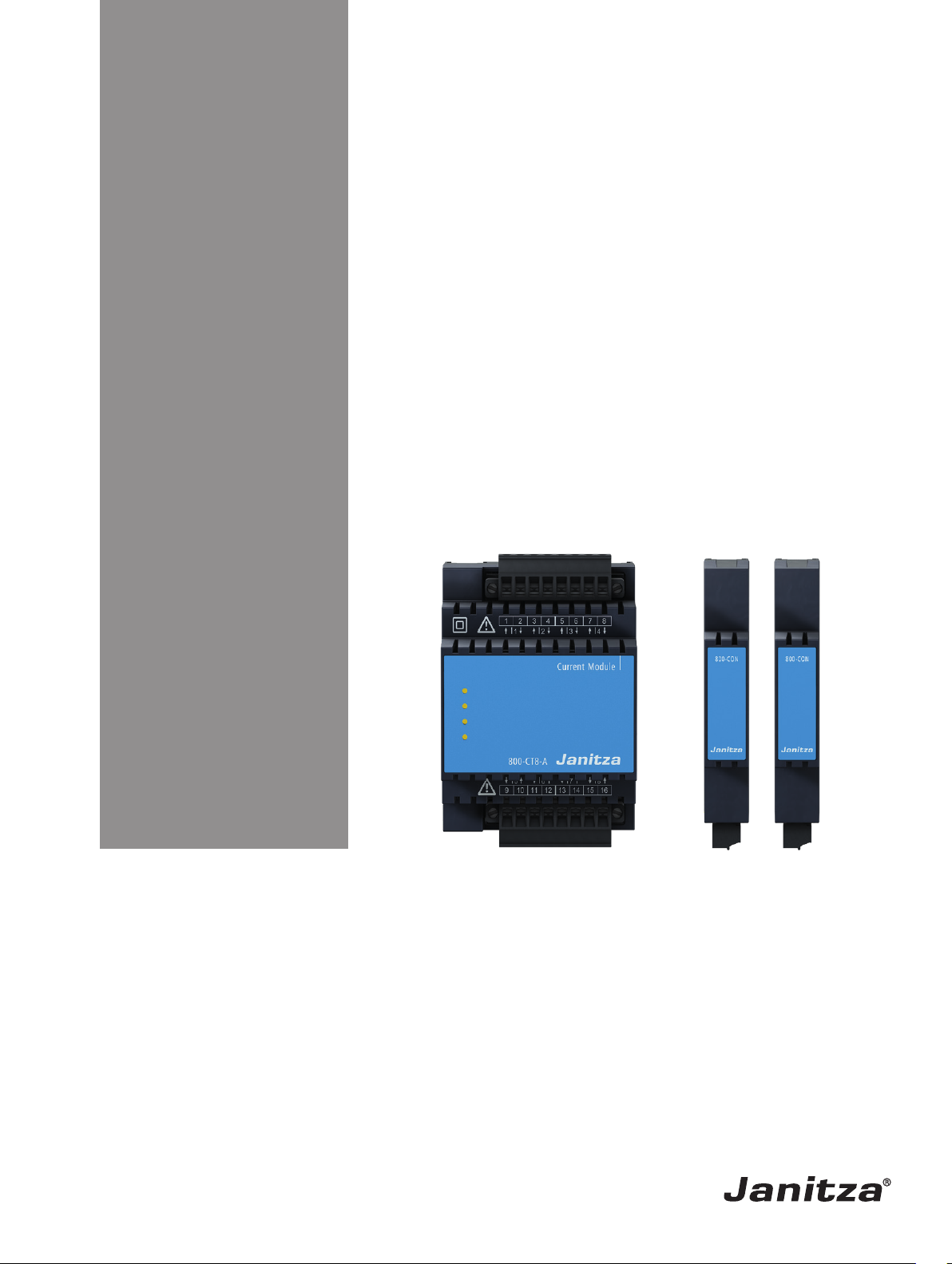
800-CT8-A current measuring module
800-CON transfer modules
Extension modules for the UMG 801
User manual and technical data
www.janitza.de
Janitza electronics GmbH
Vor dem Polstück 6
D-35633 Lahnau
Doc. no.: 2.053.023.0a Date: 11/2019
Support tel. +49 6441 9642-22
Fax +49 6441 9642-30
Email: info@janitza.de
www.janitza.de
Page 2
Modules 800-CT8-A | 800-CON www.janitza.de
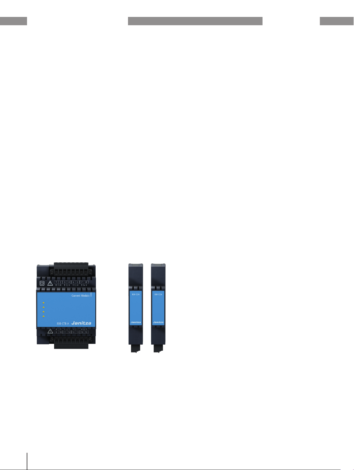
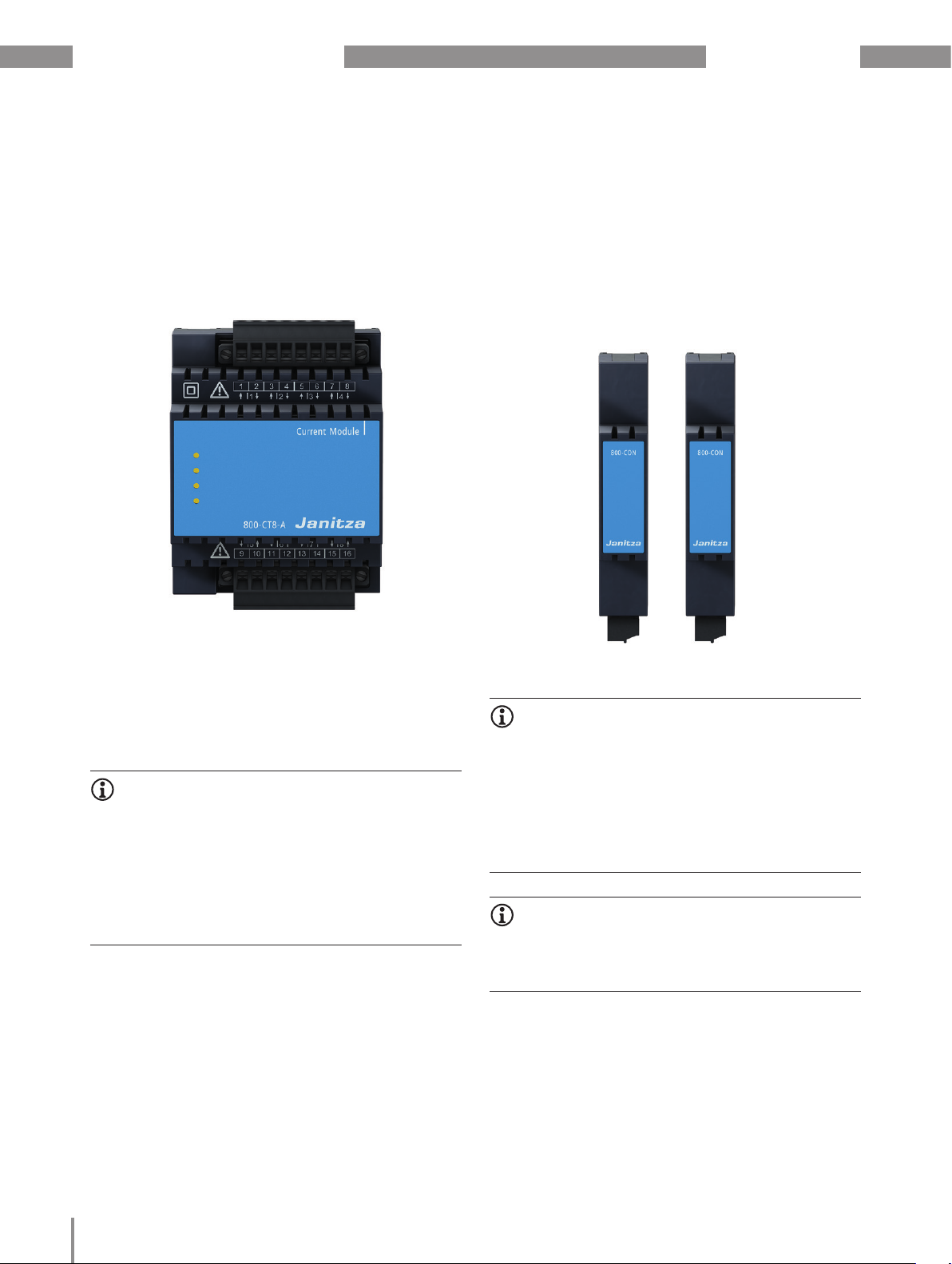
800-CT8-A
current measuring module
800-CON
transfer modules (set of 2)
Modules for UMG 801
Doc. no.: 2.053.023.0a
Date: 11/2019
The German version is the original edition of the documentation
2
Page 3

www.janitza.de
Modules 800-CT8-A | 800-CON
Subject to technical changes.
The contents of our documentation have been compiled with great care and reflect the current state of the
information available to us. Nonetheless, we wish to point out that updates of this document are not always
possible at the same time as technical refinements are implemented in our products. Please see our website
under www.janitza.de for the current version.
Please see our website under www.janitza.de for the current version.
3
Page 4

Modules 800-CT8-A | 800-CON www.janitza.de
TABLE OF CONTENTS
1. Information on the devices and the user manual 8
1. 1 Disclaimer 8
1. 2 Copyright notice 8
1. 3 Technical changes 8
1. 4 About this user manual 8
1. 5 Defective device/disposal 9
2. Safety 10
2. 1 Display of warning notices and safety information 10
2. 2 Hazard levels 10
2. 3 Product safety 11
2. 4 Hazards when handling the device, components and modules 11
2. 5 Electrically qualified personnel 12
2. 6 Warranty in the event of damage 12
2. 7 Safety information for handling current transformers 12
3. Product description 14
3. 1 800-CT8-A module 14
3. 2 800-CON module (set of 2) 14
3. 3 Incoming goods inspection 15
3. 4 Intended use 15
3. 5 Overview of module functions 15
3. 6 EU conformity declaration 15
3. 7 Scope of delivery, 800-CT8-A current measuring module. 16
3. 8 Scope of delivery, 800-CON transfer module (set of 2) 16
3. 9 Accessories for “800-CON transfer module” 16
3. 10 Operating concept 17
3. 11 GridVis® network analysis software 17
4
Page 5

www.janitza.de
4. Mounting 18
4. 1 Mounting the 800-CT8-A module 18
4. 2 Mounting the 800-CON module 21
4. 3 Connection of device and module series with the 800-CON transfer modules 22
4. 4 Connections/controls on 800-CT8-A module 24
4. 5 Marking of the 800-CT8-A module - rating plate 25
4. 6 Connections/controls on 800-CON module 26
4. 7 Marking of the 800-CON module - rating plate 27
5. Installation 28
5. 1 Current measurement with module 800-CT8-A 28
5. 2 Example schematic diagram “Connection variants for current measurement” 29
5. 3 Data transfer with 800-CON module 30
Modules 800-CT8-A | 800-CON
5. 4 Data cable for connecting the 800-CON transfer modules 31
6. PC connection 32
6. 1 PC connection of the current measuring modules via the basic device (UMG 801) 32
6. 2 PC connection of the basic device (UMG 801) with current measuring module
or your module series via the Ethernet interface 32
7. Operation and button functions of the basic device with module 34
7. 1 Operation and button functions of the basic device with 800-CT8-CON module 34
7. 2 Module-relevant menu items of the basic device with one module 34
8. Module-relevant configurations 36
8. 1 800-CT8-A module - Current transformer configuration on the basic device 36
8. 2 800-CT8-A module - Current transformer configuration in the GridVis® software 37
9. Module-relevant measuring displays 38
9. 1 800-CT8-A module - Measuring displays 38
10. Device views - 800-CT8-A current measuring module 46
5
Page 6

Modules 800-CT8-A | 800-CON www.janitza.de
11. Technical data - 800-CT8-A current measuring module 47
11. 1 Functional performance characteristics of 800-CT8-A current measuring module
(Only valid in conjunction with UMG 801!) 49
12. Device views - 800-CON transfer module 50
13. Technical data - 800-CON transfer module 51
14. Dismounting 52
14. 1 Dismounting the 800-CT8-A module 52
14. 2 Exchanging an 800-CT8-A module 53
14. 3 Dismounting the 800-CON module 54
15. Service and maintenance 56
15. 1 Repair 56
15. 2 Service 56
15. 3 Device adjustment 56
15. 4 Calibration interval 56
15. 5 Firmware update 56
15. 6 Procedure in the event of a malfunction 56
15. 7 Resetting the module to the standard factory settings 56
15. 8 Information on saving measured values and configuration data 57
6
Page 7

www.janitza.de
Modules 800-CT8-A | 800-CON
7
Page 8

Modules 800-CT8-A | 800-CON www.janitza.de
1. Information on the devices and the user manual
1.1 Disclaimer
Compliance with the usage information for the
devices (modules/components) is a prerequisite for
safe operation and attaining the stated performance
characteristics and product features.
Janitza electronics GmbH assumes no liability for
bodily injury, material damage or financial losses
which result from disregard of the usage information.
Ensure that the usage information for the products is
legible and accessible.
1.2 Copyright notice
© 2019 - Janitza electronics GmbH - Lahnau. All
rights reserved.
Any reproduction, processing, distribution or other
use of this usage information, in whole or in part, is
prohibited.
All trademarks and the rights arising from them are
the property of the respective owners of these rights.
1.4 About this user manual
If you have questions, suggestions or ideas for
improvement of the user manual, please let us know
via email at: info@janitza.de.
INFORMATION
This user manual describes the modules for the
UMG 801 and provides information on the operation of
the devices.
Also consult the additional usage information relevant
for this user manual, such as:
· Installation instructions.
· Data sheets.
· The "Safety information" supplement.
· The supplement on mounting the modules.
· Usage information on the basic device.
Moreover, the GridVis® software has an “online help”
feature.
1.3 Technical changes
· Make sure that your device (modules/components)
matches the user manual.
· This user manual applies to the modules for the
UMG 801. Separate validities and distinctions are
marked.
· First make sure you have read and understood the
usage information accompanying the product.
· Keep the usage information associated with the
product available for the entire service life and pass
it on to any possible subsequent users.
· Find out about device revisions and the associated
modifications of the usage information associated
with your product at www.janitza.de.
8
Page 9

www.janitza.de
1.5 Defective device/disposal
Before sending defective devices, modules or
components back to the manufacturer for testing:
· Contact the manufacturer's Support department.
· Send devices, modules or components complete
with all accessories.
· When doing so, please bear the terms for
transportation in mind.
INFORMATION
Please return defective or damaged devices, modules
or components to Janitza electronics GmbH in
accordance with the shipping instructions for air or
road freight (complete with accessories).
Observe special regulations for devices with built-in
batteries or rechargeable batteries!
Do not attempt to open or repair the device (the
module, the component) on your own because
otherwise all warranty claims become invalid!
Modules 800-CT8-A | 800-CON
For the disposal of the device (the module, the
component), please observe national regulations!
Dispose of individual parts, as applicable, depending
on their composition and existing country-specific
regulations, e.g. as
· Electronic waste
· Batteries and rechargeable batteries
· Plastics
· Metals
Engage a certified disposal company to handle
scrapping as needed.
Information on “Service and maintenance” of your
device can be found in chapter 15 on page 56.
9
Page 10
Modules 800-CT8-A | 800-CON www.janitza.de
2. Safety
The chapter on Safety contains information which
must be observed to ensure your personal safety
and avoid material damage.
2.1 Display of warning notices and safety
information
The warning notices shown below
· are found throughout the usage information.
· can be found on the devices themselves.
· indicate potential risks and hazards,
· underscore aspects of the information provided that
clarifies or simplifies procedures.
This additional symbol on the device (module/
component) itself indicates an electrical hazard that
can lead to severe injury or death.
This general warning symbol draws attention to a
possible risk of injury. Be certain to observe all of the
information listed under this symbol in order to avoid
possible injury or even death.
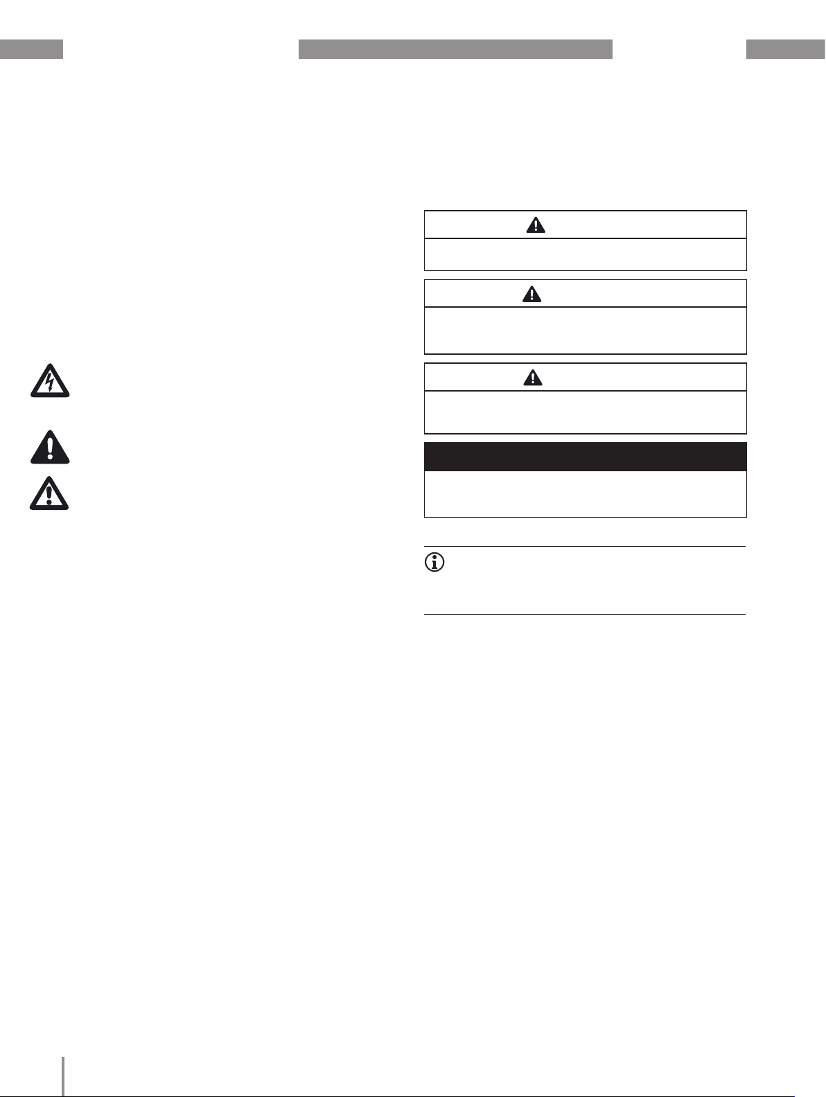
2.2 Hazard levels
Warning and safety information is marked by a
warning symbol, and the hazard levels are shown as
follows, depending on the degree of hazard:
DANGER
Warns of an imminent danger which, if not avoided,
results in serious or fatal injury.
WARNING
Warns of a potentially hazardous situation which, if
not avoided, could result in serious injury or death.
CAUTION
Warns of an immediately hazardous situation which,
if not avoided, can result in minor or moderate injury.
ATTENTION
Warns of an immediately hazardous situation which,
if not avoided, can result in material or environmental
damage.
INFORMATION
Indicates procedures in which there is no hazard of
personal injury or material damage.
10
Page 11

www.janitza.de
2.3 Product safety
The devices, components and modules reflect
current engineering practice and accepted safety
standards, but hazards can arise nonetheless.
Observe the safety regulations and warning notices.
If notices are disregarded, this can lead to personal
injury and/or damage to the product.
Every type of tampering with or use of the devices
and the modules,
· which goes beyond the mechanical, electrical or
other operating limits can lead to personal injury
and/or damage to the product;
· constitutes "misuse" and/or "negligence" under the
product’s warranty and thus voids the warranty for
any possible resulting damage.
Read and understand the user manual and the usage
information on the basic device before installing,
operating, maintaining and using the devices,
components and modules.
Only operate the devices, components and modules
when they are in perfect condition and in compliance
with this user manual and the usage information that
is included. Send defective devices, components
or modules back to the manufacturer in compliance
with proper transport conditions.
Retain the user manual throughout the service life of
your product and keep it at hand for consultation.
When using the device, component or module, also
observe the legal and safety regulations for your
system that are applicable for the respective use
case.
2.4 Hazards when handling the device,
components and modules
When operating electric devices, components
or modules, it is unavoidable for certain parts
of these devices to conduct hazardous voltage.
Consequently, severe bodily injury or material
damage can occur if they are not handled properly.
Therefore, when handling our devices, components,
or modules, always observe the following:
· do not exceed the limit values specified in the user
manual and on the rating plate! This must also be
observed during testing and commissioning!
· Take note of the safety and warning notices in
all usage information that belongs to the device,
components or modules!
Modules 800-CT8-A | 800-CON
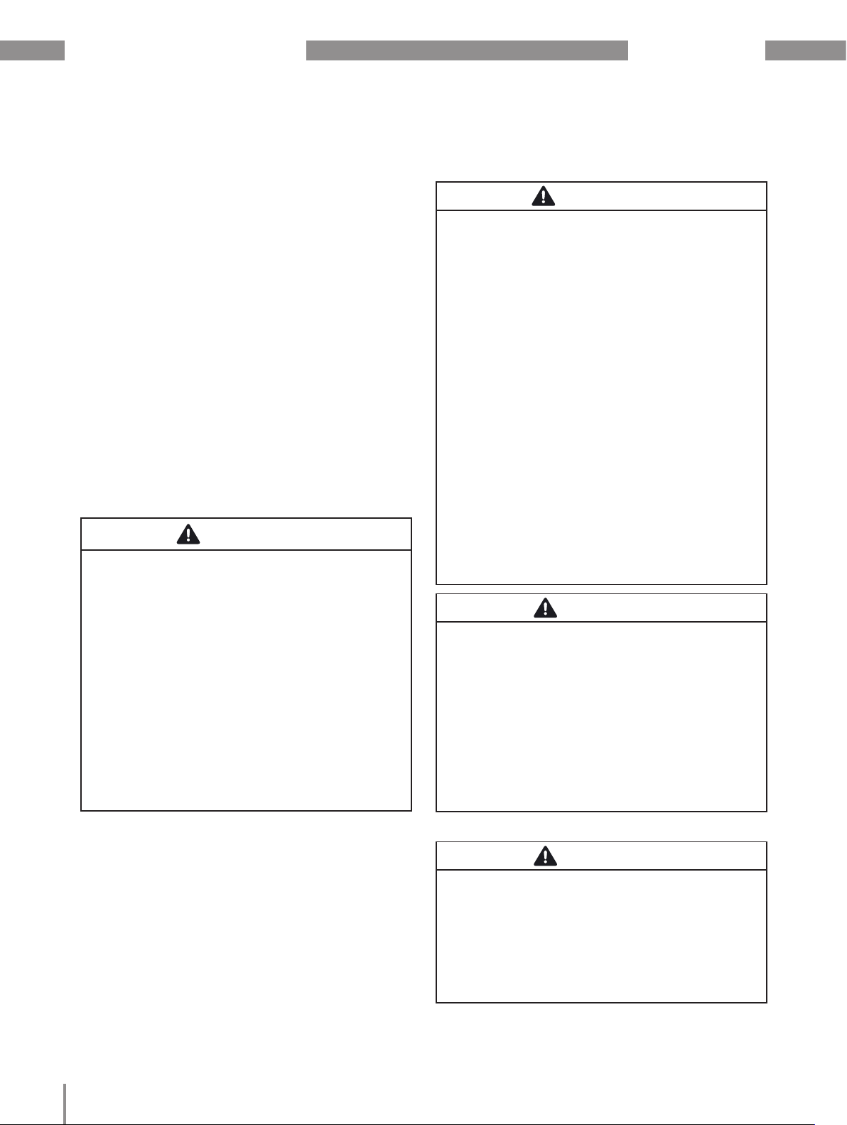
WARNING
Risk of injury due to electrical current and voltage!
Severe bodily injury or death can result! Therefore
please abide by the following:
· Do not touch bare, stripped wires or device
inputs that are dangerous to touch on the
devices, components and modules.
· Switch off your installation before commencing
work! Secure it against being switched on!
Check to be sure it is de-energized! Ground and
short circuit! Cover or block off adjacent live
parts!
· During operation and troubleshooting
(especially with DIN rail devices), check the
environment for dangerous voltages and switch
these off if necessary!
· Wear protective clothing and protective
equipment in accordance with applicable
guidelines when working on electrical systems!
· Before making connections, ground the device
/ component / module by means of the ground
wire connection, if present!
· Do not touching bare or stripped leads that are
energized! Equip stranded conductors with wire
ferrules!
· Hazardous voltages can be present in all
circuitry parts that are connected to the power
supply.
· Protect wires, cables and devices with a
suitable line circuit breaker/fuse!
· Never switch off, remove or tamper with safety
devices!
· There can still be hazardous voltages present in
the device or in the component (module) even
after it has been disconnected from the supply
voltage (capacitor storage).
· Do not operate equipment with current
transformer circuits when open.
· Only connect screw terminals with the same
number of poles and design!
· Do not exceed the limit values specified in
the user manual and on the rating plate! This
must also be observed during testing and
commissioning.
· Take note of the safety and warning notices
in the usage information that belongs to the
device, components or modules!
11
Page 12
Modules 800-CT8-A | 800-CON www.janitza.de
2.5 Electrically qualified personnel
To avoid bodily injury and material damage, only
electrically qualified personnel are permitted to work
on the devices and their components, modules,
assemblies, systems and current circuits who have
knowledge of:
· the national and international accident prevention
regulations,
· safety technology standards,
· installation, commissioning, operation,
disconnection, grounding and marking of electrical
equipment,
· the requirements concerning personal protective
equipment.
Electrically qualified persons within the scope of the
technical safety information of all usage information
associated with the device and its components
(modules) are persons who can furnish proof of
qualification as an electrically skilled person.
WARNING
Warning against unauthorized manipulation or
improper use of the device or its components
(modules)!
Opening, dismantling or unauthorized manipulation of
the device and its components (modules) which goes
beyond the mechanical, electrical or other operating
limits indicated can lead to material damage or injury,
up to and including death.
· Only electrically qualified personnel are
permitted to work on the devices and their
components (modules), assemblies, systems
and current circuits.
· Always use your device or component (module)
only in the manner described in the associated
documentation.
· If there is discernible damage, send the
device or the component (module) back to the
manufacturer!
2.7 Safety information for handling current
transformers
WARNING
Risk of injury due to large currents and high
electrical voltage on the current transformers!
Current transformers operated while open on the
secondary side (high voltage peaks pose a hazard
when touched) can result in severe bodily injury or
death.
· Avoid operating the current transformers while
open; short circuit the unloaded transformers!
· Before interrupting the current supply, short
circuit the secondary connections of the
current transformers. Switch any test switches
that automatically short circuit the secondary
lines of the current transformers to the “Test”
status (Check the test switch/short circuiting
connection beforehand)!
· Only use current transformers with basic
insulation to IEC 61010-1:2010!
· Caution, even current transformers rated as
safe for open operation can pose a hazard
when touched during operation while open!
· Make sure that screw terminals for the current
transformer connection on the device are
adequately tightened!
· Comply with the information and provisions
in the documentation of your current
transformers!
CAUTION
Risk of injury or damage to the meter due to high
measurement currents at the connections of the
current transformers!
High measurement currents can cause temperatures
of up to 80 °C (176 °F) on the connections of the
current transformers
· Use wiring that is designed for an operating
temperature of at least 80 °C (176 °F)!
· The current transformers can be hot even after
the power supply has been switched off. Allow
the connections of the current transformers
and the connecting cables to cool down before
touching them!
2.6 Warranty in the event of damage
Any unauthorized tampering with or use of the
device, component or module constitutes "misuse"
and/or "negligence" under the product’s warranty
and thus voids the warranty for any possible
resulting damage. In this regard, please take note of
chap. „3.4 Intended use“ on page 15.
12
CAUTION
Risk of injury or damage to the basic device
(module) and/or your system due to a short circuit!
Inadequate insulation at the current measurement
inputs of the modules with respect to the supply
circuits of the basic device can cause dangerous
voltages at the measuring input or damage to your
device (module)/system.
· Ensure reinforced or double insulation with
respect to the supply circuits!
Page 13

www.janitza.de
Modules 800-CT8-A | 800-CON
13
Page 14
Modules 800-CT8-A | 800-CON www.janitza.de
3. Product description
3.1 800-CT8-A module
The current measuring module
· extends the functional range of the basic device
to include additional current measuring channels
(2 groups of 4 current measuring channels each);
· is suitable for current transformers with transformer
ratios of ../1 A or ../5 A.
3.2 800-CON module (set of 2)
The module set, consisting of 2 transfer modules,
is used to connect remote measurement points.
With the transfer modules, you can implement
meter and module topologies (e.g. UMG 801 with
modules 800-CT8-A) with flexible arrangement of
your DIN rails (for types, see Technical Data) in the
switchboard cabinet or small distribution board.
Fig.: 800-CT8-A module
The basic device (UMG 801) with current measuring
module measures current exclusively via current
transformers. The current transformers require a
basic insulation according to IEC 61010-1:2010 for
the nominal voltage of the circuit.
INFORMATION
When setting up your meter and module topology,
note that:
· The UMG 801 as the basic device allows the
mounting of up to 10 modules.
· The scope of delivery for the module includes the
appropriate bus connector (JanBus interface) for
connection to the basic device.
· The maximum bus length of the JanBus is 100 m.
Fig.: 800-CON module (transfer module,
output / input)
INFORMATION
· Both modules in the set of 2 are suitable as input
or output modules!
· The scope of delivery for the transfer modules
includes the appropriate bus connector (JanBus
interface).
· When setting up your meter and module topology,
make sure that the maximum bus length of the
JanBus is 100 m.
INFORMATION
Please also observe all usage information
associated with the basic device in addition to the
usage information for the modules!
14
Page 15

www.janitza.de
Modules 800-CT8-A | 800-CON
3.3 Incoming goods inspection
The prerequisites for trouble-free and safe operation
of the modules include proper transport, storage,
setup and assembly, as well as proper operation
and maintenance.
Exercise due caution when unpacking and packing
the device, do not use force and only use suitable
tools. Check:
· The modules by performing a visual inspection to
ensure flawless mechanical condition.
· The scope of delivery (see chap. 3.7 and 3.8) with
respect to completeness before beginning with
assembly and installation.
If it must be assumed that safe operation of your
basic device with module is not possible:
1. Switch off the power to your system (your
device)!
2. Secure it against being switched back on!
3. Check to be sure it is de-energized!
4. Ground and short circuit the system (device)!
5. Cover or block off adjacent live parts!
Safe operation is impossible, if, for example, the
basic device with module:
· has visible damage,
· no longer functions despite an intact power supply,
· was subjected to extended periods of unfavorable
conditions (e.g. storage outside of the permissible
climate thresholds without adjustment to the room
climate, condensation, etc.) or transport stress
(e.g. falling from an elevated position, even without
visible external damage, etc.).
3.4 Intended use
The modules/components
· Are intended as expansion or transfer modules for
the basic device UMG 801 in switch cabinets and
small distribution boards.
· Must only be mounted with basic devices that are
disconnected from the power supply (see chap. „4.
Mounting“ on page 18).
INFORMATION
Please note:
More information on certain functions of the basic
device with modules can be found in the usage
information for the basic device.
The basic device and the modules (800-CT8-A and
800-CON) are not designed for installation:
· In vehicles! Use of the basic device with modules
in non-stationary equipment is considered an
exceptional environmental condition and is only
permissible by special agreement.
· In environments with harmful oils, acids, gases,
vapors, dusts, radiation, etc.
· In potentially explosive environments.
3.5 Overview of module functions
800-CT8-A module:
· 8 current measurement inputs (2 groups of 4)
· Measuring category 300 V CAT II
· Nominal current 1 A/5 A configurable
ATTENTION
Improper handling may cause damage to the
module and result in material damage!
The contacts of the bus connectors (Janbus interface)
can bend or break off and destroy the bus connector.
· Never touch or manipulate the contacts of the bus
connector!
· Never force the bus connector into the module!
Please refer to the chapter on this „4. Mounting“
on page 18.
· When handling, transporting and storing
the module, protect the contacts of the bus
connector!
800-CON module:
· JanBus interface (proprietary) via bus connector
and twisted pair, shielded data cable (1:1
connection via shield clamps) to device and module
series (see section „5.4 Data cable for connecting
the 800-CON transfer modules“ on page 31).
3.6 EU conformity declaration
Please see the EU declaration of conformity posted
at www.janitza.de for the laws, standards and
directives applied by Janitza electronics GmbH for
the devices.
15
Page 16
Modules 800-CT8-A | 800-CON www.janitza.de
3.7 Scope of delivery, 800-CT8-A current
measuring module.
Quan-
tity
Tab. Scope of delivery, 800-CT8-A current measuring module
Part. no. Designation
1 52.31.201
1 52.31.207
1 10.01.953 End bracket
1 33.03.378
1 33.03.342
1 33.03.059 “Mounting” supplement
1 10.01.853
Module 800-CT8-A
(current measuring module)
Bus connector - Current measuring
module
Installation instructions (DE/EN)
"Current measuring module for the
UMG 801"
"Safety information” supplement
(12 languages)
Screw terminal, plug-in, 8-pole
(current measurement I1..I4 and
I5..I8)
3.8 Scope of delivery, 800-CON transfer
module (set of 2).
Quan-
tity
Tab. Scope of delivery, 800-CON transfer module
Part. no. Designation
1 52.31.210
1 52.31.208 Bus connector - Transfer on right
1 52.31.209 Bus connector - Transfer on left
2 10.02.188 Shield clamps
2 10.01.953 End bracket (Weidmüller)
1 33.03.379
1 33.03.342
1 33.03.059 “Mounting” supplement
2 10.01.938 Screw terminal, plug-in, 8-pole
800-CON module - Transfer module
(set of 2)
Installation instructions (DE/EN)
"Transfer modules for the UMG 801"
"Safety information” supplement
(12 languages)
3.9 Accessories “800-CON transfer module”
Quan-
Tab. Accessories
Part. no. Designation
tity
1 08.02.451
1 08.02.452
Data cable for connecting the
"transfer modules" (1000 mm pre-assembled, twisted pair data
cable)
Data cable for connecting the
"transfer modules" (225 mm pre-assembled, twisted pair stranded hook-up wires)
INFORMATION
· The modules are delivered with the necessary
screw terminals and bus connectors (JanBus
interface) for connection to the basic device or
other modules.
· All supplied options and design variants are
described on the delivery note.
· With the GridVis® network analysis software
available at www.janitza.de, you can configure
your basic device with modules and read out data
for analysis (prerequisite: PC connection with your
basic device).
16
Page 17

www.janitza.de
Modules 800-CT8-A | 800-CON
3.10 Operating concept
Options to configure the basic device with current
measuring module or to read measured values:
· Display and buttons on the basic device (user
interface).
· GridVis® network analysis software.
· RS-485 interface or Ethernet interface.
INFORMATION
Please take note of the documentation of your
basic device (without the module)! Basic or
identical information and chapters, such as
· Commissioning
· Configuration
· Technical data
· Error messages
· Procedure in the event of a malfunction, etc.
can be found in the usage information of your
basic device.
A list of parameters and Modbus addresses with
data on your basic device with module is available
for you as a download at www.janitza.de.
3.11 GridVis® network analysis software
With the GridVis® software, you have the perfect
tool for programming, reading out and visualizing
measurement data (download at www.janitza.de).
Performance characteristics of the GridVis®
software
· Configuration of the device
· Graphic display of measured values
· Online help and tutorials
Connections to the PC (GridVis® software)
Connections for communication between the PC
and the basic device with modules can be found in
chapter 6 on page 32.
INFORMATION
This user manual describes the modules and
provides information on the operation of the
modules via the basic device (UMG 801).
The GridVis® software has an online help with
tutorials.
17
Page 18
Modules 800-CT8-A | 800-CON www.janitza.de
4. Mounting
CAUTION
Disregard of the assembly instructions may cause
property damage or personal injury!
Disregard of the assembly instructions may cause
damage to your basic device with module or destroy
it and/or may also result in personal injury.
· In addition to the installation instructions for
your module, also observe the installation
instructions for your basic device, in particular
the safety and warning information.
· Before installing modules
- Disconnect the supply of power to the system!
- Secure it against being switched on!
- Check to be sure it is de-energized!
- Ground and short circuit!
- Cover or block off adjacent live parts!
· Provide adequate air circulation in your installa-
tion environment and cooling, as needed, when
the ambient temperatures are high.
· Return defective modules to Janitza electronics
GmbH in accordance with the shipping instructions for air or road freight (complete with
accessories).
· All usage information is also available as a
download at www.janitza.de.
2. If this has not yet been done, plug the bus
connector (JanBus interface) included in delivery
into the sockets on the rear of your module.
ATTENTION
Improper handling may cause damage to the
module and result in material damage!
The contacts of the bus connectors (Janbus interface)
can bend or break off and destroy the bus connector.
· Never touch or manipulate the contacts of the
bus connector!
· Never force the bus connector into the module!
· When handling, transporting and storing the
module, protect the contacts of the bus connector!
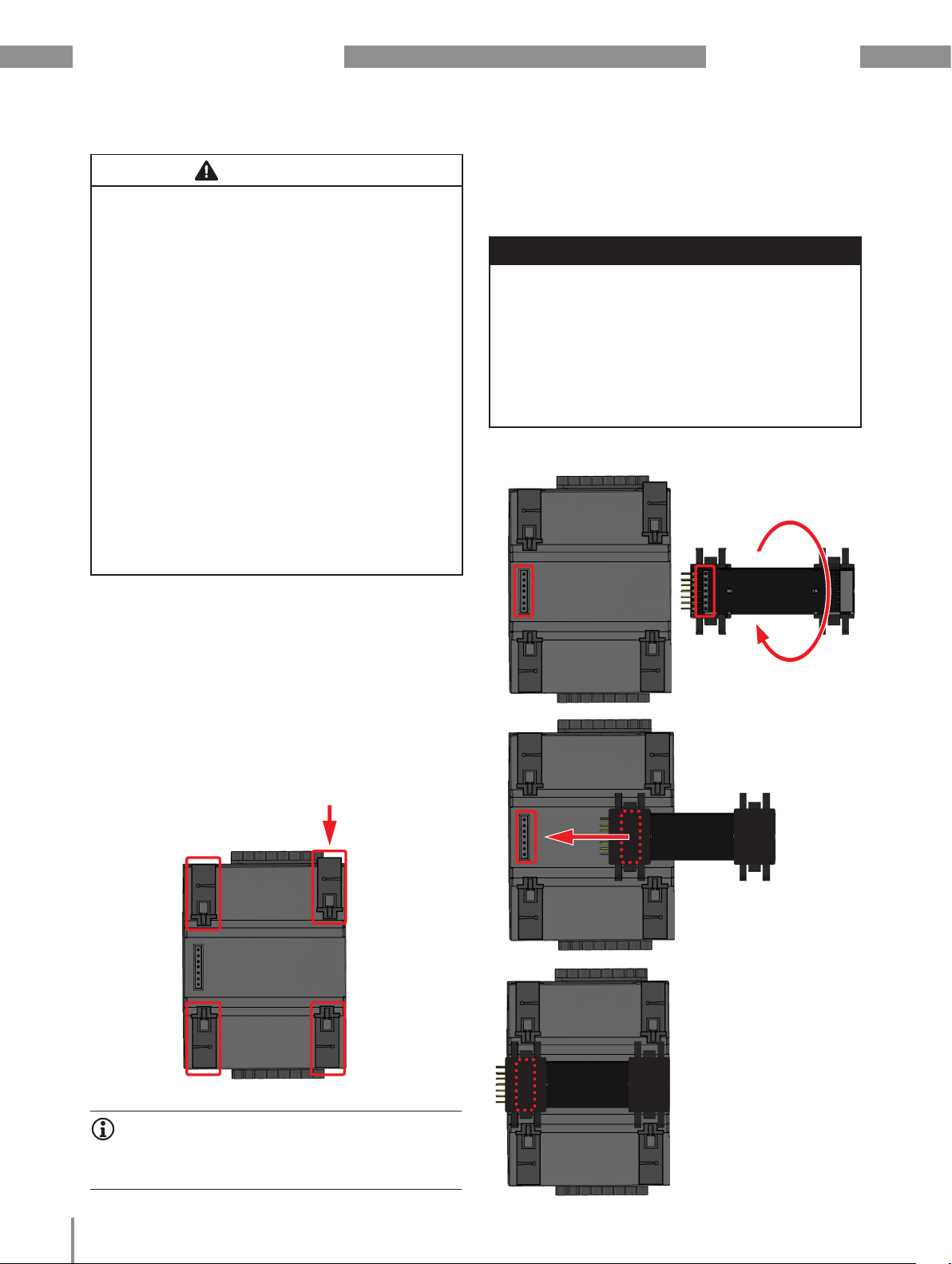
4.1 Mounting the 800-CT8-A module
Observe the mounting instructions for your basic
device (e.g. check bus connector installation!) and
mount the 800-CT8-A module in the de-energized
system as follows:
1. Press in the bottom bolts on the rear of the
module.
Bottom bolts
Fig.: Module rear view
INFORMATION
press
Bus connector
Bus connector
Twisted
Press the bus connector
contacts into the module
sockets
The following module assembly sequence must be
observed!
18
Fig.: Module rear view.
Page 19

www.janitza.de
Modules 800-CT8-A | 800-CON
3. Press your module with the bus connector
onto the DIN rail (for suitable DIN rail types see
chapter „11. Technical data - 800-CT8-A current
measuring module“ on page 47) until the 4
bottom bolts snap into place.
800-CT8-A module
With bus connector
UMG 801
Bottom bolts
click!
DIN rail
Fig.: Side view, UMG 801 and 800-CT8-A module
INFORMATION
4. Push the contacts of your module bus connector
into the sockets of the basic device bus
connector (or into the sockets of the attached
module) so that the bus connectors (devices) are
coupled.
UMG 801
Fig.: Side view, UMG 801 and 800-CT8-A module
800-CT8-A module
Internal bus connector
5. Then cable your module and apply voltage to the
basic device (system).
INFORMATION
The basic device automatically recognizes the
module during the power-up procedure!
Before coupling the module, check to be certain
your basic device is de-energized! Coupling
while energized can destroy your basic device or
module!
19
Page 20

Modules 800-CT8-A | 800-CON www.janitza.de
Bottom bolts
End bracket
DIN rail
Fig. Assembly example:
Front view UMG 801 (basic device) with 800-CT8-A module
INFORMATION
After installing your module, check the function of
the communication between the basic device and
the module using the display on the basic device
as follows:
· When you are in the Home measuring display
of the basic device, pressing the button 1 ESC
takes you to the Menu window.
· Use buttons 2 (5) and 5 (6) to select the menu
item System information and confirm with button 3
Enter.
· The System information window with the items
Basic device and Module 1 appears.
System information
Main device
Module 1
Bus connector
contacts
JanBus
JanBus
interface
Bus connector
sockets
Bottom bolts
interface
for further
modules
Bus connector
sockets
Error after starting the basic device with module:
INFORMATION
The basic device does not recognize modules
during the power-up procedure!
If there is no communication to modules, the
module functions are not supported (e.g. current
measurements).
· Disconnect your system from the power supply
and check the condition of the bus connectors
and the connections of your modules to the
basic device (JanBus interface). If necessary,
push the contacts of the module bus
connectors into the sockets of the basic device
bus connector or the attached modules so that
the bus connectors (devices) are coupled.
· For remote module series, check the
connection of the transfer modules with the
connection via the shield clamps.
· If necessary, restart the basic device.
· If these measures do not lead to the desired
result, please contact our Support –
www.janitza.de
ESC
Fig.: System information window with the
entries of the basic device and module 1.
· The basic device has detected module 1.
Observe the following:
· The basic device allows the mounting of up to 10
modules!
· The maximum bus length of the JanBus is 100 m.
· Always start and end your device and module series
with end brackets (cf. Fig. "Example of a meter and
module topology” on page 30).
20
INFORMATION
The figure above shows an example of mounting the
800-CT8-A module. Use end brackets to set up your
device and module series on the DIN rails.
Page 21

www.janitza.de
Modules 800-CT8-A | 800-CON
4.2 Mounting the 800-CON module
Observe the mounting instructions of your basic
device (e.g. check bus connector installation!) and
mount the 800-CON module (transfer module) in the
de-energized system as follows:
1. Press in the bottom bolts on the rear of the
module.
Fig.: Module rear view
2. If this has not yet been done, plug the bus
connector (JanBus interface) included in delivery
into the sockets on the rear of your module.
Bus connector
INFORMATION
· The following module assembly sequence must
be observed!
· Always mount components of your JanBus system from the output bus connector to the input
bus connector. This will avoid an incorrect connection of remote JanBus systems! Cf. chapter
„5.3 Data transfer with 800-CON module“ on
page 30.
ATTENTION
Improper handling may cause damage to the
module and result in material damage!
The contacts of the bus connectors (Janbus interface)
can bend or break off and destroy the bus connector.
· Never touch or manipulate the contacts of the
bus connector!
· Never force the bus connector into the module!
· When handling, transporting and storing
the module, protect the contacts of the bus
connector!
Bus connector
rotated
Press the bus connector
contacts into the module
press
sockets
Fig.: Module rear view.
21
Page 22

Modules 800-CT8-A | 800-CON www.janitza.de
3. Press your module with the bus connector
onto the DIN rail (for suitable DIN rail types see
chapter „13. Technical data - 800-CON transfer
module“ on page 51) until the 2 bottom bolts
snap into place.
800-CON module
with bus connector
UMG 801
Fig.: Side view, UMG 801, 800-CT8-A and 800-CON module
800-CT8-A module
click!
DIN rail
4. Push the contacts of your module bus connector
into the sockets of the connected module
(or basic device) so that the bus connectors
(devices) are coupled.
5. End your device and module series with end
brackets (see Fig. Example "Devices and module
series" in chapter 4.3 on page 22).
UMG 801
800-CT8-A module
800-CON
module
4.3 Connection of device and module series
with the 800-CON transfer modules
To ensure trouble-free operation of your device
series with modules and thus your system, connect
your transfer modules via shield clamps. The
shield connection serves as protection against
overvoltages and electromagnetic interference.
Also provide a strain relief during installation
that protects the data cable from being torn out
unintentionally. Connect the transfer modules with
the recommended data cables. Please note the
warnings and information below!
ATTENTION
Incorrect installation of the data cable can destroy
your basic device with modules or your system!
A faulty or incorrectly installed data cable between
the transfer modules can lead to the destruction of
your basic device with modules and thus to material
damage.
· For the connection between the transfer
modules, use a twisted pair, stranded, shielded
data cable with a 1:1 cable connection (cf. Chap
„5.4 Data cable for connecting the 800-CON
transfer modules“ on page 31)!
· Always connect your transfer modules via
shield clamps with a strain relief!
· Protect your system against overvoltages and
electromagnetic interference by connecting the
data cable shield to the shield clamp!
· Always connect the data cable shield (ground)
within the same grounding potentials! With
different ground potentials, connect the data
cable shield at least at one end!
DIN rail
Internal bus connector
Fig.: Side view, UMG 801, 800-CT8-A and 800-CON module
6. Then cable your module and apply voltage to
the basic device (system). The basic device
recognizes the plugged in module automatically.
22
ATTENTION
Improper handling may cause damage to the
module and result in material damage!
The contacts of the bus connector (Janbus interface)
can bend or break off and destroy the bus connector!
· Never touch or manipulate the contacts of the
bus connector.
· Never force the transfer module with bus
connector contacts into the bus connector
sockets!
· When handling, transporting and storing the
transfer module, protect the contacts of the
bus connector!
Page 23

www.janitza.de
Modules 800-CT8-A | 800-CON
800-CT8-A
module
Fig. Example "Device and
module series": Wiring of the
transfer module (output)
800-CON transfer
module
Shield clamp
End bracket
Heat-shrink tubing
INFORMATION
The basic device does not recognize modules
during the power-up procedure!
If there is no communication to modules, the
module functions are not supported (e.g. current
measurements).
· Disconnect your system from the power supply
and check the condition of the bus connectors
and the connections of your modules to the
basic device (JanBus interface). If necessary,
push the contacts of the module bus
connectors into the sockets of the basic device
bus connector or the attached modules so that
the bus connectors (devices) are coupled.
· For remote module series, check the
connection of the transfer modules with the
connection via the shield clamps.
· If necessary, restart the basic device.
· If these measures do not lead to the desired
result, please contact our Support –
www.janitza.de
Shielded
data cable
Strain relief
DIN rail
800-CON transfer
module
Fig. Example “Remote
module series": Wiring of the
transfer module (input)
800-CT8-A
module
Observe the recommended data cables for the
connection between the transfer modules (see
chap. „5.4 Data cable for connecting the 800-CON
transfer modules“ on page 31)!
23
Page 24

Modules 800-CT8-A | 800-CON www.janitza.de
4.4 Connections/controls on 800-CT8-A module
5
4
2
3
1
6
7 7
7 7
INFORMATION
The current measuring module is supplied with the
necessary screw terminals and bus connectors
(JanBus interface) for connection to the basic device
or other modules.
Item Designation Description
4 current measurement inputs in the
1
group, terminals 9/10, 11/12, 13/14,
15/16
2 LED
3 LED
4 2 LEDs Blink “orange" during operation and indicate cyclic data exchange.
4 current measurement inputs in the
5
group, terminals 1/2, 3/4, 5/6, 7/8
6 JanBus interface Connection sockets for the bus connector
7 Bottom bolt For mounting the module on the DIN rail
8 JanBus interface Bus connector insertion into the module
Current measurements I5, I6, I7, I8
Lights "green" if the supply of power via the JanBus interface of the basic
device is correct; the device is ready for operation.
Lights up "red" at power-up and remains so until completion of
initialization (module not yet initialized). Then there is a switchover to cyclic
data exchange (pos. 4).
Current measurements I1, I2, I3, I4
9
8
10
9 Bus connector contacts (JanBus) Connection to the basic device (or connected modules)
10 Bus connector sockets (JanBus) Connection of additional modules
24
Page 25

www.janitza.de
4.5 Marking of the 800-CT8-A module - Rating plate
4 5 6
Modules 800-CT8-A | 800-CON
3
2
1
Item Designation Description
1 Part number Current measurements I5, I6, I7, I8
Symbol for “Danger sign”
2
3 Device type Device designation
4 DataMatrix code Coded manufacturer data
5 Manufacturer’s logo Logo of the device manufacturer
6 CE conformity marking See „3.6 EU conformity declaration“ on page 15
7 Manufacturer-specific data Manufacturer data
8 Hardware version Hardware version of the module
9 Type/serial number Number for identification of the device
800-CT8-A
5231201
Made in Germany • www.janitza.com
01A • 1
4800/0001
7
8
9
10
General hazard symbol.
Be certain to observe the warning notices applied to the device and shown
in the documentation in order to avoid possible injury or even death.
10 Designation of origin/web address Country of origin and manufacturer’s web address
25
Page 26

Modules 800-CT8-A | 800-CON www.janitza.de
4.6 Connections/controls on 800-CON module
INFORMATION
The transfer modules (800-CON) of the set of 2 are
suitable as output or input modules!
However, make sure to mount the correct bus
connectors (output and input)!
Always mount components of your JanBus system
from the output bus connector to the input bus
connector. This will avoid an incorrect connection
of remote JanBus systems! Cf. chapter „5.3 Data
transfer with 800-CON module“ on page 30.
INFORMATION
The transfer modules are supplied with the necessary
screw terminals and bus connectors (JanBus
interface) for connection to the basic device or other
modules.
3 3
1 2
Item Designation Description
1 Screw terminals, 8-pole Output or input module
2 Screw terminals, 8-pole Output or input module
JanBus interface -
3
rear of module
Transfer module
4
output bus connector
Transfer module
5
output bus connector
Transfer module
6
input bus connector
Transfer module
7
input bus connector
Connection sockets for the bus connector (note output/input!)
Plug for insertion into the basic device or an attached module
Connector for insertion into the rear of the module
Connector for insertion into the rear of the module
Sockets for module insertion
1 2
6
7
5
4
26
Page 27

www.janitza.de
4.7 Marking of the 800-CON module - rating plate
4 5
3
2
1
800-CON
5231203
Modules 800-CT8-A | 800-CON
Made in Germany • www.janitza.com
Item Designation Description
1 Part number Current measurements I5, I6, I7, I8
2 Symbol for “Danger sign”
3 Device type Device designation
4 Manufacturer’s logo Logo of the device manufacturer
5 CE conformity marking See „3.6 EU conformity declaration“ on page 15
6 Designation of origin/web address Country of origin and manufacturer’s web address
6
General hazard symbol.
Be certain to observe the warning notices applied to the device and shown
in the documentation in order to avoid possible injury or even death.
27
Page 28

Modules 800-CT8-A | 800-CON www.janitza.de
5. Installation
5.1 Current measurement with module
800-CT8-A
Your 800-CT8-A module in combination with the
basic device (UMG 801):
· measures current exclusively via current
transformers.
· allows the connection of current transformers with
secondary currents of ../1 A and ../5 A for current
measurement inputs I1 to I8.
· has a current transformer ratio of 5 A/5 A (I1 to I8)
as the default setting.
· does not measure DC currents.
L1
L2
L3
N
PE
S1 S2
S1 S2
S1 S2
S1 S2
Consumer
INFORMATION
You can configure the current transformer ratios via
the user interface of the basic device or conveniently
using the "Device configuration" function of the
GridVis® software.
Observe the following:
· For single measurements, the phase assignment
of the current measuring channels is arbitrary.
The measurement of system performance
characteristics requires phase L1 - L3.
· The connection variants for current measurement
in the usage information of your basic device
WARNING
Warning of electrical currents and voltages
Current transformers operated while exposed on
the secondary side (high voltage peaks) can result in
severe bodily injury or death.
Avoid exposed operation of the current transformers
and short circuit unloaded transformers!
S1
L1
L2
L3
N
PE
Fig. Connection variant “Current measurement" with
800-CT8-A module and terminal assignment.
S2
S1
S2
S1
S2
S1
28
S2
Consumer
Page 29

www.janitza.de
Modules 800-CT8-A | 800-CON
WARNING
Risk of injury due to high currents and high
electrical voltages!
Severe bodily injury or death can result from:
· Touching bare or stripped leads that are
energized.
· Inputs of devices, components and modules are
dangerous to touch.
Therefore, please note for your system:
· Disconnect the supply of power before starting
work!
· Secure it against being switched on!
· Check to be sure it is de-energized!
· Ground and short circuit! Use the ground
connection points with the ground symbol for
grounding!
· Cover or block off adjacent live parts!
CAUTION
Risk of injury or damage to the device due to high
measurement currents at the connections of the
current transformers or the current measurement
inputs of the device!
High measurement currents can cause temperatures
of up to 80 °C (176 °F) on the connections of the
current transformers
· Use wiring that is designed for an operating
temperature of at least 80 °C (176 °F)!
· The current transformers can be hot even after
the power supply has been switched off. Allow the
connections of the current transformers and the
connecting cables to cool down before touching
them!
· Make sure that screw terminals for the current
transformer connection on the device are
adequately tightened!
· Ground connections present on the secondary
windings of the current transformers must be
connected to ground!
· Observe the general safety information for
handling current transformers in the chap.
„2.7 Safety information for handling current
transformers“ on page 12.
· Comply with the information and provisions in the
usage information of your current transformers!
5.2 Example schematic diagram “Connection variants for current measurement”
L1
UMG 801
(Basic device)
S1
L2
L3
N
JanBus interface
S2
S1
1 2 3 4 5 6
S1 S2 S1 S2 S1 S2
I
1 I2 I3
Current measurement
S2
S1
S2
S1
7 8
S1 S2
I
4
S2
800-CT8-A module
JanBus interface
Current measurement
I
5 I6 I7
S1 S2 S1 S2 S1 S2
9 10 11 12 13 14
I
8
S1 S2
15 16
Load
JanBus interface
Fig. Example schematic diagram, current
measurement with module 800-CT8-A
L1
L2
L3
S2S1
S2S1
S2S1
N
Load
S2S1
29
Page 30

Modules 800-CT8-A | 800-CON www.janitza.de
5.3 Data transfer with 800-CON module
Your 800-CON transfer module (set of 2) in combination with a basic device (UMG 801) and current
measuring modules serve to connect remote measurement points.
With the transfer modules, you can implement
meter and module topologies (e.g. UMG 801 with
800-CT8-A current measuring modules) with flexible
arrangement of your DIN rails in the switchboard
cabinet or small distribution board (for DIN rail types,
see chapter „13. Technical data - 800-CON transfer
module“ on page 51).
INFORMATION
· When setting up your meter and module topology, bear in mind that the UMG 801 as the basic
device allows the mounting of up to 10 modules.
· Always mount components of your JanBus
system from the output bus connector to the
input bus connector (from left to right). This
will avoid an incorrect connection of remote
JanBus systems!
· Use end brackets and shield clamps with a
strain relief to mount your meter and module
topology on a suitable DIN rail (see chap. „13.
Technical data - 800-CON transfer module“ on
page 51.
· The recommended data cables can be found in
chap. „5.4 Data cable for connecting the 800CON transfer modules“ on page 31.
· When setting up your meter and module topology,
make sure that the maximum bus length of the
JanBus is 100 m.
Fig. Example of a meter and module topology
30
Page 31

www.janitza.de
Modules 800-CT8-A | 800-CON
5.4 Data cable for connecting the 800-CON
transfer modules
Recommendation:
Use the following data cables for smooth communication in your meter and module topology for
connecting the 800-CON transfer modules:
Twisted pair, shielded data cable with color code to DIN 47100 (4 x 2 x 0.25) - Lapp Unitronic LiYCY (TP)
8
7
6
5
4
3
2
1
Blue
Red
Brown
White
Gray
Pink
Green
Yellow
6 mm / 0.24 in
70 mm / 2.76 in
Approx. 20 mm / 0.79 in
approx.
5 mm/
0.2 in
Heat shrink tubing
40 mm / 1.57 in
Approx. 8 mm / 0.31 in
Cable sheath removed up to the braided shield.
1000 mm / 39.37 in
1 : 1 - Cable connection!
Yellow
Green
Pink
Gray
White
Brown
Red
Blue
1
2
3
4
5
6
7
8
Twisted pair stranded hook-up wire, Lapp LiY 0.252, black/blue.
8
7
6
5
4
3
2
1
Blue
Black
Blue
Black
Blue
Black
Blue
Black
6 mm / 0.24 in
225 mm / 8.86 in
Blue
Black
Blue
Black
Blue
Black
Blue
Black
INFORMATION
Ordering information for the data cables can be
found in the chapter page 16.
1 : 1 - Cable connection!
8
7
6
5
4
3
2
1
31
Page 32

Modules 800-CT8-A | 800-CON www.janitza.de
6. PC connection
6.1 PC connection of the current measuring
modules via the basic device (UMG 801)
Configure your current measuring module via
the display and the buttons on your basic device
(UMG 801).
Use the Ethernet interface of the basic device to
connect your module/module series to a PC. The
PC, with the GridVis® software or generic OPC UA
client installed, is used to configure or read out your
modules/module series.
INFORMATION
Further information on PC connections of the basic
device can be found in the UMG 801 user manual.
6.2 PC connection of the basic device
(UMG 801) with current measuring module
or your module series via the Ethernet
interface
Connection to a DHCP server and PC.
The DHCP server automatically assigns IP addresses
to the basic device (with modules) and the PC.
PC with GridVis
DHCP
server
Patch cable Patch cable
Switch/
Router
®
UMG 801 with modules
PC direct connection to the basic device with
modules.
PC and basic device require a fixed IP address.
PC with GridVis
®
Patch cable
UMG 801 with modules
INFORMATION
Detailed descriptions of connection via the Ethernet
interface of the basic device can be found in the
UMG 801 user manual.
32
Page 33

www.janitza.de
Modules 800-CT8-A | 800-CON
33
Page 34

Modules 800-CT8-A | 800-CON www.janitza.de
7. Operation and button functions of the basic device with module
7.1 Operation and button functions of the basic
device with 800-CT8-CON module
The basic device with module has a display
and 6 function buttons to enable installation,
commissioning and configuration without a PC.
INFORMATION
· The configuration of your module and the display
of module-relevant measurement data is carried
out via the basic device.
· For details and information on the display and
button functions of the basic device, refer to the
usage information of the basic device.
· With the GridVis® network analysis software
available at www.janitza.de, you can configure
your basic device with modules and read out data
for analysis (prerequisite: PC connection with your
basic device).
7.2 Module-relevant menu items of the basic
device with one module
INFORMATION
The following graphic shows the module-relevant
menu items of the basic device with one module.
The module-relevant items of the basic device can
contain up to 10 modules!
Menu
Home (UMG 801 start screen,
1st measuring display)
Phasor diagram
Phasor diagram 1-4
Phasor diagram 5-8
Phasor diagram, mod. 1 1-4
Phasor diagram, mod. 1 5-8
Voltage
Voltage L-N
Voltage L-L
Voltage THD
Current
Current
Current 1-4
Current 5-8
Current, mod. 1 1-4
Current, mod. 1 5-8
THD-I
THD-I 1-4
THD-I 5-8
THD-I, mod. 1 1-4
THD-I, mod. 1 5-8
Power
Power summary
Power summary 1-4
Power summary 5-8
Power summary, mod. 1 1-4
Power summary, mod. 1 5-8
Active power
Active power 1-4
Active power 5-8
Active power, mod. 1 1-4
Active power, mod. 1 5-8
34
Page 35

www.janitza.de
Modules 800-CT8-A | 800-CON
Reactive power
Reactive power 1-4
Reactive power 5-8
Reactive power, mod. 1 1-4
Reactive power, mod. 1 5-8
Apparent power
Apparent power 1-4
Apparent power 5-8
Apparent power, mod. 1 1-4
Apparent power, mod. 1 5-8
Power factor
Power factor 1-4
Power factor 5-8
Power factor, mod. 1 1-4
Power factor, mod. 1 5-8
Energy
Active energy
Active energy 1-4
Active energy 5-8
Active energy, mod. 1 1-4
Active energy, mod. 1 5-8
Reactive energy
Reactive energy 1 1-4
Reactive energy 5-8
Reactive energy, mod. 1 1-4
Reactive energy, mod. 1 5-8
Apparent energy
Apparent energy 1-4
Apparent energy 5-8
Apparent energy, mod. 1 1-4
Apparent energy, mod. 1 5-8
Multifunction channels
Current measurement
Temperature
Configuration
Ethernet TCP/IP
IP configuration
IP address
Netmask
Gateway
Fieldbus
Device address
Baud rate
Data frame
Current transformer
Basic device
Current transformer 1..4 prim./sec.
Current transformer 5..8 prim./sec.
Module 1
Current transformer 1..4 prim./sec.
Current transformer 5..8 prim./sec.
Voltage transformer
Voltage transformer 1..4
Display
Language
Brightness
Standby after
System
Time
Password
Reset
Standard factory settings
Restart
Min/max values
System Information
Basic device
Serial number
MAC
IP address
Date
HW version
SW version
SW build
Module 1
Type
Serial number
Position
HW version
SW version
SW build
Module n (up to 10 modules)
35
Page 36

Modules 800-CT8-A | 800-CON www.janitza.de
8. Module-relevant configurations
8.1 800-CT8-A module - Current transformer
Configuration on the basic device
INFORMATION
Before configuring the current transformer ratios,
be certain to connect the transformers in compliance with the specifications on the device rating
plate and the technical data!
· Press function button 1 ESC to open the menu.
· Use buttons 2 “5” and 5 “6” to select the menu
item Configuration and confirm with button 3 Enter.
· The Configuration window appears.
· In the Configuration window, use buttons 2
“5” and 5 “6” to select the menu item Current
transformers and confirm with button 3 Enter.
Configuration
Ethernet (TCP/IP)
Fieldbus
Current Transformer
Voltage Transformer
Display
ESC
Fig. Window Configuration -> item Current transformer
· The Current transformers window appears.
Device
Transformer 1..4
Transformer 5..8
ESC
Fig. Window, Current transformer module 1 -> item
Device
· In the Current transformers window, choose the
item Device and confirm with button 3 Enter.
· The item Device appears marked in “blue."
· Use buttons 2 “5” and 5 “6” to select the item for
your series module Module 1 (up to 10 modules)
and confirm with button 3 Enter.
Current transformer
Module 1
Primary Secondary
5 A 5 A
5 A 5 A
· Use button 5 "6" to go to the setting for the
primary side of the current transformers 1-4 of the
module (current measurement inputs I1..I4).
· The item for the primary side of the current
transformers I1..I4 appears marked in “blue."
· Press button 3 Enter.
· The item for the primary side of the current
transformers I1..I4 “blinks."
· Use buttons 4 () and 6 () to change the position
of the digit to be set and buttons 2 (5) and 5 (6) to
change the digit (-1/+1).
· Confirm your entries with button 3 Enter or end the
action by pressing button 1 ESC.
Current transformer
Device
Transformer 1..4
Transformer 5..8
ESC
Fig. Window, Current transformer module 1 ->
item Primary for current transformer 1..4.
Module 1
Primary Secondary
5 A 5 A
5 A 5 A
· Use button 6 () to go to the configuration of the
secondary side of the current transformers I1..I4 of
the module.
· Configure the secondary side of the current
transformers I1..I4 of the module in the same way.
· Confirm your entries with button 3 Enter or end the
action by pressing button 1 ESC.
· Use the function buttons to configure the Current
transformer ratio 5-8 (I5..I8) – Primary and
secondary side – of the module, as described
above.
· To return to the menu, confirm your entries with
button 3 Enter or end the action by pressing button
1 ESC.
INFORMATION
You can also configure current and voltage
transformer ratios in the device configuration of
the GridVis® page 37). A description of the
configuration can be found in the online help or in
the tutorials for the software.
36
Page 37

www.janitza.de
8.2 800-CT8-A module - Current transformer
Configuration in the GridVis ® software
An assistant in the GridVis® network visualization
software helps with all module-relevant settings. Also
note the usage information of the basic device.
Modules 800-CT8-A | 800-CON
Fig. Current transformer configuration "Module 1" in the GridVis software®.
37
Page 38

Modules 800-CT8-A | 800-CON www.janitza.de
9. Module-relevant measuring displays
9.1 800-CT8-A module - Measuring displays
INFORMATION
The following measured value and instrument displays of the basic device do not show a concrete
application and may differ depending on the connection of your basic device with modules and the
measuring environment! A basic device allows the connection of up to 10 current measuring modules.
Further measured value and instrument displays can be found in the usage information for the basic
device.
Menu (phasor diagram)
Home
Phasor diagram
Volt ag e
Current
Power
ESC
Menu
Phasor diagram
Phasor diagram 1-4
Phasor diagram 5-8
Phasor diagram Mod. 1 1-4
Phasor diagram Mod. 1 5-8
ESC
Phasor diagram Mod. 1 1-4
L1 230.0V
L2
40.0°
L3
52.0°
ESC
Display, Voltage L1, L2, L3; current L1, L2, L3;
phase shift between voltage and current L1, L2, L3.
U1 U2 U3 I1 I2 I3
2.229A45.0°
229.7 V
2.228A
229.7 V
2.228A
Phasor diagram
Phasor diagram 1-4
Phasor diagram 5-8
Phasor diagram Mod. 1 1-4
Phasor diagram Mod. 1 5-8
ESC
Phasor diagram Mod. 1 5-8
L5 229.8V
L6
41.0 °
L7
50.0°
ESC
Display, Voltage L5, L6, L7; current L5, L6, L7; phase
shift between voltage and current L5, L6, L7.
U1 U2 U3 I5 I6 I7
2. 227A44.0°
230.0V
2.229A
229.7 V
2.229A
38
Page 39

www.janitza.de
Menu (Current)
Menu
Home
Phasor diagram
Volt ag e
Current
Power
ESC
Submenu (Current)
Current
THD I
ESC
Current
Modules 800-CT8-A | 800-CON
Current
Current 1- 4
Current 5 -8
Current Mod. 1 1-4
Current Mod. 1 5 -8
L1
L2
L3
L4
ESC
Display, Current (1-4) L1, L2, L3, L4 with mean
and maximum values.
ESC
Current Mod. 1 1-4
Valu e Max.Avg.
1.9 40 A
1.9 40 A
1.9 40 A
0.0 01A
1.9 40 A
1.9 40 A
1.9 40 A
0.0 01A
1.9 40 A
1.9 40 A
1.9 40 A
0.0 01A
Submenu (THD-I)
Current
THD I
ESC
Current
Current
Current 1- 4
Current 5 -8
Current Mod. 1 1-4
Current Mod. 1 5 -8
L5
L6
L7
L8
ESC
ESC
Display, Current (5-8) L5, L6, L7, L8 with mean
and maximum values.
THD I
THD I 1-4
THD I 5-8
THD I Mod. 1 1-4
THD I Mod. 1 5-8
L1
L2
L3
L4
ESC
ESC
Display, THD-I (1-4) - L1, L2, L3, L4 (Total
Harmonic Distortion of the current in %) with
average and maximum values.
THD I
THD I 1-4
THD I 5-8
THD I Mod. 1 1-4
THD I Mod. 1 5-8
L5
L6
L7
L8
ESC
ESC
Display, THD-I (5-8) - L5, L6, L7, L8 with mean
and maximum values.
Current Mod. 1 5 -8
Valu e Max.Avg.
1.930A
1.930A
1.930A
0.0 01A
1.930A
1.930A
1.930A
0.0 01A
THD I Mod. 1 1-4
Valu e Max.Avg.
166. 3%
166 .4%
166 .4%
201 .1%
166. 3%
166 .4%
166 .4%
207.0%
THD I Mod. 1 5-8
Valu e Max.Avg.
166. 3%
166 .4%
166 .4%
209.3%
166. 3%
166 .4%
166 .4%
212. 3%
1.930A
1.930A
1.930A
0.0 01A
166. 3%
166 .4%
166 .4%
222.2%
166. 3%
166 .4%
166 .4%
2 2 7. 6 %
39
Page 40

Modules 800-CT8-A | 800-CON www.janitza.de
Menu (Power)
Menu
Home
Phasor diagram
Volt ag e
Current
Power
ESC
Submenu (Power summary)
Power summary
Active power
Reactive power
Apparent power
Power factor
ESC
Power
Power summary
Power summary 1-4
Power summary 5 -8
Power summary Mod. 1 1-4
Power summary Mod. 1 5-8
ESC
Power summary Mod. 1 1-4
P SQ
L1
0.1 0 k W
-0.00kvar
0.1 0 k W
0.1 0 k W
0.31kW
-0.00kvar
-0.00kvar
-0.00kvar
L2
L3
Σ
ESC
Display, Summary of active, reactive and apparent
power for L1, L2, L3 and their sum.
0.1 9 k VA
0.1 9 k VA
0.1 9 k VA
0.58 kVA
Submenu (Active power)
Power
Power summary
Active power
Reactive power
Apparent power
Power factor
ESC
Power summary
Power summary 1-4
Power summary 5 -8
Power summary Mod. 1 1-4
Power summary Mod. 1 5-8
ESC
Active power
Active power 1-4
Active power 5-8
Active power Mod. 1 1-4
Active power Mod. 1 5-8
ESC
Active power
Active power 1-4
Active power 5-8
Active power Mod. 1 1-4
Active power Mod. 1 5-8
ESC
Power summary Mod. 1 5-8
P SQ
L5
0.11 k W
-0.00kvar
0.11 k W
0.11 k W
0.34kW
-0.00kvar
-0.00kvar
-0.00kvar
L6
L7
Σ
ESC
Display, Summary of active, reactive and apparent
power for L5, L6, L7 and their sum.
0.20 kVA
0.20 kVA
0.20 kVA
0.61kVA
Active power Mod. 1 1-4
Valu e Avg.
L1
L2
L3
Σ
Display, Active power 1-4 for L1, L2, L3 with
average values and sums.
ESC
0.1 0 k W
0.1 0 k W
0.1 0 k W
0.31kW
0.1 0 k W
0.1 0 k W
0.1 0 k W
0.31kW
Active power Mod. 1 5-8
Valu e Avg.
L5
L6
L7
Σ
Display, Active power 5-8 for L5, L6, L7 with
average values and sums.
ESC
0.11 k W
0.11 k W
0.11 k W
0.34kW
0.11 k W
0.11 k W
0.11 k W
0.34kW
40
Page 41

www.janitza.de
Submenu (Reactive power)
Power
Power summary
Active power
Reactive power
Apparent power
Power factor
ESC
Reactive power
Reactive power 1-4
Reactive power 5-8
Reactive power Mod. 1 1-4
Reactive power Mod. 1 5-8
ESC
Modules 800-CT8-A | 800-CON
Reactive power Mod. 1 1-4
Valu e Avg.
L1
L2
L3
Display, Reactive power 1-4 for L1, L2, L3 with average values and sums.
-0.02kvar
-0.02kvar
-0.02kvar
Σ
-0.06kvar
ESC
-0 .01kvar
-0 .01kvar
-0 .01kvar
-0.02kvar
Submenu (Apparent power)
Power
Power summary
Active power
Reactive power
Apparent power
Power factor
ESC
Reactive power
Reactive power 1-4
Reactive power 5-8
Reactive power Mod. 1 1-4
Reactive power Mod. 1 5-8
ESC
Apparent power
Apparent power 1-4
Apparent power 5- 8
Apparent power Mod. 1 1-4
Apparent power Mod. 1 5-8
ESC
Apparent power
Apparent power 1-4
Apparent power 5- 8
Apparent power Mod. 1 1-4
Apparent power Mod. 1 5-8
ESC
Reactive power Mod. 1 5-8
Valu e Avg.
L5
L6
L7
Display, Reactive power 5-8 for L5, L6, L7 with average values and sums.
-0.02kvar
-0.02kvar
-0.02kvar
Σ
-0.06kvar
ESC
-0 .01kvar
-0 .01kvar
-0 .01kvar
-0.03kvar
Apparent power Mod. 1 1-4
Valu e Avg.
L1
L2
L3
Σ
Display, Apparent power 1-4 for L1, L2, L3 with
average values and totals.
ESC
0.1 9 k VA
0.1 9 k VA
0.1 9 k VA
0.58 kVA
0.1 6 k VA
0.1 6 k VA
0.1 6 k VA
0.4 8kVA
Apparent power Mod. 1 5-8
Valu e Avg.
L5
L6
L7
Σ
Display, Apparent power 5-8 for L5, L6, L7 with
average values and sums.
ESC
0.20 kVA
0.20 kVA
0.20 kVA
0.61kVA
0.17kVA
0.17kVA
0.17kVA
0.50 kVA
41
Page 42

Modules 800-CT8-A | 800-CON www.janitza.de
Submenu (Power factor)
Power summary
Active power
Reactive power
Apparent power
Power factor
ESC
Power
Power factor
Power factor 1-4
Power factor 5 -8
Power factor Mod. 1 1-4
Power factor Mod. 1 5-8
ESC
Power factor Mod. 1 1-4
cos(p hi) Power factor
L1
L2
L3
Σ
ESC
Display, Power factor 1-4 for L1, L2, L3 with
cos(phi) and sums.
0.984
0.985
0.985
0.985
0. 513
0. 513
0. 513
0.9 81
Menu (Energy)
Menu
Power
Energy
Multifunctional channels
Configuration
System information
Submenu (Active energy)
Energy
Active energy
Reactive energy
Apparent energy
ESC
Power factor
Power factor 1-4
Power factor 5 -8
Power factor Mod. 1 1-4
Power factor Mod. 1 5-8
ESC
Active energy
Active energy 1-4
Active energy 5-8
Active energy Mod. 1 1-4
Active energy Mod. 1 5-8
ESC
Power factor Mod. 1 5-8
cos(p hi) Power factor
L5
L6
L7
Σ
ESC
Display, Power factor 5-8 for L5, L6, L7 with
cos(phi) and sums.
0.985
0.985
0.985
0.985
0. 513
0. 513
0. 513
0.9 81
Active energy Mod. 1 1-4
Sum L1.. L3
Consumed
1.0kW h
Delivered 1.0 kW h
ESC
Display, Active energy 1-4, sum L1..L3, applied and
delivered.
42
Active energy
Active energy 1-4
Active energy 5-8
Active energy Mod. 1 1-4
Active energy Mod. 1 5-8
ESC
Active energy Mod. 1 5-8
Sum L1.. L3
Consumed
Delivered
ESC
Display, Active power 5-8, sum L1..L3, applied and
delivered.
0.8kWh
0.8kWh
Page 43

www.janitza.de
Submenu (Reactive energy)
Energy
Active energy
Reactive energy
Apparent energy
ESC
Reactive energy
Reactive energy 1-4
Reactive energy 5-8
Reactive energy Mod. 1 1-4
Reactive energy Mod. 1 5-8
ESC
Modules 800-CT8-A | 800-CON
Reactive energy Mod. 1 1-4
Sum L1.. L3
Inductive
Capacitive 0.9kvarh
ESC
Display, Reactive energy 1-4, sum L1..L3, inductive
and capacitive.
0.9kvarh
Submenu (Apparent energy)
Energy
Active energy
Reactive energy
Apparent energy
ESC
Reactive energy
Reactive energy 1-4
Reactive energy 5-8
Reactive energy Mod. 1 1-4
Reactive energy Mod. 1 5-8
ESC
Apparent energy
Apparent energy 1-4
Apparent energy 5- 8
Apparent energy Mod. 1 1-4
Apparent energy Mod. 1 5-8
ESC
Apparent energy
Apparent energy 1-4
Apparent energy 5- 8
Apparent energy Mod. 1 1-4
Apparent energy Mod. 1 5-8
Reactive energy Mod. 1 5-8
Sum L1.. L3
Inductive
Capacitive
ESC
Display, Reactive energy 5-8, sum L1..L3, inductive
and capacitive.
0.4kvarh
0.4kvarh
Apparent energy Mod. 1 1-4
Sum L1.. L3
Tot a l 2.7kVA h
ESC
Display, Apparent energy 1-4, sum L1..L3, total.
Apparent energy Mod. 1 5-8
Sum L1.. L3
Tot a l
0.1 k VA h
Menu (Configuration)
Menu
Power
Energy
Multifunctional channels
Configuration
System informationen
ESC
ESC
ESC
Display, Apparent energy 5-8, sum L1..L3, total.
INFORMATION
The description of the current transformer configuration of the
modules can be found in chapter 8.1 on page 36.
43
Page 44

Modules 800-CT8-A | 800-CON www.janitza.de
Menu (System information)
Menu
Power
Energy
Multifunctional channels
Configuration
System informationen
ESC
System information
Main device
Module 1
Typ e
Serial no.
Position
ESC
ESC
Display, System information 1/2
Module 1 info 1/2
800 CT8 -A
480 0 0111
1
Module 1 info 2/2
HW-Ver si on
SW-Version
SW-Build
1
1.0. 8
ab481eb
190710 0 946 b0
ESC
Display, System information 2/2
44
Page 45

www.janitza.de
Modules 800-CT8-A | 800-CON
45
Page 46

Modules 800-CT8-A | 800-CON www.janitza.de
10. Device views - 800-CT8-A current measuring module
· The figures are for illustration purposes only and are not to scale.
· Dimensions in mm.
Rear view
Bottom view
Socket for
bus connector
Plug for
module insertion
Top view
Bus connector for transfer module - Output
Connector for insertion
into the socket for the bus connector
(rear of device)
Sockets for
module insertion
Front view
46
73 mm/2.87 in
90 mm/3.54 in
6 mm/0.24 in
View from left
26 mm/1.02 in
36 mm/1.42 in
14 mm/0.55 in
Page 47

www.janitza.de
Modules 800-CT8-A | 800-CON
11. Technical data - 800-CT8-A current measuring module
General
Net weight Approx. 220 g (0.49 lbs)
Device dimensions Approx. W = 73 mm (2.87 in), H = 90 mm (3.54 in), D = 76 mm (2.99 in)
Mounting orientation As desired
Fastening/mounting Suitable DIN rails - (35 mm / 1.38 in)
Impact resistance IK07 according to IEC 62262
· TS 35/7.5 according to EN 60715
· TS 35/10
· TS 35/15 x 1.5
Transport and storage
The following specifications apply for devices transported and stored in the original packaging.
Free fall 1 m (39.37 in)
Temperature K55: -25 °C (-13 °F) to +70 °C (158 °F)
Relative humidity 5 to 95% at 25 °C (77 °F), no condensation
Environmental conditions during operation
The device:
· Is for weather-protected and stationary use.
· Fulfills operating conditions according to DIN IEC 60721-3-3.
· Has protection class II according to IEC 60536 (VDE 0106, part 1), a ground wire connection is not required!
Rated temperature range -10 °C (14 °F) to +55 °C (131 °F)
Relative humidity 5 to 95% at 25 °C (77 °F), no condensation
Pollution degree 2
Ventilation No forced ventilation required
Protection against foreign matter and water IP20 according to EN60529
Interface and energy supply
JanBus (proprietary)
· Via bus connector
· The maximum bus length of the JanBus is 100 m.
47
Page 48

Modules 800-CT8-A | 800-CON www.janitza.de
Current measuring module 800-CT8-A
Nominal current 5 A
Channels
Measurement range 0.005 .. 6 A
Crest factor 2 (relative to 6 A
Overload for 1 s 120 A (sinusoidal)
Resolution 0.1 mA (color graphic display 0.01 A)
Overvoltage category 300 V CATII
Rated surge voltage 2.5 kV
Power consumption Approx. 0.2 VA (Ri = 5 mΩ)
Sampling frequency 8.3 kHz
Frequency of the
fundamental oscillation
Harmonics 1 .. 9 (odd only)
· 2 systems (L1, L2, L3, N)
· Single channels
)
eff
40 Hz .. 70 Hz
Connecting capacity of the terminals - 800-CT8-A module
Connectible conductors Only connect one conductor per terminal point!
Single core, multi-core, fine-stranded 0.2 - 4 mm2, AWG 24-12
Wire ferrules (non-insulated) 0.2 - 4 mm2, AWG 24-12
Wire ferrules (insulated) 0.2 - 2.5 mm2, AWG 26-14
Tightening torque 0.4 - 0.5 Nm (3.54 - 4.43 lbf in)
Strip length 7 mm (0.2756 in)
48
Page 49

www.janitza.de
Modules 800-CT8-A | 800-CON
11.1 Functional performance characteristics of 800-CT8-A current measuring module
(only valid in conjunction with UMG 801!)
Function Symbol
Total active power P 0.5 (IEC61557-12) 0 .. 12.6 kW 0 .. 999 GW
Total reactive power
Total apparent power
Total active energy Ea
Total reactive energy ErA, ErV 1 (IEC61557-12) 0 .. 999 Gvarh 0 .. 999 Gvarh
Total apparent energy EapA, EapV 0.5 (IEC61557-12) 0 .. 999 GVAh 0 .. 999 GVAh
Phase current I 0.5 (IEC61557-12) 0 .. 7 Aeff 0 .. 999 kA
Neutral conductor current calculated
Power factor PFA, PFV 1 (IEC61557-12) 0.00 .. 1.00 0.00 .. 1.00
Current harmonics Ih Cl. 1 (IEC61000-4-7) 1 .. 9 (odd only) 0 A .. 999 kA
THD of the current THD
QA, Qv
SA, Sv
INc 1.0 (IEC61557-12) 0.03 .. 25 A 0.03 .. 999 kA
I
Accuracy class -
5 A nominal current
1 (IEC61557-12)
0.5 (IEC61557-12)
0.5 (IEC61557-12)
0.5S (IEC62053-22)
1.0 (IEC61557-12) 0 .. 999% 0 .. 999%
Measurement
range
0..16.6 kvar
0 .. 12.6kVA
0 .. 999 GWh 0 .. 999 GWh
Display range
0 .. 999 Gvar
0 .. 999 GVA
INFORMATION
Detailed information on the device functions and data can be found in the usage information enclosed with the
device or is available for download at www.janitza.de.
49
Page 50

Modules 800-CT8-A | 800-CON www.janitza.de
12. Device views - 800-CON transfer module
· The figures are for illustration purposes only and are not to scale.
· Dimensions in mm (in).
The set of 2 delivered transfer modules (800-CON) can be used for output or input.
Rear view
Bottom view
Socket for
bus connector
Top view
Bus connector for the output transfer module
Connector for
insertion into the rear
of the module
Plug for insertion
into the basic device or an
attached module
Bus connector for the input transfer module
Sockets for
module insertion
Front view
18 mm/0.71 in
50
90 mm/3.54 in
6 mm/0.24 in
Connector for
insertion into the rear
of the module
View from left
26 mm/1.02 in
36 mm/1.42 in
14 mm/0.55 in
Page 51

www.janitza.de
Modules 800-CT8-A | 800-CON
13. Technical data - 800-CON transfer module
General
Net weight (with plug-in terminals) Approx. 55 g (0.12 lb) - 1 device
Device dimensions
Mounting orientation As desired
Fastening/mounting Suitable DIN rails - (35 mm / 1.38 in)
Impact resistance IK07 according to IEC 62262
Transport and storage
The following specifications apply for devices transported and stored in the original packaging.
Free fall 1 m (39.37 in)
Temperature K55: -25° C (-13 °F) to +70° C (158 °F)
Relative humidity 5 to 95% at 25 °C (77 °F), no condensation
Approx. B = 18 mm (0.71 in), H = 90 mm (3.54 in),
D = 76 mm (2.99 in)
TS 35/7.5 according to EN 60715
TS 35/10
TS 35/15 x 1.5
Environmental conditions during operation
The device:
· Is for weather-protected and stationary use.
· Fulfills operating conditions according to DIN IEC 60721-3-3.
· Has protection class II according to IEC 60536 (VDE 0106, part 1), a ground wire connection is not required!
Rated temperature range -10 °C (14 °F) to +55 °C (131 °F)
Relative humidity 5 to 95% at 25 °C (77 °F), no condensation
Pollution degree 2
Ventilation No forced ventilation required.
Protection against foreign matter and water IP20 according to EN60529
Interface
JanBus (proprietary)
NOTE!
To connect the transfer modules, use a twisted pair, stranded,
shielded data cable (cable connection 1:1)!
· Via bus connector to device and module series
· Via shield clamps between the transfer modules with twisted pair,
shielded data cable (cable connection 1:1) -
see section „5.4 Data cable for connecting the 800-CON transfer
modules“ on page 31.
· The maximum bus length of the JanBus is 100 m.
Terminal connection capacity
Connectible conductors Only connect one conductor per terminal point!
Single core, multi-core, fine-stranded 0.2 - 1.5 mm2, AWG 24-16
Wire ferrules (non-insulated) 0.2 - 1.5 mm2, AWG 26-16
Wire ferrules (insulated) 0.2 - 1 mm2, AWG 26-18
Tightening torque 0.2 - 0.25 Nm (1.77 - 2.21 lbf in)
Strip length 7 mm (0.2756 in)
51
Page 52

Modules 800-CT8-A | 800-CON www.janitza.de
14. Dismounting
ATTENTION
Handling your module too roughly may cause
damage to the module and result in material
damage!
The bus connector contacts and the bottom bolts can
be damaged or broken off when dismounting your
module.
· Never pull the module out of the DIN rail
forcefully.
· First decouple the bus connectors (JanBus
interface) and carefully unlock the bottom bolts
of the module with a screwdriver!
14.1 Dismounting the 800-CT8-A module
1. Disconnect the supply of power to the system!
Secure it against being switched on! Check to be
sure it is de-energized! Ground and short circuit!
Cover or block off adjacent live parts!
2. Disconnect the wiring of your module.
3. Decouple the bus connectors (JanBus interface)
of your module from the basic device and/or the
connected modules by pulling out your module.
4. Unlock all bottom bolts of your module
Recommendation: Use a screwdriver (be
careful!).
5. Remove your module from the DIN rail without
touching or damaging the bus connector
contacts.
ATTENTION
Material damage due to disassembly or
decoupling of the module during operation!
Dismounting or decoupling the module during
communication with the basic device can cause
damage to your devices!
· Disconnect your system from the power supply
prior to dismounting or disconnecting the
module! Secure it against being switched back
on! Check to be sure it is de-energized! Ground
and short circuit! Cover or block off adjacent
live parts!
INFORMATION
Observe the following:
After dismounting the 800-CT8-A module, the
GridVis® software deactivates the corresponding
module! Information on this and further procedures
can be found in the online help for the GridVis®
software.
52
Fig. Dismounting the 800-CT8-A module
Bus connector
contacts
JanBus
interface
Bus connector
sockets
Screwdriver for
unlocking
Bottom bolt
Bottom bolt
DIN rail
JanBus interface
for further modules
Bus connector
sockets
Page 53

www.janitza.de
14.2 Exchanging an 800-CT8-A module
A module must be exchanged, for example to
replace a defective module with an intact module
in your meter and module topology. The module
exchange of a 800-CT8-A is carried out in the
GridVis® software.
On the basic device (UMG 801), you can detect a
defective module of your meter and module topology
in the "Configuration" display. The defective module
is missing in the "Configuration" display.
To exchange a module, proceed as follows:
1. Proceed with a module exchange as described
in chapter „14. Dismounting“ on page 52.
2. Replace a defective module with an intact one,
for example (see chapter „4. Mounting“ on page
18).
3. Supply your meter and module topology (your
system) with voltage.
4. Use the GridVis® software (“Module exchange”
function) to transfer data from a defective
module (stored in the UMG 801 basic device) to
the intact module.
Modules 800-CT8-A | 800-CON
INFORMATION
Before exchanging a module, note that the "Module
exchange" function in the GridVis® software overwrites
data records of exchanged modules in the memory of
the UMG 801 basic device!
A description of the module exchange in the GridVis®
software can be found in the online help or the tutorials
for the software.
Instead of the GridVis® software, you can also use a
generic OPC UA client to exchange modules.
53
Page 54

Modules 800-CT8-A | 800-CON www.janitza.de
14.3 Dismounting the 800-CON module
1. Disconnect the supply of power to the system!
Secure it against being switched on! Check to be
sure it is de-energized! Ground and short circuit!
Cover or block off adjacent live parts!
2. Disconnect the wiring and the connection
terminal.
3. Remove or shift the shield terminal and end
bracket of your device and module series (if
necessary, loosen the strain relief).
4. Disconnect the bus connectors (JanBus
interface) of the transfer module from the basic
device and/or the connected module by pulling
them out.
5. Unlock the bottom bolts of the transfer module.
Recommendation: Use a screwdriver (be
careful!).
6. Remove the transfer module from the DIN rail
without touching or damaging the bus connector
contacts.
INFORMATION
For trouble-free operation of your module series
with transfer modules, please refer to chapter "„5.3
Data transfer with 800-CON module“ on page 30.
Fig. Dismounting the 800-CON
module
Screwdriver for
unlocking
Connecting terminal
Bus connector
contacts
JanBus
interface
Bus connector
sockets
Bottom bolt
Bottom bolt
End bracket
Strain relief
Shield clamp
DIN rail
54
Page 55

www.janitza.de
Modules 800-CT8-A | 800-CON
55
Page 56

Modules 800-CT8-A | 800-CON www.janitza.de
15. Service and maintenance
Prior to outbound delivery, your device (component/
module) is subjected to various safety tests and
is marked with a seal. If the device (component/
module) is opened, the safety tests must be
repeated. The warranty is only valid for unopened
devices (components/modules).
15.1 Repair
Repairs can only be carried out by the manufacturer.
15.2 Service
If questions arise which are not described in this user
manual, please contact the manufacturer.
To answer your questions, it is essential that you
provide the following information:
· Device designation (see rating plate).
· Serial number (see rating plate).
· Hardware version (see system display).
· Software release (see system display).
· Measured voltage and supply voltage.
· An exact error description.
15.3 Device adjustment
Devices (components/modules) are adjusted by
the manufacturer prior to outbound delivery. No
readjustment is required when the environmental
conditions are complied with.
15.4 Calibration interval
A recalibration is recommended after about 5
years. Contact the manufacturer or an accredited
laboratory for calibration.
15.5 Firmware update
To carry out a firmware update, connect the basic
device with module to your computer with the
GridVis® software installed:
· Open the Firmware Update Assistant in the GridVis®
software by clicking “Update device” in the “Extras”
menu.
· Select a corresponding update file and carry out
the update.
INFORMATION
This user manual describes the modules and
provides information on the operation of the
modules via the basic device.
In addition to this user manual, refer to the usage
information of your basic device, such as:
· User manual
· Installation instructions
· Safety information
· Data sheet
Moreover, the GridVis® software has an “online
help” feature.
15.6 Procedure in the event of a malfunction
ATTENTION
An error in the communication with the basic
device leads to a device fault!
If communication from the basic device to the
modules is lacking or faulty during operation, a
warning signal will appear on the display of the basic
device.
Disconnect the basic device (system) from the
power supply prior to
· dismounting or disconnecting the module!
Secure it against being switched on! Check to
be sure it is de-energized! Ground and short
circuit! Cover or block off adjacent live parts!
· Prior to remounting, it may be necessary to
restart the basic device.
· Also take note of the chapter “Procedure in the
event of a malfunction” in the documentation
of your basic device.
· If the measures indicated here are
unsuccessful, please contact our support team
(www.janitza.de).
· If there is discernible damage, send the
device, component or module back to the
manufacturer in compliance with proper
transport conditions.
15.7 Resetting the module to the standard
factory settings
“Reset to standard factory settings” can be
carried out for the module via your basic device. A
description of this can be found in the user manual
of your basic device.
56
Page 57

www.janitza.de
15.8 Information on saving measured values and
configuration data
INFORMATION
The basic device stores the following measured
values every 5 minutes at the latest:
· S0 meter readings
· Min. / max. / average values
· Energy values (work values)
The basic device saves configuration data
immediately!
Modules 800-CT8-A | 800-CON
57
Page 58

Janitza electronics GmbH
Vor dem Polstück 6
D-35633 Lahnau
Support tel. +49 6441 9642-22
Email: info@janitza.de
www.janitza.de
 Loading...