

Page 1

Installation and Operating Data
Installation and
Operation Manual
Jandy® Laminar Jet
Pulse Controller
LPC4
WARNING
FOR YOUR SAFETY - This product must be installed and serviced by a pro fes sion al pool/spa
service technician. The procedures in this manual must be followed ex act ly. Failure to follow
warning notices and instructions may result in property damage, serious injury, or death.
This manual contains important information about the installation, operation and safe use of
this product. This information should be given to the owner/operator of this equipment.
H0566900A
Page 2

Page 3

Table of Contents
Section 1. Safety Information ...........................4
Section 2. General Information ........................5
Section 3. Solenoid Installation ........................5
Section 4. Control Panel Installation ................6
Section 5. Low Voltage Wiring Installation ......7
Section 6. Control Panel Operation .................8
Section 7. LPC4 Remote Installation ...............8
Section 8. Remote Panel Operation ..................8
Section 9. System Wiring Diagrams .................9
Section 10. Parts List and Exploded View..........13
Page 3
EQUIPMENT INFORMATION RECORD
DATE OF INSTALLATION
INSTALLER INFORMATION
LAMINAR JET MODEL SERIAL NUMBER
CONTROL PANEL MODEL SERIAL NUMBER
LAMINAR PULSE CONTROL MODEL SERIAL NUMBER
NOTES:
Page 4

Page 4
Section 1. Safety Information
IMPORTANT SAFETY INSTRUCTIONS
READ AND FOLLOW ALL INSTRUCTIONS
SAVE THESE INSTRUCTIONS
FOR YOUR SAFETY: This product must be installed and serviced by authorized personnel qual i fi ed in
pool/spa installation and maintenance. Improper installation and/or operation will void the warranty.
WARNING
Risk of Electrical Shock or Electrocution. This Control Panel must be installed by a licensed or certifi ed
electrician in accordance with the National Electrical Code and all applicable local codes and ordinances.
Improper installation will create an electrical hazard which could result in death or serious injury to pool
users, installer, or others due to electrical shock, and may also cause damage to property.
A TTENTION INST ALLER: This manual contains important information about the
installation, operation and safe use of this product. This information should be given to
the owner/operator of this equipment.
Page 5

Section 2. General Information
Page 5
The Jandy® Laminar Jet Pulse Controller (LPC4)
enhances the fi ber optic light option used with the
Laminar Jets. The LPC4 pulses the fi ber optic light
providing a burst of color that travels throughout
the stream of the jet. Because of the unique
microprocessor based electronics, multiple settings
can be achieved from timed bursts of light to random
operation and fi nally to patterns that truly create the
ultimate in backyard water and light fantasy.
The LPC4 can control up to four solenoid valves that
are used to pulse light for up to four Jandy Laminar
Flow Jets (p/n JLJ1001). In other words, one (1)
solenoid valve per Laminar Flow Jet. The LPC4 kit
includes one (1) control panel and two (2) solenoid
valves. The LPC4 can be operated by the Jandy
AquaLink® RS control systems (with Revision L or
newer software) or by the optional LPC4 Remote.
Section 3. Solenoid Installation
1. To install the solenoid, turn the Jandy Laminar
Flow Jet upside down and locate the three (3)
holes molded into the bottom (see Figure 2). The
hole in the center is 3/8” in diameter.
3/8” Hole
for Solenoid
Actuator
Screw Holes to Mount
Solenoid (2)
Figure 2. Laminar Jet Assembly - Bottom View
The LPC4 includes the following parts that can be
installed in up to two Laminar Jets:
• two (2) 24 VAC Solenoid Valves
(model number LPC4-S) with 50 ft cable
(see Figure 1)
• four (4) #10 x 5/8” stainless steel screws
• two (2) adhesive backed 3/8” rubber pads
3/8” Adhesive
Backed Rubber
Pad
(1 pad per Solenoid
Valve Assembly)
Red Plastic
Cap
2. Take the 3/8” rubber pad out of the solenoid
actuator kit and remove the adhesive strip off
the back of the rubber pad. Then press the pad
into the center 3/8” hole. The adhesive on the
back of the pad will secure the pad in the hole.
3. Carefully remove and discard the red plastic
protective plug over the solenoid actuator.
Ensure O-ring is on this end (see Figure 3).
CAUTION
Be sure not to lose the metal striker and spring
assembly.
NOTE The metal striker, spring, and o-ring must be
installed for unit to operate.
Pad
Note: Flat side
Metal
Striker
Spring
towards
Laminar
Note: Pointed end
towards
Solenoid
5/8” Stainless Steel Screws
(2 per Solenoid Valve Assembly)
Figure 1. Solenoid Valve Assembly
O-ring
Solenoid
Figure 3. Solenoid Spring Assembly
Page 6

Page 6
4. Slip the solenoid and striker into the 3/8” hole
and align the two (2) screw holes. Secure in place
with two #10 x 5/8” stainless steel screws (see
Figure 4).
LPC4 Solenoid
Figure 4. Laminar Jet Assembly - Solenoid Mounted
NOTE The control panel should be mounted vertically
on a fl at surface. Locate the control panel at least
one (1) foot (305mm) above the ground and at
least 5 feet away from a pool, spa or fountain.
Ensure that the fi ber optic and LPC4 control wiring
is hardwired to the fi ber optic light source, unless
using an AquaLink RS control system. If using in
an AquaLink RS control system, ensure the fi ber
optic and LPC4 control wiring is connected to the
load side of an AUX relay in the Power Center.
1. Open the cover to the box of the control panel
and remove the two (2) screws holding the
control panel.
2. Remove the green 10-pin terminal bar located
on the printed circuit board (PCB), on back of
the control panel. Set control panel aside.
NOTE This control panel requires listed (for example,
UL, CSA) and properly rated ½” watertight conduit
fittings for all wiring conduits. These conduit
fi ttings are not provided with the product.
3. Locate the knockouts on the bottom of the control
panel. Using a screwdriver, tap out the knockout
on the control panel at desired conduit locations.
Remove any burrs of plastic in opening.
NOTE On the Laminar Jet Deck Box, ensure that conduit
for the fi ber optic/electrical cables is plumbed to
the port marked Electrical.
5. Route the wiring cable from the solenoid
assembly through the Laminar Jet Deck Box
port marked Electrical and through the conduit
to the LPC4 control panel.
Section 4. Control Panel Installation
WARNING
Risk of Electric Shock which can result In
Serious Injury or Death. Before attempting
installation or service, ensure that all power
to the circuit supplying power to the system is
disconnected or turned off at the circuit breaker .
Connect only to a circuit protected by a ground
fault circuit-interrupter (GFCI).
All wiring must be done in accordance with
the National Electric Code (NEC), NFPA-70.
All applicable local installation codes and
regulations must be followed.
NOTE Connect the conduit hub to the conduit before
connecting the hub to the control panel. This
will eliminate any stress placed upon the plastic
controller enclosure from the incoming conduit
and hubs.
4. Install the fi tting securely into control panel
conduit opening, making sure that the fi tting is
seated fl at against the control panel. This will
ensure a watertight seal.
5. Locate the three (3) mounting holes available on
the control panel. Mount the control panel to a
vertical surface.
6. On the lower right-hand side of the control
panel, locate the green ground wire. Connect
the ground wire securely to incoming ground
on the transformer using the provided wire nut.
Refer to the wiring diagram in Figure 5.
7. Connect the input power source, either 1 10VAC
or 220VAC, using the wiring diagram in Figure
5 as a reference.
Page 7
Page 7
RED
BLK
YEL
GRN
RED
BLK
GRN
RED
BLK
GRN
Optional
Remote
4321
WHT
BLK
GND
BLK
BLK
GND
LPC4 CONTROL PANEL PCB
4
321
8
765109
4
321
Transformer
GRN
YEL
BLK
RED
BRN
BRN
24VAC
SOLENOID 4
SOLENOID 3
SOLENOID 2
SOLENOID 1
RED
WHT/BLK
WHT/RED
BLK
GRN
Transformer 110VAC
WHT/RED
WHT/BLK
Transformer 220VAC
WHT/RED
WHT/BLK
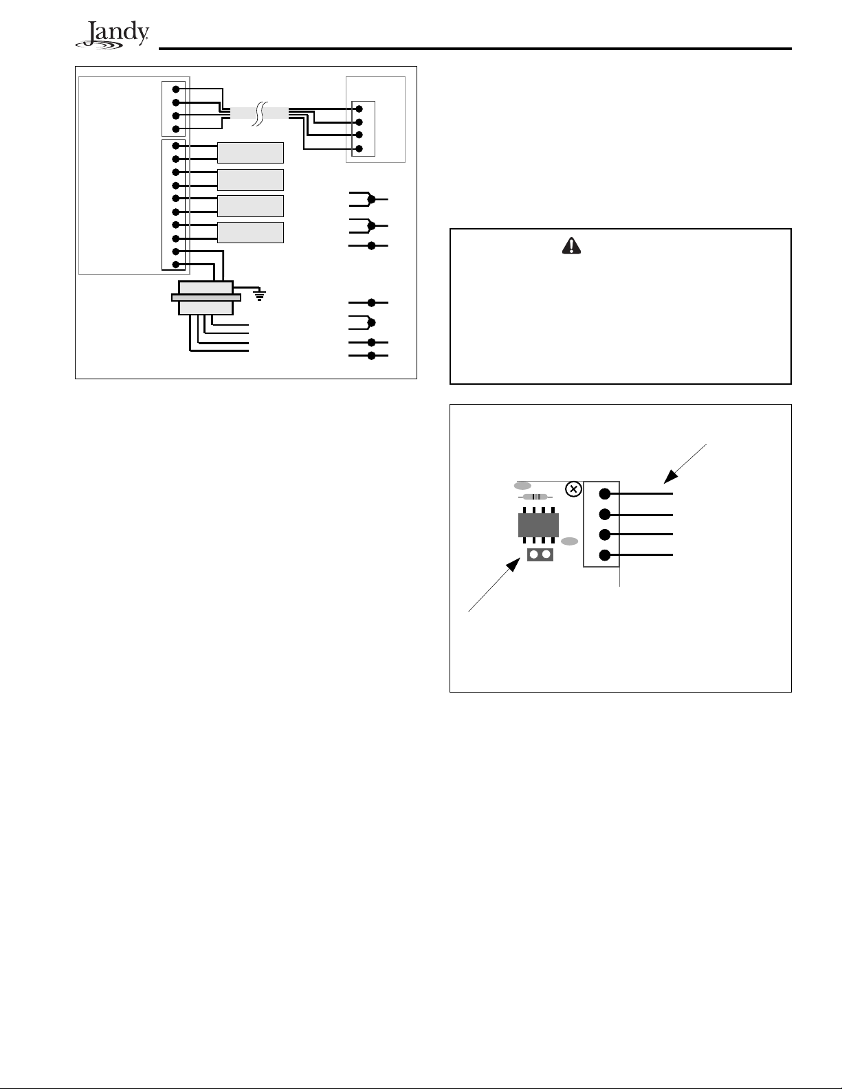
Figure 5. LPC4 Wiring Diagram
Section 5. Low Voltage Wiring
Installation
Ensure the solenoid valve is installed in the Laminar
Flow Jet prior to starting the following procedure.
1. Route the solenoid cable in the same conduit as
the fi ber optic.
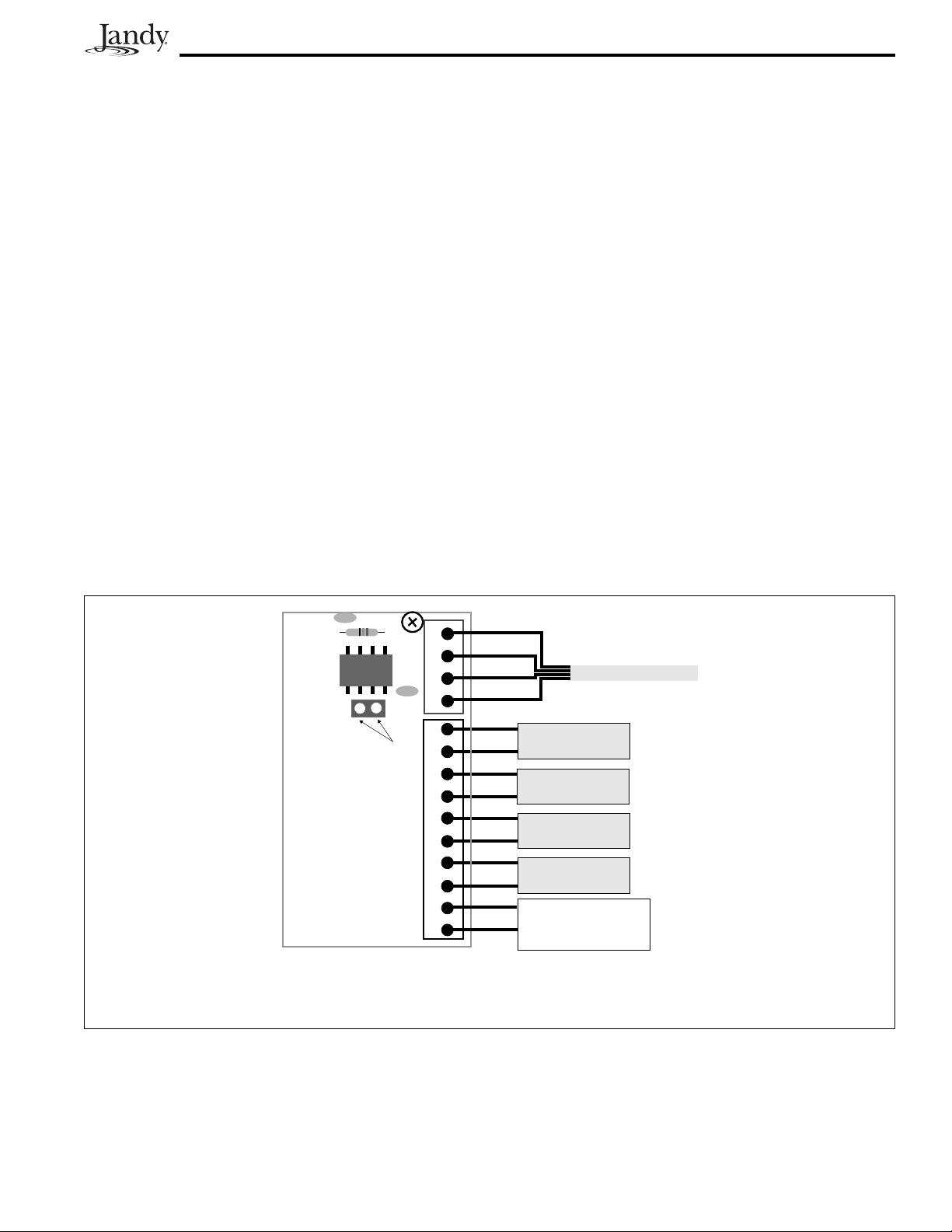
NOTE A jumper is included in the LPC4 Remote Control
Panel (LPC4-R) that allows the control panel
to provide power to the LPC4 Remote. Install
this jumper on the 2-pin header on the control
panel PCB only when connecting the LPC4
control panel to the LPC4 Remote or connecting
multiple control panels to the remote panel (see
Figure 6).
CAUTION
When connecting multiple control panels to the
LPC4 Remote, install the jumper on the header
of only one control panel.
Do not install this jumper if connecting the LPC4
control panel to a Jandy AquaLink RS system.
Red 4-pin
Terminal Bar
C13
C12
D4
GRN
4
YEL
321
BLK
RED
2. Connect the wires of each solenoid into the green
10-pin terminal bar. Refer to Figure 5 for the
connection location for each solenoid wire.
NOTE Use 1/8” screwdriver to tighten terminal screws
fi rmly. Route the solenoid wires on left side of
control panel.
3. If using the LPC4 Remote or a Jandy AquaLink
RS control panel, connect the 4-conductor wire
to the red terminal bar in the control panel. Refer
to Figure 5 for the connection location for each
wire. Tighten the terminal screws fi rmly.
2-pin Header for Jumper
Note: Install Jumper only in the LPC4 Control Board
when connecting the LPC4 Control Panel to
the LPCR1001 Remote Panel.
Figure 6. Jumper Installation in the LPC4 Control
Board - Cut Away View
4. Reconnect the 10-pin terminal bar to the back
of the control panel. Install the top cover using
the two (2) screws removed in Section 4,
Step 1.
Page 8

Page 8
Section 6. Control Panel Operation
R
a
n
d
o
Off
Group
Single
m
P
a
Slow
Fast
Remote
t
t
e
r
n
Fast
d
e
m
Med
i
T
Slow
Off
Figure 7. LPC4 Control Panel Knob
The LPC4 control panel knob has nine (9) operable
settings (see Figure 7). The operating positions are
as follows:
• OFF - Turns off all pulse control to all Laminar
Jets.
• Timed - Provides a synchronous pulse to all
Laminar Jets in any one of the following three
(3) timed settings.
Slow - Pulse occurs every eight (8) seconds
Medium - Pulse occurs every four (4) seconds
Fast - Pulse occurs every one (1) second
Section 7. LPC4 Remote Installation
The LPC4 Remote allows you to operate the control
panel from alternate locations.
1. Remove the four (4) screws located under the
spring-loaded cover on the remote panel.
Remove the cover and set aside.
NOTE The remote panel PCB is located on the back of
the cover.
2. Locate the four (4) mounting holes available on
the remote panel. Mount the remote panel to a
vertical surface.
3. Install a conduit fi tting securely into the remote
panel knockout, making sure that the fi tting is
seated fl at against the remote panel. This will
ensure a watertight seal.
4. Run a 4-conductor 22-gauge, color-coded cable
in a conduit from the LPC4 control panel to the
location for the LPC4-R remote panel.
5. On the remote panel PCB, locate the red, 4-pin
terminal bar. Connect the 4-conductor wire
to the terminal bar on the remote panel (see
Figure 5, page 7). Tighten the terminal screws
fi rmly.
6. Install the remote panel cover using the four (4)
screws removed in Step 1.
• Random - Provides pulse to Laminar Jets at
random time intervals.
Group - All Laminar Jets pulse at random
Single - Each Laminar Jet pulses at random
• Pattern - Provides a pulse sequence to all Laminar
Jets in any one of the following two (2) timed
settings.
Slow - Sequence is time delayed at slow
speed
Fast - Sequence is time delayed at rapid
speed
Remote - Transfers control of all functions to the
•
optional Remote Panel or Jandy AquaLink RS
control panel.
Section 8. Remote Panel Operation
To transfer control to the remote panel or the Jandy
AquaLink RS, turn the LPC4 control panel knob to
the Remote operating position (see Figure 7). The
remote panel can then control the pulse functions of
the Laminar Jets.
Page 9
Section 9. System Wiring Diagrams
The LPC4 system can be confi gured for various
system set ups, including the following:
• Single controller
• Single controller with LPC4-R Remote Panel
• Multiple controllers and one LPC4-R Remote
Panel
• Single controller operated by the Jandy AquaLink
RS
Page 9
• Multiple controllers operated by the Jandy
AquaLink RS
NOTE When connecting to a Jandy AquaLink RS, ensure
that the LPC4 control panel PCB is revision
P090r4 or later.
Refer to the wiring diagrams, Figures 8 through 12, on
the following pages to view system confi gurations.
C13
4
321
C12
D4
No Jumper
Installed
8
765109
GRN
YEL
BLK
RED
SOLENOID 4
SOLENOID 3
LPC4 CONTROL PANEL PCB
Note: Install Jumper only in the LPC4 Control Board
when connecting the LPC4 Control Panel to
the LPC4-R Remote Panel.
Figure 8. LPC4 Wiring, Single Controller
SOLENOID 2
4
321
BRN
BRN
SOLENOID 1
24VAC
TRANSFORMER
Page 10

Page 10
LPC4 REMOTE
C13
C12
D4
GRN
4
YEL
321
BLK
RED
RED
BLK
YEL
GRN
4321
Jumper
Installed
8
765109
SOLENOID 4
SOLENOID 3
SOLENOID 2
LPC4 CONTROL PANEL PCB
4
321
BRN
BRN
SOLENOID 1
24VAC
TRANSFORMER
Note: Install Jumper only in the LPC4 Control Board
when connecting the LPC4 Control Panel to
the LPC4-R Remote Panel.
Figure 9. LPC4 Wiring, One Controller with an LPCR1001 Remote Panel
LPC4 REMOTE
RED
BLK
YEL
GRN
GRN
YEL
BLK
RED
4321
LPC4 CONTROL PANEL PCB
C13
Jumper
Installed
4
321
C12
D4
8
765109
4
321
GRN
YEL
BLK
RED
SOLENOID 4
SOLENOID 3
SOLENOID 2
SOLENOID 1
C13
D4
No Jumper
Installed
C12
BRN
BRN
24VAC
TRANSFORMER
LPC4 CONTROL PANEL PCB
Note: Install Jumper only in the LPC4 Control Board
when connecting the LPC4 Control Panel to
the LPC4-R Remote Panel.
When connecting multiple control panels to
the LPC4 Remote, install the jumper on the
header of only one control panel.
Figure 10. LPC4 Wiring, Multiple Controllers with an LPCR1001 Remote Panel
4
321
GRN
YEL
BLK
RED
SOLENOID 4
8
765109
SOLENOID 3
SOLENOID 2
4
321
SOLENOID 1
BRN
BRN
24VAC
TRANSFORMER
Page 11

RED
BLK
YEL
GRN
Dip Switch Settings
Factory Set Optional Set
#OFF
ON
1Aux1
Cleaner
2 spd pump
21spdpump
3Aux3
Spa Spillover
4 Cool Down
Disabled
5 See Manual
See Manual
6 Spare Aux Pool
SpareAux Spa
7 Not Used
Not Used
8 Gas Heater
Heat Pump
artment)
Red
Black
Green
Yellow
Green
Black
Red
4321 654321
ToRemote
ToController
(brown term. bar)
(red term. bar)
Relay Sockets (24 VDC output)
F.Pump Aux. 1 Aux. 2 Aux. 3
Freeze/
White
Brown
Blue
Red
Not Used
Not Used
10987654321
ToSensors, etc.
(green term. bar)
Solar
Sensor
Air Sensor
Water Temp .
Sensor
Return
Voltage
Intake
Black
Red
Black
Low
Heater
JVA
(24 VAC output)
Relay Sockets (24 VDC output)
JVA
Cleaner
JVA
JVASockets
Aux. 7Aux.6Aux. 5Aux. 4
Solar
JVA
Elect.
Heater
Solar
Pump
Relay Sockets
(24 VDC output)
Battery
(9Volt)
Page 11
Jandy AquaLink RS
Remote
Filter Pump Relay
age wire in this comp
Aux. 1 Relay
age Raceway (do not run high volt
Line Two
Line One
Low Volt
Load One
Aux. 3 Relay
Aux. 2 Relay
Load Two
Aux. 4 Relay Aux. 7 Relay
Grounding Bar
Aux. 6 RelayAux. 5 Relay
System Power
120 VAC Power
Wire Nut to
Jandy AquaLink RS
C13
4
321
C12
D4
No Jumper
Installed
8
765109
GRN
YEL
BLK
RED
SOLENOID 4
SOLENOID 3
SOLENOID 2
LPC4 CONTROL PANEL PCB
4
321
SOLENOID 1
BRN
BRN
TRANSFORMER
Figure 11. LPC4 Wiring, One Controller with a Jandy AquaLink RS
CAUTION
Do not install this jumper if connecting the LPC4
control panel to a Jandy AquaLink RS system.
24VAC
Page 12

Page 12
RED
BLK
YEL
GRN
Dip Switch Settings
Factory Set Optional Set
#OFF
ON
Cleaner
1Aux1
2 spd pump
21spdpump
Spa Spillover
3Aux3
Disabled
4 Cool Down
See Manual
5 See Manual
SpareAux Spa
6 SpareAux Pool
Not Used
7NotUsed
Heat Pump
8 Gas Heater
artment)
Red
Black
Yell ow
Green
Black
Red
4321 654321
To Re mo te
ToController
(brown term. bar)
(red term. bar)
Relay Sockets (24 VDC output)
F.Pump Aux. 1 Aux. 2 Aux. 3
Green
White
Brown
Blue
Not Used
10987654321
ater Temp.
Solar
Sensor
age
Freeze/
Air Sensor
W
Sensor
Red
Black
Not Used
Red
Black
Low Volt
ToSensors, etc.
(green term. bar)
Relay Sockets (24 VDC output)
Heater
Intake
JVA
Return
JVA
Cleaner
JVA
JVASockets
(24 VAC output)
Aux. 7Aux. 6Aux. 5Aux. 4
Solar
JVA
Elect.
Heater
Solar
Pump
Relay Sockets
(24 VDC output)
Battery
(9Volt)
Jandy AquaLink RS
Remote
C13
Filter Pump Relay
age wire in this comp
Aux. 1 Relay
age Raceway (do not run high volt
Line One
Low Volt
Load One
Aux. 3 Relay
Aux. 2 Relay
Line Two
Load Two
Aux. 4 Relay Aux. 7 Relay
Grounding Bar
Aux. 6 RelayAux. 5 Relay
System Power
Wire Nut to
120 VAC Power
Jandy AquaLink RS
GRN
YEL
BLKBLK
RED
4
321
C12
D4
GRN
YEL
YEL
BLK
RED
C13
4
321
C12
D4
GRN
YEL
BLK
RED
No Jumper
Installed
8
765109
SOLENOID 4
SOLENOID 3
No Jumper
Installed
SOLENOID 2
LPC4 CONTROL PANEL PCB
4
321
SOLENOID 1
LPC4 CONTROL PANEL PCB
BRN
BRN
24VAC
TRANSFORMER
Figure 12. LPC4 Wiring, Multiple Controllers with a Jandy AquaLink RS
CAUTION
Do not install this jumper if connecting the LPC4
control panel to a Jandy AquaLink RS system.
SOLENOID 4
8
765109
SOLENOID 3
SOLENOID 2
4
321
SOLENOID 1
BRN
BRN
24VAC
TRANSFORMER
Page 13

Section 10. Parts List and
Exploded View
Number Description Part
Number
1 LPC4 Control Panel PCB,
Dead Panel w/Stand-offs,
Knob and Screws
2 Transformer R0410400
3 Control Panel Box,
w/Brackets and Screws
4 Solenoid Spring, Hammer,
and Pad (qty. 4)
5 Remote Panel PCB w/Red
Connector and Knob
6 Solenoid w/50 ft cable,
Spring, Hammer and Pad
7 LPC4 Remote LPC4-R
8 LPC4 Controller and 2
Solenoids
(each Solenoid w/50 ft cable)
R0410300
R0410500
R0410600
R0410800
LPC4-S
LPC4
Page 13
4
6, 8 (x2)
10 ¼
32
1
5
7
8
6¾
"
2¾"
"
10 ¼
5
9
/16"
"
5"
5
/8"
4
5¼"
4
"
5¾
"
Side View Front View
LPC4 Control Panel Dimensions
3½"
37/8"
Side View Front View
LPC4 Remote Panel Dimensions
Page 14

Page 14
NOTES
Page 15

Page 16

LIMITED WARRANTY
Thank you for purchasing Jandy® pool and spa products. Jandy Pool Products, Inc. warrants all parts to be free
from manufacturing defects in materials and workmanship for a period of one year from the date of retail
purchase, with the following exceptions:
AquaLink® RS units installed with Jandy Surge Protection Kits will be covered for two years.
•
NeverLube® valves are warranted for the life of pool and/or spa on which they were originally installed.
•
AquaPureTM Electronic Chlorine Generator Electrolytic Cells carry a 5 year limited warranty on a prorated basis.
•
This warranty is limited to the first retail purchaser, is not transferable, and does not apply to products that have
been moved from their original installation sites. The liability of Jandy Pool Products, Inc. shall not exceed the
repair or replacement of defective parts and does not include any costs for labor to remove and reinstall the
defective part, transportation to or from the factory, and any other materials required to make the repair. This
warranty does not cover failures or malfunctions resulting from the following:
1. Failure to properly install, operate or maintain the product(s) in accordance with our published Installation,
Operation and Maintenance Manuals provided with the product(s).
2. The workmanship of any installer of the product(s).
3. Not maintaining a proper chemical balance in your pool and/or spa [pH level between 7.2 and 7.8, Total
Alkalinity (TA) between 80 to 120 ppm, Total Dissolved Solids (TDS) less than 2000 not including salt ppm].
4. Abuse, alteration, accident, fire, flood, lightning, rodents, insects, negligence or acts of God.
5. Scaling, freezing, or other conditions causing inadequate water circulation.
6. Operating the product(s) at water flow rates outside the published minimum and maximum specifications.
7. Use of non-factory authorized parts or accessories in conjunction with the product(s).
8. Chemical contamination of combustion air or improper use of sanitizing chemicals, such as introducing
sanitizing chemicals upstream of the heater and cleaner hose or through the skimmer.
9. Overheating; incorrect wire runs; improper electrical supply; collateral damage caused by failure of O-Rings,
DE grids, or cartridge elements; or damage caused by running the pump with insufficient quantities of water.
LIMITATION OF LIABILITY:
This is the only warranty given by Jandy Pool Products, Inc. No one is authorized to make any other warranties
on behalf of Jandy Pool Products, Inc. THIS WARRANTY IS IN LIEU OF ALL OTHER WARRANTIES,
EXPRESSED OR IMPLIED, INCLUDING BUT NOT LIMITED TO ANY IMPLIED WARRANTIES OF FITNESS
FOR A PARTICULAR PURPOSE AND MERCHANTABILITY. JANDY POOL PRODUCTS, INC. EXPRESSLY
DISCLAIMS AND EXCLUDES ANY LIABILITY FOR CONSEQUENTIAL, INCIDENTAL, INDIRECT OR
PUNITIVE DAMAGES FOR BREACH OF ANY EXPRESSED OR IMPLIED WARRANTY. This warranty gives
you specific legal rights. You may also have other rights which vary by state or province.
WARRANTY CLAIMS:
For prompt warranty consideration, contact your dealer and provide the following information: proof of purchase,
model number, serial number and date of installation. The installer will contact the factory for instructions
regarding the claim and to determine the location of the nearest designated service center. If the dealer is not
available, you can locate a service center in your area by visiting www.jandy.com or by calling our technical
support department at (707) 776-8200 extension 260. All returned parts must have a Returned Material
Authorization number to be evaluated under the terms of this warranty.
H0566900A
6000 Condor Drive • Moorpark, CA USA 93021 • 707.776.8200 • Fax 707.763.7785
Litho in U.S.A. © Jandy Pool Products, Inc. 0509
Jandy Pool Products, Inc.
 Loading...