

Page 1
Installation and Operating Data
Installation and
Operation Manual
Jandy® Laminar
Jet with Deck Box
WARNING
FOR YOUR SAFETY - This product must be installed and serviced by a pro fes sion al pool/spa
service technician. The procedures in this manual must be followed ex act ly. Failure to follow
warning notices and instructions may result in property damage, serious injury, or death.
This manual contains important information about the installation, operation and safe use of
this product. This information should be given to the owner/operator of this equipment.
H0565200B
Page 2

Page 3

Page 3
Section 1. General Installation
Requirements
This document gives in struc tions for installing the
Jandy Laminar Jet. Read through the in struc tions
com plete ly before starting the pro ce dure.
The Jandy Laminar Jet is designed to provide a clear
stream of water that arcs up to a maximum of seven
feet (7') high and eight feet (8') out into the water.
Its design provides for the option to light the arc of
water with fi ber optics creating a daz zling nightime
effect. This unique water feature is easily installed and
multiple jets can be com bined to create spec tac u lar
water en ter tain ment.
To properly install this product please review the
following installation and main te nance in struc tions.
1.1 Water Source
The Laminar Jet water supply line must be fi ltered
by a cartridge fi lter (do not use a sand fi lter). If you
are using a dedicated fi lter - it must be a minimum of
20 square feet. For multiple jet installations, use 100
square feet, such as the Jandy CT100.
1.5 Critical Placement Dimensions
The Laminar Jet can project a maximum of seven feet
(7') up and eight feet (8') out into the water. Therefore,
ensure the installation is no more than six feet (6')
from the inside edge of the pool.
NOTE To avoid water spray on the deck in high wind
areas, place the Laminar Jet closer to the edge
of the pool.
NOTE The Deck Box lid can only rotate approximately 30
degrees to the left or the right. Therefore, make
sure that the Deck Box is positioned towards the
desired target location (see Section 2) prior to
completing the installation.
1.6 Bonding
NOTE Only units with metal mounting brackets require
bonding.
The Laminar Jet assembly mounting brackets (metal
only) must be bonded to the pool/spa structure using a
solid copper conductor, No. 8 A WG or lar ger. Prepare
the unit for bonding prior to installation. Bond the
unit using the external lug provided to a steel rod in
the deck frame or metal piping within fi ve feet (5’)
of the inside walls of the pool.
1.2 Pump
Required minimum pump fl ow for each Laminar
Jet is approximately 10 gallons per minute (gpm).
If a dedicated pump is used, a minimum of ½ HP is
required and the pump must produce the required fl ow
at a minimum of sixteen feet (16') of head.
1.3 Plumbing
Each Laminar Jet requires a 1½" to 2" PVC main
feed line with 1" PVC entering the Deck Box. An
adjustment valve and a check valve are also required.
Valves should be placed as far from the Deck Box
as possible to minimize water turbulence (refer to
Figures 1 and 2 and Table 1).
1.4 Conduit/Fiber Optics (Optional)
If installing fiber optics, each Laminar Jet will
require 100 to 150 strand fi ber optic cable. 150 strand
cable is recommended due to the enhanced lighting
effects. Install a 120 VAC line as per the fi ber optic
manufacturer and local code requirements.
Locate the four bonding lugs on the unit. One lug
is mounted on each side of the jet assembly metal
mounting bracket (2 total). One lug is mounted on
the inner wall of the Deck Box above the water inlet
standpipe. The remaining lug is mounted on the outer
wall of the box, directly connected to the inner lug.
Page 4
Page 4
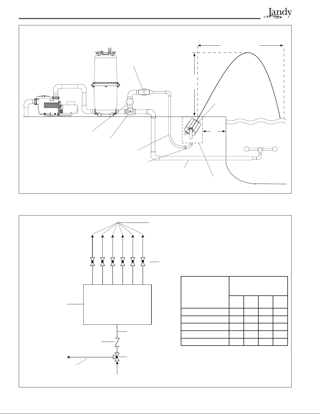
Pump
Filter
Adjustment Valve
(Globe Valve
Recommended)
Water Throw
8' Maximum
Water Height
7' Maximum
Jandy Laminar
Nozzle
Check Valve
Jandy 3-Port Valve
Use 5 feet of 1" PVC flex pipe.
Use 1” sweep elbow.
2" Pipe
Figure 1. Basic Plumbing Diagram for Laminar Jet with Deck Box
"C" -
Inlet Lines to
Laminar Jet Deck
Box
(Maximum 6 Lines
per Plumbing Loop)
Globe Valves
"B" - Plumbing
Loop
"A" - Main Feed Line
Check Valve
6'
max
Laminar Deck Box
Table 1. Multiple Jet Setup
Number of Deck
Jets at rate of 10
GPM
(gallons per
minute)
2 1½" 1"
3 1½" 1½"
4 2" 1½"
5 2" 1½"
6 2" 1½"
Return Lines
Recommended Pipe
Size within 25' of
equipment
ABCD
1"
1"
1"
1"
1"
1½"
1½"
2"
2"
2"
Jandy 3-Port Valve
"A"
"D" - Bypass/Bleed Off Line
(P/N 4715 if
Note: If using a high head pump,
plumb a cartridge filter inline.
Figure 2. Plan View of Plumbing Loop for Multiple Laminar Jets
is 1½" or P/N 4717 if "A" is 2")
Page 5

Page 5
Section 2. Installing the Deck Box
NOTE Prior to installing the Jandy Laminar Jet Deck Box,
locate the jet opening (slot) in the Deck Box cover.
Make sure that this opening is pointing towards
the desired target location in the pool. Use the
water stand pipe as a reference (see Figure 3).
Determining the orientation of the Deck Box will
also establish where to place the plumbing and
fi ber optic conduit.
Water Output
Deck Box
Lid with Slot
Deck Material Deck Material
Laminar
Jet
Assembly
Water Inlet to
Jet Assembly
(2 - 1/2" Unions)
Deck Box Lid
Adjustable Collar
Deck Box
Water
Standpipe
Sweep Elbow
1" Laminar Jet
Water Supply
2. Lift up the Deck Box lid and adjustable
deck lid collar from the Deck Box (see
Figure 4). Notice that the Laminar Jet assembly
is connected to the Deck Box lid as one unit.
Disconnect the two (2) ½” unions located on
the bottom of the Laminar Jet assembly (see
Figure 3). Set the lid/jet assembly aside.
13 ¾"
12"
21"
18"
1" Fiber
Optic Conduit
Figure 3. Laminar Jet Deck Box Schematic
NOTE The Deck Box lid can only rotate approximately 30
degrees to the left or the right. Therefore, make
sure that the Deck Box is positioned towards the
desired target location prior to completing the
installation.
1 1/2" Drain
Line
2.1 In-deck Installation
1. Dig the hole for the Deck Box approximately
twenty-four inches (24”) deep and eighteen
inches (18”) in diameter. This will ensure enough
room for positioning the box and laying out the
plumbing. This depth also allows for the addition
of a layer of pea gravel (1/8 to ¼ size) for stability
and additional drainage.
Figure 4. Deck Box Dimensions
3. Set the Deck Box in the hole. The Deck Box
should sit deep enough so that the upper edge
of the box will be approximately one and one
half to two inches (1½”-2”) below the surface
of the finished deck, after the deck material is
poured.
NOTE T o ensure that the box stays upright while installing
and leveling the unit, place a six inch (6”) length
of one and one half inch (1½”) PVC pipe in the
construction support socket located on the bottom
of the box (see Figure 5).
4. Level the Deck Box. To hold the box in place
while the deck is poured, secure the box by
tying it with tie wire to the steel framework of
the deck.
Page 6

Page 6
5. Plumb the incoming, filtered water supply
to the one inch (1") hub located on the
bottom of the Deck Box marked
Inlet (see
Figure 5). The filtered water supply must
include an adjustment valve and check valve
(see Figures 1 and 2 ).
Construction Support
Socket (1½")
Water Inlet (1")
Drain (1½")
8. (For units with metal mounting brackets only .)
To bond the Laminar Jet, connect one end of a
copper wire to the external lug located on the
box bottom and the other end to the steel frame
of the deck.
9. Verify the Deck Box is level.
10. Place the adjustable deck lid collar back on the
box. This collar allows the installer to make fine
adjustments when leveling the box to be flush
with the deck's finished surface. Set the collar
at the finished deck level and pour the deck.
2.2 Out-of-deck/Planter Box Installation
NOTE Do not install the Jandy Laminar Jet Deck Box in
an area prone to run-off or fl ooding.
NOTE The Deck Box lid can only rotate approximately 30
degrees to the left or the right. Therefore, make
sure that the Deck Box is positioned towards the
desired target location prior to completing the
installation.
Fiber Optic/Low Voltage
Electrial Inlet (1")
Figure 5. Deck Box - Bottom View
Caution
Deck Box is made of ABS. Use Weld-On 793
or 794 ABS-PVC Cement to glue Schedule 40
PVC.
6. Plumb the conduit for the fiber optic cable to
the one inch (1") hub located on the bottom of
the Deck Box marked
Electrical
(see Figure 5). Refer to Section 3 for
Fiber Optic/Low V oltage
fiber optic installation.
NOTE This hub is also used to install the two (2)
conductor, eighteen (18) gauge, stranded cable
for the optional LPC4 light pulse control system.
7. Plumb in the one and one-half inch (1½") drain
line marked Drain. Adequate drainage must be
provided to box.
NOTE Proper drainage to the Deck Box is critical to avoid
damage to the Laminar Jet assembly.
1. Dig the hole for the Deck Box approximately
twenty-four inches (24") deep and eighteen
inches (18") in diameter. This will ensure enough
room for positioning the box and laying out
the plumbing. The dimensions allow for the
addition of a layer of pea gravel (1/8 to 1/4 size)
for drainage, as well as room to pour concrete
around the outside of the box for stability.
NOTE Proper drainage to the Deck Box is critical to avoid
damage to the Laminar Jet assembly.
2. Lift up the lid/jet assembly and adjustable deck
lid collar from the Deck Box. Disconnect the
two (2) ½" unions located on the bottom of the
Laminar Jet. Set the lid/jet assembly aside.
NOTE T o ensure that the box stays upright while installing
and leveling the unit, place a six inch (6") length
of one and one half inch (1½") PVC pipe in the
construction support socket located on the bottom
of the box (see Figure 5).
3. Set the Deck Box in the hole. The box should
be approximately one and one-half to two
inches (1½"-2") above the finished grade in the
planter.
Page 7

Page 7
NOTE Unlike the in-deck installation, the Deck Box cover
cannot be fl ush with the fi nished grade. It must sit
slighty above the surface to prevent water and
debris from seeping into the box.
4. Level the Deck Box. To hold the box in place,
position a six inch (6") length of one and one
half inch (1½") PVC pipe is needed in the
construction support socket located on the
bottom of the box (see Figure 5). In include an
adjustment valve and check valve (see Figures
1 and 2).
5. Plumb the incoming, filtered water supply
to the one inch (1”) hub located on the
bottom of the Deck Box marked Inlet (see
Figure 5). The filtered water supply must include
an adjustment valve and check valve (see
Figures 1 and 2 ).
Caution
Deck Box is made of ABS. Use Weld-On 793
or 794 ABS-PVC Cement to glue Schedule 40
PVC.
2.3 Pressure Test Water Lines
Connect the two (2) ½" unions removed from the
Laminar Jet in Section 2.1, Step 2 (or Section 2.2,
Step 2 for out-of deck installation) together. This
will provide an air/water tight closed loop during the
pressure test.
NOTE This same procedure can be used if you need to
winterize the system or service the unit.
2.4 Flush Water Lines
It is important that prior to reinstalling the Laminar
Jet and Deck Box lid, the installer must turn on the
water source and fl ush the lines of any debris.
6. Plumb the conduit for the fiber optic cable to
the one inch (1") hub located on the bottom of
the Deck Box marked Fiber Optic/Low V oltage
Electrical
. Refer to Section 3 for fiber optic
installation.
NOTE This hub is also used to install the two (2)
conductor, eighteen (18) gauge, stranded cable
for the optional LPC4 light pulse control system.
7. Plumb in the one and one-half inch (1½") drain
line marked Drain. Adequate drainage must be
provided to box.
8. (For units with metal mounting brackets only .)
Connect one end of a copper wire to the external
lug located on the box bottom. Connect the other
end to the steel rod used to stake the Deck Box,
or bond per the National Electrical Code.
9. Fill in the hole surrounding the Deck Box with
concrete or suitable backfill material for stability
in the ground.
10. Place the adjustable deck lid collar back on the
box.
Page 8

Page 8
Section 3. Fiber Optic Installation
3.1 Items Required
Tools
Cable
Illuminator
Additional
Materials
3.2 Installation
1. Remove six inches (6") of the cable jacket.
2. Using black electrical tape, tightly tape over the
exposed fiber leaving approximately ½" exposed
fiber at the end of the cable. The tape prevents the
individual fibers from separating.
Utility knife or hot knife; Heat gun or
propane torch.
Each jet requires 100 to 150 strands
of fiber optic cable. Do not use
more than forty feet (40') of cable
per nozzle as light output will be
diminished.
Use illuminator with sufficient
capacity of lighting effect intended.
Electrical tape; Silicon (RTV)
Section 4. Starting the System
4.1 Install Jet Assembly
1. Disconnect the two unions that were attached
together for pressure testing in Section 2.3.
2. Flush water lines to clear debris. Lines must be
clear of debris before attaching the Laminar
Jet assembly.
3. Connect the two unions to the appropriate
ports of Laminar Jet and Deck Box lid.
4.2 Set up Jet
Recall that the Deck Box lid and Laminar Jet are
attached to each other. To aim the jet, turn the lid
with the slot facing the pool until the stream reaches
the intended target area of the pool.
1. Turn on the water at a reduced rate and slowly
fill the unit. When the unit is filled, increase
the water supply until the jet streams reach
their intended targets.
3. With a heat knife, cut the fiber optic cable so that
the cable end is a flat surface. For best results, heat
knife to cherry red.
NOTE Do not cut the fi ber ends too close to the taped edge.
Leave a ¼" distance between the cable end and the
end of the taped edge. This will prevent adhesive on
the tape from melting and getting on the ends of the
fi ber optic strands.
4. Slide the completed fiber optic cable through the
Heyco waterproof fitting and up the tube (located at
the bottom of the jet) until the cable bottoms out on
the lens inside unit. Secure the fiber by tightening
the waterproof fitting.
NOTE Allow at least two feet (2') of extra fi ber optic cable
in the Deck Box to allow the Laminar Jet to be easily
removed.
5. Fill the electrical conduit between the opening and
the fiber optic cable with RTV silicon to prevent
water from entering the conduit. Let dry . The unit
is now ready for operation.
2. Use the main valve at the equipment pad to
make final adjustments to the overall water
height of the jets.
NOTE Laminar Jets are sensitive to wind, earth
movement and equipment vibration. Secure the
Laminar Jet and Deck Box to minimize vibration.
Periodic stream distortion caused by pump
vibrations and motor electrical fl uctuations is
normal and not indicative of a nozzle defect.
Also, occasionally a nozzle will “burp” due to
pumped air collecting in the nozzle body . This is
normal and will occur until all air is purged from
the piping system. Trapped air can also cause
slight distortion in water action. It is imperative
that all air is removed to ensure proper water
feature operation.
6. Install illuminator and attach fiber optic cable
according to instructions supplied with the
illuminator.
Page 9

Page 9
NOTE To adjust the angle of the jet, lift the Deck Box lid
and move the Laminar Jet up or down to increase
or decrease the angle. The angle can be adjusted
approximately 15 degrees. The Laminar Jet is
installed on two pivots. Loosen the union nuts on
the pivots and adjust the jet angle. Once you are
satisfi ed with the angle and location of the jet,
tighten the union nuts. Secure the Deck Box lid to
the Deck box collar, using two #10 by 1½", Phillips,
fl at head stainless steel screws (see Figure 6). It
is recommended to drill 1/8" pilot holes in the lid.
Then the screws can be threaded into the holes.
This will complete the installation and secure the
jet from movement.
Phillips-head
Screws
Jet Slot
Opening
Deck Box
Lid
Deck Lid
Adjustable
Collar
3. Using a garden hose, place the hose over the jet
nozzle and force water backward through the
unit and out the two ½" open unions. This will
clear debris buildup.
NOTE Avoid damage to the nozzle opening. After clean
up, reinstall the unions and reattach the unit to
the Deck Box.
5.2 Winterization
The Laminar Jet can be winterized in regions that
require winterization.
1. Remove the Deck Box lid assembly and unscrew
the two ½" unions.
2. Attach the two unions to each other to create
an air/water tight system. The Laminar Jet can
then be replaced in the Deck Box or may be
removed to a storage location. If left in the Deck
Box, tape over the slot opening to ensure no
water will enter the system. If fiber optic cable
is used, be sure to remove the retaining nut on
the waterproof fitting on the bottom of the jet
assembly.
Figure 6. Deck Box Lid with Collar
Section 5. General Maintenance and
Troubleshooting
Perform routine maintenance on the fi lter to ensure
trouble-free nozzle operation. Be careful not to allow
debris to enter the inlet plumbing when cleaning
filters. Always flush lines after cleaning and
backwash of fi lters.
5.1 Clogged Nozzle
1. If nozzle becomes clogged with debris, remove
the nozzle by unscrewing the two Deck Box lid
retaining screws.
2. Remove the Deck Box lid assembly and place on
the deck. Disconnect the two ½" unions located
on the bottom of the jet assembly.
Page 10

Page 10
Section 6. Parts List and Exploded
View
Key
No.
Description Qty. Order
Part No.
4, 6
1 Laminar Jet Body
Coupling Nut O-rings
Union O-rings
2 Thermoplastic Brackets
Screws
3 Coupling Nuts
Blank Caps
O-rings
4 Deck Box
Deck Box Lid Screws
1
2
2
2
6
2
2
2
1
2
R0401500
R0401600
R0401700
R0401800
5 Hayco Fitting Complete 1 R0401900
6 Hardware Kit
Laminar Jet Body Screws
Bracket Screws
Deck Box Lid Screws
Union O-rings
Coupling Nut O-rings
Laminar Jet Body
R0411000
8
6
2
2
2
1
O-ring (not shown)
7 Laminar Jet Assembly
1 JLJ1001
w/Deck Box
2, 6
3
9
8
7
6 (x8)
2
1
2, 6
3
8 Deck Box Lid, Pebble
Deck Box Collar, Pebble
9 JLJL Deck Box Lid,
1
JLJL1001
1
1 JLJL1002
Pewter
or JLJL Deck Box Lid, Black 1 JLJL1003
5
4
1, 6
Page 11

Page 11
Page 12

LIMITED WARRANTY
Thank you for purchasing Jandy® pool and spa products. Jandy Pool Products, Inc. warrants all parts to be free
from manufacturing defects in materials and workmanship for a period of one year from the date of retail
purchase, with the following exceptions:
AquaLink® RS units installed with Jandy Surge Protection Kits will be covered for two years.
•
NeverLube® valves are warranted for the life of pool and/or spa on which they were originally installed.
•
AquaPureTM Electronic Chlorine Generator Electrolytic Cells carry a 5 year limited warranty on a prorated basis.
•
This warranty is limited to the first retail purchaser, is not transferable, and does not apply to products that have
been moved from their original installation sites. The liability of Jandy Pool Products, Inc. shall not exceed the
repair or replacement of defective parts and does not include any costs for labor to remove and reinstall the
defective part, transportation to or from the factory, and any other materials required to make the repair. This
warranty does not cover failures or malfunctions resulting from the following:
1. Failure to properly install, operate or maintain the product(s) in accordance with our published Installation,
Operation and Maintenance Manuals provided with the product(s).
2. The workmanship of any installer of the product(s).
3. Not maintaining a proper chemical balance in your pool and/or spa [pH level between 7.2 and 7.8, Total
Alkalinity (TA) between 80 to 120 ppm, Total Dissolved Solids (TDS) less than 2000 not including salt ppm].
4. Abuse, alteration, accident, fire, flood, lightning, rodents, insects, negligence or acts of God.
5. Scaling, freezing, or other conditions causing inadequate water circulation.
6. Operating the product(s) at water flow rates outside the published minimum and maximum specifications.
7. Use of non-factory authorized parts or accessories in conjunction with the product(s).
8. Chemical contamination of combustion air or improper use of sanitizing chemicals, such as introducing
sanitizing chemicals upstream of the heater and cleaner hose or through the skimmer.
9. Overheating; incorrect wire runs; improper electrical supply; collateral damage caused by failure of O-Rings,
DE grids, or cartridge elements; or damage caused by running the pump with insufficient quantities of water.
LIMITATION OF LIABILITY:
This is the only warranty given by Jandy Pool Products, Inc. No one is authorized to make any other warranties
on behalf of Jandy Pool Products, Inc. THIS WARRANTY IS IN LIEU OF ALL OTHER WARRANTIES,
EXPRESSED OR IMPLIED, INCLUDING BUT NOT LIMITED TO ANY IMPLIED WARRANTIES OF FITNESS
FOR A PARTICULAR PURPOSE AND MERCHANTABILITY. JANDY POOL PRODUCTS, INC. EXPRESSLY
DISCLAIMS AND EXCLUDES ANY LIABILITY FOR CONSEQUENTIAL, INCIDENTAL, INDIRECT OR
PUNITIVE DAMAGES FOR BREACH OF ANY EXPRESSED OR IMPLIED WARRANTY. This warranty gives
you specific legal rights. You may also have other rights which vary by state or province.
WARRANTY CLAIMS:
For prompt warranty consideration, contact your dealer and provide the following information: proof of purchase,
model number, serial number and date of installation. The installer will contact the factory for instructions
regarding the claim and to determine the location of the nearest designated service center. If the dealer is not
available, you can locate a service center in your area by visiting www.jandy.com or by calling our technical
support department at (707) 776-8200 extension 260. All returned parts must have a Returned Material
Authorization number to be evaluated under the terms of this warranty.
H0565200B
6000 Condor Drive • Moorpark, CA USA 93021 • 707.776.8200 • Fax 707.763.7785
Litho in U.S.A. © Jandy Pool Products, Inc. 0508
Litho in U.S.A. © Waterpik Technologies 0401
Jandy Pool Products, Inc.
 Loading...