

Installation and Operating Data
FOR YOUR SAFETY - This product must be installed and serviced by authorized personnel, qualified in pool/spa heater installation. Improper installation and/or operation can
create carbon monoxide gas and flue gases which can cause serious injury, property
damage, or death. Improper installation and/or operation will void the warranty.
Installation and
Operation Manual
™
Hi-E2
Model EHE
Gas-Fired Pool
and Spa Heater
WARNING
If these instructions are not followed exactly, a fire or explosion may result,
causing property damage, personal injury, or death.
Do not store or use gasoline or other flammable vapors and liquids in the
vicinity of this or any other appliance.
WHAT TO DO IF YOU SMELL GAS
• Do not try to light any appliance.
• Do not touch any electrical switch; do not use any phone in your building.
• Immediately call your gas supplier from a neighbor’s phone. Follow the gas
supplier’s instructions.
• If you cannot reach your gas supplier, call the fire department.
Installation and service must be performed by a qualified installer, service
agency or the gas supplier.
H0205000F

TABLE OF CONTENTS
SECTION 1
General Information
1A Introduction ............................................................1
1B Description.............................................................1
1C Warranty ................................................................1
SECTION 2
Installation Instructions
2A General Requirements ..........................................1
2B Heater Assembly and Preparation......................... 2
2C Heater Location ..................................................... 2
2D Installation Clearances .......................................... 2
2E Outdoor Installation ...............................................2
2F Outdoor Shelter Installation (Canada) ...................3
2G Indoor Installation ..................................................3
2G-1 Preparation of Heater For
Indoor Installation ..................................................3
2G-2 Combustion Air Requirements for
One-Pipe Installation .............................................4
2G-3 Two-Pipe Installation (Direct Vent) ........................ 4
2G-3a Connection of Combustion Air Pipe....................... 4
2G-3b Piping Materials ..................................................... 5
2G-3c Size and Length of Combustion
Air and Vent Piping ................................................5
2G-3d Combustion Air and Vent Pipe Installation ............6
2G-3e Room Ventilation ...................................................7
2G-3f Inspection and Replacement of Existing Vent
System with New Components ..............................7
2H Condensate Disposal ............................................ 7
2I Gas Supply and Piping .......................................... 8
2J Electric Wiring........................................................ 9
2J-1 Electrical Power .....................................................9
2J-2 Bonding ...............................................................11
2J-3 Auxiliary Time Clock Wiring .................................11
2J-4 Remote Operation ...............................................11
2K Water Piping ........................................................ 11
2K-1 Reversal of Heater Water Connections ............... 11
2K-2 Pool/Spa Piping Systems ....................................11
2K-3 Connections at Heater .........................................13
2K-4 Pressure Relief Valve .......................................... 13
2K-5 Automatic Chlorinators (Chemical Feeders)........ 13
2L Start-Up and Adjustment ..................................... 13
2L-1 Normal Operation ................................................ 13
2L-2 Start-Up ............................................................... 14
2L-3 Condensate ......................................................... 14
2L-4 Gas Pressure.......................................................14
2L-5 Adjustment of Water Pressure Switch ................15
2L-6 Water Temperature Rise ..................................... 15
SECTION 3
Operating Instructions
3A Start-Up Procedure.............................................. 16
3B Temperature Controls..........................................17
3C Lighting and Shutdown ........................................17
3C-1 Lighting the Heater ..............................................17
3C-2 Shutdown .............................................................17
3D Water Chemistry ..................................................18
3D-1 Pools ....................................................................18
3D-2 Spas .................................................................... 18
3D-2a Spa Water Chemistry........................................... 18
3D-2b Water Changing ...................................................18
3D-2c Corrosion ............................................................. 18
3D-2d Testing ................................................................. 18
3E Spa/Hot Tub Safety Rules ................................... 18
3F Swimming Pool Energy Saving Tips ....................19
3G Seasonal Care .....................................................19
3G-1 Spring and Fall Operation.................................... 19
3G-2 Winterizing ...........................................................19
3H Periodic Inspection ..............................................20
3H-1 Owner Inspection ................................................. 20
3H-2 Professional Inspection .......................................20
SECTION 4
Maintenance and Service
4A General ................................................................21
4B Induced-Draft Combustion System...................... 21
4C Heater Components and Their Operation ........... 21
4D Combustion Air Filter ........................................... 22
4E Electrical Trouble Shooting.................................. 23
4E-1 115V Electrical Power Supply..............................23
4E-2 Control Circuit Trouble Shooting .........................23
4E-2a Transformer ......................................................... 23
4E-2b Fuse..................................................................... 23
4E-2c Fireman Switch and External Interlocks ..............24
4E-2d Limit Switches......................................................24
4E-2e Water Pressure Flow Switch................................ 24
4E-2f Temperature Control ...........................................24
4E-2g Venturi Pressure Switch ...................................... 25
4E-2h Ignition Control ....................................................25
4E-2i Burner Limit Switch .............................................. 25
4E-2j Vent Limit Switch ................................................. 25
4E-2k Combustion Blower..............................................26
4E-2l Igniter ...................................................................26
4F Venturi Combustion Flow System........................26
4F-1 Pressure Measurement Ports .............................. 26
4F-2 Venturi System Checkout .................................... 26
4F-2a Unfired Venturi Differential Pressure ................... 26
4F-2b Gas Pressure Offset ............................................ 27
4F-2c Gas Orifice Differential ........................................ 28
4F-3 Air Flow Investigation........................................... 28
4F-3a Combustion Air Flow............................................ 28
4F-3b Flow in Heater and Vent ...................................... 28
4F-4 Fuel Gas Type and Gas Orifice Size ................... 28
4F-5 High Elevation Operation .....................................29
4G Combustion Condensate ..................................... 29
4H Major Component Service ................................... 29
SECTION 5
Capacities and Dimensions
5A General Information .............................................29
SECTION 6
Replacement Parts
6A General Information .............................................30
Hi-E2
Page 1
SECTION 1.
General Information
1A. Introduction
This manual contains information for the proper
installation and operation of the Hi-E
pool/spa heater. Certain sections are specifi c to United
States or Canadian installations, and are labeled
United States or Canada. Procedures in this manual
must be followed exactly. To obtain a copy of this
manual contact Jandy Pool Products, Inc. For address
information see back cover.
1B. Description
The Hi-E2 is a very effi cient gas-fi red pool and
spa heater. Its combustion system includes a heat
exchanger which extracts 95% of the energy in the
gas fuel. It has no standing pilot burner. It exceeds the
requirements of energy conservation regulations such
as those in California, Hawaii, New York, Oregon
and other states which require that a pool heater have
intermittent ignition.
The heater is designed to operate in conventional
swimming pool and spa equipment arrangements.
It requires 115V 60 Hz electrical power. It has the
versatile FlexTemp dual-thermostat control system for
pool/spa combinations.
The Hi-E
comply with latest editions of applicable standards.
In the United States, the applicable standard is ANSI
Standard Z21.56 for gas-fi red pool heaters. In Canada,
it is Standard CSA 4.7.
The heater has been designed specifi cally to heat
fresh water swimming pools and spas, and with proper
installation and care, it will provide years of reliable
service. Do not use it to maintain pool or spa water
temperature below 70°F. Do not use it as a heating
boiler or general service water heater or to heat salt
water. For special applications, consult your Jandy
dealer.
2 is certifi ed by CSA International to
1C. Warranty
The Hi-E2 is sold with a limited factory warranty.
A copy of the warranty is included in a plastic
bag inside the heater and on the back cover of this
manual. The home owner should fi ll out the warranty
registration card included in the plastic bag and return
it via mail. The warranty does not cover damage
caused by improper installation, operation, or fi eld
modifi cation; or damage to the heat exchanger caused
by corrosive water. See Section 3D for guidelines on
pool water chemistry.
2 Model EHE
WARNING
Improper installation or servicing can cause property damage, injury or death due to fi re, asphyxi-
ation or carbon monoxide poisoning. For indoor
installations, as an additional measure of safety,
Jandy Pool Products, Inc. strongly recommends
installation of suitable Carbon Monoxide detectors
in the vicinity of this appliance and in any adjacent
occupied spaces.
SECTION 2.
Installation Instructions
2A. General Requirements
All gas-fi red products require correct installation
to assure safe and satisfactory operation. The
requirements for pool heaters include the following:
1. Appropriate site location and clearances.
2. Suf fi cient supply of clean air for combustion and
ventilation.
3. Proper venting of products of combustion.
4. Properly sized gas pipe.
5. Properly sized gas meter.
6. Adequate water fl ow.
7. Provision for disposal of combustion condensate
water.
In the United States, installation must be in
accordance with local codes and the most recent
edition of the National Fuel Gas Code, ANSI Z223.1/
NFPA-54. The Code can be obtained from:
National Fire Protection Association
1 Batterymarch Park
Quincy, MA 02269
In Canada, install the heater in accordance with
local codes and the most recent edition of the Natural
Gas and Propane Installation Code, CAN/CSA B149.1.
Special Precautions
Liquefi ed petroleum (LP) gas is heavier than
air. Therefore, a pool heater using LP gas is subject
to special installation rules. Consult local codes and
fi re protection authorities about specifi c installation
restrictions.
Fuel gas and its combustion products are known
to cause cancer or harm the reproductive process.
Follow these installation instructions and applicable
codes exactly to avoid this.

Page 2
2B. Heater Assembly and Preparation
The Hi-E2 can be installed in a variety of ways,
some of them requiring preparation or assembly in
the fi eld. In all cases, condensate tubing and fi ttings,
which are provided with the heater, must be connected
and routed. Water connections are provided on the
right side of the heater but can be changed to the left
side by reversal of the water headers.
It is best to handle these preparations before the
heater is in its fi nal location. Instructions are provided
in subsequent sections of this document.
Installation at High Elevation
The Hi-E
2 has a venturi-type combustion system
which does not require modifi cation for operation at
high elevation. In this type of system, air and fuel gas
density changes are automatically compensated for,
assuring proper air/fuel mixture. Heating capacity is
reduced about 3 percent per 1000 feet (305 meters)
above sea level. In general, effi ciency at high elevation
is equal to or better than at sea level.
2C. Heater Location
The Hi-E2 may be installed indoors or outdoors
as outlined in later sections. When installed indoors,
combustion air will often be piped to the heater and
this requirement may affect the choice of location (see
later section on air for combustion and ventilation).
Both indoor and outdoor installations require provision
of means for disposal of combustion condensate per
section 2H.
Install the heater at least 5 feet (1.52 meters)
from the inside wall of the pool or spa unless the
heater is separated from the pool or spa by a fi ve-foot
(1.52 meter) high solid fence, wall or other permanent
barrier.
When pool equipment is located below the pool
surface, a leak from any component can cause large
scale water loss or fl ooding. Jandy Pool Products Inc.
cannot be responsible for such water loss or fl ooding
or resulting damage. Location of the heater below
or above the pool deck affects operation of its water
pressure switch. See sections on water piping and
heater start-up for more information about this.
WARNING
When pool equipment is located below the pool surface, a leak from any component can cause large
scale water loss or fl ooding. Jandy Pool Products,
Inc. cannot be responsible for such water loss or
fl ooding or resulting damage.
Locate the heater in an area where water
leakage will not result in damage to the area around
the appliance or to a structure. If forced to locate
the heater where water leakage may cause damage,
provide a suitable pan with drain under the heater. This
pan must not restrict air fl ow or heater functions.
In selection of a location, disposal of combustion
condensate must also be considered. The heater can
produce three gallons of condensate water per hour
under some operating conditions. Means to drain this
condensate must be available or special provisions,
such as a condensate pump must be provided. See later
section on condensate disposal.
2D. Installation Clearances
Clearances between the heater and combustible
material must be per Table 1.
Surface/Component Minimum Clearance
Inches (mm)
Rear & Blank Side 2 (55)
Piping Side 12 (305)
Front 18 (455)*
Top - Indoors 6 (150)
Top - Outdoors Open (See Note)
Flooring Combustible
Vent 0
* For Canada 24 inches (610 mm) clearance
Table 1. Installation Clearance Requirements.
NOTE: See Outdoor Installation section
regarding roof overhang.
These clearances are the minimum acceptable.
Whenever possible, larger clearances should be
provided to assure adequate room for service
operations. Note that gas piping must be provided
through the left side of the unit and that the
combustion air duct, when provided, also enters
through the left side. See later section on combustion
air, and also the section on water piping.
Do not install the heater on carpeting or similar
material.
2E. Outdoor Installation
Locate the heater in an open, unroofed area
and maintain the clearances shown in Table 1. Do
not locate the heater below or adjacent to any doors,
windows, louvers or grates, etc., which connect in any
way with an inhabited area of a building, even through
another building such as a garage or utility room (see
Figure 1). Do not locate the heater below an outdoor
deck, unless treated as an indoor installation with
adequate clearances and proper venting to a location
away from the deck.
Hi-E2
Figure 1. Outdoor heater location.
Page 3
If the heater is installed close to a structure,
protect it from rain water runoff by means of gutters,
roof water diverters or similar measures. Do not
locate the heater close to irrigation sprinklers. Water
from sprinklers may damage controls and electronic
components.
Because the Hi-E
2 is very effi cient, combustion
system exhaust gases are moist. Do not locate
the heater such that this exhaust will impinge on
structures or vegetation which may be damaged by
combustion condensate.
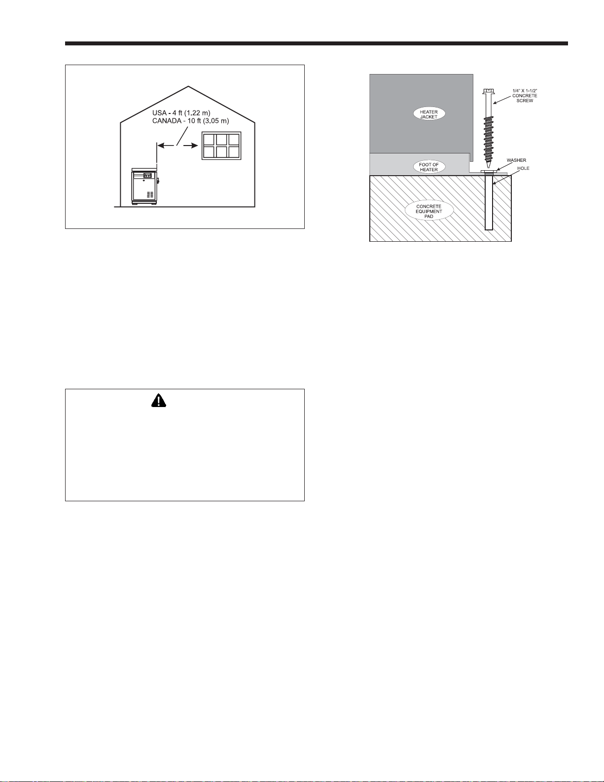
WARNING
In United States
Do not install the heater with the vent within 4 feet
(1.22 m) of any opening into a building.
In Canada
Do not install the heater with the vent within 10 feet
(3.05 m) of any opening into a building.
In Florida it is required that the heater be
se cure ly fastened to the equipment pad. Use a size
1/4" x 1-1/2" long stainless steel Tapcon® type
con crete screws and washers at each of the four
tabs located at the base of the heater. Mount ing
the ap pli ance in this manner meets the applicable
requirements of the Florida Building Code.
Mounting screws are not provided with this
heater. After placing the heater on the equipment pad,
drill a hole in the concrete at each of the four tabs
on the feet of the heater. (The correct size drill bit
is usually provided with the concrete screws when
purchased). Place a screw in each of the holes and
fasten the heater to the equipment pad (see Figure 2).
Do not over torque the screws.
2F. Outdoor Shelter Installation (Canada)
An outdoor shelter is an unoccupied enclosure
which does not communicate directly with occupied
areas. The Hi-E
2 may be installed in such a shelter
Figure 2. Anchor heater to equipment pad.
only when the installation is in accordance with local
codes and the most recent edition of the Natural Gas
and Propane Installation Code (CAN/CSA B-149.1).
These codes and standards and Jandy require that the
heater be properly vented as outlined in this manual.
Other requirements also apply, such as provision
of ample uncontaminated air for combustion and
ventilation.
2G. Indoor Installation
The Hi-E2 can be located indoors when
provided with “one-pipe” or “two-pipe” systems for
combustion air and combustion product venting. A
one-pipe installation has only a vent pipe, and air for
combustion must be provided to the room the heater
is located in. A two-pipe system (sometimes referred
to as “direct vent” or “sealed combustion”) has a vent
pipe plus a pipe bringing air directly to the heater's
combustion system.
Section 2G-2 specifi es requirements for
provision of combustion and ventilation air for onepipe installations. Section 2G-3 covers two-pipe
installation.
An important consideration in selecting one or
two pipe installation is the quality of the combustion
air. Indoor air is sometimes contaminated with
various household or pool sanitation chemicals
which can cause corrosion in the heater combustion
system. Unless the indoor air is known to be free
of these materials, two pipe installation is strongly
recommended.
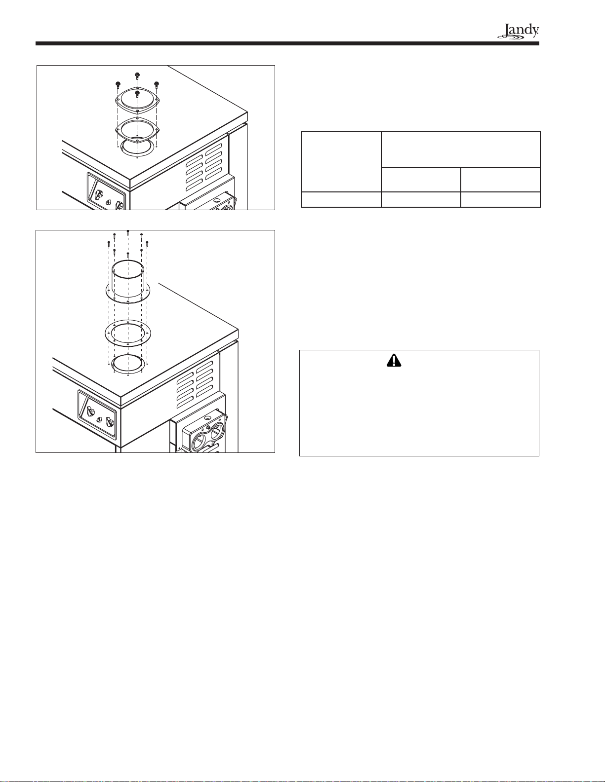
2G-1. Preparation of Heater For Indoor
Installation
If the Hi-E
discharge grille must be converted to an exhaust pipe
confi guration. The necessary vent collar, gasket and
screws are shipped packaged within the heater. The
conversion can be done quite simply as follows (see
Figures 3 and 4):
2 is to be installed indoors, its exhaust
Page 4
Figure 3. Removal of outdoor exhaust grille.
BTU/h of heater input. When air is provided indirectly
through ducts from the outside, the openings and
passages must have at least one square inch of area
per 2000 Btu/h of heater input. These requirements are
interpreted in Table 2.
Required net free area in square
Model
350 88 (570) 175 (1130)
Table 2. Required Net Free Area of Openings for
Combustion and Ventilation Air.
inches (sq. cm) for each of 2 openings
- one near ceiling and one near fl oor
Directly Through
an Exterior Wall
Through Horizon-
tal Ducts
Note that the numbers indicate the net free area
— after allowing for the blockage of grille bars, etc.
See applicable local codes and the previously-cited
national codes for details. Even though codes may
permit it, Jandy does not recommend installations
with only “infi ltration” as the means for provision of
combustion air.
See Section 2G-3c for vent pipe sizing.
Figure 4. Vent collar assembly for indoor installation.
1. Remove the vent exhaust grille by removing
the four screws which retain it. The grille, its
gasket, and the screws may be discarded.
2. Place the vent collar gasket on the top of
the heater aligning its center hole and screw
holes with those in the top of the heater.
3. Place the vent collar over the gasket and
fasten it in place with the screws and
lockwashers provided. Be sure that all
components are properly aligned. Screws
must be tightened enough to assure a sealed
joint without deforming the vent collar.
2G-2. Combustion Air Requirements for
One-Pipe Installation
One-pipe indoor installations must have specifi c
provisions for supply of combustion and ventilation
air to the room in which the heater is located. Two air
openings must be provided — one near the ceiling
and one near the fl oor. When air is provided directly
through an outside wall, each opening must have at
least one square inch (6.5 square cm) of area per 4000
WARNING
Do not store any chemicals, cleaners, or other corrosive material near combustion air openings or in
the room. Avoid location of dryer vents in the vicinity
of combustion air openings. Failure to prevent corrosive materials from mixing with combustion air
can result in reduced heater life and unsafe heater
operation.
2G-3. Two-Pipe Installation (Direct Vent)
This section specifi es installation requirements
for combustion air and vent piping for “two pipe”
installations. A two-pipe system provides isolation of
the Hi-E
2 combustion system from the space in which
the heater is installed. It has not only a vent pipe,
but also a combustion air pipe to provide air directly
from the outdoors. Research studies have shown that
contaminants which may corrode internal heater parts
are typically at much lower levels in outdoor air than
in air from indoors.
2G-3a. Connection of Combustion Air
Pipe
A collar for combustion air pipe connection is
provided in the heater at the inlet of the fi lter box.
As shown in Figure 5, the combustion air pipe is
routed through the side of the heater to the fi lter box
connection. Remove the cover plate from the left side
panel to provide access for the air pipe.
Hi-E2
Page 5
4'
Figure 5. Connection of combustion air pipe to heater.
2G-3b. Piping Materials
Vent piping must be corrosion resistant because
combustion condensate is usually present on its
internal surfaces. Only the following materials are
acceptable for vent piping:
PVC Class 100, Class 125 or Schedule 40
CPVC Schedule 40
®
29-4C
Stainless steel venting materials listed for
venting of condensing gas-fi red appliances.
29-4C® is a trademark of Allegheny Teledyne.
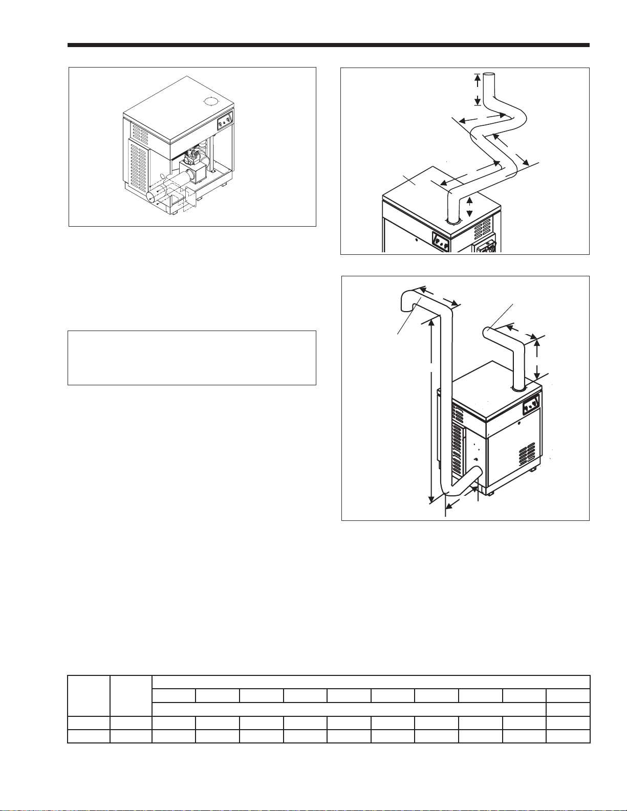
Total Length: 42'
Total Elbows: 5
EHE350
Figure 6. “One-pipe” installation.
Combustion
Air Pipe
7'
10'
2'
4'
8'
18'
Vent
Pipe
4'
5'
Combustion air piping may be single-wall
galvanized steel pipe or any of the above materials.
Comb.
Air Vent Total
Length 13' 9' 22'
Elbows 3 1 4
2G-3c. Size and Length of Combustion
Air and Vent Piping
Piping for combustion air and venting must
be large enough to avoid restriction of the heater
combustion system. Pipe diameter, number of elbows
2'
and length of pipe determine how much it restricts
fl ow to or from the heater. Also, a large heater requires
Figure 7. “Two-pipe” installation.
larger pipe than a small heater because it operates with
higher fl ow of combustion air and exhaust products.
Table 3 specifi es the allowable length of piping for
various situations.
The following examples illustrate use of table 3:
1. A Model 350 heater is to be installed in a onepipe system (see Figure 6). The vent pipe is 42
feet long and has fi ve elbows. Per Table 3, 5"
piping must be used. (Only 16 feet of 4" vent
pipe would be allowable.)
Model Pipe Size
350 4” 61 (18.6) 50 (15.2) 39 (11.9) 27 (8.2) 16 (4.8) NA NA NA NA NA
Inches
(cm)
5” 225 (68.6) 211 (64.3) 197 (60) 184 (56) 170 (51.8) 157 (47.8) 143 (43.5) 130 (39.6) 116 (35.4) 103 (31.4)
123456789
Total Length of Pipe - Feet (m)
Number of Elbows
10
Table 3. Maximum Combined Length of Combustion Air and Vent Piping in Feet.

Page 6
2G-3d. Combustion Air and Vent Pipe
Installation
The Hi-E
2 must be vented to the outdoors.
It must not be vented in common with any other
appliance, even if that appliance is of the condensing
type. Common venting can result in severe corrosion
of the Hi-E2 or of the other appliances or their venting,
or escape of combustion product gases through
such appliances or vents. Do not vent the Hi-E
2 to a
fi replace chimney or building chase.
Combustion air ducting, when provided, must
not be shared with any other appliance or with another
Hi-E
2. Doing so may result in fl ow of air through the
other appliances instead of directly from the outdoors.
The combustion air intake and vent outlet must
be located exterior to the building and in the same
pressure zone - i.e. both through the roof or both
through a side wall. The vent terminal must be located
in accordance with local codes, as applicable, and in
accordance with the following:
1. Locate the vent terminal so that it will not be
damaged by pedestrians and other traffi c, and so
that the discharge is not offensive. The National
Fuel Gas Code requires a through-wall vent
terminal be at least 7 feet (2.13 m) above grade if
located at a public walkway.
2. Locate the vent terminal so the vent exhaust does
not settle on building surfaces and other nearby
objects. Vent products may corrode such surfaces
or objects.
PVC Adapter
when required
4" PVC Pipe
Clamping Connector
with Neoprene,
Nitrile or EPDM
Sleeve
(R0444900)
Hi-E2 Vent Collar
3. Locate the vent terminal at a suffi cient horizontal
distance from any gas or electric metering,
regulating or relief equipment. In the United
States, this distance must be at least 4 feet
(1.21m). In Canada, it must be at least 10 feet
(3.04m).
4. Locate the vent terminal at a suffi cient horizontal
distance from any building opening. Take special
care to assure that combustion products do
not enter a building through windows, doors,
ventilation inlets, etc. In the United States, this
distance must be at least 4 feet (1.21 m). In
Canada, it must be at least 10 feet (3.04 m).
As shown in Figures 9 and 10, the combustion air
intake and the vent outlet must be installed no closer
together than 18" (45.7cm) and no farther apart than
60" (1.5m). The combustion air inlet opening must
face downward to prevent entry of rain or snow. The
vent outlet must discharge away from the combustion
air inlet - normally in a horizontal direction when on
a wall and vertically upward when on a roof. Both
should terminate at least 12" (30.5cm) above the snow
accumulation level. In locations with freezing climate,
extension of the vent pipe outside of the building
should be minimized. The insect screens provided
Figure 8. Indoor vent connection, Hi-E2 pool heater
Special insect screens installed
(see Figure 11)
Vent Exhaust
Combustion
Air Pipe
7" min.
maximum snow level
Figure 9. Vent and combustion air terminals at exterior
wall.
Pipe
18" min.
60" max
12" min.to
6" min.
Grade level
or normal
snow
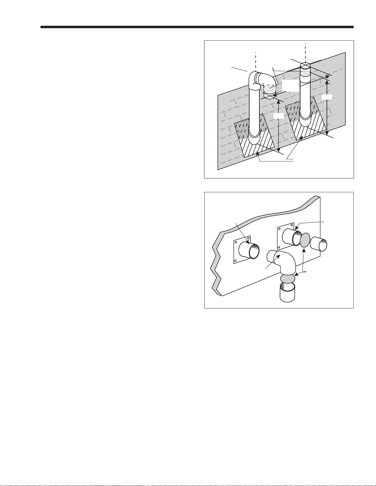
Hi-E2
Page 7
with the heater must be installed at the combustion air
and vent pipe openings as shown in Figure 11. Insect
screens are sized to fi t the inside of a 5" PVC pipe
fi tting. Trim them as necessary for smaller pipe sizes.
Connect the vent pipe to the heater vent collar
with an air-tight corrosion-resistant clamp. The
connection must not allow leakage of combustion
products into the space but should be removable for
service (see Figure 8).
Connect the combustion air pipe to collar of the
air fi lter box. For this combustion air pipe only, sheet
metal pipe is most convenient and can be screwed
directly to the collar. Seal the joint with silicone sealer
or similar mastic material.
Install vent piping with a continuous rise of at
least 1/4" per foot (20 mm per meter) away from the
heater. This will assure that any condensate forming in
the vent pipe will fl ow back to the heater where it can
be disposed of properly.
Support vent piping with suitable hangers so
its weight does not bear on the heater or building
penetration and so that piping joints are not strained.
Support horizontal runs at intervals no greater than
6 feet (1.82 meters), and closer if necessary to avoid
sagging. Sagging can trap condensate water and block
the vent.
Both combustion air and vent piping joints must
be sealed. Metal combustion air pipe joints should
be fastened with screws and sealed with permanent
sealer or tape. Plastic vent pipe joints must be made
with solvent cement listed for such use. Joints in 29-
®
4C
stainless steel pipe must be sealed in accordance
with its listing. Connection of combustion air and
vent piping to the heater should be serviceable — i.e.
removable for heater service.
2G-3e. Room V entilation
The room a Hi-E
2 is installed in must be provided
with adequate ventilation. Like other gas-fi red
appliances, the Hi-E
2 releases heat to its environment,
and a room with no ventilation may become too warm.
In one-pipe installations, the normal (coderequired) provisions for combustion air also assure
reasonable ventilation of the room. In commercial
applications it is required that a two-pipe system be
used. If a two-pipe system is installed, ventilation must
be provided by other means, such as through grilles or
openings or with a small fan.
2G-3f. Inspection and Replacement of
Existing Vent System with New
Components
If the Hi-E
2 is being installed to replace an
existing pool heater, it is recommended that a new
appropriate venting system be installed with the new
heater. However, if an existing venting system must be
used, be sure to carefully inspect the venting system to
ensure that it is in good condition and continues to be
Vent
Exhaust
Insect Screens
Installed
Elbow
Combustion
Air Pipe
Figure 10. Vent and combustion air terminals at roof.
Combustion
Air Pipe
Figure 11. Installation of insect screens.
(See Fig. 10)
18" min.
60" max
A
Plumbing vent
roof boot
A=Maximum snow ac cu mu la tion level plus 12"
Elbow
Pipe
A
Vent
Exhaust
Pipe
Install special
insect screen
at end of pipe
inside coupling
or elbow. Cut
to size as nec es sary.
appropriate for the Hi-E2 heater. Replace any parts that
are not in good and serviceable condition with new
parts before completing the pool heater installation.
2H. Condensate Disposal
In a high-effi ciency combustion process,
combustion product gases are cooled so much that
liquid water is condensed. Flow of this “condensate”
can be quite high. When pool water is very cold, as
much as two or three gallons of condensate can be
produced in an hour. Condensate is mildly acidic.
Before treatment, its “pH” is typically in the 3.5 to 6.0
range.
Handling and disposal of condensate is not
complicated, but it must be done correctly to prevent
problems or complaints. A trap/neutralizer assembly is
provided with the heater to simplify installation. This
assembly is easily installed in the base of the heater.
Figure 12 illustrates its installation and the routing of
drain tubes.
Page 8
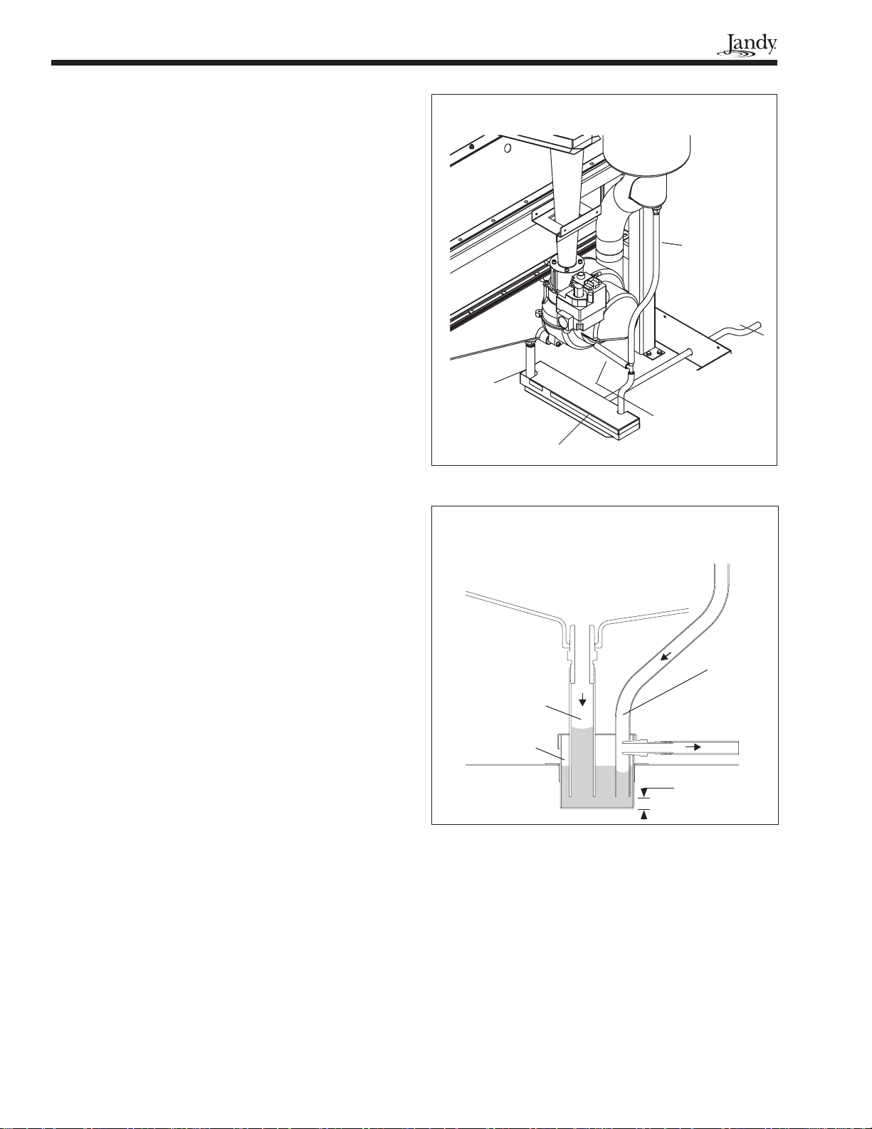
To install the condensate assembly, fi rst install
the short length of 5/8" I.D. tubing (Collector
Drain) on the barbed fi tting on the bottom of the
condensate collector. Then drop the condensate tray
into the opening in the base pan of the heater, bending
the 5/8" tubing as necessary to get the tube into the
tray. Readjust the 5/8" tubing so that its lower end
is 1/4" - 3/8" above the bottom of the tray. The tray
can be positioned with the outlet fi tting to the right,
as shown in Figure 12, or with the fi tting to the left,
depending on the direction required for condensate
disposal. Connect the piece of 1/2" I.D. tubing to this
outlet fi tting and route it out of the heater through the
hole in the side of the base panel. This tube carries
condensate to the drain. If this disposal tube is routed
to the left, remove the plug button from the hole on the
left side of the base panel and push it into the hole on
the right side.
Connect the remaining short piece of 3/8"
I.D. tubing to the barbed tee fi tting in the tubing
immediately in front of the blower. Position this tubing
so that its bottom end is 1/4"-3/8" above the bottom of
the condensate tray. This tube provides drainage for
the vent duct and blower.
A package of limestone gravel neutralizer
is provided with the condensate assembly. Place
this gravel in the tray after installing and properly
positioning all tubes. Be sure that a limestone pebble
does not plug any of the tubes. Place the cover on the
tray when this is done.
It is important that there be no sagging sections
of tubing to trap water. Drainage to the trap and out
of the trap to the drain must be assured by continuous
downward routing of these tubes. It may be necessary
to elevate the heater to provide downward routing. The
outlet of the disposal tube must be open to the air. PVC
pipe is recommended for long drain tubes.
If a gravity drain is not available, a condensate
pump must be provided in the fi eld. Suitable
condensate pumps are available commercially at air
conditioning equipment distributors.
Incorrect installation of the condensate assembly
or tubing can result in overfl ow or waterlogging of the
vent. In normal operation, water accumulates in the
tray at the level of the outlet fi tting, and this provides
a “water seal” which accommodates combustion
system pressures. Figure 13 illustrates the water seal.
Note that water is “pulled” up toward the condensate
collector pan and is pushed down slightly by the
vent/blower drain. If there is no water seal, air rushes
into the collector drain, preventing normal drainage of
condensate water, until vent drainage provides the seal
(see Section 2L, Start-Up and Adjustment).
The installer must be sure to take whatever
measures are necessary to prevent property damage by
condensate overfl ow. If the heater location is such that
Vent
Drain
To
Disposal
Collector
Drain
Blower
Drain
Trap/
Neutralizer
Figure 12. Condensate drainage components.
Condensate From
Vent/Blower Drains
Condensate
From
Collector
Drain
Water Level
Pushed Down
Water Level
Pulled Up
2"-3"
(50-75mm)
Trap
Figure 13. Condensate drain and trap.
Slightly
Overfl ow
To
Disposal
1/4" - 3/8"
(6-10mm)
this water can directly or indirectly damage a building,
furnishings or other property, an overfl ow pan or other
appropriate preventative measure should be provided.
2I. Gas Supply and Piping
Before installing gas piping, check the rating
plate on the heater to be sure that the heater is for use
with the correct (available) gas. Make sure that gas
supply pressure is adequate per the requirements in
Table 4.

Hi-E2
Supply Pressure Minimum Maximum
Natural Gas 5 inches WC
(125 mm WC)
LP Gas 11 inches WC
(280 mm WC)
Table 4. Gas Supply Pressure Requirements.
10.5 inches WC
(265 mm WC)
14 inches WC
(350 mm WC)
Gas piping must be large enough to provide the
required gas fl ow rate without excessive pres sure drop.
Table 5 specifi es pipe sizes which will limit pressure
drop to 0.5 In WC (125 Pa), based on the National
Fuel Gas Code, ANSI Z223.1/NFPA-54.
Model
350 1-1/4" 1-1/4" 1-1/2" 1" 1-1/4" 1-1/4"
Table 5. Required Gas Pipe Size.
Natural Gas LP Gas
0-50'
(0-15m)
50-100'
(15-30m)
100-200'
(30-60m)
0-80'
(0-15m)
50-100'
(15-30m)
100-200'
(30-60m)
Support gas piping properly so its weight
does not bear on the heater. Install a drip leg, a nonrestrictive shutoff valve and a union on the gas supply
line outside of the heater (see Figure 14).
Before operating the heater, test the gas supply
system, including all connections, for leaks using a
soap solution. Do not use a fl ame or any ignition
source for leak detection. Dis con nect the heater and its
individual gas shutoff valve during pressure testing if
the test pressure is higher than 1/2 psig (3.34 kPa). If
the pres sure is 1/2 psig (3.45 kPa) or lower, close the
manual valve on the heater gas control during testing.
When the heater is started, check the supply
pressure to verify that it is adequate during heater
operation. Undersize piping, a restrictive fi tting or an
undersize gas meter can cause low operating pressure.
High Elevation
To assure good combustion and general
op er a tion, gas appliances are normally de-rated when
installed at high elevation. This is not necessary
with the Hi-E
2 because it has a special venturi-type
combustion system which self-com pen sates for
changes in barometric pressure. Air fl ow through the
venturi pulls the correct fl ow of gas into the burner
regardless of air density. Good quality combustion and
high effi ciency are assured without special adjustment
or changes to the heater.
2J. Electric Wiring
WARNING
ELECTRICAL SHOCK HAZARD. This heater
contains wiring that carries high voltage. Contact with these wires may result in severe injury
or death.
Page 9
From
Supply
To
Heater
Figure 14. Gas piping at heater.
CAUTION
Label all wires prior to disconnection when
servicing controls. Wiring errors can cause
improper and dangerous operation.
Verify proper operation after servicing.
2J-1. Electrical Power
Electrical wiring must be in accordance with the
latest edition of the National Electric Code (NEC),
ANSI/National Fire Protection Association (NFPA) 70,
unless local code requirements indicate otherwise; and
in Canada with latest edition of CSA C22.1 Canadian
Electrical Code.
The Hi-E
2 requires electrical power from a 115V,
60 Hz source. Wiring connections must be made
exactly as shown in the wiring diagram (see Figure
16). Grounding must be provided as required by the
prevailing electrical code.
Connect wiring inside the junction box , which is
on the right side of the heater and is accessible through
the door opening. Line voltage con nec tions must be
made within this box. A labeled green grounding screw
is provided in the junction box for a ground ing wire
(see Figure 15).
ATTACH GROUND-
ING WIRE TO
GREEN GROUND-
ING SCREW
Figure 15. Field wiring connections.
 Loading...