

Jandy EE2000T-263, EE-Ti Series, EE1500T, EE2000T, EE2500T Installation & Operation Manual
...
Installation and Operation Data
Installation and
Op er a tion Man u al
Jandy® Heat Pumps
Model EE-Ti
English
Français
Español
WARNING
FOR YOUR SAFETY - This product must be installed by a licensed HVAC technician certifi ed
in heat pump repair and maintenance by the jurisdiction in which the product will be installed
where such state or local requirements exists. The technician must possess and comply with all
certifi cations and regulations regarding the purchasing, handling, transportation and reclamation of
R410A refrigerant. In the event no such state or local requirement exists, the installer or maintainer
must be a professional with suffi cient experience in pool equipment installation and maintenance
so that all of the instructions in this manual can be followed exactly. Before installing this product,
read and follow all warning notices and instructions that accompany this product. Failure to
follow warning notices and instructions may result in property damage, personal injury, or death.
Improper installation and/or operation can create an electrical hazard which can cause serious
injury, property damage, or death. Improper installation and/or operation will void the warranty.
H0335800 RevD


Jandy Heat Pump Models EE-Ti Installation and Maintenance Manual
Table of Contents
Page 1
Section 1. General Information ..................3
1.1 Introduction ......................................................... 3
1.2 Consumer Information and Safety ......................3
1.2.1 Spa/Hot Tub Safety Rules ............................3
1.2.2 Swimming Pool Energy Saving Tips ............4
1.3 Warranty ............................................................. 4
1.4 Codes and Standards .........................................4
1.5 Technical Assistance ........................................... 5
1.6 Materials Needed For Installation .......................5
1.6.1 Materials for All Installations ........................ 5
1.6.2 Recommended Materials for Installations .... 5
1.7 Specifications ...................................................... 5
1.7.1 General Specifications ................................. 5
1.7.2 Dimensions .................................................. 5
1.7.3 Technical Specifications ...............................5
Section 2. Installation Instructions ............5
2.1 General Information ............................................ 5
2.2 Location Requirements ....................................... 5
2.2.1 Introduction .................................................. 5
2.2.2 Clearances ...................................................7
2.2.3 Equipment Pad ............................................ 8
2.2.4 Condensation and Drainage ........................ 8
2.2.5 Lawn Sprinklers ........................................... 8
2.2.6 Roof Run-off ................................................. 8
2.2.7 Installation of Anchor Clamps ...................... 8
4.5.2.2 Install the Remote TSTAT .................... 17
4.5.2.3 Configure the Control Panel ................18
4.5.3 Four-Wire Connection to AquaLink
485 Communication ................................... 18
4.5.4 Connection to a Secondary User Interface 19
®
RS
Section 5. Operation ..................................19
5.1 Initial Start-up Precautions ................................ 19
5.2 Operating the Controller ...................................19
5.2.1 Off Mode .................................................... 19
5.2.2 Pool Mode - (Normal Heat) ........................ 19
5.2.3 Pool Mode - (Optional Maintain Heat) ........ 20
5.2.4 Spa Mode - (Normal Heat) ......................... 20
5.2.5 Spa Mode - (Optional Maintain Heat) ........20
5.3 Operating Features of Hybrid Units with
Optional Chiller ................................................. 20
5.3.1 Pool Mode - (Normal Chill) ......................... 20
5.3.2 Pool Mode - (Optional Maintain Chill) ........ 20
5.3.3 Spa Mode - (Optional Maintain Chill) ......... 21
5.4 User Setup Options ..........................................21
5.4.1 Language Setup ......................................... 21
5.4.2 Temperature Scale Setup ..........................21
5.4.3 Spa Timer Setup ........................................ 21
5.4.4 Display Light Setup .................................... 21
5.5 Set Point Lockout .............................................. 22
5.6 Water Pressure Switch Adjustment ................... 22
Section 3. Water Connections ...................9
3.1 Plumbing Layout ................................................9
3.2 Water Connections at Heat Pump ...................... 9
3.3 Check Valve Installation ...................................... 9
3.4 Automatic Flow Control Valve ...........................10
3.5 Multiple Unit Installation .................................... 10
3.5.1 Heat Pump and Heater Combination ......... 10
3.5.2 Multiple Heat Pump Connections ............... 10
Section 4. Electrical Connections ............10
4.1 General Information .......................................... 10
4.2 Main Power ....................................................... 16
4.3 Bonding ............................................................. 16
4.4 Pump Connection (Maintain Temp Feature) ..... 16
4.5 Optional Remote Controls ................................17
4.5.1 Connection to a Remote Pool-Off-Spa
Selector (3-Wire Connection) ..................... 17
4.5.1.1 Install the Remote Pool-Off-Spa
Selector ................................................ 17
4.5.1.2 Configure the Control Panel ................17
4.5.2 Two-Wire Connection to an AquaLink® RS
or TSTAT .................................................... 17
4.5.2.1 Configure the AquaLink RS Control
System ................................................. 17
Section 6. General Maintenance ..............23
6.1 Water Chemistry ............................................... 23
6.2 Winterizing ........................................................ 23
6.3 Spring Start-Up ................................................. 24
6.4 Inspection and Service .....................................24
6.4.1 Owner Inspection ....................................... 24
6.4.2 Professional Inspection .............................. 24
Section 7. Professional Maintenance
and Service ..............................25
7.1 Heat Pump Design ............................................ 25
7.2 Heat Pump Components and Operation ........... 25
Section 8. Troubleshooting ......................26
8.1 Troubleshooting Guide...................................... 26
8.2 Diagnostics ....................................................... 27
Section 9. Replacement Parts ..................28
9.1 Ordering Information ......................................... 28
9.2 Jandy EE-Ti Heat Pumps Parts List ..................28
9.3 Jandy EE-Ti Heat Pumps Exploded View ........ 29

Page 2
Jandy Heat Pump Models EE-Ti Installation and Maintenance Manual
Figures and Tables
Figure 1. Jandy EE-Ti Heat Pumps Dimensions .......7
Figure 2. Anchor Clamp Positions .............................9
Figure 3. Anchor Clamp Installation ..........................9
Figure 4. Standard Plumbing Layout ....................... 11
Figure 5. Plumbing For Heating System
Combinations ........................................... 11
Figure 6. Two (2) Heat Pump Plumbing Layout ......12
Figure 7. Four (4) Heat Pump Plumbing Layout .....12
Figure 8. EE-Ti Single-Phase Electrical Supply
Wiring Diagram ........................................13
Figure 9. EE-Ti 3-Phase Electrical Supply Wiring
Diagram ...................................................14
Figure 10. Example of “MAINTAIN TEMP” Wiring to
the Time Clock .........................................15
Figure 11. EE-Ti Heat Pump Front View ...................15
Figure 12a. Remote Pool-Off-Spa Connection
(3-Wire Connection) .................................16
Figure 12b. AquaLink RS or Remote TSTAT
Connection (2-Wire Connection) ..............16
Figure 13. AquaLink RS to EE-Ti Heat Pump ...........17
Figure 14. EE-Ti Heat Pump Connection to Power
Center ......................................................18
Figure 15. Main Control Panel ..................................20
Figure 16. Winterizing the EE-Ti Heat Pump ............23
Figure 17. Heat Pump Operation Overview ..............25
Figure 18. Jandy EE-Ti Heat Pumps Exploded
View (EE2500 Shown) .............................29
Table 1. EE-Ti Heat Pump Technical
Specifications ............................................. 6
Table 2. Heat Pump Clearances ..............................7
Table 3. Optimal Water Chemistry Ranges ............23
Table 4. Heat Pump Troubleshouting Guide ..........26
Table 5. Heat Pump Diagnostics ...........................27

Jandy Heat Pump Models EE-Ti Installation and Maintenance Manual
Page 3
Section 1. General Information
1.1 Introduction
This manual provides installation and operation
instructions for the Jandy EE-Ti models of heat pumps.
Read these installation and operation instructions
completely before proceeding with the installation.
Consult Zodiac Pool Systems, Inc. (“Zodiac”) with any
questions regarding this equipment. To obtain additional
copies of this manual contact us at 800-822-7933. The
following is the address information for:
Zodiac Pool Systems, Inc.
6000 Condor Drive
Moorpark, CA 93021 USA
The EE-Ti heat pump gets electrical power from
an external source and provides a dual digital thermostat
control system for pool/spa combinations or preheat
convenience.
This heat pump is specifically designed for heating
fresh water swimming pools and spas. Do not use it
as a general service heater. Consult your dealer for the
appropriate Jandy products for these applications.
NOTE “Fresh water swimming pools and spas” include
systems that utilize saltwater chlorine generator
units, such as the Jandy AquaPure® Electronic
Chlorine Generator. Please ensure that the salt
content of the pool/spa does not exceed
4500 ppm and water fl ow rate is within
30-125 gpm (110-125 lpm).
ATTENTION
Installation and service must be performed by
a qualifi ed installer or service agency.
To the Installer: After installation, these
instructions must be given to
the homeowner or left on or
near the heat pump.
1.2.1 Spa/Hot Tub Safety Rules
WARNING
The U.S. Consumer Product Safety Commission
warns that elevated water temperature can
be hazardous. Consult heater operation and
installation instructions for water temperature
guidelines before setting temperature.
AVERTISSEMENT
La Commission U.S. de Sécurité des Produits
pour les Consommateurs indique que des
températures de l’eau élevées peuvent être
dangereuses. Voir la notice d’installation
et de fonctionnement pour le réglage de la
température.
AVISO
La Comisión de Seguridad de Productos para
el Consumidor de los Estados Unidos, advierte
que una temperatura elevada del agua puede
ser peligrosa. Consulte las instrucciones de
instalación y funcionamiento del calentador
para seguir las directrices relacionadas con la
temperatura del agua antes de proceder a fi jar
la temperatura.
WARNING
The following “Safety Rules for Hot Tubs,”
recommended by the U.S. Consumer Product
Safety Commission, should be observed when
using the spa.
AVERTISSEMENT
Les Règlements suivants pour Cuves
Thermales, tel que recommandés par la
Commission U.S. de Sécurité des Produits pour
les Consommateurs, devraient être respectés
lors de l’utilisation du spa.
To the User: This manual contains
important information that
will help you in operating and
maintaining this heat pump.
Please retain it for future
reference.
1.2 Consumer Information and Safety
The EE-Ti series of heat pumps are designed
and manufactured to provide many years of safe
and reliable service when installed, operated and
maintained according to the information in this manual
and the installation codes referred to in later sections.
Throughout the manual, safety warnings and cautions
are identified by the “
comply with all of the warnings and cautions.
“ symbol. Be sure to read and
AVISO
Al utilizar el spa, deberán observarse, las
siguientes “Reglas de Seguridad para Baños
Calientes” recomendadas por la Comisión de
Seguridad de Productos para el Consumidor de
los Estados Unidos.
1. Spa or hot tub water temperature should never
exceed 104°F (40°C). One hundred degrees
Fahrenheit (100°F [38°C]) is considered safe for a
healthy adult. Special caution is recommended for
young children.
2. The drinking of alcoholic beverages before or
during spa or hot tub use can cause drowsiness
which could lead to unconsciousness, and
subsequently result in drowning.

Page 4
Jandy Heat Pump Models EE-Ti Installation and Maintenance Manual
3. Pregnant women take note! Soaking in water
above 102°F (38.5°C) can cause fetal damage
during the fi rst three (3) months of pregnancy
(which could result in the birth of a brain-damaged
or deformed child). If pregnant women are going
to use a spa or hot tub, they should make sure
the water temperature is below 100°F (38°C)
maximum.
4. The water temperature should always be checked
with an accurate thermometer before entering a
spa or hot tub. Temperature controls may vary by
as much as 1F° (1°C).
5. Persons with a medical history of heart disease,
diabetes, circulatory or blood pressure problems
should consult their physician before using a hot
tub or spa.
6. Persons taking any medication which induces
drowsiness (e.g., tranquilizers, antihistamines, or
anticoagulants) should not use spas or hot tubs.
7. Prolonged immersion in hot water can induce
hyperthermia.
Hyperthermia occurs when the internal body
temperature reaches a level several degrees above the
normal body temperature of 98.6°F (37°C). Symptoms
include dizziness, fainting, drowsiness, lethargy, and an
increase in the internal body temperature. The effects of
hyperthermia include:
• Lack of awareness of impending hazard
• Failure to perceive heat
• Failure to recognize need to leave spa
• Physical inability to leave spa
• Fetal damage in pregnant women
• Unconsciousness resulting in a danger of
drowning
1.2.2 Swimming Pool Energy Saving Tips
It is important to note that a heat pump will not
heat a pool as fast as a large gas or electric pool heater.
If the pool water is allowed to cool significantly, it may
take several days to return to the desired swimming
temperature. For weekend use, it is more economical
to maintain the pool water temperature at or near your
desired swimming temperature. If you do not plan to
use your pool for a prolonged period, then you might
choose to turn the heat pump completely off or decrease
the temperature setting of the control several degrees to
minimize energy consumption.
Zodiac offers the following recommendations to
help conserve energy and minimize the cost of operating
your heat pump without sacrificing comfort.
1. The American Red Cross recommends a maximum
water temperature of 78°F (25°C). Use an accurate
pool thermometer. A difference of 4°F (2°C),
between 78°F and 82°F (26°C and 28°C), will
signifi cantly increase energy consumption.
2. Carefully monitor the water temperature of your
pool in the summertime. You can reduce heat
pump usage due to warmer air temperatures.
3. During the winter or when on vacation for longer
than a week, turn off the heat pump.
4. Find the proper setting on the heat pump
temperature control and use the Set Point Lockout
or lock the cover on the heat pump controller to
discourage further adjustments.
5. Set the pump time clock to start the pump no
earlier than 6:00 AM during the pool heating
season. This is the time when nightly heat loss
balances.
6. Where possible, shelter the pool from prevailing
winds with well-trimmed hedges or other
landscaping, cabanas, or fencing.
7. Always use a pool cover when practical. Besides
providing a valuable safety feature, a pool cover
will reduce heat loss, conserve chemicals, and
reduce the load on fi lter systems.
1.3 Warranty
The EE-Ti heat pump is sold with a limited factory
warranty. Details are specified on the back cover of this
manual.
Make all warranty claims to your Jandy dealer or
directly to Zodiac. Claims must include the heat pump
serial number and model (this information can be found
on the rating plate), installation date, and name of the
installer. Shipping costs are not included in the warranty
coverage.
The warranty does not cover damage caused by
improper assembly, installation, operation, winterizing,
field modification, or failure to earth bond and
properly ground the unit. Any changes to the heat
pump, evaporator, heat exchanger, wiring, or improper
installation may void the warranty.
1.4 Codes and Standards
The EE-Ti heat pump is listed by ETL as
complying with the latest edition of the “UL Standard
for Safety for Heating and Cooling Equipment”, UL
1995 and CSA C22.2 No. 236.
All Jandy heat pumps must be installed in
accordance with the local building and installation
codes as per the utility or authority having jurisdiction.
All local codes take precedence over national codes. In
the absence of local codes, refer to the latest edition of
the National Electrical Code (NEC) in the United States
and the Canadian Electrical Code (CEC) in Canada for
installation.

Jandy Heat Pump Models EE-Ti Installation and Maintenance Manual
Page 5
1.5 Technical Assistance
Consult the Zodiac technical support department
or your local Jandy dealer with any questions or
problems involving the specifications, installation, and
operation of your Jandy equipment. An experienced
technical support staff is ready to assist you in assuring
the proper performance and application of Jandy
products. For technical support call the Zodiac technical
support department at (800) 822-7933.
1.6 Materials Needed For Installation
1.6.1 Materials for All Installations
The following items are needed and are to be
supplied by the installer for all heat pump installations:
1. Plumbing connections (2”).
2. Level surface for proper drainage.
3. Suitable electrical supply line. See rating plate on
unit for electrical specifi cations. A junction box is
not needed at the heat pump; connections are made
inside of the heat pump electrical compartment.
Conduit may be attached directly to the heat pump
jacket.
NOTE Flex conduit is recommended for connecting
the electrical supply wires to the heat pump so
that the front panel may be removed easily for
servicing.
4. Electric cutout switch that will interrupt all power
to the unit. This switch must be within line of sight
of the heat pump.
5. Watertight conduit to run the electrical supply line.
Electrical Supply
Voltage Requirements
1-Phase
3-Phase
Maximum Working Refrigerant
Pressure 585 PSI
230 VAC 60Hz
230 VAC 60Hz
(Model dependent)
1.7.2 Dimensions
See Figure 1 for heat pump’s dimensions and for
dimensions to critical connections.
1.7.3 Technical Specifi cations
See Table 1 for the EE-Ti Heat Pump Technical
specifications.
Section 2. Installation Instructions
2.1 General Information
Install the Jandy heat pumps in accordance
with the procedures in this manual, local codes and
ordinances, and in accordance with the latest edition of
the appropriate national code. (See Section 1.4, “Codes
and Standards”.) Correct installation is required to
assure safe operation. The requirements for Jandy heat
pumps include the following:
1. Field assembly (if required).
2. Appropriate site location and clearances.
3. Suffi cient air ventilation.
4. Proper electrical wiring.
5. Adequate water fl ow.
1.6.2 Recommended Materials for
Installations
Zodiac recommends installing isolation valves
on the inlet and outlet water connections for ease of
serviceability.
1.7 Specifi cations
1.7.1 General Specifi cations
Suitable for indoor and outdoor use. Clearances
shown in Table 2 must be adhered to.
Water Pipe/Heater Connection
Plastic 2” PVC (Unions
included)
Flow Rate
Maximum
Optimum
Minimum
Maximum Working Water
Pressure 75 psi
125 gpm (475 lpm)
60 gpm (230 lpm)
30 gpm (110 lpm)
This manual provides the information needed to
meet these requirements. Review all application and
installation procedures completely before continuing the
installation.
2.2 Location Requirements
2.2.1 Introduction
NOTE Indoor installations require special
considerations for condensate drainage and
venting the cold air produced by the heat
pump. Contact the Zodiac technical support
department at (800) 822-7933.
CAUTION
When pool equipment is located below the pool
surface, a leak from any component can cause
large scale water loss or fl ooding. Zodiac cannot
be responsible for such water loss or fl ooding or
resulting damage.
Page 6
Jandy Heat Pump Models EE-Ti Installation and Maintenance Manual
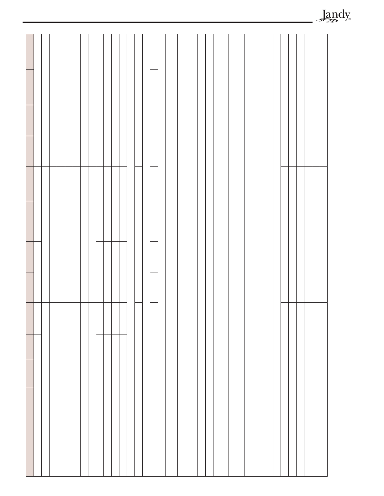
Table 1. EE-Ti Heat Pump Technical Specifi cations
230/60/1 230/60/1 230/60/3 230/60/1 230/60/3 230/60/1 230/60/3
7.2 6.4 6.3 6.1
3.3 kW 5.1 kW 5.6 kW 6.7 kW
80,000 BTUs 112,000 BTUs 120,000 BTUs 140,000 BTUs
6.0 5.75 5.8 5.8
67,000 BTUs 102,000 BTUs 111,000 BTUs 132,000 BTUs
50,000 BTUs 72,000 BTUs 76,000 BTUs 90,000 BTUs
4.1 4.1 4.0 4.0
21A 26.9A 19.2A 26.9A 23A 26.9A 26.9
115A 145A 170A 145A 160A 145A 190A
28A 37A 27A 37A 32A 37A 36A
45A 60A 45A 60A 50A 60A
Titanium
40K Scroll 61K Scroll 68K Scroll 83K Scroll
ABS
58 PSI (reset to 127 PSI)
585 PSI (reset to 445 PSI)
64 Oz, R410A 78 Oz, R410A 90 Oz, R410A 100 Oz, R410A 90 Oz, R410A 100 Oz, R410A 114 Oz, R410A 124 Oz, R410A 114 Oz, R410A 124 Oz, R410A
30 GPM
35 PSI (reset to 74 PSI)
60 GPM
5 feet below pool level
11 feet above pool level
30 GPM
125 GPM
2”
58.9 dBa
Adjustable between 1°F to 5°F
2060 CFM 4120 CFM
225 LBS 325 LBS
NA 71,000 BTUs 54,000 BTUs
NA 6.9 kW 7.2 kW
NA 3.01 2.22
NA 87,000 BTUs 60,000 BTUs
NA 7.4 kW 7.3 kW
NA 3.46 2.4
MODEL EE1500T EE2000T EE2000T--263 EE2500T EE2500T-R EE2500T--263 EE2500T-R263 EE3000T EE3000T-R EE3000T--263 EE3000T-R263
VOLTAGE
OUTPUT*
INPUT*
COP*
OUTPUT, STANDARD RATING CONDITIONS**
COP, STANDARD RATING CONDITIONS**
OUTPUT, LOW AMBIENT**
COP, LOW AMBIENT**
RLA (RUNNING LOAD AMPS)
LRA (LOCKED ROTOR AMPS)
MINIMUM CIRCUIT AMPACITY
MAX OVER CURRENT PROTECTION***
HEAT EXCHANGER
COMPRESSOR
CABINET
REFRIGERANT
REFRIGERANT HIGH PRESSURE ALARM
REFRIGERANT LOW PRESSURE ALARM -
HEATING UNITS
REFRIGERANT LOW PRESSURE ALARM -
REVERSE UNITS
LOW WATER FLOW ALARM
MAXIMUM HEIGHT BELOW WATER LEVEL
MINIMUM HEIGHT ABOVE WATER LEVEL
OPTIMAL WATER FLOW
MINIMUM WATER FLOW
MAXIMUM WATER FLOW
AIR FLOW
WATER TEMPERATURE DIFFERENTIAL
(DELTA T)
UNION SIZE
WEIGHT
SOUND PRESSURE PER ISO 3471
OUTPUT - Chiller****
INPUT - Chiller****
COP - Chiller****
OUTPUT - Chiller*****
INPUT - Chiller*****
COP - Chiller*****
** Rated in accordance with AHRI Standard 1160 (I-P)
* Test Conditions: 80˚ F Air, 80% RH, 80˚ F Water, Outside the scope of AHRI Standard 1160 (I-P)
*** Max Over Current Protection refers to the maximum breaker size allowed. If this value is not a standard breaker size, use the next smallest standard size breaker.
The breaker size must not be smaller than the Minimum Circuit Ampacity value.
**** Test Conditions: Chiller mode, 96° F Air, 50% RH, 80° F Water, Ouside the scope of AHRI Standard 1160 (I-P)
***** Test Conditions: Chiller mode, 96° F Air, 50% RH, 95° F Water, Ouside the scope of AHRI Standard 1160 (I-P)

Jandy Heat Pump Models EE-Ti Installation and Maintenance Manual
Figure 1. Jandy EE-Ti Heat Pumps Dimensions
MODEL SIZE DIMENSIONS
ABCDEFG
EE1500 26” 31” 7.25” 25” 21” 12” 35”
EE2000 33” 38” 10.75” 25” 22” 14” 41”
EE2500 33” 38” 10.75” 25” 22” 14” 41”
EE3000 33” 42” 10.75” 30” 26” 17”
A
B
3.5”
C
11. 5”
Page 7
41”
G
D
E
F
ATTENTION
Lorsque l’équipement d’une piscine est situé
sous la surface de l’eau, une fuite provenant de
n’importe quel élément peut causer une perte
d’eau importante ou une inondation. Zodiac
Pool Systems, Inc. n’est pas responsable des
pertes d’eau, des inondations ou des avaries
causées par une installation ou un entretien
inadéquat.
PRECAUCIÓN
Cuando el equipo de la piscina esté situado
por debajo de la superfi cie de la piscina, la
fuga de cualquiera de los componentes, podría
ocasionar la pérdida de grandes cantidades
de agua o inundación. Zodiac Pool Systems,
Inc. no se responsabilizará de dichas pérdidas
de agua o inundaciones, ni de los daños que
puedan derivarse de las mismas.
Avoid placing the heat pump in locations where
it can cause damage by water or condensate leakage. If
this is not possible, provide a suitable drain pan to catch
and divert any leakage.
All criteria given in the following sections reflect
minimum clearances. However, each installation must
also be evaluated, taking into account the prevailing
local conditions such as proximity and height of walls,
and proximity to public access areas.
2.2.2 Clearances
The heat pump must be placed to provide
clearances on all sides for maintenance and inspection.
See Table 2.
Table 2. Heat Pump Clearances
Side of
Heat
pump
Front 6 15 24 60
Rear 6 15 12 30
Left 6 15 12 30
Right 6 15 12 30
Top 60 150 60 150
NOTE: Clearances listed inTable 2 are manufacturer’s tested values.
These are given as minimum values.Where local and national codes
apply, and values are different than those listed in Table 2, use the
greater value to ensure safe and proper operation.
Minimum Clearances for
Operation
Inches Centimeters Inches Centimeters
Recommended Clearances
for Serviceability
Access in front of the heat pump of 24” (60 cm)
provides adequate room for serviceability.
If the heat pump is to be installed in a garage
or under a vertical overhang, the unit must have a
minimum of 5 feet
(1.5 meters)
clearance from the top
of the heat pump.
In the U.S., the heat pump must be installed at least
5 feet (1.5 meters) from the inside wall of the pool or spa
unless the heat pump is separated from the pool or spa by a 5
foot (1.5 meters) high solid fence or other permanent barrier.
Aux Etats-Unis, ce chauffe-piscine doit être
installé á au moins 5 pieds (1,5 m) de la paroi
interne de la piscine à moins d’être isolé de la
piscine par une clôture, un mur ou autre barrière
permanente.
En Estados Unidos, esta bomba de calor
deberá instalarse a una distancia de al menos 5 pies
(1,5 metros) de la pared interior de la piscina; a
menos que la bomba de calentar esté separada de
la piscina mediante una valla sólida de 5 pies (1,5
metros) de altura u otra barrera permanente.

Page 8
Jandy Heat Pump Models EE-Ti Installation and Maintenance Manual
In Canadian installations, the minimum distance to
be maintained from the inside wall of the pool or spa is
3 meters (approx. 10 feet).
Pour les installations canadiennes, la distance
minimale à maintenir du mur intérieur de la piscine
ou du spa est de 3 mètres (approximativement 10
pieds).
2.2.3 Equipment Pad
Place the heat pump on a flat slightly pitched
surface, such as a concrete or fabricated slab (pad). This
allows proper drainage of condensation and rain water
from the base of the unit. If possible, the pad should be
placed at the same level or slightly higher than the filter
system equipment pad.
NOTE Ensure that the pad is pitched not more than ¼
inch per foot cm per toward the compressor end
(front) of the heat pump. Pitch slab from back to
front ¼ inch per foot maximum and level from
side to side.
2.2.4 Condensation and Drainage
Condensation will occur from the evaporator coil
while the unit is running and drain at a steady rate,
usually 3 to 5 gallons (11.4 to 18.9 liters) per hour,
depending upon ambient air temperature and humidity.
The more humid the ambient conditions, the more
condensation will be produced. The bottom of the unit
acts as a tray to catch rainwater and condensation. Keep
the drain hole located on the right side of the base of the
unit clear of debris.
If the heat pump is installed indoors, means of
condensate disposal must be provided. The drain hole
in the base of the heat pump is tapped to fit an optional
3/4” diameter barbed adapter, Jandy p/n R3004100 (see
Section 9, “Replacement Parts”). If using the barbed
adapter, connect a length of 3/4” tubing (5’ is included
in Jandy p/n R3004100) to the adapter, then route it
into a drain or outside the building to dispose of the
condensate. It is important to remember that no part of
the tubing or hose may be above the level of the drain
hole in the base of the heat pump.
2.2.5 Lawn Sprinklers
Keep lawn sprinkler heads from spraying on the
heat pump to prevent corrosion and damage. Use a
deflector if needed.
2.2.6 Roof Run-off
Make sure the heat pump is not located where
large amounts of water may run-off from a roof into
the unit. Sharp sloping roofs without gutters will allow
massive amounts of rain water, mixed with debris from
the roof to be forced through the unit. A gutter or down
spout may be needed to protect the heat pump.
2.2.7 Installation of Anchor Clamps
In Florida, building codes require that the heat
pump be anchored to the equipment pad or platform
to withstand high wind pressures created during
hurricanes. Other jurisdictions may have similar
requirements. Please check your local codes for further
details.
This heat pump is provided with anchor clamps
designed to hold the unit to the equipment pad in high
wind conditions. Installation of the anchor clamps is
recommended in all installations and are required in
Florida (reference Florida Building Code, Mechanical
Section 301.13).
To install the anchor clamps:
1. Be sure that the heat pump is in its permanent
location on the equipment pad.
2. Remove the anchor clamps from the installation
and instruction package.
NOTE: Bolts and bolt anchors are not included with
the heat pump. Zodiac recommends that a
1/4” x 1½” long stainless steel Tapcon® type
concrete screw is used to mount the clamp
to the equipment pad. The Tapcon type
concrete screw meets Florida building code
requirements.
3. Place the clamps at the base of the heat pump in
the locations indicated in Figure 2.
NOTE: To install the brackets on the front of the heat
pump, the front cover must be loosened enough
in order to place the bracket over the lip of the
base. Be sure to re-tighten the front jacket
panel to the heat pump.
4. Fit the hook of each clamp over the lip on the
base panel of the heat pump. The hook should
fi t between the lip of the base panel and the
evaporator coil guard (see Figure 3).
5. Mark the position of the hole in each clamp on the
equipment pad.
6. Drill a hole in the cement using a masonry drill
bit, with a diameter as determined by the concrete
anchor, at each of the marks on the equipment pad.
The hole should be approximately 1-1/2” deep.
7. Insert a bolt anchor into each of the holes. Be sure
the anchors are set completely into the holes.
8. Position the anchor clamps so that the holes in the
clamps are over the bolt anchors. Be sure that the
clamp hooks are over the lip of the heat pump base
(see Figure 3).
9. Insert an anchor bolt through each clamp into the
anchor and tighten to secure the clamp and heat
pump to the equipment pad.

Jandy Heat Pump Models EE-Ti Installation and Maintenance Manual
Page 9
Attach anchor
brackets to base
of heat pump
where indicated
by the arrows.
Figure 2. Anchor Clamp Positions
Section 3. Water Connections
3.1 Plumbing Layout
Figure 4 illustrates the standard plumbing layout
with a single heat pump unit. Following the diagram
from right to left, the plumbing sequence is as follows:
Pool > Pool Pump > Filter > Heat Pump > Check
Valve > Chemical Loop > Chlorinator > Pool
NOTE For normal installations, do not install a shutoff
valve or any kind of variable restriction in the
water piping between the heat pump outlet and
the pool/spa.
Arrangement of pool system components other
than as illustrated in the preceding and following
diagrams can affect the operation of the heat pump’s
water pressure switch. Location of the heat pump
above or below the pool water surface can also affect
operation of the switch. In general, the pressure switch
can be adjusted to accommodate this effect if the heat
pump water connections are no more than 5 feet below
the pool water surface or no more than 11 feet above it.
See instructions for pressure switch adjustment (Section
5.6) in the heat pump start-up section of this manual for
more information. If the heat pump is installed outside
of this range, an external flow switch may need to be
installed in the plumbing upstream of the heat pump.
Call the Zodiac technical support department at (800)
822-7933 for details.
Be advised that when pool equipment is located
below the pool surface a leak can result in large scale
water loss or flooding. Zodiac cannot be responsible for
such water loss or flooding or the damage caused by
either occurrence.
EVAPORATOR
EVAPORATOR
COIL
HEAT PUMP
PLASTIC BASE
EQUIPMENT PAD
CONCRETE
COIL GUARD
HEAT PUMP
ANCHOR
BRACKET
1/4" x 1-1/2"
STAINLESS STEEL
TAP CON® TYPE
CONCRETE SCREW
AND WASHER
(Installer Provided)
3/16" DRILLED
HOLE
3" minimum
Figure 3. Anchor Clamp Installation
3.2 Water Connections at Heat Pump
Shipping plugs have been installed in the water
inlet and outlet ports of the heat pump at the factory.
Before installing any plumbing, remove the shipping
plugs. Filtered water is plumbed to the inlet, located on
the right side of the heat pump front panel. Heated water
flows through the outlet, located on the left side of the
heat pump front. Two inch unions are provided.
Plastic piping (PVC Schedule 40) should be
connected to the heat pump. The unions, provided with
the unit, accept 2” PVC pipe.
CAUTION
Make sure that fl ow requirements and pool
water turn over rates can be maintained with
the installation of additional heat pumps and
plumbing restrictions.
ATTENTION
Assurez-vous que la circulation d’eau requise
soit maintenue même si des pompes d’appoints
ou des éléments de plomberie, causant des
restrictions, sont ajoutés.
PRECAUCIÓN
Asegúrese de que los requerimientos de fl ujo
e índices de volumen de agua de la piscina
puedan mantenerse, con la instalación de
bombas de calentar adicionales y restricciones
de fontanería.
3.3 Check Valve Installation
The heat pump must be protected from backsiphoning of water. If there is any chance of backsiphoning, provide a check valve between the pool and
the filter pump inlet.
Page 10
Jandy Heat Pump Models EE-Ti Installation and Maintenance Manual
When an automatic chemical feeder is installed
in the plumbing, it must be installed downstream of the
heat pump. A check valve must be installed between
the heat pump and the chemical feeder to prevent backsiphoning of chemically saturated water into the heat
pump where it will damage the components.
3.4 Automatic Flow Control Valve
The inlet/outlet header of the EE-Ti heat pump
comes equipped with an internal automatic flow control
valve. The automatic flow control valve maintains
the proper flow through the heat pump at rates up to
approximately 125 gpm (475 lpm). If the filter system
flow rate is higher than approximately 125 gpm (475
lpm), install a manual bypass valve (see Figure 4).
NOTE Be advised that if your circulation pump is over
2 HP or if the total fl ow exceeds 125 gpm (475
lpm), you will have to add an external bypass
valve.
3.5 Multiple Unit Installation
3.5.1 Heat Pump and Heater Combination
In certain regions of the country it may be more
economical to run a heat pump during the warmer
months and a gas heater during the cooler months.
In some situations it may be desirable to run the
heat pump in the “Chiller” mode during the hottest
portion of the year and a heater during the cooler
months.
The Jandy heat pump may be plumbed with a gas
or electric heater or any combination of heat sources
including solar. All heat sources must be plumbed in
parallel to work correctly and efficiently.
Figure 5 illustrates a recommended plumbing
layout for a heat pump / heater / solar combination
heating system for a pool / spa combination. Your
system may not contain all of these components, but the
basic plumbing will apply by eliminating the component
in the illustration that is not a part of your system.
3.5.2 Multiple Heat Pump Connections
All plumbing on multiple heat pump installations
must be done in parallel (see Figures 6 and 7). An
equal flow of water to each heat pump is important for
optimum operation.
NOTE It may be necessary to adjust water pressure
switch if a unit is installed below the water level.
See Section 5.6 for details on when and how to
adjust the pressure switch.
NOTE Each heat pump allows a maximum fl ow rate of
125 gpm (475 lpm) and requires a minimum of
30 gpm (114 lpm).
Section 4. Electrical Connections
4.1 General Information
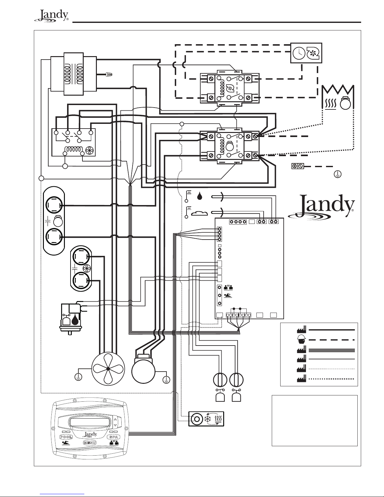
Wiring connections must be made exactly as
shown in the wiring diagram found on the inside of
the heat pump access compartment (see Figure 8 for
single phase electrical wiring and Figure 9 for 3-phase
electrical wiring). The heat pump must include a
definite means of grounding and bonding. There is a
bonding lug on the right side of the heat pump, where a
bond wire must be attached.
WARNING
ELECTRICAL SHOCK HAZARD. This heat
pump contains wiring that carries high voltage.
Contact with these wires may result in severe
injury or death. Disconnect power circuit before
connecting the heat pump
AVERTISSEMENT
POSSIBILITÉ DE CHOCS ÉLECTRIQUES.
Ce système de chauffage contient du fi lage
de haut voltage. Un contact avec ces fi ls peut
résulter en des blessures sérieuses ou la mort.
Débranchez le circuit de puissance avant de
relier la pompe à chaleur
AVISO
PELIGRO DE DESCARGA ELÉCTRICA.
Esta bomba de calor, contiene cableado
de alta tensión. El contacto con los cables
podría ocasionar lesiones graves o la muerte.
Desconecte el circuito de alimentación, antes
de conectar la bomba de calentar.
CAUTION
Label all wires prior to disconnection when
servicing controls. Wiring errors can cause
improper and dangerous operation. Verify proper
operation after servicing.
ATTENTION
Au moment de l’entretien des commandes,
étiquetez tous les fi ls avant de les débrancher.
Des erreurs de câblage peuvent entraîner un
fonctionnement inadéquat et dangereux.
PRECAUCIÓN
Proceda a etiquetar todos los cables antes de su
desconexión en los controles de mantenimiento.
Los errores de cableado pueden ocasionar
un funcionamiento peligroso e inadecuado.
Comprobar que el funcionamiento es correcto,
una vez efectuado el mantenimiento.

CHEMICAL LOOP
OR OPTIONAL CHLORINE
GENERATION SYSTEM
(JANDY AQUAPURE
CHEMICAL FEEDER
Jandy Heat Pump Models EE-Ti Installation and Maintenance Manual
VENT FOR INDOOR
INSTALLATION ONLY
POOL HEATER
®
SHOWN)
Sensors
A
u
q
P
a
u
e
r
Page 11
FILTER
POOL PUMP
FROM POOL OR SPA
CHECK VALVE
TO POOL OR SPA
Figure 4. Standard Plumbing Layout
POOL
RETURN
CHECK
VALVE
MANUAL BYPASS VALVE
HEATER
SPA
MAKE-UP
CHECK
VALVE
HEAT PUMP
FROM SOLAR
TO SOLAR
SPA
RETURN
POOL
DRAIN
SPA
DRAIN
Figure 5. Plumbing For Heating System Combinations
FILTER
FILTER
PUMP

Page 12
Jandy Heat Pump Models EE-Ti Installation and Maintenance Manual
Optional
2” PVC
3” PVC
To Pool
Isolation Valves
From Filter
Manual Bypass Valve
Figure 6. Two (2) Heat Pump Plumbing Layout
2” PVC
To Pool
Optional
Isolation Valves
From Filter
3” PVC
Figure 7. Four (4) Heat Pump Plumbing Layout
Manual Bypass Valve
Jandy Heat Pump Models EE-Ti Installation and Maintenance Manual
Page 13
24 VAC
PUMP TIME CLOCK
TRANSFORMER
24~
BL
Y
BK
BR
R
O
MAINTAIN
TEMP
24~
COMPRESSOR
HEATER
RELAY
BK
O
MODEL 3000
Y
BKYBKBK
FAN
Y
W
BK
R
Y
O
RELAY
YBK
BL
BL
W
BK
BL
MAIN
CONTACTOR
24~
W
BK
BK
L
1
BK
O
L
2
ONLY
GROUND
WATER TEMP
BK
AIR TEMP
COMPRESSOR
CAPACITOR
BK
BK
O
BL
R
GR Y BK R
RBK
R
BK
FAN
CAPACITOR
WATER
PRESSURE SWITCH
BR
BR/W
BL
R
Y
O
R
R
POWER
INTERFACE
AE/EE SERIES
230 VAC
SINGLE PHASE
60 Hz
WIRING DIAGRAM
R
R
Y
BK
BR
BR/W
GR
FAN
RBK BL
REFRIGERANT
PRESS SWITCH
COMPRESSOR
USER INTERFACE
HIGH
COM
Y
BLWW
W
JVA
INTAKE
BR BKBL
LOW
REFRIGERANT
PRESS SWITCH
REVERSING VALVE
(OPTIONAL)
JVA
RETURN
230~
230~
24~
24~
24~
230~
BK - BLACK/NOIR/NEGRO
BL - BLUE/BLEU/AZUL
BR - BROWN/MARRON/MARRON
BR/W - BROWN WITH WHITE TRACE/MARRON
AVEC UNE TRACE DE BLANC/MARRON
Y BLANCO
GR - GREEN/VERT/VERDE
O - ORANGE/ORANGE/ANARANJADO
R - RED/ROUGE//ROJO
W - WHITE/BLANC/BLANCO
Y - YELLOW/JAUNE/AMARILLO
FACTORY INSTALLED 230 VAC
FIELD INSTALLED 230 VAC
FACTORY 24 VAC HARNESS
FACTORY 24 VAC
FACTORY OPTIONAL 24 VAC
FACTORY OPTIONAL 230 VAC
Figure 8. EE-Ti Single-Phase Electrical Supply Wiring Diagram
H3007200E

Page 14
Jandy Heat Pump Models EE-Ti Installation and Maintenance Manual
TRANSFORMER
BL
Y
BL
Y
W
Y-OUT
24 VAC
YBK
Y
Y
THREE PHASE
LINE VOLTAGE
MONITOR
24~
PUMP TIME CLOCK
BK
R
COMPRESSOR
HEATER
O
MAINTAIN
TEMP
RELAY
BR
O
BK
MODEL 3000
Y
BKYBKBK
FAN
RELAY
BK
BL
BL
Y
C
Y
W
BK
R
BL
MAIN CONTACTOR
BK
BK
BK
Y
O
R
W
W
BK
O
L
1
L
2
L
3
GROUND
ONLY
WATER TEMP
AIR TEMP
L2
L1
BK
R
FAN
CAPACITOR
WATER
PRESSURE SWITCH
L3
W
GR Y BK R
BK
O
BL
R
BK
RR
BK
AE/EE SERIES
BR
BR/W
R
R
YBK
BR
BR/W
GR
FAN
RBK BL
REFRIGERANT
PRESS SWITCH
COMPRESSOR
USER INTERFACE
BL
R
Y
O
R
R
WW
HIGH
REVERSING VALVE
(OPTIONAL)
INTERFACE
COM
BLWW
Y
POWER
JVA
INTAKE
RETURN
W
BR BKBL
LOW
REFRIGERANT
PRESS SWITCH
230 VAC
THREE PHASE
60 Hz
WIRING DIAGRAM
JVA
230~
230~
24~
24~
24~
230~
BK - BLACK/NOIR/NEGRO
BL - BLUE/BLEU/AZUL
BR - BROWN/MARRON/MARRON
BR/W - BROWN WITH WHITE TRACE/MARRON
AVEC UNE TRACE DE BLANC/MARRON
Y BLANCO
GR - GREEN/VERT/VERDE
O - ORANGE/ORANGE/ANARANJADO
R - RED/ROUGE//ROJO
W - WHITE/BLANC/BLANCO
Y - YELLOW/JAUNE/AMARILLO
FACTORY INSTALLED 230 VAC
FIELD INSTALLED 230 VAC
FACTORY 24 VAC HARNESS
FACTORY 24 VAC
FACTORY OPTIONAL 24 VAC
FACTORY OPTIONAL 230 VAC
Figure 9. EE-Ti 3-Phase Electrical Supply Wiring Diagram
H3007300E
Jandy Heat Pump Models EE-Ti Installation and Maintenance Manual
Page 15
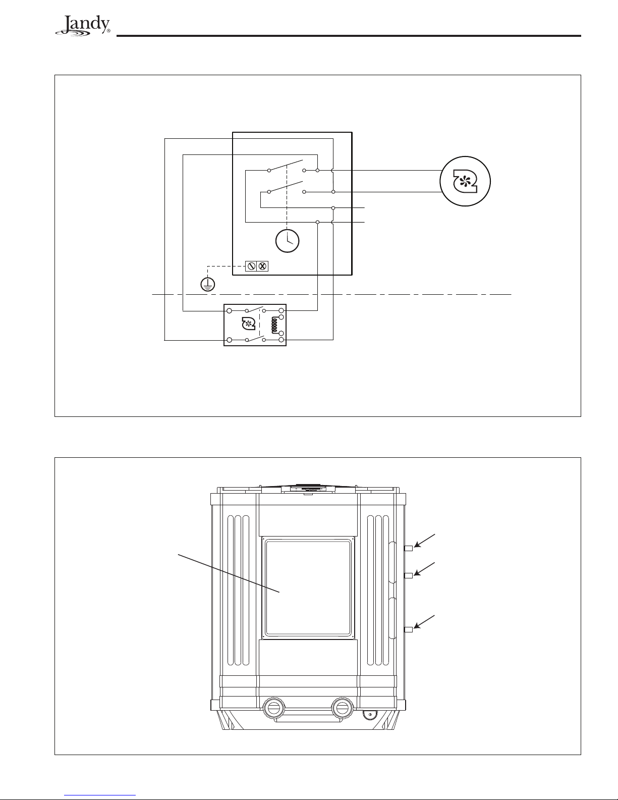
INTERMATIC MODEL T104 MECHANICAL TIMER
(NOT PROVIDED WITH HEAT PUMP)
4
2
3
CLOCK
EQUIPMENT
GROUND
NOTE:
INTERMATIC MODEL T104 (NOT PROVIDED WITH HEAT PUMP) WIRE CONNECTIONS SHOWN AS AN EXAMPLE,
OTHER MODELS MAY HAVE DIFFERENT CONNECTIONS. CONSULT TIMER MANUFACTURER FOR PROPER CONNECTIONS.
MOTOR
MAINTAIN TEMP (PUMP) RELAY
(SEE HEAT PUMP WIRING DIAGRAM)
1
L2
208 - 277 VAC
L1
FIELD INSTALLED COMPONENTS
HEAT PUMP COMPONENTS
PUMP
Figure 10. Example of “MAINTAIN TEMP” Wiring to the Time Clock
SERVICE ACCESS
PANEL (4 SCREWS)
MAINTAIN TEMP TO TIME
CLOCK CONNECTION
CONNECTOR FOR HIGH
VOLTAGE WIRES
CONNECTOR FOR LOW
VOLTAGE WIRES
Figure 11. EE-Ti Heat Pump Front View
Page 16
Jandy Heat Pump Models EE-Ti Installation and Maintenance Manual
4.2 Main Power
Electrical wiring to the heat pump must be in
accordance with the latest edition of the National
Electric Code (NEC), ANSI/National Fire Protection
Association (NFPA) 70 in the United States, and in
Canada, the Canadian Electrical Code (CEC) C22.1,
unless local code requirements indicate otherwise.
The heat pumps come factory-wired intended for
use with either 230 VAC, 60 Hz single phase or 3 phase
field electrical supply depending on the model. See the
rating plate for the electrical specifications. All wiring
must be done by a certified electrician.
The following is the procedure to wire the EE-Ti
to the electrical source specified on the Rating Plate:
1. Be sure the power to the circuit for the heat pump
is turned off.
2. Remove the four (4) screws that attach the service/
access panel to the heat pump unit (see Figure 11).
3. Remove the front cover of the sheet metal junction
box.
4. Electrical supply lines must be run through
watertight conduit. Run the wires and conduit from
the power source and connect them to the conduit
connection labeled “High Voltage Connection” on
the right side of the heat pump. See Figure 11 for
connection location.
5. Connect the wires to the terminals on the main
contactor as shown in the wiring diagrams. Refer
to Figures 8 and 9.
6. Connect the ground wire to the ground lug
provided in the electrical compartment.
7. Replace the cover of the junction box.
8. Replace the service access panel and replace the
screws to hold it in place.
9. Connect a copper bonding wire (8 AWG). (In
Canada, it shall be not smaller than 6 AWG (13.3
2
mm
) to the bonding lug on the right side of the
heat pump.
4.3 Bonding
CAUTION
This heater must be connected to a bonding
grid with a solid copper wire not smaller in
diameter than 8 AWG (In Canada, it shall be no
smaller than 6 AWG.)
ATTENTION
L’appareil de chauffage doit être connecté à une
grille de mise à la terre par un fi l de cuivre d’un
diamètre de calibre minimal 8. Au Canada, cela ne
devrait pas être inférieur à 6 AWG (13.3 mm
2
).
PRECAUCIÓN
Esta bomba de calor deberá estar conectado a
una rejilla de unión con hilo de cobre sólido, de
un diámetro no inferior a 8 AWG. En Canadá,
no será más pequeño de 6 AWG (13.3 mm
2
).
The National Electrical Code and most other U.S.
codes require that all metallic components of a pool
structure, including reinforcing steel, metal fittings,
and above ground equipment be bonded together with
a solid copper conductor not smaller than 8 AWG. The
heat pump, along with pumps and other pool equipment
must be connected to this bonding grid. A bonding lug
is provided on the right hand side of the heat pump to
ensure this requirement is met.
4.4 Pump Connection (Maintain Temp
Feature)
This feature allows the heat pump to turn on the
pool pump, bypassing the time clock setting, to maintain
the desired temperature. In order for the
TEMP feature to be functional, a dedicated line from
the pool pump time clock to the Maintain Temp (Pump)
MAINTAIN
Figure 12a. Remote Pool-Off-Spa Connection
(3-Wire Connection)
Figure 12b. AquaLink RS or Remote TSTAT
Connection (2-Wire Connection)

Jandy Heat Pump Models EE-Ti Installation and Maintenance Manual
Page 17
Relay is needed. See Figure 10.
4.5 Optional Remote Controls
Electrical wiring must be in accordance with all
applicable national and local codes and ordinances.
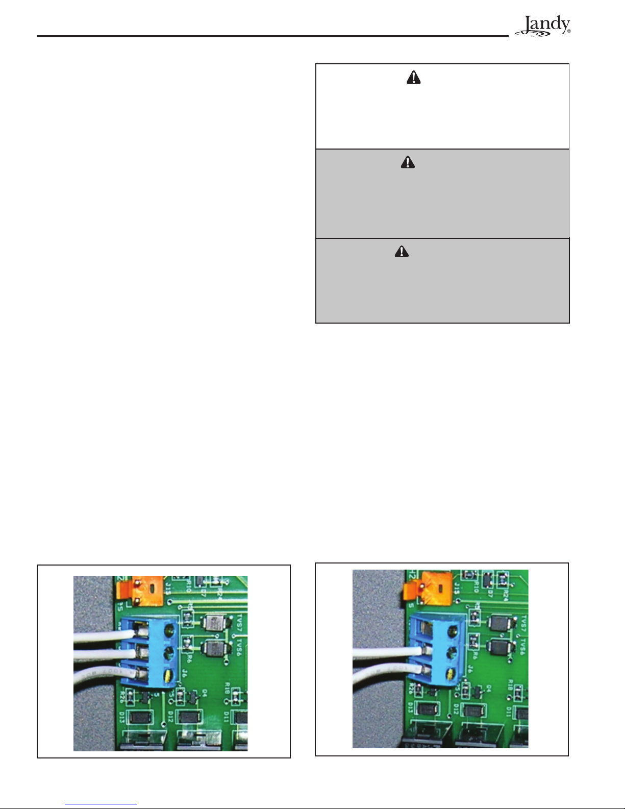
4.5.1 Connection to a Remote Pool-OffSpa Selector (3-Wire Connection)
4.5.1.1 Install the Remote Pool-Off-Spa
Selector
1. Turn off the power to both the pool/spa control
system and the heat pump unit.
2. Remove the screws that attach the service/access
panel to the heat pump unit and the cover to the
junction box (see Figure 11).
3. Run the wires from the pool/spa control system
into the conduit connection labeled “Low Voltage
Connection”, located on the lower right hand side
of the heat pump (see Figure 11).
4. Connect the wiring from the pool/spa control
system to the heat pump remote control terminal
(see Figure 12a).
5. Restore power to the heat pump and the pool/spa
control system.
4.5.1.2 Confi gure the Control Panel
1. Make sure the control is in the OFF mode.
2. To enter the Service Setup mode, press and hold
the MENU, POOL, and SPA buttons for 5
seconds.
NOTE The display will revert back to OFF after one
minute since the last key press.
3. Press the Up or Down button to display
REMOTE. Press the MENU button. The
SELECT REMOTE OFF (default remote)
appears, use the Up or Down button to scroll
through the Remote options. When you reach HI-
LO-COM, press the MENU button to select the
remote. Press POOL or SPA to exit the Service
Setup mode.
4.5.2 Two-Wire Connection to an
AquaLink® RS or TSTAT
4.5.2.1 Confi gure the AquaLink RS Control
System
1. Turn off the power to both the pool/spa control
system and the heat pump unit.
2. Connect two (2) wires to the AquaLink RS green
10-pin terminals 1 and 2.
3. Put DIP S2-1 (pin #1 of the 4 position DIP switch)
into the ON position (see Figure 13).
4.5.2.2 Install the Remote TSTAT
1. Turn off the power to both the pool/spa control
system and the heat pump unit.
2. Remove the screws that attach the service/access
panel to the heat pump unit and the cover to the
junction box (See Figure 11).
3. Run the wires from the pool/spa control system
into the conduit connection labeled “low voltage
connection”, located on the lower right hand side
of the heat pump (See Figure 11).
LED
will not
Green - Enabled
Red - On
come on
for Heat
Pump
S1
OFF ON
1 2 3 4 5 6 7 8
1 2 3 4
OFF ON
S2
Figure 13. AquaLink RS to EE-Ti Heat Pump
S1
S2
DIP Switches
S1 and S2
4321
RESET
AUTO
SERVICE
TIME OUT
4321
FILTER PUMP
UX 1
A
654321
AUX 3
AUX 2
Heat Pump Connections
Terminals 1 and 2
10987654321
RS6 & RS8 ONLY
RS8 ONLY
7
UX 6
UX
UX 4
A
A
A
AUX 5
POOL MODE
SPA MODE
SPA DRAIN
SOLAR
HEATER
SPA FILL
Connector for Low
Voltage Wires
Heat Pump

Page 18
Jandy Heat Pump Models EE-Ti Installation and Maintenance Manual
4. Connect the wiring from the pool/spa control
system to the heat pump remote control terminal
(See Figure 12b).
5. Restore power to the heat pump and the pool/spa
control system.
4.5.2.3 Confi gure the Control Panel
1. Make sure the control is in the OFF mode.
2. To enter the Service Setup mode, press and hold
the MENU, POOL, and SPA buttons for 5
seconds.
NOTE The display will revert back to OFF after one
minute since the last key press.
3. Press the Up or Down button to display
REMOTE. The SELECT REMOTE OFF
(default remote) appears, use the
Up or Down
button to scroll through the Remote options. When
you reach REMOTE TSTAT, press the MENU
button to select the remote. Press POOL or SPA
to exit the Service Setup mode.
®
4-Conductor
OR
RED
BLK
YEL
GRN
Wire
1234
JANDYAquaLink RS
06/26/04MON
6:00PM
FILTERPUMP OFF
AIR79°
EQUIPMENTON/OFF
ONETOUCH ON/OFF
MENU/ HELP
BLK
YEL
GRN
4321
S1
S2
RS Power
RED
654321
10987654321
4321
4321
RS6 & RS8 ONLY
RESET
P
4
5
2
3
X
AUTO
U
UX
UX 1
A
AUX
A
AUX
A
FILTER PUM
SERVICE
TIME OUT
Center
AU
OPTIONAL
RS8 ONLY
POOL MODE
6
SPA MODE
X
AUX 7
SPA DRAIN
SOLAR
HEATER
SPA FILL
4. Press SPA. For heating, adjust the setpoint to the
maximum setting. For chilling, adjust the setpoint
to the minimum setting.
4.5.3 Four-Wire Connection to AquaLink
RS 485 Communication
1. Confi rm the EE-Ti heat pump and AquaLink RS
software revisions are compatible (see Figure 14).
NOTE Only a revision "N", or higher, program chip in
the RS system will support the EE-Ti heat pump
interface.
2. Turn off the power to both the heat pump and
the RS control and open the RS Power Center
enclosure and remove the front dead panel.
3. Remove the two (2) screws holding the bezel in
place and turn the bezel over to view the circuit
board on the back.
4. Locate the programmed chip on the Power Center
Board. In the center of the chip is the revision
letter. If the revision letter is "
step 5. If the revision level is "
N" or higher go to
MMM" or lower,
replace the board or connect as shown in Section
4.5.2.
5. Use 22 gauge 4-conductor wire (Jandy Part No.
4278) to run between the heat pump and the RS
control, and match the wire color order.
6. The wires coming from the EE-Ti heat pump can
be “doubled up” on the red terminal bar with the
four (4) wires coming from the indoor controller.
NOTE If you need to install more than two (2) wires in
each terminal, order a Jandy Multiplex PCB Kit,
AE-Ti Heat Pump Power Interface
®
Figure 14. EE-Ti Heat Pump Connection to Power
Center
which includes the Multiplex Board (Jandy Part
No. 6584). Never put more than two (2) wires
into each of the pins of the terminal bar.
7. Check all wiring, then apply power to both the
heat pump and the RS control system. Operation
can be verifi ed in either Service or Auto mode. See
the RS Control System manual for instructions
about operation.
When the EE-Ti heat pump is first powered and
there is an RS control connected to the heat pump, the
display on the heat pump will show
ONLINE PUSH MENU TO DISABLE"
"JANDY REMOTE
. When the
EE-Ti heat pump is online with the RS control, all
functionality of the control on the heat pump is disabled.
The heat pump functions can be controlled only at the
RS unit.
To temporarily use the heat pump controls, press
the
MENU button. The message "JANDY REMOTE
ONLINE PUSH MENU TO DISABLE"
will disappear
from the heat pump display. All functionality has now
been returned to the control on the heat pump. In this
mode the RS unit is no longer controlling the heat
pump.
To return the functionality to the RS unit, cycle
(turn off and then turn on) the power to the heat pump,
or press the
MENU button for 5 seconds to enter the
User Setup Mode and then enable the Jandy Remote.

Jandy Heat Pump Models EE-Ti Installation and Maintenance Manual
Page 19
EE-Ti Heat Pump Power
Interface Software Rev.
3.0 or Later N or Later
NOTE If connecting more than two (2) items to the RS
Power Center red, 4-pin con nec tor, a Multiplex
PCB is required.
AquaLink RS Software
Revision
4.5.4 Connection to a Secondary User
Interface
1. Turn off the power to the heat pump.
2. Remove the four (4) screws that attach the service
access panel to the heat pump and remove the
cover to the junction box. See Figure 11.
3. Run four (4) 22 AWG solid copper wires into the
conduit labeled “Low Voltage Connection” located
on the lower right hand side of the heat pump. See
Figure 11. The wires may be up to 300 feet (91.4
m) in length.
4. Connect the wires to the 4 position terminal on
the upper left hand corner of the Power Interface
PC Board, labeled “User Interface1”. The wires
will be added to the existing wiring to the User
Interface installed on the heat pump.
5. Ensure the wiring is consistent when connecting
the wires to the second User Interface. For
example, BK goes to BK, O goes to O, etc.
6. Re-install the junction box cover and service
access panel and restore power to the heat pump.
Section 5. Operation
CAUTION
Do not use this heat pump if any part has
been under water. Immediately call a qualifi ed
service technician to inspect the heater and
replace any part of the control system which
has been under water.
ATTENTION
N’utilisez pas cet appareil s’il a été plongé
dans l’eau, même partiellement. Faites
inspecter l’appareil par un technicien qualifi é et
remplacez toute partie du système de contrôle
et toute commande qui ont été plongés dans
l’eau.
PRECAUCIÓN
No utilice esta bomba de calor si algunos de
sus componentes han estado debajo del agua.
Póngase inmediatamente en contacto con un
técnico de mantenimiento cualifi cado para que
inspeccione el equipo y reemplace cualquier
parte del sistema de control que haya estado
debajo del agua.
CAUTION
Keep all objects off the top of the heat pump.
Blocking air fl ow could damage the unit and
may void the warranty.
ATTENTION
Ne posez aucun objet sur le dessus de
l’appareil. Il pourrait empêcher la circulation de
l’air, ce qui risquerait d’endommager l’appareil
et d’annuler la garantie.
PRECAUCIÓN
Mantenga todos los objetos fuera de la parte
superior de la bomba de calor. La obstrucción
del fl ujo de aire podría dañar la unidad y
anular la garantía.
5.1 Initial Start-up Precautions
Be sure that there is water in the pool and that the
surface level is above the skimmer or other inlet of the
pool’s filter system.
With any new pool or spa installation, operate
the filter pump with the heat pump off long enough
to completely clean the water. This will remove any
installation residue from the water.
Clean the filter at the end of this operation before
starting the heat pump. When raising the temperature
of a cold pool, program the time clock to run the pump
continuously.
This lets the filter system and heat pump operate
continuously until the water reaches the temperature
setting on the temperature control. When that happens,
the heat pump will automatically shut off, but the filter
pump will keep running.
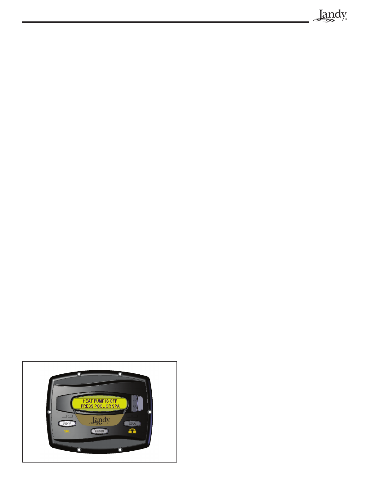
5.2 Operating the Controller
Your new EE-Ti heat pump is controlled by an
advanced microprocessor based controller that provides
a sophisticated yet simple interface to operate your heat
pump for maximum efficiency and enjoyment of your
pool. To locate the control buttons, see Figure 15.
5.2.1 Off Mode
When the control panel is turned off, the screen
displays
SPA
associated left green LED indicator will light and the
unit will display
NOTE XXX represents the current temperature setting
HEAT PUMP IS OFF PRESS POOL OR
.
5.2.2 Pool Mode - (Normal Heat)
To enable the pool mode, press POOL. The
SET:XXX°.
on the control. The default setting for pool
temperature is 80°F (26°C).
You can change the temperature set point by
Page 20
Jandy Heat Pump Models EE-Ti Installation and Maintenance Manual
pressing the Up or Down button. Repeatedly press
the Up or Down
button until you reach the desired
temperature set point. After 5 seconds of inactivity, the
new set point is stored in memory.
When the water temperature falls to 1 degree
below the temperature setting
and after a 5 minute
delay, the control will start the heat pump and the
associated right LED will light RED
.
5.2.3 Pool Mode - (Optional Maintain
Heat)
If connected, the Maintain Heat mode allows the
heat pump to monitor the temperature of the water 24
hours a day by turning the pool pump on and sampling
the water temperature.
A Maintain Temp Relay is required (provided) and
the feature must be enabled.
When the water temperature drops below the
programmed temperature set point, the control will start
the heat pump.
To operate in pool mode with the Maintain
Heat feature, press
the
Down button until MAINTAIN POOL HEAT is
displayed, press the
POOL, then press MENU, press
MENU button.
The associated left green LED indicator will
light and the unit will display
temperature set point by pressing the
SET:XXX°. Change the
Up or Down
button until the desired set point is displayed. After
5 seconds of inactivity, the new set point is stored in
memory.
5.2.4 Spa Mode - (Normal Heat)
To enable the spa mode, press SPA. The
associated left green LED indicator will light and the
unit will display
NOTE XXX represents the current temperature setting
on the control. The default setting for spa
temperature is 102°F (38°C).
SET:XXX°.
You can change the temperature set point by
pressing the
the Up or Down
Up or Down button. Repeatedly press
button until you reach the desired
temperature set point. After 5 seconds of inactivity,
the new set point is stored in memory. When the water
temperature falls to 1 degree below the temperature
setting
and after a 5 minute delay, the control will start
the heat pump and the associated right LED will light
RED.
5.2.5 Spa Mode - (Optional Maintain Heat)
If connected, the Maintain Heat mode allows the
heat pump to monitor the temperature of the water 24
hours a day by turning the spa pump on and sampling
the water temperature.
A Maintain Temp Relay is required (provided) and
the feature must be enabled.
To operate in spa mode with the Maintain Heat
feature, press
button until
the
MENU button. The associated left green LED
indicator will light and the unit will display
SPA, then press MENU, press the Down
MAINTAIN SPA HEAT is displayed, press
SET:XXX°.
Change the temperature set point by pressing the Up
or
Down button until the desired set point is displayed.
After 5 seconds of inactivity, the new set point is stored
in memory.
5.3 Operating Features of Hybrid Units
with Optional Chiller
NOTE The chiller is an optional equipment. Not all
units are provided with chiller.
5.3.1 Pool Mode - (Normal Chill)
To enable the pool mode, press POOL. The
associated left green LED indicator will light and the
unit will display
NOTE XXX represents the current temperature setting
on the control. The default setting for pool
temperature is 80°F (26°C).
Press the MENU button. Press the Up or Down
button until you reach POOL CHILL, press the MENU
button.
NOTE POOL CHILL will not be displayed if the unit is
not provided with chiller.
You can change the temperature set point by
pressing the
the Up or Down
temperature set point. After 5 seconds of inactivity,
the new set point is stored in memory. When the water
temperature rises to 1 degree above the temperature
setting
and after a 5 minute delay, the control will start
the heat pump and the associated right LED will light
GREEN
.
SET:XXX°.
Up or Down button. Repeatedly press
button until you reach the desired
Figure 15. Main Control Panel
5.3.2 Pool Mode - (Optional Maintain
Chill)
If connected, the Maintain Chill option mode
allows the unit to monitor the temperature of the
water 24 hours a day by turning the pool pump on and
sampling the water temperature.

Jandy Heat Pump Models EE-Ti Installation and Maintenance Manual
Page 21
A Maintain Temp Relay is required (provided) and
the feature must be enabled.
When the temperature of the water rises above the
desired temperature setting, the control will then turn on
the unit and the associated right green LED will light.
To operate in pool mode with the Maintain Chill
feature, press
the
Down button until MAINTAIN POOL CHILL is
POOL, then press MENU, then press
displayed, press the MENU button. The associated
left green LED indicator will light and the unit will
display
by pressing the
SET:XXX°. Change the temperature set point
Up or Down button until the desired set
point is displayed. After 5 seconds of inactivity, the new
set point is stored in memory.
5.3.3 Spa Mode - (Optional Maintain Chill)
If connected, the Maintain Chill mode allows the
heat pump to monitor the temperature of the water 24
hours a day by turning the spa pump on and sampling
the water temperature.
A Maintain Temp Relay is required (provided) and
the feature must be enabled.
When the water temperature rises above the
programmed temperature set point, the control will start
the heat pump.
To operate in the spa mode with the Maintain Chill
feature, press
button until
SPA, then press MENU, press the Down
MAINTAIN SPA CHILL is displayed,
press the MENU button. The associated left green LED
indicator will light and the unit will display
Change the temperature set point by pressing the
or
Down button until the desired set point is reached.
SET:XXX°.
Up
After 5 seconds of inactivity, the new set point is stored
in memory.
5.4 User Setup Options
The User Setup options allow the user to select
specific Languages, Temperature Scale, Spa Timer, and
Display Light options.
5.4.1 Language Setup
1. Make sure the control is in the OFF mode.
5.4.2 Temperature Scale Setup
1. Make sure the control is in the OFF mode.
2. To enter the User Setup mode, press and hold the
MENU button for 5 seconds.
3. To select temperature scale, use the
button to scroll through to display
USER SETUP TEMPERATURE SCALE
Up or Down
SELECT
. Press
the MENU button. The SELECT TEMP SCALE
°F
(default temperature scale) appears, use the
Up or Down button to scroll through the scale
options. When you reach the desired temperature
scale, press the MENU button to select. Press
POOL or SPA to exit the User Setup mode.
5.4.3 Spa Timer Setup
1. Make sure the control is in the OFF mode.
2. To enter the User Setup mode, press and hold the
MENU button for 5 seconds.
3. To select spa timer, use the
Up or Down button to
scroll through to display SELECT USER SETUP
SPA TIMER
SELECT SPA TIMER CONTINUOUS (default
. Press the MENU button. The
spa timer setting) is displayed. To turn the spa
on or off indefi nitely, press the MENU button to
select.
To select the length of time for the spa to run,
use the
SELECT SPA TIMER TIME SELECTION. Press
Up or Down button to scroll to display
the MENU button to select. The display SELECT
SPA TIME 01:00 HRS
(default time setting) is
displayed. Use the Up or Down button to select
the length of time for the spa to run (between
00:15 to 23:00 hours incremented by 00:15
minutes). Press the MENU button to select how
long the spa will run. Press POOL or SPA to exit
the User Setup mode.
2. To enter the User Setup mode, press and hold the
MENU button for 5 seconds.
NOTE The display will revert back to OFF after one
minute since the last key press.
3. To select a language, use the Up or Down button
to display SELECT USER SETUP LANGUAGE.
Press the MENU button. The SELECT
LANGUAGE ENGLISH
(default language)
appears, use the Up or Down button to scroll
through the language options. When you reach the
desired language, press the MENU button to select
the language. Press POOL or SPA to exit the
User Setup mode.
5.4.4 Display Light Setup
1. Make sure the control is in the OFF mode.
2. To enter the User Setup mode, press and hold the
MENU button for 5 seconds.
3. To select display light setup, use the
Up or Down
button to scroll through to display SELECT
USER SETUP DISPLAY LIGHT
. Press the
MENU button. The SELECT DISPLAY LIGHT
2 MIN TIMEOUT
(default display light setting) is
displayed. This option allows the display light to
turn off after 2 minutes. Press the MENU button

Page 22
Jandy Heat Pump Models EE-Ti Installation and Maintenance Manual
to select. Use the Up or Down button to scroll
to display SELECT DISPLAY LIGHT LIGHT
OFF
, this option allows the display light to turn
off, press the MENU button to select. Use the
Up or Down button to scroll to display SELECT
DISPLAY LIGHT LIGHT ON
, this option allows
the display light to turn on, press the MENU
button to select. Press POOL or SPA to exit the
User Setup mode.
5.5 Set Point Lockout
Make sure the control is in the ON mode (POOL
or SPA), press and hold the Up and Down buttons for
5 seconds. The set point will be locked and the control
will operate in the mode it was in when the Set Point
Lockout occurred. If an attempt to change the set point
is made while the control is in Set Point Lockout, the
control will display
the Set Point Lockout, press and hold the
SET POINT LOCKED. To unlock
Up and Down
buttons for 5 seconds. The unit will display SET POINT
UNLOCKED
.
5.6 Water Pressure Switch Adjustment
CAUTION
The water pressure switch should be adjusted
to turn the heater off when the pump is off.
Setting the switch to close at too low of a fl ow
can damage the appliance. Adjust the switch
to turn the heater off, not on.
ATTENTION
Le manocontact de pression d’eau doit être
réglé de façon à ce que l’appareil cesse
de fonctionner si la pompe s’arrête. Si le
manocontact est réglé pour se fermer lorsque
le débit d’eau est trop faible, l’appareil risque
de s’endommager. Réglez le manocontact
pour qu’il arrête l’appareil, et non pour qu’il le
mette en marche.
all basic installations as shown previously in Section
3.1 and Section 3.5 in this manual. Only adjust the
water pressure switch if the heat pump does not
operate when the proper flow is applied to unit or if
the heat pump does not shut off when the filter pump
is off. Occasionally, unusual plumbing configurations
or necessary restrictions in the plumbing may cause
pressure sensing problems. In these rare situations, the
plumbing system configuration may require adjustment
of the water pressure switch.
Adjustment of the pressure switch may be
necessary if any part of the filter system piping is 3 feet
(1 m) or more above the top of the heat pump jacket.
Do not adjust the pressure switch if the heat pump
is installed more than 11 feet (3.5 m) above or 5 feet
(1.5 m) below the pool surface. Consult your local
Jandy dealer for recommendations.
On some installations, the piping from the heat
pump to the pool is very short. The back pressure
could be too low to trigger the pressure switch. If this
happens, it may be necessary to install a directional
fitting or elbows where the return line enters the
pool. This will increase back pressure enough for the
heat pump to operate properly. If this configuration
is necessary, be sure to check that the system flow is
above the minimum requirement of 30 gpm (114 lpm)
after the direction fitting or elbow has been installed.
Make sure the pool filter is clean before making
any pressure switch adjustment: A dirty filter will
restrict the water flow and the pressure switch cannot be
adjusted properly.
To adjust the pressure switch:
1. Be sure that all valves in the system are set to
allow water fl ow through the heat pump. Start the
fi lter pump.
2. Set the heat pump control to call for heat. Set the
heat pump control to the POOL HEAT mode.
3. If the heat pump control displays “NO FLOW”,
then the fl ow in the system may be below the
minimum fl ow of 30 gpm (114 lpm) needed for
the safe operation of the heat pump. Investigate
and correct any fl ow problems before adjusting the
water pressure switch.
PRECAUCIÓN
El interruptor de la presión del agua, deberá
ajustarse de forma que el calentador se apague
cuando se apague la bomba. La calibración del
interruptor para que pueda apagarse con fl ujos
demasiado bajos podría estropear el equipo.
Ajuste el interruptor para apagar el calentador,
no para encenderlo.
The pressure switch is preset at the factory for
activation at 2 psi (14 kPa). This is the minimum
setting for the water pressure switch and works for
4. Remove the heat pump’s control access panel. The
water pressure switch is located in the lower left
corner of the control compartment.
5. After confi rming the fl ow rate is at a minimum
of 30 gpm (114 lpm), slowly rotate the thumb
wheel on the water pressure switch in a
counterclockwise direction until the “NO FLOW”
indicator disappears from the control display.
Remember that there is a time delay before the
heat pump compressor will start.
6. Once the heat pump is running, turn off the fi lter
pump. The heat pump should turn off immediately.
7. If the heat pump continues to operate when the

Jandy Heat Pump Models EE-Ti Installation and Maintenance Manual
Page 23
fi lter pump is off, turn the thumb wheel on the
water pressure switch in a clockwise direction
until “NO FLOW” is displayed on the control and
the heat pump shuts down.
8. Check the setting of the water pressure switch by
starting and stopping the fi lter pump and checking
the control display and operation of the heater
between each fl ow change.
9. If the water pressure switch cannot be adjusted
to accommodate the conditions listed above,
an external fl ow switch must be added to the
plumbing system to ensure that the heat pump will
not operate without the proper fl ow through the
heat exchanger.
Section 6. General Maintenance
6.1 Water Chemistry
Proper chemical balances are necessary for
sanitary bathing conditions as well as ensuring your heat
pump’s long life. Be sure to keep your chemical and
mineral concentration levels within the values indicated
in Table 3.
6.2 Winterizing
CAUTION
Failure to winterize could cause damage to the
heat pump and will void the warranty.
ATTENTION
La garantie sera annulée si l’appareil n’est pas
hivernisé convenablement.
PRECAUCIÓN
La falta de acondicionamiento de la bomba de
calor para el invierno podía causar daños y
anular la garantía.
In areas where freezing temperatures occur, you
should protect your pump, filter, and heat pump from
the elements. Perform the following steps to completely
drain the heat pump (see Figure 16).
1. Turn off the electrical power to the heat pump at
the main breaker panel.
2. Shut off the water supply to the heat pump.
NOTE For spas, it is also necessary to perform water
changes in addition to chemical treatment. It is
recommended to change the spa water every
60 days for light usage and every 30 days if
usage is heavy.
Table 3. Optimal Water Chemistry Ranges
Test Recommended Level
Free Chlorine or 1.0 to 3.0 ppm
Bromine 2.0 to 4.0 ppm
pH 7.2 to 7.8 (Ideal ranges being between 7.4 and 7.6)
Total Alkalinity (TA) 80 to 120 ppm
Calcium Hardness (CH) 175 to 400 ppm
Cyanuric Acid 30 to 50 ppm
Total Dissolved Solids (TDS) 1000 to 2000 ppm (Excluding dissolved NaCl from Salt
3. Disconnect the water inlet and outlet unions
located on the lower front panel of the heat pump.
The heat exchanger will drain through these water
connections.
Figure 16. Winterizing the EE-Ti Heat Pump
Chlorine Generator)
* Concentration levels taken from “Basic Pool and Spa Technology” published by APSP (Association of Pool and
Spa Professionals).
Page 24
Jandy Heat Pump Models EE-Ti Installation and Maintenance Manual
4. Cover only the top of the heat pump to prevent
debris from falling into the unit. Do not wrap the
sides of the heat pump with any plastic or other
material that will retain heat or moisture inside the
unit.
6.3 Spring Start-Up
If your heat pump has been winterized, perform
the following steps when starting the system in the
Spring:
1. Uncover the heat pump and inspect the top and
sides for any debris or structural problems.
2. Connect the water inlet and outlet unions located
on the lower front panel of the heat pump.
3. Turn on the fi lter pump to supply water to the
heat pump. Circulate water through the system
long enough to cycle all of the pool water through
the fi lter. Check for leaks in and around the heat
pump.
4. Check the pool chemistry and balance as
necessary.
5. Turn on the electrical power to the heat pump at
the main breaker panel.
6.4 Inspection and Service
Jandy heat pumps are designed and constructed
to provide long performance life when installed and
operated properly under normal conditions. Periodic
inspections are important to keep your heat pump
running safely and efficiently through the years.
6.4.1 Owner Inspection
CAUTION
Do not use this heat pump if any part has been
under water. Immediately call a qualifi ed service
technician to inspect the heater and replace any
part of the control system which has been under
water.
ATTENTION
N’utilisez pas cet appareil s’il a été plongé dans
l’eau, même partiellement. Faites inspecter
l’appareil par un technicien qualifi é et remplacez
toute partie du système de contrôle et toute
commande qui ont été plongés dans l’eau
PRECAUCIÓN
No utilice esta bomba de calor si algunos de
sus componentes han estado debajo del agua.
Póngase inmediatamente en contacto con un
técnico de mantenimiento cualifi cado para que
inspeccione el equipo y reemplace cualquier
parte del sistema de control que haya estado
debajo del agua.
Zodiac recommends that you inspect your heat
pump on a regular basis and especially after abnormal
weather conditions. The following basic guidelines are
suggested for your inspection:
1. Keep the top and surrounding areas of the heat
pump clear of all debris.
2. Keep all plants and shrubs trimmed and away from
the heat pump.
The heat pump will produce condensation (water)
while in operation. The heat pump base is designed to
allow the condensation to exit through the bottom drain
port when the unit is running. The condensation will
increase as the outdoor air humidity level increases.
Check the following at regular intervals to ensure proper
condensate drainage:
1. Visually inspect and clear the bottom drain ports
of any debris that could clog the ports.
2. Ensure that condensate water does not puddle
inside the heat pump
3. Ensure that condensate run-off is properly directed
away from the equipment pad to keep it from
undermining the pad.
During normal operation, the heat pump
produces three to five gallons of condensate per hour.
If condensate drainage is above this range during
operation or if water continues to drain from the base
when the heat pump is not in operation for more than an
hour, a leak in the internal plumbing may have occurred.
Call a qualified heat pump technician to investigate the
problem.
Keep the top air flow discharge and air flow intake
area clear of debris so the air flow though the heat pump
is not restricted. The cooler discharge air from the top
should not accumulate and be drawn into the side air
intake coils. Keep all plants and shrubs trimmed away
from the heat pump.
Make sure the front of the unit is accessible for
future service.
Keep lawn sprinkler heads from spraying on the
heat pump to prevent corrosion and damage. Use a
deflector if needed.
If the unit is installed under a very sharp roof pitch
or under a roof without a gutter, a gutter or diverter
should be fitted to prevent excessive water from pouring
down into the unit.
6.4.2 Professional Inspection
Inspections performed at least once a year by a
qualified technician are required to maintain your heat
pump’s safe and efficient operation. The following basic
safety checks must be performed.
1 Check for loose or broken wires and terminal
connections.
2. Verify the pressure switch operation. Turn the heat
pump OFF. Disconnect the power to the pump
time clock, or turn the pump time clock to an OFF
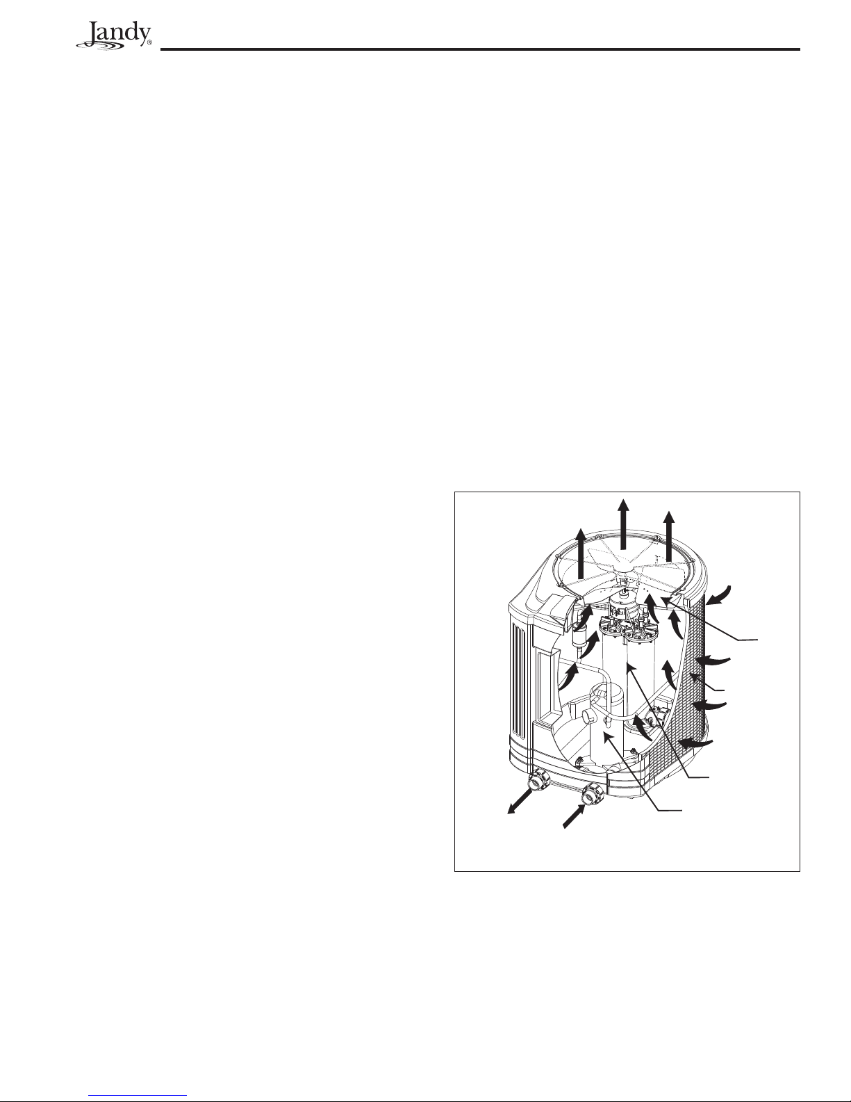
Jandy Heat Pump Models EE-Ti Installation and Maintenance Manual
R
Page 25
position. Turn the heat pump back ON. The heat
pump must not come on.
3. Inspect the electrical controls, specifi cally the
following:
a. High and Low limits
b. Pressure switch
c. Temperature control
4. Inspect the evaporator coil for blockage and clean
as necessary.
5. Check for spider webs or debris in the condensate
drain; clean if necessary.
6. Conduct a normal operating cycle and observe that
the unit operates properly.
Section 7. Professional Maintenance
and Service
7.1 Heat Pump Design
The Jandy heat pump is one of the most efficient
ways to heat a pool or spa. The heat pump transfers heat
from the outside air to the pool or spa water by means
of an internal heat exchanger.
When the fan is turned on, warm air is drawn
through the refrigerant charged evaporator, turning
the cold liquid refrigerant to a warm gas. The gas then
flows through the compressor where it is compressed
resulting in a much higher temperature.
The hot gas enters the heat exchanger where the
water extracts the heat. The pump pulls in cool pool
water, which in turn converts the hot gas back into a
liquid refrigerant and starts the cycle over again.
The EE-Ti heat pump uses a refrigerant called
R-410A. It is a non-ozone depleting refrigerant that
is accepted by the EPA. R-410A has higher operating
pressures and cooling capabilities than R-22, which is
the refrigerant used in the AE-Ti heat pump. Therefore,
R-410A should NEVER be used in any of the AE-Ti
heat pumps.
The EPA does not require certification to purchase
or use R-410A. It is recommended that service
personnel be trained in installation, service, brazing, and
maintenance procedures. They are similar to what the
industry has used for the R-22 system, however, they
should be redefined for the higher operating pressures.
NOTE The maximum heat output and effi ciency of
a heat pump is dependent upon the quality
and performance of the major components
used. Equally important are the environmental
conditions (for example, air temperature,
humidity, water temperature, and wind).
7.2 Heat Pump Components and
Operation
Evaporator - As air passes through the evaporator, the
refrigerant in the evaporator absorbs heat from the
ambient air. The warmer the ambient air and the
larger the surface area of the evaporator the more
heat it can collect.
Fan - The heat pump fan produces high volume airfl ow.
Adequate airfl ow is required to move warm air
through the large evaporator.
Compressor - The compressor compresses the
refrigerant gas to a higher pressure, increasing the
temperature.
Heat Exchanger - As the fi nal step to the heating
process, the heat exchanger transfers the heat
from the hot gas to the water. (Also known as a
condenser.)
Reversing Valve - (For Hybrid Units with Optional
Chiller and Hot Gas Defrost) The reversing valve
reverses the fl ow of the refrigerant, which results
in transferring cold gas to the water, thus lowering
the temperature.
COLD AIR OUT
FAN
EVAPORATO
COIL
WARM AIR IN
TITANIUM HEAT
EXCHANGER
COMPRESSOR
WATER
OUTLET
Figure 17. Heat Pump Operation Overview
WATER
INLET

Page 26
Jandy Heat Pump Models EE-Ti Installation and Maintenance Manual
Section 8. Troubleshooting
8.1 Troubleshooting Guide
The following table provides symptoms and solutions for general troubleshouting problems for the heat pump.
Table 4. Heat Pump Troubleshouting Guide
SYMPTOM CORRECTIVE ACTION
Heat pump will not start, no control board display. Breaker or fuse may be tripped. Reset breaker or check fuse. If
heat pump still does not run, call for service.
Three-phase models only - The phases may be
reversed or there may be a loss of phase, call for service.
Heat pump will not start, control board display working. Heat pump may be in delay count down of 5 minutes. Make
sure control board thermostat is calling for heater to come on
(check setting on thermostat and temperature reading). Make
sure heat pump is not in cooling mode.
Heat pump runs but does not heat. Verify cold air is blowing out the top of the heat pump. If the
heat pump has just been installed or if the pool water has been
allowed to cool significantly, it is necessary to run the heat
pump continually for 24-48 hours. If the heat pump has been in
operation for some time, increase the circulating pump time, or
switch the control board to Maintain Heat function. If heating a
spa, verify no air intake stand pipes are open. If heat pump still
does not heat, call for service.
Heat pump does not run and control board displays:
FAULTNO FLOW
Heat pump does not run and control board display shows:
FAULTHIGH REF PRESSURE
Heat pump does not run or short cycles and control board
display shows:
FAULTLOW REF PRESSURE
Heat pump leaking water. Possible heat exchanger or plumbing leak. Turn the heat
Verify circulating pump is on and all necessary valves are in the
correct positions. Verify filter and skimmers are clean. Check
water level in pool. Temporarily turn off all fountains and water
falls that bypass the heat pump water inlet. If this does not
correct the problem, call for service.
Verify circulating pump is on and that there are no water flow
restrictions to the heat pump. Make sure all necessary valves
are open or in the proper positions to allow proper water flow
to the heat pump. Verify filter and skimmers are clean. Check
for water level in the pool. This condition may also appear if
the heat pump has not been operated for an extended period.
To clear the condition, cycle the heat pump, on and off, up to 3
times. If this does not correct the problem, call for service.
Check that fan is operating and air is coming out of the top of
the heat pump, while short cycling. If heat pump does not run at
all, call for service.
pump off, then turn circulating pump off for at least one hour
to see if the water leak stops. If the water leak stops, normal
condensation is occurring. If the water leak continues, after the
heat pump is shut off for at least one hour, call for service.

Jandy Heat Pump Models EE-Ti Installation and Maintenance Manual
8.2 Diagnostics
In the event a pressure switch opens or another fault condition occurs, the LCD screen will display the fault until
the problem has been resolved. Please refer to the following table for the list of diagnostic conditions.
Table 5. Heat Pump Diagnostics
DIAGNOSTIC CONDITION DESCRIPTION
Page 27
FAULTNO FLOW
FAULTLOW REF PRESSURE
FAULTHIGH REF PRESSURE
FAULTHIGH WATER TEMP
FAULTSHORTED COIL SENSOR
-orFAULTOPEN COIL SENSOR
Low or restricted water flow through the heat pump.
The external bypass valve is in the wrong position, or the water flow switch
has malfunctioned. The water flow switch opens creating a fault and the
heat pump shuts off.
When the ambient temperature is low, the suction pressure can drop
significantly.
This fault will cause the low pressure switch to open and the control will
shut off the compressor.
When the head pressure builds too high, the high pressure switch will open
causing the heat pump to shut off immediately.
The control will sense this fault condition and shut off the compressor until
the switch re-closes.
When the POOL or SPA water temperature heats to the maximum allowed
temperature or above, there could be safety risks for anyone in the water.
The water thermostat will read this temperature and the control will shut off
the heat pump unless it is in CHILLER mode.
This feature also remains active when the control calls for heat through a
remote thermostat. This is to insure that water temperature does not go
to an abnormally high level due to a possible malfunction of the remote
sensor.
In the event that the coil temperature sensor malfunctions or is not
connected the control will shut off the heat pump.
FAULTSHORTED WATER SENSOR
-orFAULTOPEN WATER SENSOR
In the event that the water temperature sensor malfunctions or is not
connected the control will shut off the heat pump.
 Loading...