

Page 1
Installation Instructions
Jandy® Sheer Descent
Installation Manual
THIS UNIT MUST BE INSTALLED ACCORDING TO THE MANUFACTURER'S INSTALLATION
INSTRUCTIONS. PLEASE READ AND FOLLOW ALL INSTRUCTIONS. PLEASE SAVE THESE
INSTRUCTIONS.
PREPARATION AND INSTALLATION INSTRUCTIONS
This manual provides easy reference illustrations to help you identify each part of the Sheer Descent Waterfall. Use this
manual to guide you through the routine procedures and adjustments for a trouble free installation. These instructions were
developed with the aid of experienced contractors and has proven to be a simple, yet consistent and trouble free, method of
installation.
During all phases of the installation, care should be taken not to damage the Sheer Descent Waterfall. Keep the unit in the
original packaging until the site is prepared for permanent installation.
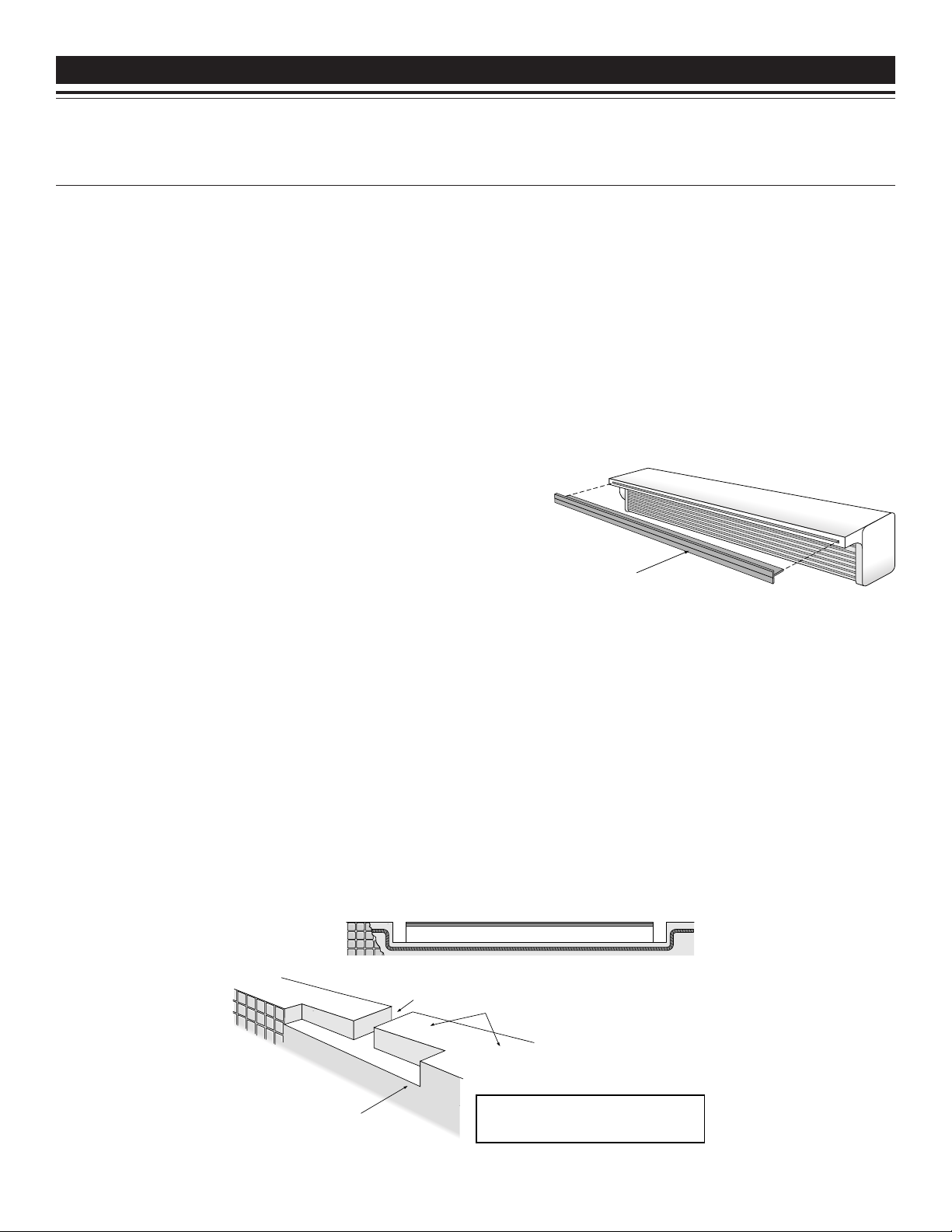
The Sheer Descent Waterfall is available in standard sizes from eight
inches to eight feet in length and is shipped complete with safety
tongue installed in the opening of the waterfall. See figure 1. The
protective tongue keeps the spillway opening clean and damage free.
DO NOT REMOVE THE TONGUE until the start up of the pool
equipment. The safety tongue must be left in the opening during the
entire installation, or damage to the unit, which would effect its ability
to perform, may occur.
Tongue
(Do not remove
prior to start-up)
Figure 1
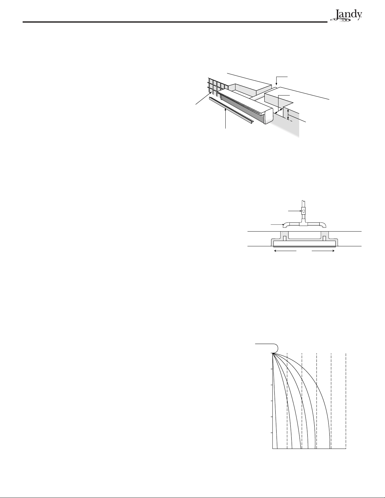
EXCAVATION & STEEL MODIFICATIONS
It is recommended that the area designated for the Sheer Descent Waterfall be marked off with colored stakes, yellow
construction ribbon, or similar material during the framing process, prior to excavation. In preparation for the installation
of the steel rebar, mark the EXACT area designated for the Sheer Descent Waterfall. To allow room for notching the bond
beam and installing the unit, offset the steel pattern by 3 inches below the original form and 1 inch on both ends of the
Sheer Descent Waterfall. For example, if the Sheer Descent Waterfall is 4 feet in length, offset the steel pattern to measure
3 inches down from the top of the frame and 50 inches in length (this allows 1 inch of space on each side of the Sheer
Descent unit). See figure 2.
Steel off set
Figure 2
Note: Notching of the bond beam is the next
step in the process. The change to the
steel will make the notch a simple procedure.
3½" wide x 3½"
deep notch
Finished notch in beam
2½"
Top of raised bond beam
Page 2
Page 2
Feet of Elevation
Feet of Projection
Gallons per minute per foot
Guideline is for 1ft. to 4ft models
7
1
2
3
12
9101215 20
Manifold
Rock trap
Sheer Descent Waterfall back feed
plumbing for 6, 7, & 8 ft. lengths.
Beam
Center
CONCRETE INSTALLATION AND MODIFICATIONS
As the concrete installation (or similar process) nears completion, a notch must be cut into the inner edge of bond beam in
the same area at which the steel was offset to allow for the installation of the Sheer Descent Waterfall. See figure 3.
CUTTING THE BOND BEAM
FOR SHEER DESCENT WATERFALL SIZES 8" THROUGH 5'
Select the EXACT location for the Sheer Descent Waterfall.
The notch in the bond beam should be cut 3½" deep by
2½" wide and 2" longer than the length of the proposed
Sheer Descent Waterfall (1" per side). For example, if a
Tile
4' model is to be installed, the notch length should be 50"
(48" + 1"+ 1" = 50"). In addition, mark a single slot on
the top of the beam in the center of the proposed notch
Tongue
3½" wide by 3½" deep. The notch will be used to plumb
1½" pipe to the Sheer Descent Waterfall. Mark the bond
beam and proceed with cutting the beam.
FOR SHEER DESCENT SIZES 6', 7', AND 8'
Mark and cut the beam as instructed previously, with the exception that two notches are required on the top of the beam
for piping. Longer waterfalls require more water; consequently, two plumbing lines are required. The top of the beam
should be marked for these units as follows: NOTE: These measurements are from the center of the Sheer Descent
Waterfall unit.
3½" wide x 3½" deep notch
2½"
3½"
Figure 3
Length Plumbing Location
6 foot 1 foot 6 inches to the right and to the left from the center line
7 foot 1 foot 9 inches to the right and to the left from the center line
8 foot 2 feet to the right and to the left from the center line
The notches should be 3½" wide by 3½" deep. See figure 4.
MAKE SURE THE CUTS IN THE BEAM ARE PROPERLY COMPLETED BEFORE PROCEEDING.
PUMP SIZING AND INSTALLATION OPTIONS
One of the advantages of the Sheer Descent Waterfall is the ability to provide a continuous sheet of water with a minimum
of water flow. A standard four foot model, for example, requires only 40 gallons per minute to operate. In order to size
your pump properly, refer to the Water Flow Requirement Chart. In most
cases, a properly sized standard swimming pool pump will operate the Sheer
Descent Waterfall and filter the pool with little loss of total water turnover. As
a general rule of thumb, the Sheer Descent waterfall requires approximately
10 gallons per minute per foot with little head loss. For more a dramatic effect,
more water gallonage can be applied to project the waterfall further away from
the wall. NOTE: When plumbing multiple falls, add the total length of
waterfalls together to determine GPM required. e.g. When plumbing two
(2) 6' units, you now have 12' of waterfall, which requires 120 gallons per
minute.
Figure 4
EXISTING POOL FILTER PUMP INSTALLATION
The installation of the Sheer Descent Waterfall using the main pool filter pump
is the most common plumbing system, due to the unique low flow aspect of the
waterfall system. Simply plumb a three way valve on the return line, after the
filter, and plumb the waterfall feed line in a minimum of 1½" PVC schedule
40 pipe. Units above 5' in length need a minimum of 2" plumbing.
Page 3
Page 3
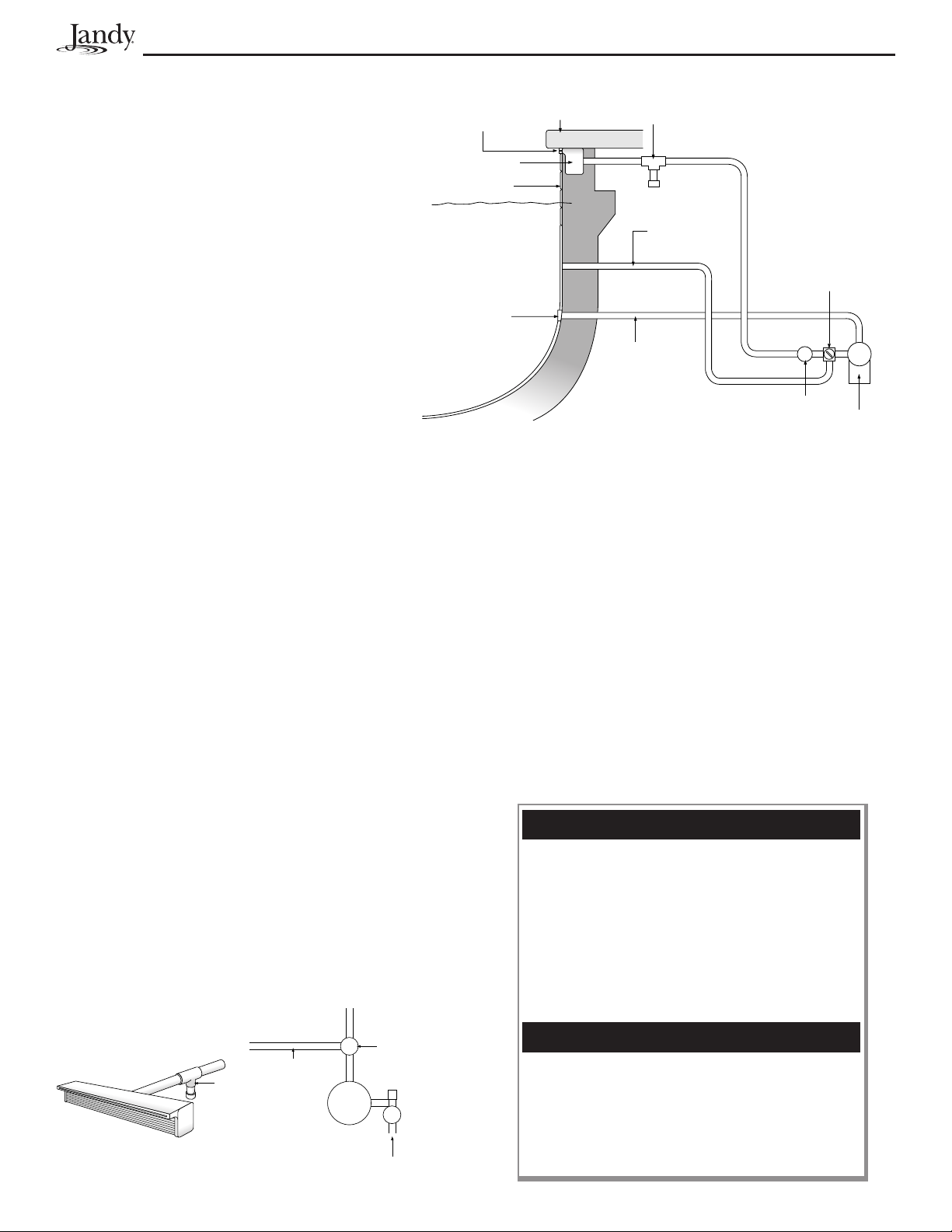
SEPARATE PUMP FOR THE SHEER DESCENT WATERFALL
If multiple waterfalls are being installed, or a Sheer
Descent Waterfall 6' or longer is being installed, we
Cantilever edge
recommend installing a separate pump. When
plumbing a pump dedicated for use by the Sheer
Descent, a separate suction line to the pool must be
Sheer Descent unit
Tile
plumbed. This should be plumbed in a minimum of
2" schedule 40 pipe.
Water line
NOTE: At least one anti-vortex safety suction
cover must be installed at pool side as a safety
precaution. The anti-vortex suction cover is
recommended to be positioned 18 inches above
Anti vortex
cover
the floor of the pool.
Next, a Sheer Descent filter/strainer (part #3456),
or equivalent, must be installed on the return side
of the pump, between the pump and the Sheer
Descent Waterfall. A FILTER IS REQUIRED
for separate pump installations, as large debris
must not be allowed to enter the Sheer Descent
unit. For installations requiring up to 60 gallons per minute, use one Sheer Descent filter. For higher water requirements,
use two or more filters plumbed in parallel. A separate return line, with a three way valve plumbed in such a way that
water can be balanced between the Sheer Descent Waterfall and return back to the pool, is also required. See figure 5.
Conventional
concrete decking
Suction line
Figure 5
Rock trap
Separate return
to pool
Jandy three
way valve
Sheer Descent
filter/strainer
Filter
pump
PLUMBING THE SHEER DESCENT WATERFALL
WATERFALL RETURN LINE PLUMBING
The waterfall feed line, from either the main filter pump or a separate pump, should be plumbed in a minimum of 1½"
PVC pipe. NOTE: Two inch plumbing or larger is suggested for waterfalls over 5 feet in total length. Refer to
Hydraulic Guideline Chart for specifications. The feed line should end near the back of the bond beam near the center of
the waterfall location.
It is important to have a valve located in a convenient location on the feed line to regulate the flow of water to the Sheer
Descent Waterfall. A Jandy three-way valve is suggested to be
used as the "T" from the return line of the pool to the Sheer
Descent Waterfall. A properly plumbed valve in that position will
allow full control of the water to the Sheer Descent, as well as to
the rest of the pool. In most cases, this valve can be located after
the filter near the equipment pad. See figure 6.
NOTE: All water to the Sheer Descent must be filtered.
Those systems using a separate pump must use our separate
filter (part #3456) to prevent debris from entering the Sheer
Descent unit.
Figure 6
Return to pool
Jandy three
Filter
way valve
Pump
Suction
from pool
Rock trap
Water to
sheer descent
H YDRAULIC GUIDELINE CHART
•Use minimum of 1½" pipe.
•Use minimum of 2" pipe for runs in excess of 60
feet or if Sheer Descent unit is over 5 feet.
•Dedicated plumbing lines are recommended.
•Maximum recommended flow for a typical installation:
1½" pipe for 60 GPM
2" pipe for 100 GPM
2½" pipe for 140 GPM
3" pipe for 225 GPM
Typical pump performance at 50 Feet of head
½ HP = 26 GPM
¾ HP = 58 GPM
1 HP = 68 GPM
1½ HP = 93 GPM
2 HP = 106 GPM
3 HP = 140 GPM
Page 4

Page 4
PLUMBING A SINGLE UNIT
All Backfeed Sheer Descent Waterfalls have the equivalent of standard 1½ inch pipe protruding from the back of the unit.
For waterfalls eight inches through five feet in length, this fitting is located in the center of the back of the waterfall.
For Sheer Descent waterfalls 6, 7, and 8 feet in length, two 1½ inch fittings are located as follows:
Sheer Descent Length Plumbing Location
6 foot 1 foot, 6 inches to the right and to the left from the center line
7 foot 1 foot, 9 inches to the right and to the left from the center line
8 foot 2 feet to the right and to the left from the center line
NOTE: A plumbing manifold is included with all Sheer Descent Waterfalls 6, 7, and 8 feet in length, to assist in
proper plumbing. Simply plumb the manifold to the waterfall, install the Rock Trap and the plumbing is complete!
Standard 1½" PVC fittings will glue over the 1½" pipe provided on all Sheer Descent Waterfalls. Make sure the fittings
are properly glued. Also, make sure the Rock Trap is properly installed as close to the waterfall as possible (figure 6).
See page 5 for Rock Trap installation instructions.
NOTE: A flow control valve must be plumbed in a convenient location on the supply line for regulation of the water
supply to the unit. See figure 7.
Ensure plumbing lines to unit are clear of debris.
Rock Trap
Notch in beam
Back Feed plumbing
for units 8"through 5'
Ensure plumbing is properly sized
Manifold
Beam
Rock Trap
Beam
Back Feed plumbing
for units 6', 7', & 8'
Figure 7
PLUMBING MULTIPLE UNITS
Plumbing two or more Sheer Descent Waterfalls together is done in exactly the same way as the installation procedure for a
single unit, explained previously, with the exception that additional two-way valves are required for each Sheer Descent
Waterfall. These valves regulate and balance the amount of water between the various waterfalls. For units 6', 7' and 8'
long, separate minimum 2" lines are required, with valves to regulate the balance. See to figure 8.
Make sure no debris is in any of the plumbing lines in the unit
Rock trap
Jandy
Valve
Sheer Descent Waterfall
back feed plumbing for
eight inch through five feet
Jandy
Valve
Rock trap
Sheer Descent Waterfall
back feed plumbing for
six, seven and eight feet
Figure 8
Page 5

Page 5
From pump
To sheer
descent
Screen
Debris
trap
INSTALLING THE SHEER DESCENT WATERFALL
The Sheer Descent Waterfall is generally installed by the tile installer. NOTE: The Sheer Descent Waterfall must be
installed prior to installing the decks and coping. Place the Sheer Descent Waterfall in the pre-cut notch in the bond
beam. Level the top of the Sheer Descent unit to the upper edge of the
bond beam with tile shims.
Sheer Descent Waterfall
NOTE: The top of the Sheer Descent is where the opening and
tongue are located. Fill the gaps around the unit with concrete
brown coat, or similar material, and surface the face of the Sheer
Descent unit in preparation for tile. The face of the Sheer Descent has
Spillway
Spillway must be
flush with tile or
overhang by 1/8"
(side view)
been designed to allow concrete to "grip" the surface and assure a strong
tile bond. Cut the tile to fit under the "lip" of the unit and secure with
"thin set" or similar compound. See figure 9.
Figure 9
Tile
Water line
Undercoat or browncoat
then thin set and tile
START UP INSTRUCTIONS
After the swimming pool is completed and filled with water, the Sheer Descent Waterfall is ready to be activated.
REMOVE THE TONGUE NOW. This must be done before water is diverted to the waterfall. Also, ensure the opening
is clean and clear of any debris. Turn the pump on. If the waterfall is plumbed with the main pool filter pump, allow the
pump to run a few minutes to clear the lines of debris. Slowly open the regulating valve and supply water to the Sheer
Descent Unit. Adjust the flow of water until the sheet of water extends out onto the pool surface. Allow for air to clear the
lines. This should only take a few minutes. The Sheer Descent Waterfall unit should now provide a clear, continuous sheet
of water.
In the event a separate pump was installed, make sure all valves are open prior to starting the pump. ENSURE ALL
LINES ARE CLEAR OF DEBRIS BEFORE STARTING. Start the pump and allow water to circulate through the
separate filter system and return line. Slowly open the valve to the waterfall and regulate to the desired setting. Allow a few
minutes to purge all air from the lines.
In order to prevent freeze damage to the system, the plumbing to the unit must be installed so water drains easily from the
system. The Sheer Descent Waterfall has been engineered to allow only a minimum of water to stay in the unit as long as
the plumbing is installed properly. For winterizing, blow all lines and follow normal procedure.
♦ Install the Rock Trap as close to the water fixture (waterfall, jets, etc.) as
♦ Rock Trap must be installed with debris collection chamber pointed DOWN.
♦♦
♦ Prior to gluing the Rock Trap, ensure flow arrow is properly aligned.
♦♦
♦♦
♦ NEVER install Rock Trap where debris chamber cannot be pointed DOWN.
♦♦
ROCK TRAP
INSTALLATION
OPTIONS
FREEZE PROTECTION AND WINTERIZATION
ROCK TRAP INSTALLATION INSTRUCTIONS (Rock Trap optional on some models)
possible, to assure maximum protection.
See figure 10.
Right
Rock trap
Wrong
Figure 10
Page 6

Page 6
SHEER DESCENT EXTENDED LIP WATERFALL
The Sheer Descent Extended Lip Waterfall is used for radius cuts or when the lip of the waterfall needs to extend over
wide objects such as brick, glass block, etc. The lip extension is 6" (the standard Sheer Descent Waterfall has a one inch
lip). Operation and installation of both products is identical, with the exception that the steel pattern and notch in the beam
may need to be altered to accommodate the lip width. NOTE: The extended lip must be fully supported. See figure 11.
Mortar will not stick to the plastic parts on the Sheer Descent Waterfall. When using various types of coping material,
consult with your decking contractor for appropriate installation and or modification to the installation.
Sheer Descent Extended Lip Waterfall
Figure 11
NOTE: The tongue must stay in place during entire
Tongue
installation, but make sure it is removed prior to system start
up. All aspects of the installation are the same as the
Brick
Brick
Brick
Over Brick/Rock Installation
Bond beam
Rock Trap
Tile
Bond beam
Over the Beam Installation
Notch back
of beam
standard model Sheer Descent Waterfall.
CUTTING THE LIP FOR CURVES OR CUSTOM INSTALLATIONS
The extended lip Sheer Descent Waterfall can be custom cut in the field to meet specific needs, such as curves, irregular
shapes, etc. In order to custom fit the waterfall, carefully measure the amount of extended lip to be removed. Remember to
leave enough room for tile and thin set, so the deepest edge of the radius cut will not be recessed from the tile line. NOTE:
Never remove more than 4½" of the extended lip, leaving a minimum of 1½" of lip. See figure 12. Remove the
protective tongue prior to cutting the waterfall. Remember to REPLACE THE TONGUE after cutting the radius to
protect the fall from construction debris. An additional tongue is provided in product packaging.
The waterfall must be cut with a coarse tooth saw blade. Running water can be applied to the surface being cut to keep the
blade cool. Caution must be taken to make the cut as smooth as possible to avoid a jagged edge. After cutting the
waterfall, insert the support removal tool (included in product packaging) 1 inch into the waterfall opening. Move the tool
around the opening. If the tool hits a support, use the notch in the tool to remove the support. See figure 13a. Make sure
all supports within 1 inch of lip opening are removed. See figure 13b. DO NOT LEAVE THE LOOSE SUPPORT
SECTION IN THE WATERFALL.
After removing sections of the supports, use a coarse grade of sandpaper to smooth the edges of the waterfall, follow with
a fine grade of sandpaper to get the edge as smooth as possible. A sanding block is recommended to avoid rounding the
edges of the waterfall.
Insert the tongue back into the opening and continue installation, following the installation instructions for the standard
Sheer Descent Waterfall. NOTE: Two tongues are provided with every extended lip waterfall. Use the appropriate
tongue to fully cover the opening. The long tongue can be "V" cut, as shown in figure 13b, to allow for curved
installations. The smaller piece of tongue, which is provided in the packaging, is used to make up any sizing
difference due to the radius cut. When installing the smaller piece, make sure the fit is tight and no debris can enter
the spillway opening.
Convex Curve
Break off lip supports
1" from lip of waterfall
Support
removal tool
Convex Curve
Insert Tongue Assemble
Concave Curve
Break off lip supports
1" from lip of waterfall
1½" minimum
¼"
6"
¾"
½"
Support
removal tool
Concave Curve with Tongue
Insert Tongue Assemble
Figure 12 Figure 13a Figure 13b
Page 7

SHEER DESCENT WATERFALL RADIUS CUT GUIDELINE
Sheer Descent Waterfall
extended lip radius installation
Do not
remove more
than 4½"
NOTE: Never remove more than 4½" of the extended lip, leaving a minimum of
1½" of lip. The top of the beam, where the Sheer Descent unit is to be installed,
should be a minimum of 9" thick. When designing custom curves for the Sheer
Descent Extended Lip models, please refer to the following Minimum Radius Guidelines
Table to select the correct Sheer Descent model. Super Radius models accommodate
very tight radius curves and are available by special order.
MINIMUM RADIUS GUIDELINES TABLE KEY
Sheer Descent Model Abbreviation Customize Cut
Extended Lip EL Field Cut or Factory Cut
Super Radius SR FACTORY CUT ONLY
S
HEER DESCENT WATERFALL LENGTH
1' 1.5' 2' 3' 4' 5' 6' 7' 8'
Radius
1' EL - - - - - - - -
1.5' EL EL - - - - - - -
2" EL EL EL SR
2.5' EL EL EL SR - - - - -
3' EL EL EL SR SR - - - -
3.5' EL EL EL SR SR - - - -
4' EL EL EL EL SR - - - -
4.5' EL EL EL EL SR SR - - -
5' EL EL EL EL SR SR - - -
5.5' EL EL EL EL SR SR - - -
6' EL EL EL EL EL SR SR - -
6.5' EL EL EL EL EL SR SR - -
7' EL EL EL EL EL SR SR - -
7.5' EL EL EL EL EL SR SR - -
8' EL EL EL EL EL SR SR - -
8.5' EL EL EL EL EL SR SR SR -
9' EL EL EL EL EL SR SR SR -
9.5' EL EL EL EL EL EL SR SR -
10' EL EL EL EL EL EL SR SR -
10.5' EL EL EL EL EL EL SR SR -
11' EL EL EL EL EL EL SR SR -
12' EL EL EL EL EL EL SR SR -
12.5' EL EL EL EL EL EL EL SR SR
13' EL EL EL EL EL EL EL SR SR
Page 7
Before proceeding, make sure the pump system is fully functional and activated. Also, ensure all air is purged from
plumbing lines.
Problem «
The Sheer Descent Waterfall is not
completely smooth. A gap in the sheet
of the water is present.
Problem «
Where multiple Sheer Descent
Waterfalls are installed, one of the
waterfalls is stronger than the other.
TROUBLE SHOOTING GUIDE
Cause «
Debris in the plumbing has lodged in
the opening of the waterfall.
Cause «
The water supplied to the units is not
properly balanced.
Solution
Use a credit card or similar object and
gently position it inside the opening
while the waterfall is on. Slide it
along the opening to the point where
the debris is located and gently pull
the debris through the opening.
Solution
Adjust the valves for each waterfall
until the proper effect and balance is
achieved. See figure 8 for valve
location.
Page 8

LIMITED WARRANTY
Thank you for purchasing Jandy® pool and spa products. Water Pik Technologies (manufacturer of Jandy
products, including Laars
®
pool and spa heaters, Air Energy Heat Pumps, and Clormatic Electronic Chlorine
Generators) warrants all parts to be free from manufacturing defects in materials and workmanship for a period of
one year from the date of retail purchase, with the following exceptions:
AquaLink
•
NeverLube
•
AquaPure
•
®
RS units installed with Jandy Surge Protection Kits will be covered for two years.
®
valves are warranted for the life of pool and/or spa on which they were originally installed.
TM
Electronic Chlorine Generator Electrolytic Cells carry a 5 year limited warranty on a prorated basis.
This warranty is limited to the first retail purchaser, is not transferable, and does not apply to products that have
been moved from their original installation sites. The liability of Water Pik Technologies shall not exceed the
repair or replacement of defective parts and does not include any costs for labor to remove and reinstall the
defective part, transportation to or from the factory, and any other materials required to make the repair. This
warranty does not cover failures or malfunctions resulting from the following:
1. Failure to properly install, operate or maintain the product(s) in accordance with our published Installation,
Operation and Maintenance Manuals provided with the product(s).
2. The workmanship of any installer of the product(s).
3. Not maintaining a proper chemical balance in your pool and/or spa [pH level between 7.2 and 7.8, Total
Alkalinity (TA) between 80 to 120 ppm, Total Dissolved Solids (TDS) less than 2000].
4. Abuse, alteration, accident, fire, flood, lightning, rodents, insects, negligence or acts of God.
5. Scaling, freezing, or other conditions causing inadequate water circulation.
6. Operating the product(s) at water flow rates outside the published minimum and maximum specifications.
7. Use of non-factory authorized parts or accessories in conjunction with the product(s).
8. Chemical contamination of combustion air or improper use of sanitizing chemicals, such as introducing
sanitizing chemicals upstream of the heater and cleaner hose or through the skimmer.
9. Overheating, incorrect wire runs; improper electrical supply; collateral damage caused by failure of O-Rings,
DE grids, or cartridge elements; or damage caused by running the pump with insufficient quantities of water.
LIMITATION OF LIABILITY:
This is the only warranty given by Water Pik Technologies. No one is authorized to make any other warranties on
Water Pik Technologies' behalf. THIS WARRANTY IS IN LIEU OF ALL OTHER WARRANTIES, EXPRESSED
OR IMPLIED, INCLUDING BUT NOT LIMITED TO ANY IMPLIED WARRANTIES OF FITNESS FOR A
PARTICULAR PURPOSE AND MERCHANTABILITY. WATER PIK TECHNOLOGIES EXPRESSLY DISCLAIMS
AND EXCLUDES ANY LIABILITY FOR CONSEQUENTIAL, INCIDENTAL, INDIRECT OR PUNITIVE
DAMAGES FOR BREACH OF ANY EXPRESSED OR IMPLIED WARRANTY. This warranty gives you specific
legal rights. You may also have other rights which vary by state or province.
WARRANTY CLAIMS:
For prompt warranty consideration, contact your dealer and provide the following information: proof of purchase,
model number, serial number and date of installation. The installer will contact the factory for instructions
regarding the claim and to determine the location of the nearest designated service center. If the dealer is not
available, you can locate a service center in your area by visiting www.jandy.com or by calling our technical
support department at (707) 776-8200 extension 260. All returned parts must have a Returned Material
Authorization number to be evaluated under the terms of this warranty.
A Water Pik Technologies Company
480 S. Service Road West • Oakville, Ontario, Canada L6K 2H4
6000 Condor Drive • Moorpark, CA USA 93021
Sheet #0129, Rev. D
• 707.776.8200 • Fax 707.763.7785
• 905.844.8233 • Fax 905.844.2635
Litho in U.S.A. © Water Pik Technologies 0404
 Loading...