

Jandy CPLVLEDS30, CPLVLEDP100, CPLVLEDS50C, CPLVLEDS100C, CPLVLEDP100C Installation Manual
...Page 1

Installation Data
Installation Manual
Jandy® WaterColors LED,
Underwater Large and Small Light
FOR YOUR SAFETY - This product must be installed and serviced by a pro fes sion al pool/spa
builder or service technician. The procedures in this manual must be followed ex act ly. Failure to follow warning notices and instructions may result in property damage, serious injury,
or death. Improper in stal la tion and/or operation will void the war ran ty. Before installing this
product, read and follow all warning notices and instructions that accompany this light.
H0305500A
WARNING
Page 2

Page 3

Table of Contents
Page 3
Section 1. Safety Information ...................... 4
Section 2. Product Description and Model
Numbers ...................................... 5
Section 3. Installing Jandy Light Fixture
during New Construction ...........6
3.1 Preparing the Light Fixture for Installation ...6
3.2 Installing the Light Fixture ...........................7
Section 4. Replacing Jandy Light Fixture in
an Existing Pool or Spa .............7
4.1 Preparing the Light Fixture for
Replacement................................................7
4.2 Replacing the Light Fixture .........................8
Section 5. Wiring Options for Controlling
Jandy WaterColors LED Lights .9
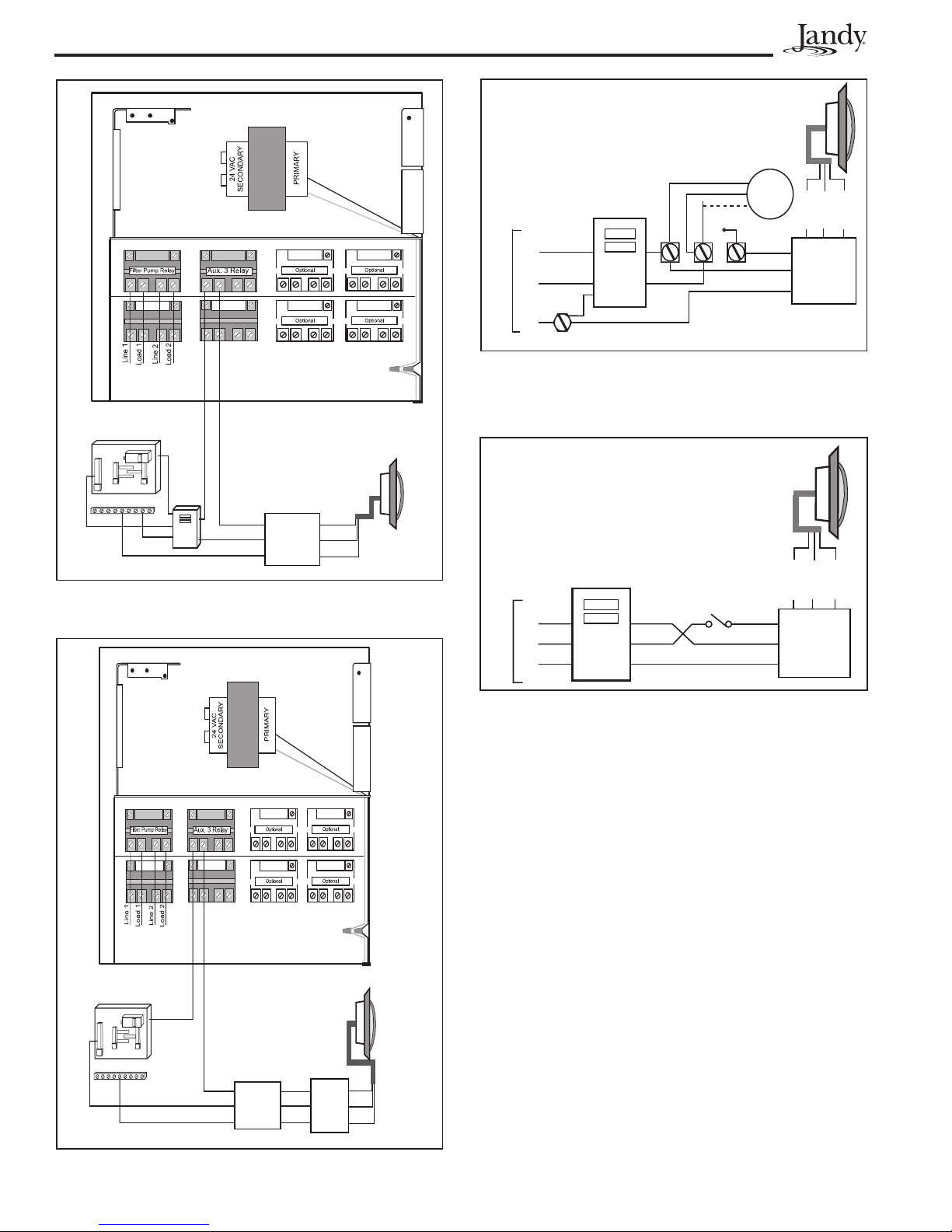
5.1 Wiring to an AquaLink® RS Control System .9
5.2 Wiring to a Time Clock .................................9
5.3 Wiring to a Switch ........................................9
Section 6. Jandy WaterColors LED Light
Operating Instructions ............... 9
6.1 To Operate the Light and Change Colors ....9
6.2 To Reset to the Beginning of the Color
Sequence...................................................11
Section 7. Replacing Light Engine (PCB) .11
Section 8. Twelve (12) Volt Installation .....14
Section 9. Exploded View and
Replacement Parts ...................15
9.1 Jandy Large WaterColors LED Light .........15
9.2 Jandy Small WaterColors LED Light .........16
Figures and Tables
Figure 1. Jandy Digital Color Light Installation ..........6
Figure 2. 120-Volt Jandy WaterColors Light Wiring
Diagram ...................................................10
Figure 3. 12-Volt Jandy WaterColors Light Wiring
Diagram ...................................................10
Figure 4. Wiring the Jandy WaterColors Light to a
Time Clock ...............................................10
Figure 5. Wiring the Jandy WaterColors Light to a
Switch ......................................................10
Figure 6. Removing the Jandy WaterColors Light
Assembly for Light Engine Replacement .12
Figure 7. Small Light Engine (PCB) Replacement
and Wiring ................................................13
Figure 8. Large Light Engine (PCB) Replacement
and Wiring ................................................13
Figure 9. Alignment of the Lens, Face Ring, Housing
and Clamps for WaterColors Lights .........14
Figure 10. Cross Section of Jandy WaterColors
LED Light .................................................14
Figure 11. Jandy Large WaterColors LED Light
Exploded View .........................................15
Figure 12. Jandy Small WaterColors LED Light
Exploded View .........................................16
Table 1. Jandy WaterColors Lights Sequence .........9
Table 2. Light Specifications .................................. 11
Page 4

Page 4
Section 1. Safety Information
IMPORTANT SAFETY INSTRUCTIONS PERTAINING TO A RISK OF
FIRE, ELECTRIC SHOCK, OR INJURY TO PERSONS
READ AND FOLLOW ALL INSTRUCTIONS
When installing and using this electrical equipment, basic safety precautions should always be followed, including the
following:
WARNING
RISK OF ELECTRICAL SHOCK OR ELECTROCUTION.
licensed or certified electrician in accordance with the National Electrical Code and applicable local codes and
ordinances. Improper installation will create an electrical hazard, which could result in death or serious injury to
pool or spa users, installers, or others due to electrical shock, and may also cause damage to property. Read
and follow the specific instructions below.
This underwater light must be installed by a
WARNING
Before installing this underwater light, read and follow all warning notices and instructions accompanying this
light. Failure to follow safety warnings and instructions can result in severe injury, death, or property damage.
Call (707) 776-8200 for additional free copies of these instructions.
CAUTION
Except when the Jandy WaterColors LED Lights are installed in an area of the swimming pool that is not used
for swimming and the lens is adequately guarded to keep any person from contacting it, the light shall be
installed in or on a wall of the pool, with the top of the lens opening not less than 18 inches (457 mm) below the
normal water level of the pool
ATTENTION INSTALLER: This manual contains important information about the
installation, operation and safe use of this product. This information should be given to the
owner/operator of this equipment.
NOTICE
The Jandy WaterColors LED Lights are intended for installation in fresh water and salt water swimming pools.
It is important to ensure that the wet niches in which the lights are installed are intended for their appropriate
application, either fresh water or salt water pools.
SAVE THESE INSTRUCTIONS
Page 5

Section 2. Product Description and Model Numbers
Page 5
Jandy® Model # Jandy® WaterColors
Light Size
CPLVLEDS30 Large 12 Volt AC 4.0 30 feet Stainless Steel
CPLVLEDS50 Large 12 Volt AC 4.0 50 feet Stainless Steel
CPLVLEDS100 Large 12 Volt AC 4.0 100 feet Stainless Steel
CPLVLEDP100 Large 12 Volt AC 4.0 100 feet Plastic
CPLVLEDS50C Large 12 Volt AC 4.0 50 feet Stainless Steel
CPLVLEDS100C Large 12 Volt AC 4.0 100 feet Stainless Steel
CPLVLEDP100C Large 12 Volt AC 4.0 100 feet Plastic
CPHVLEDS30 Large 120 Volt AC 0.4 30 feet Stainless Steel
CPHVLEDS50 Large 120 Volt AC 0.4 50 feet Stainless Steel
CPHVLEDS100 Large 120 Volt AC 0.4 100 feet Stainless Steel
CPHVLEDP100 Large 120 Volt AC 0.4 100 feet Plastic
CPHVLEDS150 Large 120 Volt AC 0.4 150 feet Stainless Steel
CPHVLEDS250 Large 120 Volt AC 0.4 250 feet Stainless Steel
CPHVLEDS50C Large 120 Volt AC 0.4 50 feet Stainless Steel
CPHVLEDS100C Large 120 Volt AC 0.4 100 feet Stainless Steel
CPHVLEDP100C Large 120 Volt AC 0.4 100 feet Plastic
CSLVLEDS30 Small 12 Volt AC 2.0 30 feet Stainless Steel
CSLVLEDS50 Small 12 Volt AC 2.0 50 feet Stainless Steel
CSLVLEDS100 Small 12 Volt AC 2.0 100 feet Stainless Steel
CSLVLEDP100 Small 12 Volt AC 2.0 100 feet Plastic
CSLVLEDS50C Small 12 Volt AC 2.0 50 feet Stainless Steel
CSLVLEDS100C Small 12 Volt AC 2.0 100 feet Stainless Steel
CSLVLEDP100C Small 12 Volt AC 2.0 100 feet Plastic
CSHVLEDS30 Small 120 Volt AC 0.2 30 feet Stainless Steel
CSHVLEDS50 Small 120 Volt AC 0.2 50 feet Stainless Steel
CSHVLEDS100 Small 120 Volt AC 0.2 100 feet Stainless Steel
CSHVLEDP100 Small 120 Volt AC 0.2 100 feet Plastic
CSHVLEDS150 Small 120 Volt AC 0.2 150 feet Stainless Steel
CSHVLEDS250 Small 120 Volt AC 0.2 250 feet Stainless Steel
CSHVLEDS50C Small 120 Volt AC 0.2 50 feet Stainless Steel
CSHVLEDS100C Small 120 Volt AC 0.2 100 feet Stainless Steel
CSHVLEDP100C Small 120 Volt AC 0.2 100 feet Plastic
Voltage Amps Cord
Length
Face Ring
Material
Page 6

Page 6
Pentair
®
and Sta-Rite
®
are registered trademarks of Pentair, Inc.
Hayward
®
is a registered trademark and DuraNiche
™
is a trademark
of Hayward Pool Products, Inc.
Section 3. Installing Jandy Light
Fixture during New
Construction
WARNING
Risk of Electrical Shock or Electrocution.
This underwater light must be installed by a licensed
or certified electrician or a qualified pool serviceman
in accordance with the National Electrical Code and
all applicable local codes and ordinances. Improper
installation will create an electrical hazard, which
could result in death or serious injury to pool or spa
users, installers or others due to electrical shock,
and may also cause damage to property.
Always disconnect the power to the color light at the
circuit breaker before installing or servicing the light.
Failure to do so could result in death or serious injury
to serviceman, pool or spa users or others due to
electrical shock.
3.1 Preparing the Light Fixture for
Installation
NOTE The electrician must complete preparatory
steps before light fixture is installed. See
Figure 1.
Ensure that the pool meets the requirements of the
current National Electrical Code and all local codes
and ordinances. A licensed or certifi ed electrician must
install the electrical system to meet or exceed those
requirements before the underwater light is installed.
Some of the requirements of the National Electrical
Code, which the pool electrical systems must meet, are
as follows:
5. The wet niche must be properly electrically
bonded and grounded via the No. 8 AWG ground
connector located at the rear of the niche; see
Figure 1.
NOTE To be certain that the pool’s electrical system
meets all applicable requirements, the
electrician should also consult the local building
department.
Use only approved wet niches (see following note) to
ensure a safe and proper installation.
NOTE Jandy lights are ETL listed (ETL report/file
3141154CHI) for installation with only the
following manufacturer’s wet niche fixtures:
Large Niche Model Numbers:
Jandy: PLNICLRG, PLNICVFLRG,
SSNICLRG1R, SSNICLRG1S
Pentair: 620004, 78210200 thru 700,
78210401, 79206700
Hayward DuraNiche: SP0600U
Sta-Rite: 05161-2352 thru 2369, 05163-2395
thru 2396
Small Niche Model Numbers:
Jandy: PLNICSM, SSNICSM,
Pentair: 78241100, 78242200, 78242300
78243100 thru 300, 78244100 thru 300,
79206600
Hayward DuraNiche: SP0601U
Sta-Rite: 05166-1017 thru 1034, 05167-1035
thru 1037
®
Pentair
and Sta-Rite
®
Hayward
of Hayward Pool Products, Inc.
is a registered trademark and DuraNiche
®
are registered trademarks of Pentair, Inc.
™
is a trademark
1. The lighting circuit must have a Ground Fault
Circuit Interrupter (GFCI) for 120 volt models,
and must have an appropriately rated circuit
breaker.
2. The junction box (or, for 12 volt models, the low
voltage transformer) must be located at least eight
(8) inches above water level, at least four (4)
inches above ground level, and at least four (4)
feet from the edge of the pool; see Figure 1.
3. The light fi xture and all metal items within fi ve
(5) feet of the pool must be properly electrically
bonded to a reliable point of grounding.
4. The wet niche must be properly installed so that
the top edge of the underwater light’s lens is at
least 18 inches below the surface of the water in
the pool; see Figure 1.
To GFCI, Circuit
Breaker and
Power Source.
48"
min.
8" min. Junction Box or Low
Voltage Transformer, to the
max water level of the pool.
18" min. to top of Lens.
Concrete must be cut
back around Niche to
allow for a compacted
plaster seal.
11.50"
Coil 4 ft. of light cable
around Fixture.
Rigid
Conduit
4" min.
#8 AWG Ground
Connector bonding
is located at rear
of niche.
16”
Figure 1. Jandy Digital Color Light Installation
Page 7

Page 7
3.2 Installing the Light Fixture
NOTE Perform these steps only after the electrical
system requirements are met.
1. Feed cord through conduit to junction box, leaving
at least four (4) feet of cord at the light fi xture to
coil into the base of the light niche. See
Figure 1. The four (4) feet of cord allows the light
to be serviced after the pool is fi lled with water.
2. Cut the cord at the junction box, leaving at least
six (6) inches of cord to make connections.
3. Strip six (6) inches of the outer cord jacket to
expose the three insulated wires. Be careful not to
damage the insulation on the three (3) inner wires.
4. Install strain relief over cord jacket and connect all
three (3) wires to the corresponding circuit wires
in the junction box. Install the junction box cover.
5. Coil the 4-foot length of cord around the fi xture or
into the base of the pool niche, and place the light
assembly into the niche.
6. Engage the retainer tab on the bottom of the face
ring, then pivot the top of the fi xture inward and
tighten the special pilot screw.
WARNING
Use only the special pilot screw provided with this
underwater light. This screw mounts and electrically
grounds the housing securely to the mounting ring
and wet niche. Failure to use the screw provided
could create an electrical hazard, which could result
in death or serious injury to pool or spa users,
installers or others due to electrical shock.
7. Fill the pool until the underwater light is
completely submerged in water before operating
the light for more than 10 seconds. Turn on
main switch or circuit breaker, and the switch,
which operates the underwater light, to check for
proper operation. Refer to Section 6, Operating
Instructions.
WARNING
Never operate this underwater light for more than
10 seconds unless it is totally submerged in water.
Without total submersion, the light assembly will get
extremely hot, which may result in serious burns
or in breakage of the bulb or lens. This may result
in serious injury to pool or spa users, installers, or
bystanders or damage to property.
Section 4. Replacing Jandy Light
Fixture in an Existing
Pool or Spa
WARNING
Risk of Electrical Shock or Electrocution.
This underwater light must be installed by a licensed
or certified electrician or a qualified pool serviceman
in accordance with the National Electrical Code and
all applicable local codes and ordinances. Improper
installation will create an electrical hazard, which
could result in death or serious injury to pool or spa
users, installers or others due to electrical shock, and
may also cause damage to property.
Always disconnect the power to the color light at the
circuit breaker before installing or servicing the light.
Failure to do so could result in death or serious injury
to serviceman, pool or spa users or others due to
electrical shock.
4.1 Preparing the Light Fixture for
Replacement
Verify that the pool meets the requirements of the
current National Electrical Code and all local codes
and ordinances. A licensed or certifi ed electrician
must install the electrical system to meet or exceed
those requirements before the underwater light is
installed. Some of the requirements of the National
Electrical Code, which the pool’s electrical system
must meet, are as follows:
1. The lighting circuit must have a Ground Fault
Circuit Interrupter (GFCI) for 120 volt models,
and must have an appropriately rated circuit
breaker.
2. The junction box (or, for 12 volt models, the
low voltage transformer) must be located at
least eight (8) inches above water level, at least
four (4) inches above ground level or pool deck
level, and at least 48 inches from the edge of the
pool or spa; see Figure 1.
3. The light fi xture and all metal items within fi ve
(5) feet of the pool must be properly electrically
bonded to a reliable point of grounding.
4. The wet niche must be properly installed so that
the top edge of the underwater light’s lens is at
least 18 inches below the surface of the water in
the pool. See Figure 1.
Page 8

Page 8
5. The wet niche must be properly electrically
bonded and grounded via the No. 8 AWG ground
connector located at the rear of the niche. See
Figure 1.
To be certain that the pool’s electrical system meets
all applicable requirements, the electrician should also
consult the local building department.
4.2 Replacing the Light Fixture
NOTE Perform these steps only after the electrical
system requirements are met.
WARNING
Failure to bring the pool’s electrical system up to
code requirements before installing the underwater
light will create an electrical hazard which could
result in death or serious injury to pool or spa users,
installers, or others due to electrical shock, and may
also cause damage to property.
NOTE The light fixture may be replaced without
removing water from the pool.
6. Cut the cord at the Junction Box, leaving at least
six (6) inches of cord to make connections.
7. Strip six (6) inches of the outer cord jacket from
the cord to expose the three insulated wires. Be
careful not to damage the insulation on the three
(3) inner wires.
8. Install the strain relief over the cord jacket and
connect all three wires to the corresponding circuit
wires in the junction box. Install the junction box
cover.
9. Reinstall the light assembly into the niche and
tighten the special pilot screw.
WARNING
Use only the special pilot screw provided with this
underwater light. This screw mounts and electrically
grounds the housing securely to the mounting ring
and wet niche. Failure to use the screw provided
could create an electrical hazard, which could result
in death or serious injury to pool or spa users,
installers or others due to electrical shock.
1. Turn off the main electrical switch or circuit
breaker, as well as the switch, which operates the
underwater light.
2. Unscrew the special pilot screw at top of the face
ring and remove the light assembly from the niche,
and place the assembly on the deck.
WARNING
Be sure to keep the special pilot screw provided
with this underwater light. This screw mounts and
electrically grounds the housing securely to the
mounting ring and wet niche. Failure to use the
screw provided could create an electrical hazard,
which could result in death or serious injury to pool or
spa users, installers or others due to electrical shock.
3. Remove Junction Box cover, disconnect the light
fi xture wires and strain relief, and then pull the
cord out of the conduit from the niche.
4. Feed the new light fi xture cord through the conduit
from the niche to the Junction Box.
10. Fill the pool until the underwater light is
completely submerged in water before operating
the light for more than 10 seconds. Turn on main
switch or circuit breaker, as well as the switch,
which operates the underwater light, to check for
proper operation. Refer to Section 6, Operating
Instructions.
WARNING
Never operate this underwater light for more than
10 seconds unless it is totally submerged in water.
Without total submersion, the light assembly will get
extremely hot, which may result in serious burns
or in breakage of the bulb or lens. This may result
in serious injury to pool or spa users, installers, or
bystanders or in damage to property.
NOTE Depending on the length of the conduit, special
tools may be required to pull the cord through
the conduit.
5. Leave at least four (4) feet of cord to coil around
the light fi xture or coiled into the base of the light
niche. See Figure 1. This allows the light to be
serviced after the pool is fi lled with water.
Page 9

Page 9
To the extent allowed by code and capacity of the
electrical equipment, multiple Jandy lights may be
controlled with a single switch so their colors will
always
be synchronized.
Separate switches may be used to control the on/off and
color functions of each Jandy light. It is recommended
that these switches be located next to each other to
facilitate simple color synchronization when desired.
All switches
must be operated at the same time to
assure color synchronization.
Otherwise, the lights will
work independently of each other.
Section 5. Wiring Options for
Controlling Jandy
WaterColors LED Lights
NOTE The Jandy WaterColors Lights will not
operate properly with light dimmers. Do not wire
the Jandy Lights to any dimming circuitry.
To the extent allowed by code and capacity of the
electrical equipment, multiple Jandy lights may be
controlled with a single switch so their colors will
always
Separate switches may be used to control the on/off and
color functions of each Jandy light. It is recommended
that these switches be located next to each other to
facilitate simple color synchronization when desired.
All switches
assure color synchronization.
work independently of each other.
5.1 Wiring to an AquaLink® RS Control
The Jandy WaterColors Lights can be wired into
the Jandy AquaLink RS control system to provide
simplifi ed operation of the lights, as well as a means
to synchronize the color change function. Connect the
lights to one of the auxiliary relays in the Power Center.
NOTE It is recommended to connect one light per
Refer to Figures 2 and 3 to connect the Jandy Color
Lights to the Power Center.
NOTE The Jandy WaterColors Lights are available
be synchronized.
must be operated at the same time to
Otherwise, the lights will
System
relay so each light can be controlled separately.
However, up to four lights can be connected on
a single relay. If there are more than four lights
installed on one AquaLink RS system, ensure
there is more than one auxiliary relay available
in the Power Center.
CAUTION
A Ground Fault Circuit Interrupter (GFCI) must be
provided for 120 volt models. The conductors on the
load side of the GFCI circuit shall not occupy conduit,
boxes, or enclosures containing other conductors
unless the additional conductors are also protected
by a GFCI. Refer to local codes for complete details.
in 120-volt and 12-volt versions. If installing a
12-volt light, a 120-volt/12-volt step-down (AC)
transformer must be used. For more information
about 12-volt installations, refer to Section 8 of
this manual.
5.2 Wiring to a Time Clock
The Jandy WaterColors Lights can be wired into a
basic time clock to automatically turn on the lights at
a predesignated time. Refer to Figure 4 to connect the
lights into the time clock.
5.3 Wiring to a Switch
The Jandy WaterColors Lights can be wired into a
switch to manually turn on/off the lights. Refer to
Figure 5 to connect the lights into the switch.
Section 6. Jandy WaterColors
LED Light Operating
Instructions
6.1 To Operate the Light and Change
Colors
Turn the light ON. The fi rst time the light is turned on,
the color sequence begins with the Alpine White. To
change the color, turn the light OFF and then ON within
three (3) seconds. Continue turning OFF and ON until
the desired light color mode is reached. See Table 1 for
the color mode sequence.
Table 1. Jandy WaterColors Lights Sequence
Sequence Order Color Modes
1 Alpine White
2 Sky Blue
3 Cobalt Blue
4 Caribbean Blue
5 Spring Green
6 Emerald Green
7 Emerald Rose
8 Magenta
9 Violet
10 Slow Color Splash
11 Fast Color Splash
12 America the Beautiful
13 Fat Tuesday
14 Disco Tech
NOTE When the light is turned OFF for more than
seven (7) seconds, it will remain in the color set
that is currently active. When the light is turned
back ON, the light will be on the same color set.
Page 10
Page 10
Power Supply
120 VAC
120V
LED
Light
Clock
Motor
Black
White
Green
BOX
120 V
SUPPLY
Neutral
Line
GFCI
1
A
2
Black
White
JUNCTION
Green
Ground
Ground
Figure 4. Wiring the Jandy WaterColors Light to a
Time Clock
120V
LED
Light
Neutral
Ground
Ground
GFCI
Black
White
Green
JUNCTION
BOX
Black
White
Green
Figure 2. 120-Volt Jandy WaterColors Light Wiring
Diagram
120V
LED
Light
Black
White
Green
BOX
120 V
Supply
Neutral
Line
Ground
GFCI
White
Black
Ground
SWITCH
Black
White
Green
JUNCTION
Figure 5. Wiring the Jandy WaterColors Light to a
Switch
120 VAC
Power Supply
Neutral
Ground
Black
White
Green
Transformer
120V/12V
Black
White
Green
JUNCTION
Figure 3. 12-Volt Jandy WaterColors Light Wiring
Diagram
BOX
12V
LED
Light
Black
White
Green
Page 11

Page 11
a. Loosen the Phillips head screws (six (6) for small
light, eight (8) for large light) to allow the bottom
clamp to be removed from the face ring assembly.
Do not remove the screws or the retaining rings.
The retaining rings prevent the screws from falling
free from the bottom clamp and also aid in ease of
assembly.
b. Remove the bottom clamp, the face ring assembly,
the glass lens, and the gasket from the fixture.
Remove the gasket from the lens. Refer to
Section
9, Exploded View and Replacement Parts
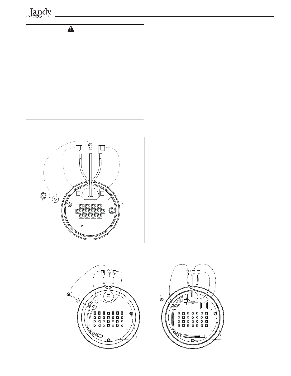
a. 12V Small Light Engine (PCB) Replacement
1. Remove two (2) nuts and two (2) washers.
2. Unplug the quick disconnect terminals from the
light engine.
3. Remove the light engine from the light fixture.
4. Place new light engine into the fixture with
the
orientation shown in Figure 7.
5 Secure the light engine with one (1) nylon washer
and one (1) nut. Torque to 12 in-lbs.
6. Place a nylon washer on the other stud and place
the green ground wire terminal on the nylon
washer and secure both with the nut. Torque to
12 in-lbs.
6.2 To Reset to the Beginning of the
Color Sequence
Turn the light OFF, wait four (4) to fi ve (5) seconds,
then turn ON, the light will return to the beginning of
the color cycle (Alpine White).
NOTE If an AquaLink RS control system is being used
the color set can be selected using the indoor
controller.
NOTE
To synchronize colors on multiple Jandy
WaterColors Light systems wired to separate
switches, perform the above actions on
all of their switches simultaneously. All
Jandy WaterColors Lights will synchronize
automatically if activated by the same switch.
No other accessories are required.
Section 7. Replacing Light Engine
(PCB)
WARNING
Always disconnect power to the color light at the
circuit breaker before servicing the light. Failure to do
so could result in death or serious injury to installer,
serviceman, pool or spa users or others due to
electrical shock.
1. Turn off the main electrical switch or circuit
breaker, as well as the switch, which operates the
underwater light.
2. Be sure to have the following items:
• A new lens gasket, P/N R0451101 for the large
light or P/N R0400501 for the small light.
• A light engine. See Table 2 for specifi cation.
Table 2. Light Specifi cations
Model Fixture
Voltage
Jandy WaterColors
Large Light
Jandy WaterColors
Large Light
Jandy WaterColors
Small Light
Jandy WaterColors
Small Light
12 Volt AC R0474000
120 Volt AC R0474100
12 Volt AC R0473900
120 Volt AC R0473900
Light Engine (PCB)
Part Number
WARNING
Be sure to keep the special pilot screw from this
underwater light. This screw mounts and electrically
grounds the housing securely to the mounting ring
and wet niche. Failure to use the screw provided
could create an electrical hazard, which could result
in death or serious injury to pool or spa users,
installers or others due to electrical shock.
4. Pool Clamp Removal.
a. Loosen the Phillips head screws (six (6) for small
light, eight (8) for large light) to allow the bottom
clamp to be removed from the face ring assembly.
Do not remove the screws or the retaining rings.
The retaining rings prevent the screws from falling
free from the bottom clamp and also aid in ease of
assembly.
b. Remove the bottom clamp, the face ring assembly,
the glass lens, and the gasket from the fixture.
Remove the gasket from the lens. Refer to
9, Exploded View and Replacement Parts..
Section
5. Light Engine Replacement
a. 12V Small Light Engine (PCB) Replacement
WARNING
Replace light engine with the same type. Failure
to replace the light engine with the same type will
damage the light assembly and may cause an
electrical hazard resulting in death or serious injury
to pool or spa users, installers, or others due to
electrical shock, and may also cause damage to
property. Be sure the power is switched OFF before
removing or installing PCB. Allow PCB to cool before
replacing.
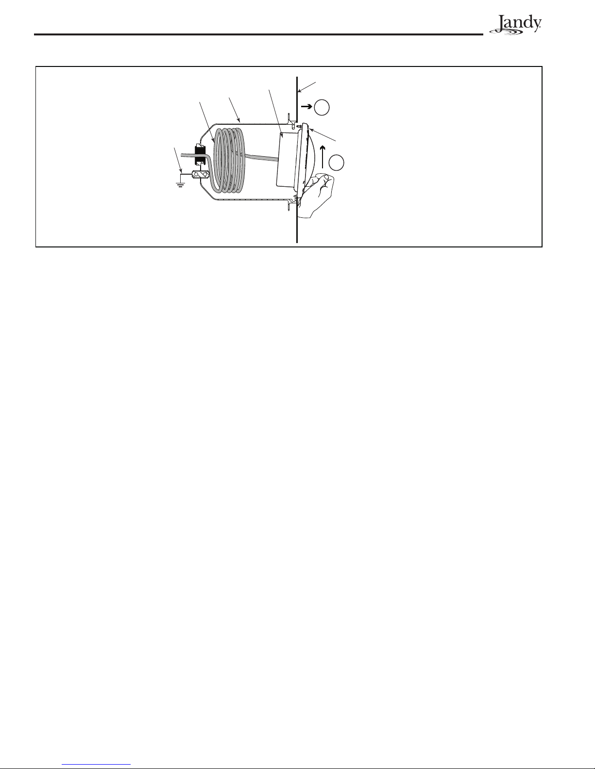
3. To remove the light assembly, unscrew the special
pilot screw at the top of the face ring, remove light
assembly from niche and gently place assembly
on the deck. It is not necessary to drain down the
pool. See Figure 6.
1. Remove two (2) nuts and two (2) washers.
2. Unplug the quick disconnect terminals from the
light engine.
3. Remove the light engine from the light fixture.
4. Place new light engine into the fixture with
orientation shown in Figure 7.
5 Secure the light engine with one (1) nylon washer
and one (1) nut. Torque to 12 in-lbs.
6. Place a nylon washer on the other stud and place
the green ground wire terminal on the nylon
washer and secure both with the nut. Torque to
12 in-lbs.
the
Page 12
Page 12
7. Plug in the quick disconnect wire (white for the
12V and red for the 120V) onto the terminal
(AC1) of the light engine.
8. Plug in the quick disconnect wire (black for the
12V and blue for the 120V) onto terminal (AC2)
of the light engine.
b. Large Light Engine (PCB) Replacement (120V
and 12V)
1. Remove three (3) nuts and washers.
2. Unplug the quick disconnect terminals from the
PCB.
3. Remove the light engine from the light fixture.
4. Place new light engine into the fixture with the
orientation shown in Figure 8.
5 Secure the new light engine (PCB) with two (2)
nylon washers and two (2) nuts. Torque to
12 in-lbs.
6. Plug in the white quick disconnect wire onto the
terminal (J2) of the light engine.
7. Plug in black quick disconnect wire onto terminal
(J6) of the light engine for the 12V models;
or terminal (J3) of the light engine for 120V
models.
8a. For 12V models, place a nylon washer on the
stud and place the green ground wire terminal on
the nylon washer and secure both with the nut.
Torque to 12 in-lbs.
8b. For 120V models, place the green ground wire
on the stud and secure with the nut. Torque to 12
in-lbs.
a. If not already done, remove the gasket from the
glass lens and install a new gasket, P/N R0451101
for the large light and R0400501 for the small
light, on the lens. On the small light, remove the
diverger from the lens.
POOL LIGHT
Power
Cord
Bonding
cable
Figure 6. Removing the Jandy WaterColors Light Assembly for Light Engine Replacement
7. Plug in the quick disconnect wire (white for the
12V and red for the 120V) onto the terminal
(AC1) of the light engine.
8. Plug in the quick disconnect wire (black for the
12V and blue for the 120V) onto terminal (AC2)
of the light engine.
b. Large Light Engine (PCB) Replacement (120V
and 12V)
Niche
ASSEMBLY
POOL WALL
Unscrew pilot screw
and pull top of light
1
assembly away from
pool wall
PILOT SCREW
2
Push up on
bottom of
light assembly
8a. For 12V models, place a nylon washer on the
stud and place the green ground wire terminal on
the nylon washer and secure both with the nut.
Torque to 12 in-lbs.
8b. For 120V models, place the green ground wire
on the stud and secure with the nut. Torque to 12
in-lbs.
Power
Cord
Bonding
cable
6. Reassemble the fi xture.
SPA LIGHT
ASSEMBLY
Niche
1. Remove three (3) nuts and washers.
2. Unplug the quick disconnect terminals from the
PCB.
3. Remove the light engine from the light fixture.
4. Place new light engine into the fixture with the
orientation shown in Figure 8.
5 Secure the new light engine (PCB) with two (2)
nylon washers and two (2) nuts. Torque to
12 in-lbs.
6. Plug in the white quick disconnect wire onto the
terminal (J2) of the light engine.
7. Plug in black quick disconnect wire onto terminal
(J6) of the light engine for the 12V models;
or terminal (J3) of the light engine for 120V
models.
a. If not already done, remove the gasket from the
glass lens and install a new gasket, P/N R0451101
for the large light and R0400501 for the small
light, on the lens. On the small light, remove the
diverger from the lens.
NOTE A new lens gasket must be used each time the
light is reassembled.
Page 13
WARNING
b. While holding the fixture upright, place the glass
lens with the gasket on top of the fixture. Please
note that the lens gasket is not symmetrical.
Therefore, it must be installed correctly so that
the lens can seal to the fixture housing. Place the
gasket on the lens so that the thick molded side
of the gasket will mate with the housing when the
lens is installed.
See Figure 10. On the small light,
replace the diverger by tucking the tabs between
the lens and gasket.
c. Position the lens and gasket on the fixture. Place
the face ring assembly over the lens and align the
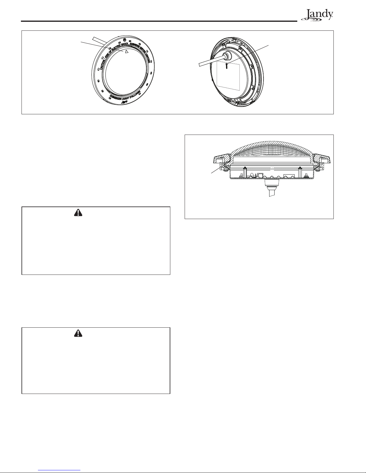
pilot screw with the small arrow mark on the face
of the lens. Note that the small arrow mark on the
face of the lens and the pilot screw of the face ring
must be aligned with the arrow located on fixture
label that reads, “Arrow on this label must line up
with the pilot screw on the Face Ring”. See
Figure 9.
d. While holding the aligned face ring assembly and
fixture together, turn the assembly upside down
and set it on the old gasket, using the old gasket
as an assembly fixture. This will keep the lens and
gasket assembly from being pushed out of the face
ring while you secure it to the light fixture.
e. Spread the bottom clamp over the electrical cord
and slide it onto the back of fixture to the top
clamp.
f. Tighten the Phillips head screws (eight (8) for
large light and six (6) for small light) on the light
in alternating cross-pattern. Torque screws to
approximately 20 in-lbs. Do not over-tighten.
g. Discard the old gasket.
Risk of Electrical Shock or Electrocution. Always
install a new lens gasket whenever disassembling
the light (Jandy Color Light Gasket P/N R0451101 for
large light and P/N R0400501 for small light). Failure
to do so may permit water to leak into the assembly,
which could cause:
(a) An electrical hazard resulting in death or serious
injury to pool or spa users, installers, or others due to
electrical shock, or
(b) A malfunction of the Jandy WaterColors Light,
which likewise could result in serious injury to pool or
spa users, installers, or bystanders, or in damage to
property.
Green
Black (12V)
Blue (120V)
Light
Engine
Secure
First
Nut
Nylon
Washe r
White (12V)
Red (120V)
AC1 AC2
Page 13
b. While holding the fixture upright, place the glass
lens with the gasket on top of the fixture. Please
note that the lens gasket is not symmetrical.
Therefore, it must be installed correctly so that
the lens can seal to the fixture housing. Place the
gasket on the lens so that the thick molded side
of the gasket will mate with the housing when the
lens is installed.
replace the diverger by tucking the tabs between
the lens and gasket.
NOTE Be sure to face the dull side of the diverger
down towards the PCB.
c. Position the lens and gasket on the fixture. Place
the face ring assembly over the lens and align the
pilot screw with the small arrow mark on the face
of the lens. Note that the small arrow mark on the
face of the lens and the pilot screw of the face ring
must be aligned with the arrow located on fixture
label that reads, “Arrow on this label must line up
with the pilot screw on the Face Ring”. See
Figure 9.
d. While holding the aligned face ring assembly and
fixture together, turn the assembly upside down
and set it on the old gasket, using the old gasket
as an assembly fixture. This will keep the lens and
gasket assembly from being pushed out of the face
ring while you secure it to the light fixture.
e. Spread the bottom clamp over the electrical cord
and slide it onto the back of fixture to the top
clamp.
See Figure 10. On the small light,
f. Tighten the Phillips head screws (eight (8) for
Figure 7. Small Light Engine (PCB) Replacement
and Wiring
Nut
Nylon
Washer
Green
Black
J6
J2
White
Secure
First
g. Discard the old gasket.
Nut
Figure 8. Large Light Engine (PCB) Replacement and Wiring
large light and six (6) for small light) on the light
in alternating cross-pattern. Torque screws to
approximately 20 in-lbs. Do not over-tighten.
White
Green
J3
J2
Black
Secure
First
120V Wiring12V Wiring
Page 14
Page 14
a. Coil the extra four (4) feet of cord around the
fixture or into the base of the niche and place the
light assembly into the niche.
b. Engage the retainer tab on the bottom of the face
ring, then pivot the top of the fixture inward and
tighten the special pilot screw.
Align arrow of the
lens with the pilot
screw
Figure 9. Alignment of the Lens, Face Ring, Housing and Clamps for WaterColors Lights
Align pilot screw with
the arrow located on
the fi xture label
7. Reinstall the Jandy Light into niche fi xture.
a. Coil the extra four (4) feet of cord around the
fixture or into the base of the niche and place the
light assembly into the niche.
b. Engage the retainer tab on the bottom of the face
ring, then pivot the top of the fixture inward and
tighten the special pilot screw.
Thick molded
side of the
gasket must
mate with
the body of
the housing
WARNING
Use only the special pilot screw provided with this
underwater light. This screw mounts and electrically
grounds the housing securely to the mounting ring
and wet niche. Failure to use the screw provided
could create an electrical hazard, which could result
in death or serious injury to pool or spa users,
installers or others due to electrical shock.
Figure 10. Cross Section of Jandy WaterColors LED
Light
Section 8. Twelve (12) Volt
Installation
A separate 12-Volt AC Transformer is required on all
8. If pool is empty, fi ll the pool until the underwater
light is completely submerged in water before
12-Volt Models. For Jandy WaterColors Light use a
150-watt multi-tap 12-volt system per light.
operating the light for more than 10 seconds. Turn
on main switch or circuit breaker, as well as the
switch, which specifi cally operates the underwater
light, to check for proper operation.
WARNING
Never operate this underwater light for more than
10 seconds unless it is totally submerged in water.
Without total submersion, the light assembly will get
extremely hot, which may result in serious burns or in
damage to the light. This may result in serious injury
to pool or spa users, installers, or bystanders or in
damage to property.
NOTE For optimum performance Jandy recommends
to use one transformer per 12-volt light.
To ensure maximum safety, it is strongly recommended
that a transformer that has been listed or recognized by
a Nationally Recognized Testing Laboratory (NRTL) for
the application be used.
Page 15
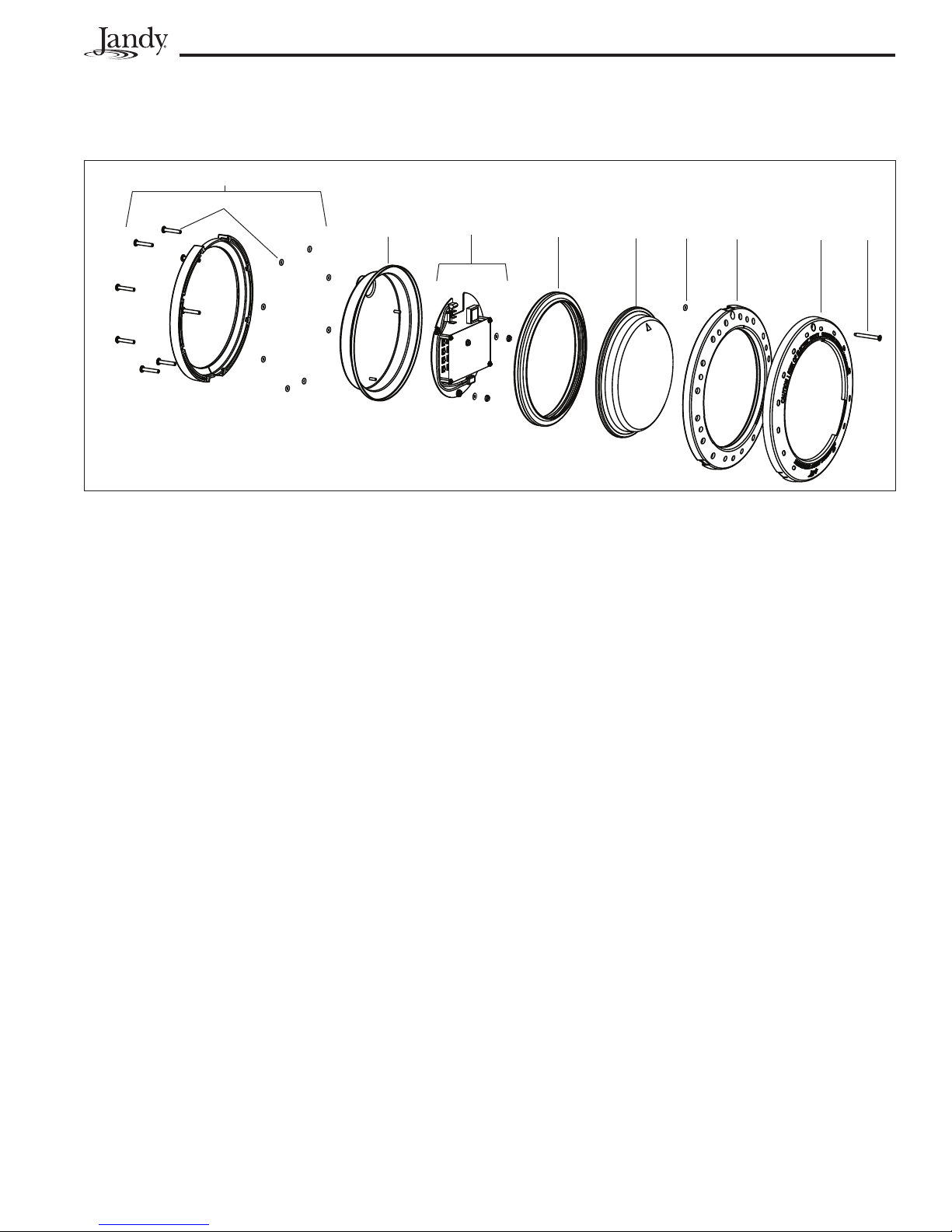
Section 9. Exploded View and Replacement Parts
9.1 Jandy Large WaterColors LED Light
5
8
12
35467
Page 15
7
Figure 11. Jandy Large WaterColors LED Light Exploded View
DWG # Part # Description Field Replaceable
1 N/A WaterColors Light Housing NO - Purchase New Light
2 R0474000 Light Engine PCB, 12V Large LED Light w/ Light Shaping Diverger YES
2 R0474100 Light Engine PCB, 120V Large LED Light W/ Light Shaping Diverger YES
3 R0451101 Silicone Gasket YES
4 R0450601 Glass Lens YES
5 R0450701 Clamp Assembly YES
6 R0450801 Face Ring, Stainless Steel (SS) YES
6 R0450802 Face Ring, Plastic, Whitet YES
6 R0450803 Face Ring, Plastic, Black YES
6 R0450804 Face Ring, Plastic, Gray YES
6 R0450805 Face Ring, Plastic Set YES
7 R0450901 Pilot Screw, with Retainer YES
8 R0451001 Clamp Screws (8 Screws and 8 Retainers) YES
Page 16
Page 16
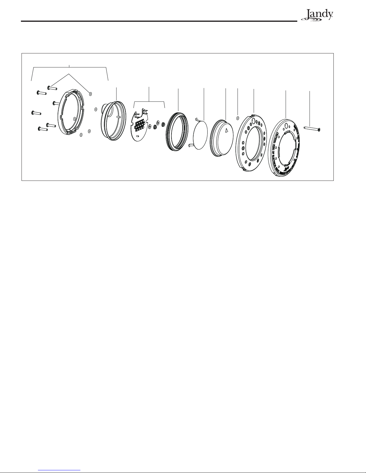
9.2 Jandy Small WaterColors LED Light
7
9
12
4
3
8
5
6
7
8
Figure 12. Jandy Small WaterColors LED Light Exploded View
DWG # Part # Description Field Replaceable
1 N/A WaterColors Light Housing NO - Purchase New Light
2 R0473900 Light Engine, 12V/120V Small LED Light YES
3 R0474200 Diverger, Light Shaping, Small LED Light YES
4 R0400501 Silicone Gasket YES
5 R0400601 Glass Lens YES
6 R0451201 Clamp Assembly YES
7 R0451301 Face Ring, Stainless Steel (SS) YES
7 R0451302 Face Ring, Plastic, White YES
7 R0451303 Face Ring, Plastic, Black YES
7 R0451304 Face Ring, Plastic, Gray YES
7 R0451305 Face Ring, Plastic Set YES
8 R0450901 Pilot Screw, with Retainer YES
9 R0451401 Clamp Screws (6 Screws and 6 Retainers) YES
Page 17

Notes
Page 17
Page 18

Page 18
Notes
Page 19

Notes
Page 19
Page 20

LIMITED WARRANTY
Thank you for purchasing Jandy pool and spa products. Jandy Pool Products, Inc. warrants all parts to be free
from manufacturing defects in materials and workmanship for a period of one (1) year from the date of retail
purchase, with the following exceptions:
®
AquaLink
•
Never Lube
•
AquaPure Electronic Chlorine Generator Electrolytic Cells carry a five (5) year limited warranty on a prorated basis.
•
RS units installed with Jandy Surge Protection Kits will be covered for two (2) years.
®
valves are warranted for the life of pool and/or spa on which they were originally installed.
®
This warranty is limited to the first retail purchaser, is not transferable, and does not apply to products that have
been moved from their original installation sites. The liability of Jandy Pool Products, Inc. shall not exceed the
repair or replacement of defective parts and does not include any costs for labor to remove and reinstall the
defective part, transportation to or from the factory, and any other materials required to make the repair. This
warranty does not cover failures or malfunctions resulting from the following:
1. Failure to properly install, operate or maintain the product(s) in accordance with our published Installation,
Operation and Maintenance Manuals provided with the product(s).
2. The workmanship of any installer of the product(s).
3. Not maintaining a proper chemical balance in your pool and/or spa [pH level between 7.2 and 7.8, Total
Alkalinity (TA) between 80 to 120 ppm, Total Dissolved Solids (TDS) less than 2000 not including salt ppm].
4. Abuse, alteration, accident, fire, flood, lightning, rodents, insects, negligence or acts of God.
5. Scaling, freezing, or other conditions causing inadequate water circulation.
6. Operating the product(s) at water flow rates outside the published minimum and maximum specifications.
7. Use of non-factory authorized parts or accessories in conjunction with the product(s).
8. Chemical contamination of combustion air or improper use of sanitizing chemicals, such as introducing
sanitizing chemicals upstream of the heater and cleaner hose or through the skimmer.
9. Overheating; incorrect wire runs; improper electrical supply; collateral damage caused by failure of O-Rings,
DE grids, or cartridge elements; or damage caused by running the pump with insufficient quantities of water.
®
LIMITATION OF LIABILITY:
This is the only warranty given by Jandy Pool Products, Inc. No one is authorized to make any other warranties
on behalf of Jandy Pool Products, Inc. THIS WARRANTY IS IN LIEU OF ALL OTHER WARRANTIES,
EXPRESSED OR IMPLIED, INCLUDING BUT NOT LIMITED TO ANY IMPLIED WARRANTIES OF FITNESS
FOR A PARTICULAR PURPOSE AND MERCHANTABILITY. JANDY POOL PRODUCTS, INC. EXPRESSLY
DISCLAIMS AND EXCLUDE S ANY LIABILITY FOR CONSEQUENTIAL, INCIDENTAL, INDIRECT OR
PUNITIVE DAMAGES FOR BREACH OF ANY EXPRESSED OR IMPLIED WARRANTY. This warranty gives
you specific legal rights. You may also have other rights that vary by state or province.
WARRANTY CLAIMS:
For prompt warranty consideration, contact your dealer and provide the following information: proof of purchase,
model number, serial number and date of installation. The installer will contact the factory for instructions
regarding the claim and to determine the location of the nearest designated service center. If the dealer is not
available, you can locate a service center in your area by visiting www.jandy.com or by calling our technical
support department at (707) 776-8200 extensio n 260. All returned parts must have a Returned Material
Authorization number to be evaluated under the terms of this warranty.
Jandy Pool Products, Inc.
H0305500A
6000 Condor Drive, Moorpark, CA, USA 93021 • 707.776.8200 FAX 707.763.7785
For technical support call 707-776-8200, ext. 260
Litho in U.S.A. © 2008 Jandy Pool Products, Inc. 0802
 Loading...