

Page 1

Page 2
ii Contents
Operating Manual HUB24 Series Dimmer
EMC COMPLIANCE
This product is approved for use in Europe and Australia / New Zealand and conforms to the following standards:
European Norms Australian / New Zealand
Standards
EN 50081-1 AS/NZS 4252.1
EN 50082-1 AS/NZS 4251.1
EN 60065 AS/NZS 3260
To ensure continued compliance with EMC Directive 89/336 and the Australian Radiocommunications Act 1992, use
only high quality data cables with continuous shield, and connectors with conductive backshells. Examples of such
cables are:
DMX: Belden 8102 100% Aluminium foil screen, 65% Copper braid.
JANDS ELECTRONICS PTY LTD 2002
All rights reserved
DISCLAIMER
Information contained in this manual is subject to change without notice and does not
represent a commitment on the part of the vendor. JANDS ELECTRONICS Pty Ltd
shall not be liable for any loss or damage whatsoever arising from the use of
information or any error contained in this manual.
It is recommended that all service and repairs on this product be carried out by JANDS
ELECTRONICS Pty Ltd or its authorised service agents.
JANDS HUB24 Series dimmers must only be used for the purpose they were intended
by the manufacturer and in conjunction with this operating manual.
JANDS ELECTRONICS Pty Ltd cannot accept any liability whatsoever for any loss or
damage caused by service, maintenance or repair by unauthorised personnel, or by use
other than that intended by the manufacturer.
Disconnect power when not in use.
Manufactured in Australia by:
JANDS ELECTRONICS PTY LTD ACN 001 187 837
40 KENT RD
Locked Bag 15
MASCOT NSW 2020
AUSTRALIA
PHONE: +61-2-9582-0909
FAX: +61-2-9582-0999
EMAIL: jandsinfo@jands.com.au
WEB: www.jands.com.au
Page 3

Contents iii
Revision 1.0 - 7-May-02 HUB24 Series Dimmer Operating Manual
Table of Contents
1 Introduction .......................................................................1
2 Equipment Description.....................................................3
3 Getting Started ..................................................................4
3.1 Positioning the Unit..........................................................................................4
3.2 Connecting power.............................................................................................4
3.3 Set DMX start channel .....................................................................................4
3.4 Connecting loads ..............................................................................................5
3.5 Connecting DMX-512 ......................................................................................5
3.6 Power-up sequence ...........................................................................................5
4 Dimmer Operation.............................................................7
4.1 Main Screen......................................................................................................7
4.2 Menu structure..................................................................................................7
4.2.1 DMX Start Channel (1-1) ......................................................................8
4.2.2 DMX Cross Patch (1-2) .........................................................................9
4.2.3 DMX Terminate (1-3)............................................................................9
4.2.4 Loss of DMX Signal (1-4) .....................................................................9
4.2.5 Output Control Curve (2-1) ...................................................................9
4.2.6 Supply Current Limit (2-2) ..................................................................10
4.2.7 Drive Outputs (3-1)..............................................................................10
4.2.8 Build Outputs (3-2)..............................................................................11
4.2.9 Clear Test (3-3)....................................................................................11
4.2.10 Backlight Activation (4-1-1)................................................................11
4.2.11 Backlight Intensity (4-1-2)...................................................................11
4.2.12 Display Contrast (4-1-3) ......................................................................12
4.2.13 Main Display (4-1-4)............................................................................12
4.2.14 Playback Mode (4-2)............................................................................12
4.2.15 Restore Defaults (4-3)..........................................................................12
4.2.16 Set Time & Date (4-4) .........................................................................13
4.2.17 Fault Detect (4-5).................................................................................13
4.2.18 Software Version (5-1).........................................................................14
4.2.19 Display Mains (5-2) .............................................................................14
4.2.20 Calibrate Voltage (5-3-1).....................................................................14
4.2.21 Calibrate Current (5-3-2) .....................................................................14
4.2.22 Error Log (5-4).....................................................................................15
Page 4

iv Contents
Operating Manual HUB24 Series Dimmer
4.2.23 Clear Error Log (5-5)........................................................................... 15
4.2.24 Control Source (5-6)............................................................................ 15
4.2.25 Record a Snapshot (6-1)...................................................................... 16
4.2.26 Record a Chase (6-2-#-1) .................................................................... 16
4.2.27 Chase Parameters (6-2-#-2)................................................................. 16
4.2.28 Clear a Chase (6-2-#-3) ....................................................................... 17
4.2.29 Playback a Snapshot (7-1)................................................................... 17
4.2.30 Playback a Chase (7-2)........................................................................ 18
4.2.31 Clear Playback (7-3)............................................................................ 18
4.3 Deep clear....................................................................................................... 18
4.4 Download from PC ........................................................................................ 19
5 Fault Diagnosis................................................................20
5.1 Protection....................................................................................................... 20
5.1.1 RCD protection.................................................................................... 20
5.1.2 Output protection................................................................................. 20
5.1.3 Thermal protection .............................................................................. 21
5.1.4 Neutral – Earth voltage........................................................................ 21
5.2 Output faults................................................................................................... 21
5.3 Software exception errors .............................................................................. 21
5.4 DMX faults .................................................................................................... 22
5.5 Phase fault indication..................................................................................... 22
5.6 Cold lamp filaments....................................................................................... 22
5.7 Output minimum loads .................................................................................. 22
5.8 Fault finding guide......................................................................................... 23
6 Installation .......................................................................25
6.1 Free Standing ................................................................................................. 25
6.2 Wall Mounting............................................................................................... 25
7 Maintenance.....................................................................26
8 Technical Data and Specifications................................. 27
8.1 DMX connector pin-outs ............................................................................... 28
8.2 Internal Mains Wiring.................................................................................... 28
8.2.1 Mains Power - Block Diagram............................................................ 29
8.2.2 Mains wiring colour codes .................................................................. 29
8.2.3 Normal Three Phase plus Neutral Operation....................................... 30
8.2.4 Single Phase Operation........................................................................ 30
Page 5

Contents v
Revision 1.0 - 7-May-02 HUB24 Series Dimmer Operating Manual
Appendix A Using the Dimmer Utility..................................31
A.1 Installation......................................................................................................31
A.2 Main Window.................................................................................................32
A.3 File Download utility......................................................................................32
A.4 Curve Editor utility.........................................................................................33
A.5 Logo Generator utility ....................................................................................36
Appendix B PC Download Cable.........................................40
Page 6

vi Contents
Operating Manual HUB24 Series Dimmer
Supplied Items
1. HUB24 Dimmer.
2. User Manual.
3. Warranty Registration Card.
Optional Accessories
• Reinforced Protective Cover (part No. JND-DC-HUB24).
• HUB Download Kit (part No. JND-HUB24DOWNLOAD)
- PC Download cable
- Jands Dimmer Utility software
• Wall mounting bracket (part No. JND-HUB24WMB).
• Hand-Rail Mounting brackets (part No. JND-HUB24HRB).
Page 7

Introduction 1
Revision 1.0 - 7-May-02 HUB24 Series Dimmer Operating Manual
1 Introduction
The JANDS HUB24 is a unique combination of dimmer channels, power distribution
and isolated DMX splitting, all in one compact and low noise package. The HUB24 is
specifically designed for demanding touring and theatre applications and is ideal for
shows where a mixture of conventional and automated lights are used.
Especially suitable for live shows, school auditoriums, trade shows and other similar
applications, the HUB24 eliminates the usual clutter associated with dimmer racks,
power distribution boxes and DMX splitters. The HUB24 also includes the ability to
record and playback snapshots and chases without a lighting console.
One HUB24 incorporates:
– 15 Dimmer outputs
– 9 Power Distribution outputs
– 1 in 2 out opto-isolated DMX splitter
HUB24 dimmers use a chokeless IGBT output topology for reduced weight and low
acoustic noise. The unit is primarily cooled by natural convection; small fans will turn
on only in extreme circumstances.
The unit monitors the supply current drawn on each phase. If more than a preset limit is
drawn from a phase, all the dimmer outputs on that phase are dimmed down until the
current is near to the limit. This ensures connector and upstream circuit breaker current
ratings are not exceeded for long periods of time.
The HUB24 features microprocessor-based digital control. A menu-driven user
interface, consisting of only two buttons, an encoder wheel and a large graphics LCD,
enables the user to easily monitor and select all the built-in functions.
The user has the ability to soft patch the channels out of sequence, test selected channels
while the remainder of the dimmer stays on-line, download custom dimming curves,
capture or build up to eight non-volatile snapshots and chases.
Other functions provided are dimmer “soft” start, bad (soft) neutral detection,
monitoring supply voltage, current and other working parameters of the unit.
Control signal connection to the HUB24 is via a standard DMX-512 socket located on
the front panel along with DMX through and two opto-isolated DMX outputs. Also
located on the front panel are the dimmer and distribution output sockets. The three
phase power entry and a cable tray are located on the rear panel.
The unit will “wake-up” in the mode it was last programmed to run - an ideal function
for stand alone applications. If no particular mode has been previously defined, the unit
looks for DMX control. The user has the ability to set how the HUB24 will respond if
DMX control is lost, but in all cases the dimmer outputs will turn off if the DMX signal
is not restored within 10 minutes.
The HUB24 range of dimmers have been designed to receive future optional software
upgrades to the operating system, without opening the unit.
The HUB24 is convenient to transport due to its solid carry handles, protective
transportation bag and built-in cable tray for storage of the three phase cable.
An optional wall bracket allows the HUB24 to be wall-mounted and optional hand-rail
mounting brackets allow the HUB24 to be mounted on a catwalk rail.
Page 8
2 Equipment Description
Operating Manual HUB24 Series Dimmer
Figure 2.1
Page 9

Equipment Description 3
Revision 1.0 - 7-May-02 HUB24 Series Dimmer Operating Manual
2 Equipment Description
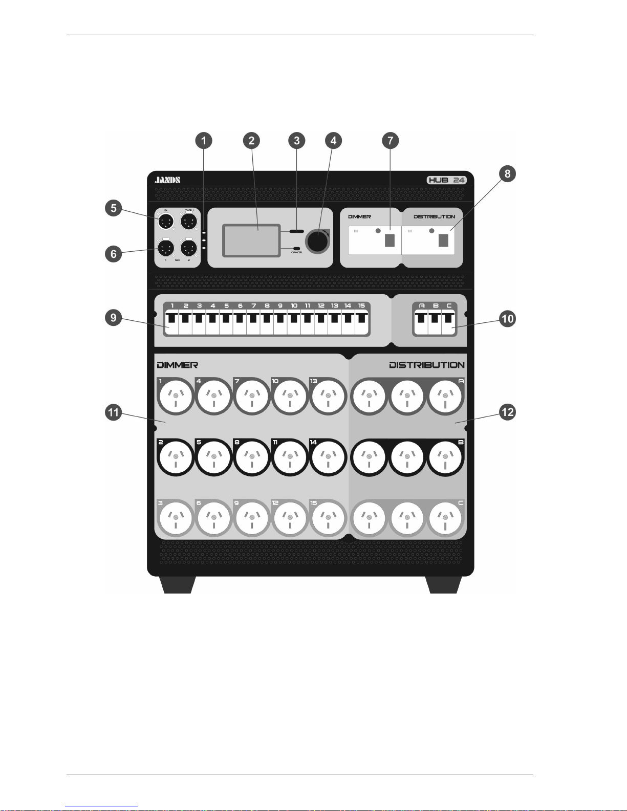
Front panel layout
Figure 2.1
1. Phase Power LEDs: Three different coloured LEDs (one for each phase) indicate
that the mains supply phases are available. Red for phase A, White for phase B and
Blue for phase C.
2. Display: Large graphics LCD, used to display dimmer status information and to
control the menus.
3. Menu buttons: 2 buttons are used to navigate the menus and save changes.
4. Encoder wheel: This detent action control knob is used to select items from the
menus and to select the channel levels or chase rate (depending on the operating
mode).
5. DMX IN/THRU connectors: A standard five pin AXR connector receives DMX-
512 signals from a control source and a second “Thru” connector links signal to
other DMX equipment. See section 8.1 for wiring details.
6. DMX OPTO-OUT connectors: Two fully isolated DMX outputs, using standard
five pin AXR connectors. See section 8.1 for wiring details.
7. Dimmer RCD protection: A three phase RCD protects the dimmer outputs. It
must not be used as load break switch.
8. Distribution RCD protection: A three phase RCD protects the power distribution
outputs. It must not be used as load break switch.
9. Dimmer circuit breakers: 15 circuit breakers, one for each dimmer output.
10. Distribution circuit breakers: 3 circuit breakers, each one supplies a row of 3
separate distribution outputs.
11. Dimmer Output connectors: 15 dimmer output sockets.
12. Distribution Output connectors: 9 distribution output sockets.
Page 10

4 Getting Started
Operating Manual HUB24 Series Dimmer
3 Getting Started
3.1 Positioning the Unit
Correct positioning and adequate ventilation are essential for reliable operation. Ensure
the transportation bag or road case is totally removed before use. The HUB24 must be
upright when in use, with clearances of 100mm behind, 200mm above and 100mm on
each side. The unit’s feet provide air intakes (front, back & 2 sides), these openings
must not be obstructed.
See section 6.2 for wall mounting details. See your Jands distributor for other mounting
options.
3.2 Connecting power
The three phase cable must be completely removed from the cable tray before applying
power to the unit.
The mains supply to the HUB24 dimmers must be protected by upstream circuit
breakers or fuses (see sections 8.2.3 & 8.2.4). If the supply cable is damaged, it must be
replaced with a cable available from JANDS or its service agents.
The power plug must be connected to an appropriately rated socket outlet. The plug’s
retaining lock ring (if present) must be screwed home.
WARNING
DAMAGE MAY OCCUR IF THE RETAINING LOCK RING IS NOT
PROPERLY SECURED.
Ensure adequate mains socket access once the dimmer is installed, to allow for
switching the HUB24 on and off.
Turn on the power and check that the three PHASE indicator LEDs are on. Check the
large display is on and not showing any faults before connecting any loads. If the
PHASE LEDs or the display indicate a fault condition, power down and remedy the
fault before trying again. See section 5.5 regarding phase faults.
3.3 Set DMX start channel
The HUB24’s dimmer outputs respond to 15 DMX channels. The first channel can be
set anywhere from channel 1 to channel 512, the remaining channels will follow in
sequence.
• At the main screen (see section 4.1) press the large button 3 times
(to select
Menu1 DMX Settings1-1 Start Channel ).
• Turn the encoder wheel to change the displayed DMX channel.
• Press the large button (now shown as OK) to save the new start channel.
See section 4.2.2 if the dimmer outputs need to respond to out of sequence DMX
channels.
Page 11

Getting Started 5
Revision 1.0 - 7-May-02 HUB24 Series Dimmer Operating Manual
3.4 Connecting loads
Power down the HUB24.
Plug in the loads to the Dimmer output sockets. It is recommended that, where practical,
the load on the dimmer outputs be evenly spread across the 15 channels. This will
minimise fan noise and make it harder to overload a single phase.
Ensure the load on each dimmer output is greater than the minimum (see section 5.7).
Plug in the loads to the Distribution output sockets. Each output must not be loaded
beyond the capacity of its socket.
3.5 Connecting DMX-512
The dimmer input signal should conform to the USITT DMX-512 (1990) specification.
See section 8.1 for connector wiring details.
The status of the DMX signal is indicated on the bottom of the display.
The DMX input to the HUB24 dimmers connects to the IN socket on the front panel.
The DMX signal may be daisy-chained to the next dimmer via the THRU socket. If the
THRU socket is not being used see section 4.2.3 for how to terminate the DMX
segment.
The two ISO sockets may be used to start two new fully isolated DMX segments, which
may be required for:
• Isolating DMX segments that run to equipment that is powered from different
supplies.
• Star DMX network topology.
• Amplifying the DMX signal for extremely long cable runs.
• Driving more than the normal maximum of 32 devices from a console.
3.6 Power-up sequence
When powering up, the following sequence should be used:
1. Power up the control desk.
2. Power up any softpatches and/or DMX receivers.
3. Ensure the dimmer RCDs and circuit breakers are switched on.
4. Power up the dimmers last, preferably one at a time starting from the first
dimmer rack in the DMX loop.
This procedure minimises the risk of lamps and fixtures responding to any false DMX
data produced by control desks or ancillary equipment at turn-on (producing the lighting
equivalent of an audio “thump”) and prevents damage to lamps, dimmers, and other
controlled devices.
Use the reverse procedure when powering down.
Page 12
6 Dimmer Operation
Operating Manual HUB24 Series Dimmer
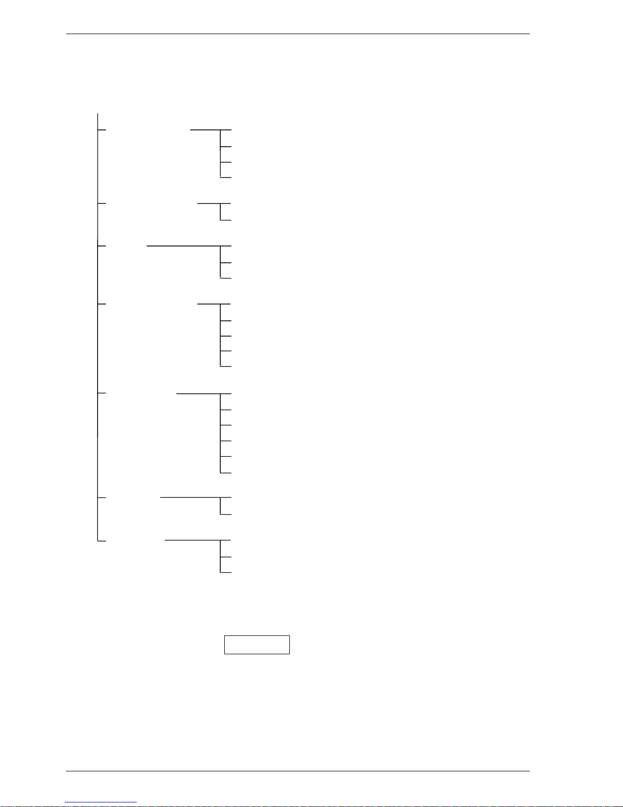
Menu Structure Overview
MENU
1 DMX Settings 1-1 Start Channel
1-2 Cross Patch (for each output)
1-3 DMX Terminate
1-4 Loss of Signal
2 Dimmer Output 2-1 Control Curve (for each output)
2-2 Current Limit
3 Test 3-1 Drive Output (for individual, phase or all outputs)
3-2 Build Output (for individual, phase or all outputs)
3-3 Clear Test
4 System Settings 4-1 Display (backlight, contrast, main display)
4-2 Playback Mode
4-3 Restore Defaults
4-4 Time & Date
4-5 Fault Detect
5 Diagnostics 5-1 Software Version
5-2 Display Mains (voltage, current & frequency)
5-3 Calibrate (mains voltage & current)
5-4 Error Log (last 15 entries)
5-5 Clear Error Log
5-6 Control Source (for each output)
6 Record 6-1 Snapshot (8x snapshots)
6-2 Chase (8x chases)
7 Playback 7-1 Snapshot
7-2 Chase
7-3 Clear Playback
Figure 4.1
Page 13
Dimmer Operation 7
Revision 1.0 - 7-May-02 HUB24 Series Dimmer Operating Manual
4 Dimmer Operation
This section assumes the dimmer has been correctly connected to three phase power and
a source of DMX input signal, as described in section 3.
In this manual, references to individual front panel buttons will be in uppercase bold
text, eg. CANCEL, while references to display messages will be in quotation marks,
eg. “Test”.
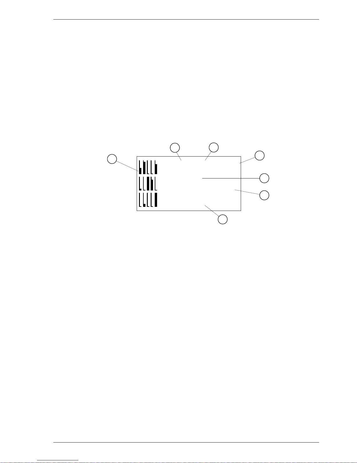
4.1 Main Screen
The Main Screen is the screen that is displayed when the menu is not being used and no
errors or warnings are indicated. See section 4.2.12 for details of changing the contents
of the main screen.
Main Screen (normal)
7
-DMXOK-
TERMINATED
Menu
100
14:39
PLAYBACK / BUILD
6
4
5
3
1
2
Information displayed on the normal main screen:
1. Bar graph mimic of the actual control level of each dimmer output, before the
control curve is applied (from all sources: DMX, playback & test).
2. ‘Playback’ is displayed when Snapshots and Chases are being played back on one or
more channels.
3. ‘Build’ is displayed when Test Build has control of one or more channels.
4. Function of the large button (see section 4.2).
5. DMX address of the 1st dimmer channel.
6. Present time (24hr format).
7. Status of the DMX input signal & termination.
4.2 Menu structure
All the functions and settings of the HUB24 are accessed through a menu. An overview
(first two levels) of this menu structure is shown in figure 4.1. Except where noted, the
menu will automatically return to the main screen after 20 seconds of no button presses
or encoder wheel movements.
The menu uses a “tree” structure, consisting of multiple levels of sub-menus with the
main screen being the start of the tree. Navigation of the menu entails highlighting a
sub-menu using the encoder wheel and pressing the large button to move to the
highlighted sub-menu level. The encoder wheel is then used to highlight the next submenu, the large button is pressed again to move to another level, and so on.
Page 14

8 Dimmer Operation
Operating Manual HUB24 Series Dimmer
A typical menu screen
Select
4
3
21
Ch1-Next
All
Phase A
Phase B
Information displayed on a menu:
1. Numbering showing the current location within the menu tree.
2. Tabs showing the number of items in this sub-menu with current position
highlighted.
3. Function of the large button (see below).
4. Highlighted menu item.
The large button performs different functions depending on the current sub-menu. The
button’s label is always shown in the top right hand corner of the display.
The various functions of the large button are:
MENU enters the first level of the menu tree
SELECT moves into the highlighted menu item
OK saves the new value and exits the current screen
NEXT jumps to the next channel or item
RECORD record a snapshot or chase step
CONFIRM perform the displayed action
The CANCEL button is always used to move back from a sub-menu to the previous
menu level. This button will exit a screen without saving changes. Pressing CANCEL
five times will return to the main screen from anywhere in the menu tree.
4.2.1 DMX Start Channel (1-1)
Menu1 DMX Settings1-1 Start Channel
The HUB24’s dimmer outputs can be set to respond to 15 consecutive DMX
channels, the first channel can be set anywhere from 1 to 512. By setting the start
channel to 1, the dimmer will respond to DMX channels 1 through 15 inclusive.
When using racks of looped dimmers, the next dimmer should start at channel 16, the
one after that at channel 31, and so on.
• Select “1-1 Start Channel” on the menu.
• Turn the encoder wheel to change the displayed start channel.
• Press OK to save the new start channel and exit.
Note: If the start channel is set above 498, the dimmer outputs that would have been
above 512 will be set to not connected and not respond to the DMX signal.
Page 15

Dimmer Operation 9
Revision 1.0 - 7-May-02 HUB24 Series Dimmer Operating Manual
4.2.2 DMX Cross Patch (1-2)
Menu1 DMX Settings
1-2 Cross Patch
Each of the HUB24’s dimmer outputs can be set to individually respond to any DMX
channel, from 1 to 512. This allows the outputs to be patched out of sequence.
• Select “1-2 Cross Patch” on the menu.
• Turn the encoder wheel to highlight a dimmer output and press SELECT.
• Turn the encoder wheel to changed the displayed DMX channel.
• Press OK to save the new DMX channel and exit.
• Repeat for each dimmer output.
Note: Setting a dimmer output to ‘NC’ means t hat output will ignore the DMX.
4.2.3 DMX Terminate (1-3)
Menu1 DMX Settings
1-3 DMX Terminate
The HUB24 has an internal DMX termination function. The last device in the DMX
line (ie. With its DMX Thru connector not used) should have the DMX terminate
turned on.
• Select “1-3 DMX Terminate” on the menu
• Turn the encoder wheel to highlight either “Terminate” or “Continue”.
• Press OK to save the new termination setting and exit.
Note: Termination does not apply to the opto-isolated DMX outputs.
4.2.4 Loss of DMX Signal (1-4)
Menu1 DMX Settings
1-4 Loss of Signal
If the DMX control signal is lost, there are options on how the HUB24 will respond,
but in all cases the dimmer outputs will turn off if the DMX signal is not restored
within 10 minutes.
• Select “1-4 Loss of Signal” on the menu.
• Turn the encoder wheel to highlight either “Hold”, “Fade to 0” or
“Fade to Snap 1”.
• Press OK to save the new signal loss setting and exit.
4.2.5 Output Control Curve (2-1)
Menu2 Dimmer Output
2-1 Control Curve
The HUB24 contains four control curves, which can be assigned to each dimmer
output individually. The two preset curves are Linear Power and Switched, while the
remaining two are user definable.
The linear power curve gives even fade characteristics for lamps. The switched curve
may be used for controlling devices that should not be dimmed (eg. strobes, motors,
foggers, etc).
Page 16

10 Dimmer Operation
Operating Manual HUB24 Series Dimmer
The user definable curves can be used for lamps whose light output is not linear, for
lamps with special requirements (eg. fluorescent tubes) or if any special curve is
required.
The user definable curves are created and edited on a PC (or Laptop) using Jands
Dimmer Utility software and downloaded to the dimmer. See appendix A for how to
use the Dimmer Utility software and see section 4.4 on how to download the curves
to the HUB24.
• Select “2-1 Control Curve” on the menu.
• Turn the encoder wheel to highlight a dimmer output and press SELECT.
• Turn the encoder wheel to highlight one of the four control curves.
• Press OK to apply the new curve to the dimmer output and exit.
• Repeat for each dimmer output.
4.2.6 Supply Current Limit (2-2)
Menu2 Dimmer Output
2-2 Current Limit
The HUB24 constantly monitors the supply current, in each phase, consumed by both
the dimmer and distribution outputs. If more than a preset limit is drawn from a
phase, all the dimmer outputs on that phase are dimmed down until the current drops
to near the preset limit.
• Select “2-2 Current Limit” on the menu.
• Turn the encoder wheel to highlight “32A” or “40A” or “50A” or
“63A” or “No limit”.
• Press OK to save the new current limit and exit.
4.2.7 Drive Outputs (3-1)
Menu3 Test
3-1 Drive Output
Drive output allows testing of each dimmer output from the menu, with or without a
console present. A single output, all 5 outputs on a phase or all 15 outputs can
temporarily be faded from 0% to 100%. After testing, each dimmer output returns to
its previous level.
Note: The drive output menus do not timeout and return to the main screen.
Single Output
• Select “3-1 Drive Output” on the menu.
• Ensure “Ch 1 - Next” is highlighted and press SELECT.
• The present drive level of the selected output will be displayed as a percentage.
Turn the encoder wheel to change this output level.
• Press NEXT to control to the next output, the previous output will revert back to
its original level. Repeat the previous step for the new output.
Note: Pressing NEXT when driving Ch 15 will jump back to Ch 1.
• Press CANCEL at any time to exit, all outputs revert back to original levels.
Page 17

Dimmer Operation 11
Revision 1.0 - 7-May-02 HUB24 Series Dimmer Operating Manual
Single Phase or All Outputs
• Select “3-1 Drive Output” on the menu.
• Turn the encoder wheel to highlight either “All”, “Phase A”, “Phase B” or
“Phase C” and press SELECT.
• All the selected outputs will be set to zero. Turn the encoder wheel to directly
change the drive level of all the selected outputs.
• Press CANCEL to exit, all outputs will revert back to their original levels.
4.2.8 Build Outputs (3-2)
Menu3 Test
3-2 Build Output
The build output menu operates in the same way as drive outputs (see 4.2.7) however
the levels are not lost when the menu is exited.
Build output allows the user to take control of the dimmer outputs from the menu.
Individual outputs, all 5 outputs on a phase or all 15 outputs can be faded from 0% to
100% and permanently remain at that level until cleared by the user.
Note: Build outputs does not take control of the output(s) until the encoder wheel
has been moved.
4.2.9 Clear Test (3-3)
Menu3 Test
3-3 Clear Test
Clear Test allows restoring of DMX control to the outputs that were being controlled
by Test Build outputs.
• Select “3-3 Clear Test” on the menu.
• Press CONFIRM to release all outputs from Build control and exit.
4.2.10 Backlight Activation (4-1-1)
Menu4 System Settings
4-1 Display4-1-1 Backlight Activation
The liquid crystal display has backlighting to enable it to be read in the dark. This
backlight can be set to turn off when the menu is not in use or set to always on.
• Select “4-1-1 Backlight Activation” on the menu.
• Turn the encoder wheel to highlight either “On”, “Auto20secs”or
“Auto5mins”.
• Press OK to save the backlight activation setting and exit.
4.2.11 Backlight Intensity (4-1-2)
Menu4 System Settings
4-1 Display4-1-2 Backlight Intensity
The intensity of the LCD backlight can be changed to suit the ambient light level.
• Select “4-1-2 Backlight Intensity” on the menu.
• Turn the encoder wheel to change the backlight intensity.
• Press OK to save the new backlight intensity and exit.
Page 18

12 Dimmer Operation
Operating Manual HUB24 Series Dimmer
4.2.12 Display Contrast (4-1-3)
Menu4 System Settings4-1 Display4-1-3 Contrast
The contrast of the LCD display can be changed to suit the required viewing angle.
• Select “4-1-3 Contrast” on the menu.
• Turn the encoder wheel to change the contrast level (1 is light, 16 is dark).
• Press OK to save the new contrast and exit.
4.2.13 Main Display (4-1-4)
Menu4 System Settings4-1 Display4-1-4 Main Display
The information that is shown on the main screen can be configured. The options are
Normal, Mains Monitor and Custom Logo. See appendix A for how to create and
edit custom logos on a PC (or Laptop) and see section 4.4 for how to download them
to the HUB24.
The owner’s logo and/or contact details can be shown on the LCD at the main screen.
The logo can be password protected so it can’t be overwritten by somebody hiring the
unit.
• Select “4-1-4 Main Display” on the menu.
• Turn the encoder wheel to highlight either “Normal”, “Mains Monitor” or
“Custom Logo”.
• Press OK to save the new main display setting and exit.
4.2.14 Playback Mode (4-2)
Menu4 System Settings4-2 Playback Mode
When playing back snapshots and chases the HUB24 can also continue to respond to
the incoming DMX signal. How the playback and DMX signal are merged together
can be configured. “Override” ignores the DMX signal, while “HTP” does highest
takes precedence for the level of each channel.
• Select “4-2 Playback Mode” on the menu.
• Turn the encoder wheel to highlight either “Override” or “HTP”.
• Press OK to save the new playback mode and exit.
4.2.15 Restore Defaults (4-3)
Menu4 System Settings4-3 Restore Defaults
• Select “4-3 Restore Defaults” on the menu.
• Press CONFIRM to restore the following settings back to their default values:
− DMX Terminate to Off.
− DMX Loss of signal to Hold.
− Control Curve to Linear for all channels.
− Current Limit to 32 Amps.
− Fault Detect to Detect Faults.
Page 19

Dimmer Operation 13
Revision 1.0 - 7-May-02 HUB24 Series Dimmer Operating Manual
− LCD Contrast and Backlight to defaults.
− Main Screen to Normal.
− Playback Mode to Override.
− Chase parameters to defaults (chase steps are not affected).
Other Settings such as DMX cross patch and the time are not changed.
To ensure all dimmer outputs are restored to DMX control, select “3-3 Clear Test”
and select “7-3 Clear Playback” with “7-3-1 All”.
4.2.16 Set Time & Date (4-4)
The HUB24 has an in-built clock, that keeps track of the time & date, even when the
power is off. The time & date is logged with each entry in the error log.
Menu4 System Settings
4-4Time&Date
• Select “4-4 Time & Date” on the menu.
• Turn the encoder wheel to change the “hours” and press NEXT.
• Turn the encoder wheel to change the “minutes” and press NEXT.
• Turn the encoder wheel to change the “day” and press NEXT.
• Turn the encoder wheel to change the “month” and press NEXT.
• Turn the encoder wheel to change the “year”.
• Press CANCEL to exit .
4.2.17 Fault Detect (4-5)
Menu4 System Settings
4-5 Fault Detect
The HUB24 will detect voltage problems generated by a poor or missing neutral
connection. Normally when a fault is detected, all the dimmer outputs are turned off
and a “Neutral Earth Fault” warning is displayed, until the fault is removed and a
button pressed. See section 5.1.4 for more detail.
In some venues the three phase power supply may be less than ideal, with a “Neutral
Earth Fault” warning occurring without the wiring being truly “faulty”. For this
reason it is possible (but not recommended) to disable the neutral earth fault
detection. ALWAYS check first that the problem is not a dropped neutral in either
the three phase socket or plug and ensure the earth connection is good.
WARNING
IF THE NEUTRAL EARTH FAULT DETECTION IS DISABLED,
UNSAFE MAINS SUPPLY WIRING MAY NOT TO BE DETECTED.
Re-enable the neutral earth fault detection before the HUB24 changes venues.
• Select “4-5 Fault Detect” on the menu.
• Turn the encoder wheel to highlight either “Detect Faults” or “Ignore Faults”.
• Press OK to save the new fault detect setting and exit.
Page 20

14 Dimmer Operation
Operating Manual HUB24 Series Dimmer
4.2.18 Software Version (5-1)
Menu5 Diagnostics5-1 Software Version
Select “5-1 Software Version” on the menu to display the version and date of the
operating software currently in the HUB24. This changes when a new version of the
operating software is downloaded into the unit. Refer to the Jands web site for the
latest version: www.jands.com.au
4.2.19 Display Mains (5-2)
Menu5 Diagnostics5-2 Display Mains
The HUB24 will display the mains voltage and current for each phase and mains
frequency. Note: this screen will not timeout and return to the main screen.
• Select “5-2 Display Mains” on the menu.
• Press CANCEL to exit.
4.2.20 Calibrate Voltage (5-3-1)
Menu5 Diagnostics5-3 Calibrate
5-3-1 Voltage
For the voltage reading shown on the Mains Monitor screen to remain accurate, the
HUB24 must be calibrated regularly.
Note: An external voltmeter is necessary to complete this procedure.
• Select “5-3-1 Voltage” on the menu.
• Turn the encoder wheel to highlight “Phase A”.
• Press SELECT.
• Use an external voltmeter to measure the mains voltage on phase A.
• Turn the encoder wheel to adjust the displayed voltage until it reads the same as
the reading on the voltmeter.
• Press OK to save a new voltage calibration setting for phase A.
Repeat for the other two phases.
4.2.21 Calibrate Current (5-3-2)
Menu5 Diagnostics5-3 Calibrate
5-3-2 Current
For the current reading shown on the Mains Monitor screen and Current Limiting to
remain accurate, the HUB24 must be calibrated regularly.
• Turn off all 18 circuit breakers, dimmer and distribution, to ensure all the loads
are disconnected.
• Select “5-3-2 Current” on the menu.
• Press OK to recalibrate the current readings.
Page 21

Dimmer Operation 15
Revision 1.0 - 7-May-02 HUB24 Series Dimmer Operating Manual
4.2.22 Error Log (5-4)
Menu5 Diagnostics
5-4 Error Log
When an event occurs that generates an error or warning, a message is immediately
displayed on the LCD and an entry is placed in the error log.
Neutral Earth Warnings – see section 5.1.4.
Fan Activated Warning – see section 5.1.3.
Software Exception Error – see section 5.3.
Theerrorlogwillholdupto15entries,ifan16therroroccurstheoldestentryis
discarded to make room for the new entry. The error log can be viewed on the
display, the most recent entry will be at the bottom of the list.
• Select “5-4 Error Log” to display a list of the entries in the error log.
• Turn the encoder wheel to highlight one of the log entries.
• Press SELECT to view more details of the log entry.
• Press CANCEL to return to the error log list.
4.2.23 Clear Error Log (5-5)
Menu5 Diagnostics
5-5 Clear Error Log
The error log can be cleared, with all the errors and warnings being removed.
• Select “5-5 Clear Error Log” on the menu.
• Press CONFIRM to clear the error log.
4.2.24 Control Source (5-6)
Menu5 Diagnostics
5-6 Control Source
The control of each dimmer output can come from several sources:
-Test
- Playback a snapshot
- Playback a chase
-DMX
Test overrides the incoming DMX signal. Playback can be configured to override the
DMX signal or to merge the two (see section 4.2.14).
• Select “5-6 Control Source” to display a list showing what source has been
assigned control of each dimmer output.
• Turn the encoder wheel to scroll through the list.
Note: When in HTP playback mode, the list does not show when a DMX level is
higher than the assigned snapshot or chase.
To restore all dimmer outputs to DMX control, select “3-3 Clear Test” and
select “7-3 Clear Playback” with “7-3-1 All”.
Page 22

16 Dimmer Operation
Operating Manual HUB24 Series Dimmer
4.2.25 Record a Snapshot (6-1)
Menu6 Record6-1 Snapshot
The HUB24 can record up to 8 snapshots, which can be played back later. A snapshot
is a grab of the drive level of all 15 dimmer outputs.
• Set the dimmer outputs to the desired levels, using a combination of lighting
console, playback other snapshots or test build outputs.
• Select “6-1 Snapshot” on the menu.
• Turn the encoder wheel to highlight the desired snapshot memory.
• Press RECORD to save the current drive level of all 15 outputs into the selected
snapshot memory.
4.2.26 Record a Chase (6-2-#-1)
Menu6 Record6-2 Chase6-2-# Chase #6-2-#-1 Record Step
The HUB24 can record up to 8 chases, which can be played back later. Each chase
can have from 1 to 15 steps. Each step is a grab of the drive level of all 15 outputs.
• Select “6-2 Chase” on the menu.
• Turn the encoder wheel to highlight the desired chase and press SELECT.
• Ensure “Record Step” is highlighted and press SELECT.
• Set the dimmer outputs to the desired levels, using a lighting console.
• Ensure “New Step” is highlighted and press RECORD to save the current drive
level of all 15 outputs into the new step.
• Repeat the previous 2 actions for all the required steps of the chase.
To record a chase without a console, record each step of the chase in a similar way as
recording a snapshot.
4.2.27 Chase Parameters (6-2-#-2)
Menu6 Record6-2 Chase6-2-# Chase #6-2-#-2 Parameters
Level, speed and crossfade parameters, that effect the way a chase is played back, are
stored within the chase. The value of these parameters can be changed at anytime,
even while the chase is being played back.
Level: master level of the chase, 0 to 100% (default 100).
Speed: speed of the chase, 0 = slow, 255 = fast (default 180).
Crossfade: fading rate between steps, 0 = gradual, 100 = immediate (default 50).
Page 23

Dimmer Operation 17
Revision 1.0 - 7-May-02 HUB24 Series Dimmer Operating Manual
• Select “6-2 Chase” on the menu.
• Turn the encoder wheel to highlight the desired chase and press SELECT.
• Turn the encoder wheel to highlight “Parameters” and press SELECT.
• Turn the encoder wheel to highlight either “Level” or “Speed” or
“Crossfade” and press SELECT.
• Turn the encoder wheel to change the value of the parameter. The effect of the
new value will be seen immediately if the chase is being played back .
• Press OK to save the new parameter value, or press CANCEL to restore the
parameter to its original value.
4.2.28 Clear a Chase (6-2-#-3)
Menu6 Record
6-2 Chase6-2-# Chase #6-2-#-3 Clear Chase
The entire contents of one chase can be cleared, ie. all the steps are deleted.
Note: It is not possible to remove an individual step from a chase.
• Select “6-2 Chase” on the menu.
• Turn the encoder wheel to highlight the chase to clear and press SELECT.
• Turn the encoder wheel to highlight “Clear Chase” and press SELECT.
• Press CONFIRM to clear the chase completely.
4.2.29 Playback a Snapshot (7-1)
Menu7 Playback
7-1 Snapshot
When playing back a snapshot, it can be assigned control of all dimmer outputs or a
selection of dimmer outputs. Channels in the snapshot that have not been assigned an
output will be ignored.
• Select “7-1 Snapshot” on the menu.
• Turn the encoder wheel to highlight the snapshot to playback.
• Press SELECT.
• Turn the encoder wheel to highlight “All” or a single dimmer output.
• Press SELECT.
• If “All” was not selected, turn the encoder wheel and select other dimmer outputs
that need to be assigned to this playback.
Note: Each dimmer output can only controlled by one snapshot or chase at a time.
Page 24

18 Dimmer Operation
Operating Manual HUB24 Series Dimmer
4.2.30 Playback a Chase (7-2)
Menu7 Playback7-2 Chase
When playing back a chase, it can be assigned control of all dimmer outputs or a
selection of dimmer outputs. Channels in the chase that have not been assigned an
output will be ignored.
• Select “7-2 Chase” on the menu.
• Turn the encoder wheel to highlight the chase to playback.
• Press SELECT.
• Turn the encoder wheel to highlight “All” or a single dimmer output.
• Press SELECT.
• If “All” was not selected, turn the encoder wheel and select other dimmer outputs
that need to be assigned to this chase.
Use “6-2-#-2 Parameters” in Record Chase to adjust the way a chase is playing
back. These parameters are level, speed and crossfade.
4.2.31 Clear Playback (7-3)
Menu7 Playback7-3 Clear Playback
Clear Playback stops the playing back of all snapshots and chases, returning those
dimmer outputs to solely DMX control. It can be applied to all dimmer outputs or a
selection of dimmer outputs.
• Select “7-3 Clear Playback” on the menu.
• Turn the encoder wheel to highlight “All” or a single dimmer output.
• Press SELECT to restore output(s) to DMX control.
• If “All” was not selected, turn the encoder wheel and select other dimmer outputs.
4.3 Deep clear
In the event of a software “lockup” or error message (see section 5.3), the HUB24
dimmers have a facility that enables them to be Deep Cleared.
CAUTION
THIS FUNCTION WILL ERASE THE ENTIRE MEMORY SETTINGS.
• Hold down both buttons while turning power ON to the HUB24.
• The display will show “Deep Clear”.
• Press CONFIRM to confirm deep clear.
• The normal main screen will be shown when deep clear is finished.
Note: It may be necessary to adjust the LCD contrast.
Page 25

Dimmer Operation 19
Revision 1.0 - 7-May-02 HUB24 Series Dimmer Operating Manual
4.4 Download from PC
New operating software, new dimming curves and custom logos can all be downloaded
to the HUB24 from a PC. This is done without opening the unit, via the front panel
DMX input connector. The following items are required:
• HUB24 dimmer
• PC Download cable
• Jands Dimmer Utility software
• IBM compatible laptop or desktop computer (with Windows95 or later)
The “HUB Download Kit” can be purchased as an accessory; it contains a PC Download
cable and the Dimmer Utility software on floppy disk. Alternatively a PC Download
cable can be constructed from the diagram in Appendix B and the Dimmer Utility
software can be download from the Jands web site: www.jands.com.au
The following procedure assumes the “Jands Dimmer Utility” software is installed on
the PC. See Appendix A for instructions on installing and using this software.
To download new software, a dimming curve or a logo to the HUB, perform the
following:
1. Switch the power off to the HUB24, at the three phase outlet.
2. Connect the PC Download cable between the computer serial/COM port and
the DMX input of the dimmer. Disconnect any DMX terminators.
3. Start the “Jands Dimmer Utility” software on the PC and prepare to download.
4. Press and hold the CANCEL button while turning on power to the HUB24.
“Dimmer boot ROM x:xx” will be displayed with a menu.
5. Ensure “Burn Flash” is highlighted and press the large button.
6. Press the large button again to confirm flash burn.
“Start download on PC” will be displayed.
7. On the PC start downloading new software, a curve or a logo. A progress bar
will be shown on the PC and “Receiving data” will be displayed on the
dimmer. A software download may take up to 2 minutes to complete.
8. When complete, the dimmer checks to see if the new data is valid. If an error
is displayed switch the dimmer off and start the procedure again.
9. If there are no errors the menu will be displayed. Turn the encoder wheel to
highlight “Main Program” and press the large button to restart the dimmer.
Updating the operating software should be done with the following notes and cautions:
• The dimmer must be Calibrated (refer to sections 4.2.20 and 4.2.21) after
downloading new operating software.
• It is recommended that dimmer software not be updated during a tour/show season,
unless the currently installed software proves unsatisfactory for normal operation.
• More than one dimmer may be updated at a time using normal DMX cables to link
the DMX Thru connector of the first dimmer to the input of the next, etc. In this case
steps 4, 5 & 6 must be repeated for each dimmer, before proceeding to step 7.
Page 26

20 Fault Diagnostics
Operating Manual HUB24 Series Dimmer
5 Fault Diagnosis
NOTE
Contact your authorised JANDS Distributor for repairs or servicing.
In Australia refer all repairs to an authorised JANDS service agent or return the faulty
unit in suitable packaging to:
JANDS Electronics Pty Ltd
Service Department
40 Kent Rd
MASCOT NSW 2020
Phone+61-2-9582-0909
Fax +61-2-9582-0999
5.1 Protection
The HUB24 series dimmers feature several types of protection. These can be generally
classified as:
• RCD protection
• Output protection
• Thermal protection
• Neutral to Earth Overvoltage protection
5.1.1 RCD protection
The HUB24 protects against earth current faults with two Residual Current Detectors
(RCDs). These disconnect all three phases when a very small fault current is
detected. Both RCDs should be tested regularly by pressing the test buttons.
The left hand RCD protects the dimmer outputs and right hand RCD protects the
power distribution outputs.
Note: The test button will not trip the RCD if the HUB is powered from a single
phase supply.
5.1.2 Output protection
Each of the dimmer circuits are protected by a fast-acting thermal magnetic circuit
breaker. These breakers are designed to pass the rated current, but will disconnect the
output circuit for any overload condition (the larger the overload, the quicker the
disconnection).
There are 3 power distribution circuits, with 3 sockets on each circuit. Each circuit is
protected by a fast-acting thermal magnetic circuit breaker.
The breakers protect the dimmer’s output devices from short-circuit loads and faulty
wiring looms, and save on expensive dimmer repairs. A tripped circuit breaker
indicates a load fault that requires immediate attention.
Page 27

Fault Diagnostics 21
Revision 1.0 - 7-May-02 HUB24 Series Dimmer Operating Manual
5.1.3 Thermal protection
The HUB24 dimmers primarily use convection cooling, so reducing the air flow to
the unit can produce over-heating. The temperature of each of the heatsinks are
individually monitored.
If the temperature of a heatsink gets close to maximum the fan on that heatsink will
be turned on and a “Fan Activated” warning message is displayed (also placed in the
error log). Press either button to acknowledge the warning and restore the display to
normal.
If the temperature of a heatsink rises above maximum, all three dimmer channels on
that heatsink will be will be shutdown. No indication of this shutdown is displayed.
The channels will be restored when the heatsink temperature returns to a lower level.
5.1.4 Neutral – Earth voltage
The HUB24 will detect voltage problems generated by a poor or missing neutral
connection. A poor (resistive) neutral connection can cause arcing and overheating of
the connector and also allows the phase-to-neutral voltages to vary, causing
overvoltage damage to components.
Bad neutral connections account for many lamp and dimmer failures. While the
internal electronics of HUB dimmers can tolerate these fault conditions, other
equipment run from the same mains supply generally cannot.
If the voltage between the neutral and earth exceeds the allowed maximum, all the
dimmer outputs are turned OFF and a “Neutral Earth Fault” warning message is
displayed (also placed in the error log). When the neutral-earth voltage condition is
removed, press either button to reactivate the dimmer outputs. The outputs will
restart according to the previous settings.
Neutral-earth voltages are most commonly caused by poor (resistive) neutral
connections or undersized neutral wires in supply cables. Screw terminals in
connectors can loosen with use and these should also be checked if this fault occurs.
The Neutral-earth fault detection can be disabled using the Fault Detect menu item
(see section 4.2.17).
5.2 Output faults
If a short-circuit lamp or output cable is plugged into a dimmer output, the circuit
breaker will disconnect the fault from the dimmer. In nearly all circumstances, it is
quick enough to prevent damage to the output devices.
If an output device does fail the symptoms will be the dimmer output at a fixed level
(off, half or full) regardless of the control level. If a fault does occur, that channel may
be isolated with its circuit breaker.
Note: If a channel is not responding to DMX control, ensure it is not being controlled
by playback or test (see 4.2.24) before suspecting an output device has failed.
5.3 Software exception errors
If a message appears on the display like “ADR ERROR EXCEPTION XXXXXXXX
XXXXXXXX” where the Xs represent different characters, write down the complete
message and contact JANDS Service Department or your local JANDS Distributor,
giving details of the dimmer’s operating conditions that caused the error. Press either
button to restart the dimmer, if the error prevents normal operation a Deep Clear will be
required (see section 4.3).
Page 28

22 Fault Diagnostics
Operating Manual HUB24 Series Dimmer
5.4 DMX faults
Loss of DMX signal will be indicated by “ – NO DMX – ” displayed at the bottom of
the main screen. When DMX signal is lost, the dimmer will respond as configured until
a new DMX signal is provided, or a Snapshot or Chase function is selected. See section
4.2.4 for configuring “Loss of DMX Signal”.
Control consoles, when powered down, may transmit spurious DMX data which can
unintentionally cause dimmer channels to turn on. Because of this, after 10 minutes of
no DMX signal the HUB24 will turn off all channels that were under DMX control.
The HUB24 is protected against internal damage from most high voltage faults on any
of the DMX lines. Note that the protection circuitry may take up to a minute to reset
after a fault is removed from a DMX line.
5.5 Phase fault indication
The three coloured Phase LEDs, located on the left of the display, will light when all
three mains phases are present.
Phase A = Red
Phase B = White
Phase C = Blue
WARNING
IF ONE OR MORE PHASE LEDS ARE OFF, IMMEDIATELY DISCONNECT
POWER TO THE DIMMER AND CHECK THE MAINS SUPPLIES AND
WIRING BEFORE RE-CONNECTING POWER.
5.6 Cold lamp filaments
Cold lamp filaments consume considerably more power than warm filaments. This
means that when a lamp is flashed to full, the surge current can be much greater than the
rated current for the lamp.
The cold surge current to large lamps may be enough to trip the output circuit breakers.
If such nuisance-tripping of the circuit breakers occurs, the filament maybe preheated
using the control desk or programming a snapshot.
Preheating is turning a channel on a very small amount (around 1%) which heats the
lamp filaments and increases their electrical resistance. The lamp filaments may show a
barely perceptible dull red glow. When the lamp is then turned on full, the surge current
is much less and the circuit breaker is less likely to trip.
Other advantages of preheating lamps are an increase in lamp life (due to the reduction
of thermal shock to the filaments) and a reduction of lamp heat up time (the lamps will
flash to full slightly faster).
5.7 Output minimum loads
The HUB24 dimmer outputs will correctly control all resistive and mains-voltage
incandescent loads down to 60 watts and transformer-driven incandescent lamps (eg.
pinspots and low voltage halogen lamps) down to 100 watts.
The dimmer outputs will also control the speed of most "universal" motors, however
some motors will require a lamp plugged in parallel.
Page 29

Fault Diagnostics 23
Revision 1.0 - 7-May-02 HUB24 Series Dimmer Operating Manual
5.8 Fault finding guide
FAULT SYMPTOM POSSIBLE CAUSE REMEDY
Playback or Build are active See sections 4.2.9 and 4.2.31One or more channels don’t respond
to DMX control.
DMX start channel is set incorrectly Change DMX start channel
DMX cross patch is set incorrectly Change DMX cross patch
Not receiving DMX signal Check console and cabling,
remove upstream terminators
Dimmer channel fault Factory service
Breaker trips when channel flashed Large incandescent load Preheat the lamp
Excessive load Reduce channel loading
Hot breaker Improve ventilation to breakers
or reduce ambient temperature
Faulty breaker Factory service
Excessive load Reduce channel loadingBreaker trips after prolonged
operation
Lamp or wiring fault Check lamps and wiring
Hot breaker Improve ventilation to breakers
or reduce ambient temperature
Faulty breaker Factory service
Output short Check lamps and wiringBreaker trips immediately when
channel is driven
Massive load Reduce channel loading
Dimmer channel fault Factory service
One or more channels flicker
when dimmed
Current limit reached Reduce the load on that phase
Adjust current limit setting to a
higher value (see 4.2.6)
Recalibrate current (see 4.2.21)
DMX line not terminated Te rminate DMX line (see 4.2.3)
DMX source problem Use upstream opto-isolator
Replace control console
Replace DMX wiring
Dimmer channel fault Factory service
Insufficient or non-linear load or
intermittent load wiring
Check if same load flickers on a
different channel
Mains control tones exceed limits Contact factory
Page 30

24 Fault Diagnostics
Operating Manual HUB24 Series Dimmer
FAULT SYMPTOM POSSIBLE CAUSE REMEDY
One or more channels won’t
drive to full
Current limit reached Reduce the load on that phase
Adjust current limit setting to a
higher value (see 4.2.6)
Recalibrate current (see 4.2.21)
Fan Activation warning Unbalanced load Spread the loads out more evenly
across the dimmer outputs.
Poor ventilation Position unit correctly (see 6.1),
ensure all vents are clear, blow
away any dust
Ambient temperature above limit Keep ambient temperature
below limit
Poor ventilation Position unit correctly (see 6.1) ,
ensure all vents are clear, blow
away any dust
Group of three channels shutdown,
Ch 1,2,3 or Ch 4,5,6 or Ch 7,8,9 or
Ch 10,11,12 or Ch 13,14,15
Ambient temperature above limit Keep ambient temperature
below limit
Faulty Fan Factory service
(all the above) Move some load from those three
channels to other channels
Current reading is not zero when no
outputs are on.
Out of calibration Recalibrate current (see 4.2.21)
Factory service
One or more phase LEDs are off Faulty power socket, plug or cable Repair or Replace
Fault with mains supply Call an electrician
Settings are being lost or Deep Clear
continually required on power up.
Flat internal battery Factory service
Voltage or current out of calibration Calibrate as per 4.2.20 & 4.2.21“HUB should be calibrated” is
displayed at power up.
Flat internal battery Factory service
Dimmer won’t respond to buttons or
DMX signal.
Software lockup Deep clear (see 4.3)
Page 31

Installation 25
Revision 1.0 - 7-May-02 HUB24 Series Dimmer Operating Manual
6 Installation
6.1 Free Standing
The HUB24 is primarily convection cooled, with the main air intake at the bottom and
air exhaust at the back and sides - these openings must not be obstructed.
Correct positioning and adequate ventilation are essential. The HUB24 must be in the
upright position, standing on its feet. Allow at least 100mm behind, at least 200mm
above and at least 100mm on each side of the dimmer.
Allowing for good airflow will serve to further reduce internal dimmer temperatures and
will enhance the dimmer’s operational reliability.
6.2 Wall Mounting
The HUB24 may also be wall mounted in non-enclosed spaces. Mounting within
cupboards is not recommended.
When wall mounted, allow at least 300mm above and at least 100mm on each side of
the dimmer. It should be at least 200mm from the floor to avoid excessive ingr ess of
dust and fluff.
Multiple HUB arrays should be spaced vertically with at least 300mm gap between the
dimmers and no more than three dimmers high, to avoid excessive heating of the top
dimmer. Horizontally there must be at least 150mm space between each dimmer.
The wall mounting bracket is an optional accessory. Place the wall mounting bracket
against the wall, orienting it so the tabs are at the top. Mark and drill at least four fixing
points and attach the bracket to the wall.
The HUB24 is attached to the pre-mounted bracket as follows:
1. Pull out the three phase cable from the cable tray.
2. While tilting, lift the HUB24 up and insert the tabs through slots in the top of the
rear panel.
3. Pivot down the HUB24 fully onto the bracket, being careful to position the three
phase cable in the cable groove.
4. Lock the HUB24 in place with two M4 screws through the bottom of the bracket.
Wall
2
3
Figure 6.1
Page 32

26 Maintenance
Operating Manual HUB24 Series Dimmer
7 Maintenance
WARNING
DO NOT ALLOW THE ENTRY OF LIQUIDS OF ANY SORT INTO
THE DIMMER CHASSIS.
EXTERNAL CLEANING:
If the front panel requires cleaning, wipe with a mild detergent on a damp soft cloth.
DO NOT spray liquids into the chassis.
DO NOT use solvents to clean the unit.
INTERNAL CLEANING:
The HUB24 dimmers require no internal maintenance other than periodic inspection for
dust build up in the air-paths and on the heatsinks.
If the heatsinks are clogged with dirt or fluff, the dimmer must be disassembled by an
authorised Jands service agent and the heatsinks cleaned.
Do not attempt to clean the heatsinks by blowing compressed air through the vent holes
in the chassis.
ROUTINE MAINTENANCE:
• Test both RCDs each time the HUB24 is used.
• Inspect the heatsink surfaces for build up of dirt or fluff, which will reduce the
cooling ability of the heatsinks.
Touring dimmers may need a more rigorous maintenance routine, which should also
include:
• Inspection of chassis for evidence of impact damage and physical abuse.
• Inspection of output sockets for wear and damage.
• Inspection of mains power cable for wear and damage.
• Electrical checking of ground integrity from power cable to chassis and power cable
to output socket grounds.
• Testing the front panel breakers isolate the outputs when switched off.
Note: The internal battery within the HUB24 will need to be replaced every 4 y ears or
whenever settings are not retained when the power is turned off. This must be
done by an authorised Jands service agent.
Page 33

Technical Data and Specifications 27
Revision 1.0 - 7-May-02 HUB24 Series Dimmer Operating Manual
8 Technical Data and Specifications
PARAMETER HUB24
No. of Outputs -
Dimmer:
Distribution:
Opto DMX Out:
15
9
2
Input Power
Requirements:
3 Phases plus Neutral and Earth
200-265 volts phase-to-neutral
345-460 Volts AC Phase-Phase +/-10%
Full size Neutral conductor
50 Amps / Phase
Upstream protection:
Max 50A per phase
Mains Frequency:
45–66Hz
Load Power per
Dimmer Output:
60VA - 2.4kVA
Max Dissipation: <15W/chan
(<225W total)
Max Ambient Temp: 40ºC
Cooling System Convection with Fan Assist
Control Signal: DMX-512 (1990) Protocol
DMX Connectors Input: AXR-5-21B
Output: AXR-5-22B
LED Indicators: Phase Power A, B & C
Display: 128 x 64 pixels Graphics LCD
Test Function Level: 0 to 100% with 1% steps
RCD Protection Dimmer Outputs: 1x 3phase RCD
Distribution Outputs: 1x 3phase RCD
Output Protection Dimmer: 15 x 10 amp circuit breakers
Distribution: 3 x 20 amp circuit breakers
Thermal Protection Heatsink = 85°C Fan switches on
Heatsink = 100°C 3 output channels disabled
Neutral - Earth Voltage
Limit
15V+/-10%
Gate Firing System Opto-Isolator
Output risetime
@ 50% dim
120 µsec 10% - 90%
+/-10% (load independent)
Page 34

28 Technical Data and Specifications
Operating Manual HUB24 Series Dimmer
PARAMETER HUB24
Mains measurements –
Voltage accuracy:
Current accuracy:
5%
15%
Power SupplyEntry: 3 metre tail with Clipsal 56P532 plug
Output Connectors –
Dimmer: 15 x 10 amp Clipsal 10MP
Distribution:
6 x 10 amp Clipsal 10MP
3 x 15 amp Clipsal 10MDP15
Size (mm):
inc feet
432 (w) x 560 (h) x 300 (d)
Weight Net:
Shipping:
29 kg
35 kg
Ingress Protection IP20
8.1 DMX connector pin-outs
PIN
No
CONNECTION
(DMX IN)
CONNECTION
(Thru)
CONNECTION
(Opto Out)
1 SHIELD SHIELD SHIELD
2 IN- OUT- OUT3 IN+ OUT+ OUT+
4 Spare + Spare + N/C
5 Spare - Spare - N/C
8.2 Internal Mains Wiring
The HUB24 dimmer has been designed to run from three phase plus neutral mains
power.
The wiring of each output to a phase is shown in the following table.
Supply
Phase
Dimmer Outputs
Distribution
Outputs
A 1 4 7 10 13 A
B 2 5 8 11 14 B
C 3 6 9 12 15 C
Page 35

Technical Data and Specifications 29
Revision 1.0 - 7-May-02 HUB24 Series Dimmer Operating Manual
8.2.1 Mains Power - Block Diagram
1
Output
Sockets
1
Circuit
Breakers
2
3
4
5
6
7
8
9
10
11
12
13
14
15
2 3 4 5 6 7 8 9 10 11 12 13 14 15 A B C
Dimmer
Circuits
A
B
C
Distribution
RCD
Dimmer
RCD
Control
Electronics
Phase
LEDs
Mains
Supply
Phase C
Phase B
Phase A
Current
Monitor
ISO 2
PSU
ISO 1
PSU
Figure 8.1
8.2.2 Mains wiring colour codes
PHASE A RED
PHASE B WHITE
PHASE C BLUE
NEUTRAL BLACK
EARTH GREEN / YELLOW
Page 36

30 Technical Data and Specifications
Operating Manual HUB24 Series Dimmer
8.2.3 Normal Three Phase plus Neutral Operation
The HUB24 is normally supplied with a three phase power cable and plug attached,
suiting the vast majority of available mains supplies (ie. three phase and neutral).
The incoming mains supply must be protected by upstream circuit breakers or fuses
rated at not more than the ‘Upstream protection’ value. This value is specified in the
Technical Data and Specification table at the beginning of section 8. The dimmer’s
circuit breakers are not rated to correctly clear faults if the supply protection is in
excess of this.
The power cable is terminated within the dimmer at the four terminals on one of the
RCDs and a chassis earthing stud.
8.2.4 Single Phase Operation
It is possible to supply the HUB with one single phase feed, where three phase mains
supply is unavailable. The total current drawn by the HUB is limited by the rating of
the neutral conductor in the mains cable.
Max total current 50 Amps.
To extend these limits the HUB requires internal rewiring, contact the factory if this
is required.
MANUAL ENDS
Page 37

Using t he Dimmer Utility 31
Revision 1.0 - 7-May-02 HUB24 Series Dimmer Operating Manual
Appendix A Using the Dimmer Utility
The HUB24 and later HP dimmers can have updated operating software downloaded to
them. The HUB24 can also have user definable dimming curves and custom logos
downloaded to it. This is achieved using a PC Download cable, connected between the
PC serial port and the dimmer’s DMX input connector.
Jands Dimmer Utility is a Windows-based custom editor and download application. It
provides the following facilities:
• Download HUB24 operating software.
• Download HP12 & HP6 operating software.
• Edit & download dimming curves.
• Edit & download custom logos.
The Dimmer Utility software only sends files to a dimmer. A dimming curve or custom
logo cannot be read back from the dimmer in order to make minor changes to it, so it is
important to save all curves and logos on the computer as well.
These instructions assume the user has basic experience with Microsoft Windows. For
help in this area consult the Windows manual or click Help on the Start menu.
A.1 Installation
The Jands Dimmer Utility software must be installed on an IBM compatible laptop or
desktop computer.
System Requirements
• PC with Pentium class processor.
• Minimum 16MB of RAM.
• Minimum 2MB of disk space.
• SVGA display (recommended 1024 x 768).
• A mouse or other pointing device.
• One spare RS232 com port.
• Microsoft Windows 95 or later.
Use the floppy disk supplied with the HUB Download Kit or download the latest
software from the Jands web site: www.jands.com.au
Installing from floppy disk
1. Insert the Jands Dimmer Utilities disk into the floppy disk drive.
2. On the Start menu, click Run.
3. Type a:\setup, where ‘a’ is the letter assigned to the floppy drive.
4. Click OK.
5. The installation program will ask questions about the computer and where to
install the software. Click Next to accept each of the default settings.
6. When all the files have finished copying, exit the installation program.
Page 38

32 Using t he Dimmer Utility
Operating Manual HUB24 Series Dimmer
Installing from a downloaded file
1. Download Dim_Utilities.zip from the Jands web site.
2. Extract the installation files using an archive utility (eg. Winzip).
3. Run the newly extracted Setup.exe program.
4. The installation program will ask questions about the computer and where to
install the software. Click Next to accept each of the default settings.
5. When all the files have finished copying, exit the installation program.
A.2 Main Window
On the Windows Start menu, click ProgramsJandsDim_Utility,tostartthe
Jands Dimmer Utility. The main window will appear across the top of the screen. Its
main purpose is to launch the three utilities:
• File Download
• Curve Editor
• Logo Generator
To launch each of the utilities, click the desired utility in the Edit menu, or click the
corresponding icon (located below the menus).
The main window also provides access to on screen help and a direct link to the
download section of the Jands web site. Closing the main window will close all the
descendant windows and exit the program.
A.3 File Download utility
File Download is used to download existing files from the computer to the dimmer.
Operating Software files can be downloaded to the computer from the Jands web site.
Curve and Logo files are created using the other utilities in this program.
File Download can manage 4 types of files:
• HUB Operating Software (*.hub)
• HP Operating Software (*.hp)
• Logo files (*.logo)
• Curve files (*.crv)
Downloading a File
Go to the main window and on the Edit menu click File Download to launch the File
Download utility.
1. From the Com Port drop down list, select the serial port that the PC Download
cable is plugged into.
2. Select a file to download:
i. Click the Browse button to open the “Open” dialogue box.
ii. From the File Types drop down list select one of the types of file.
iii.From the Look in drop down list select the drive the file is located in.
iv.Open the folder that contains the file, by double-clicking on the folder(s).
v. Double-click on the file name, or type it in File name and click Open.
Page 39

Using t he Dimmer Utility 33
Revision 1.0 - 7-May-02 HUB24 Series Dimmer Operating Manual
3. If a Curve file has been selected, the window will change to allow entering curve
number and name. Click either Curve #1 or Curve #2 and type in a curve name if
it needs to be changed.
4. If a Logo file has been selected, the window will change to allow entering a
password. If a password is required, type the same password in both boxes. The
dimmer will reject the new logo if the password is different to the password of the
existing logo.
5. Prepare the dimmer so it is waiting to receive a download. See the dimmer’s user
manual for how to do this.
6. Click the Start button to start the download process. The computer will execute
the download whether or not a dimmer is actually connected.
7. A progress bar will be shown at the bottom of the window. A download can take
up to 2 minutes to complete.
8. When the “Download Complete” dialogue box appears, click OK and check the
dimmer to see if the download was successful.
If required, repeat the process for another dimmer or a different file.
On the File menu click Close to close the File Download utility.
A.4 Curve Editor utility
The editor is used to created new dimming curves from scratch, to edit existing
dimming curves and to download these curves to the dimmers. This is achieved using
the following main functions:
• Opening an existing curve file
• Graphically editing a curve
• Saving a curve to the computer
• Download a curve to a dimmer
Go to the main window, on the Edit menu click Curve Editor to launch the Curve
Editor utility.
The curve editor window consists mainly of a large graph, with control level (0-100%)
along the bottom and dimmer output power up the left hand side. When the editor is
launched the graph will default to a linear dimming curve.
To print the dimming curve that is currently in the editor, on the File menu click Print.
To close the curve editor, on the File menu click Close.
Opening an Existing Curve
An existing dimming curve file can be loaded into the editor, so that changes can be
made to it.
1. On the File menu, click Open to open the “Open” dialogue box.
2. From the Look in drop down list select the drive the file is located in.
3. Open the folder that contains the file, by double-clicking on the folder(s).
4. Double-click on the file name, or type it in File name and click Open.
Page 40

34 Using t he Dimmer Utility
Operating Manual HUB24 Series Dimmer
Graphically Editing a Curve
The curve editor provides four graphical editing methods and for very fine changes there
is a fine adjustment section. These graphical editing methods are:
• Line
• Curve
• Freehand
• Bar
While editing, the position of the mouse pointer within the graph, is shown in the
bottom left hand corner. The range of both X and Y are 0 to 255.
Line
On the Methods menu click Line (or click the line icon), a green working line will
appear with a small square at each end. To adjust this working line place the pointer
over one of the squares, hold down the left mouse button and drag the square to a new
location. On the Edit menu click Apply (or click the brush icon) to apply the working
line to the dimming curve. Repeat as required.
Curve
On the Methods menu click Curve (or click the curve icon), a green working curve will
appear with a small square at each end and another two squares to adjust the shape of
the curve. To adjust this working curve place the pointer over one of the squares, hold
down the left mouse button and drag the square to a new location. On the Edit menu
click Apply (or click the brush icon) to apply the working curve to the dimming curve.
Repeat as required.
Freehand
On the Methods menu click Freehand (or click the pencil icon), the pointer will change
from an arrow to a pencil when it is within the graph. Hold down the left mouse button
and drag the pointer to draw a new part of the curve. On the Edit menu click Apply (or
click the brush icon) to apply the freehand line to the dimming curve. Repeat as
required.
Bar
On the Methods menu click Bar (or click the bar icon), the graph will change to 32
vertical bars and the pointer will change from an arrow to a hand when it is within the
graph. To change the bars place the pointer over a bar, hold down the left mouse button
and drag the bar up or down. On the Edit menu click Apply (or click the brush icon) to
apply the changed bars to the dimming curve.
Fine Adjustment
A curve is stored as 256 points. Using fine adjustment the output level of each point can
be individually adjusted from 0 to 255. Select a point by editing the number in Input
(by the arrows or by typing), Output will display the corresponding level for that point.
Adjust the selected point by editing the number in Output (by the arrows or by typing),
and the graph will immediately show the changes.
Undo
On the Edit menu click Undo (or click the undo icon) to undo the last apply. Each click
undoes one more apply. Undo does nothing if there are no applies to undo.
Redo
On the Edit menu click Redo (or click the redo icon) to reverse the action of the last
undo. Each click reverses one more undo.
Page 41

Using t he Dimmer Utility 35
Revision 1.0 - 7-May-02 HUB24 Series Dimmer Operating Manual
Blank
Blank sets the power output to zero for every control input value, this is used to start
drawing a new dimming curve. On the Edit menu click Blank (or click the blank icon)
to zero the curve in the editor.
Linear
Linear sets the power output directly proportional to the control input value, this is used
to start drawing a new dimming curve. On the Edit menu click Linear (or click the
linear icon) to linearise the curve in the editor.
Curve Name
A name is assigned to the dimming curve by clicking in the text box (located in the top
right hand corner) and typing a new name. This name is what is displayed on the
dimmer when the user is assigning a control curve to a dimmer channel.
Saving a Curve
The dimming curve that is currently in the editor can be saved as a file on the computer.
1. On the File menu, click Save to open the “Save As” dialogue box.
2. From the Save in drop down list select the drive the curve will be saved to.
3. Open the folder that is to contain the file, by double-clicking on the folder(s).
4. Type a file name in File name and click Save.
Downloading the Curve to a Dimmer
The dimming curve that is currently in the editor can be download to a dimmer directly
from the curve editor.
1. On the File menu click Curve Download (or click the download icon) to open
the curve download window.
2. Click either Curve #1 or Curve #2 and type in a curve name if it needs to be
changed.
3. From the Com Port drop down list, select the serial port that the PC Download
cable is plugged into.
4. Prepare the dimmer so it is waiting to receive a download. See the dimmer’s user
manual for how to do this.
5. Click the Start button to start the download process. The computer will execute
the download whether or not a dimmer is actually connected.
6. A progress bar will be shown at the bottom of the window. Each curve will take
about 5 seconds to download.
7. When the “Download Complete” dialogue box appears, click OK and check the
dimmer to see if the download was successful.
8. Click the Close buttontoreturntothecurveeditor.
Page 42

36 Using t he Dimmer Utility
Operating Manual HUB24 Series Dimmer
A.5 Logo Generator utility
The logo generator is used to draw customs logos from scratch, to modify existing
images and to download logos to the dimmers. This is achieved using the following
main functions:
• Opening an existing logo file
• Importing a bitmap file
• Graphically editing a logo
• Saving a logo to the computer
• Download a logo to a dimmer
• Erasing the logo and password from a dimmer
Go to the main window, on the Edit menu click Logo Generator to launch the Logo
Generator utility.
The logo generator window consists mainly of a grid of squares, which represent each of
the pixels in the logo. It starts with a blank logo (all pixels white).
The grid can be made larger or smaller on the screen, by clicking Enlarge or Reduce on
the Edit menu (or click the plus or minus magnify icons).
To print the logo that is currently in the logo generator, on the File menu click Print.
To close the logo generator, on the File menu click Close.
Opening an Existing Logo File
An existing custom logo file can be loaded into the logo generator, so that changes can
be made to it.
1. On the File menu, click Open to open the “Open” dialogue box.
2. From the Look in drop down list select the drive the logo file is located in.
3. Open the folder that contains the file, by double-clicking on the folder(s).
4. Double-click on the file name, or type it in File name and click Open.
Importing a Bitmap File
The logo generator can import bitmap files, which are monochrome (black & white) and
not greater than 68 x 43 pixels in size.
1. On the File menu, click Import to open the “Import” dialogue box.
2. From the Look in drop down list select the drive the bitmap file is located in.
3. Open the folder that contains the file, by double-clicking on the folder(s).
4. Double-click on the file name, or type it in File name and click Open.
A Windows drawing or paint program can be used to prepare the image and convert it to
a conforming bit map file.
Eg. using Microsoft Paint:
- Open an existing bitmap file.
-OntheImage menu click Attributes and select Black & White.
-OntheImage menu click Stretch/Skew and use stretch to scale the image to fit.
- Save the image with a new file name as a monochrome bitmap.
Page 43

Using t he Dimmer Utility 37
Revision 1.0 - 7-May-02 HUB24 Series Dimmer Operating Manual
Graphically Editing a Logo
The logo generator provides four graphical editing methods and erase functions. The
graphical editing methods are:
• Dot
• Line
• Marquee
• Text
While editing, the position of the mouse pointer within the grid, is shown in the bottom
left hand corner. The top left hand pixel is location X=1 and Y=1.
Dot
On the Methods menu click Dot (or click the pencil icon). Place the pointer over a pixel
and press the left mouse button to make the pixel black. Hold the left mouse button and
drag the pointer to draw on multiple pixels.
Line
On the Methods menu click Line (or click the line icon). Place the pointer at the start of
the line, hold down the left mouse button (a blue square will mark the start pixel) and
drag the pointer to draw the line. Repeat as required.
Marquee
Marquee enables a rectangular group of pixels to be moved within the grid. On the
Methods menu click Marquee (or click the marquee icon). Place the pointer at one
corner of the group, hold down the left mouse button and drag the pointer to define the
area to be moved. When inside the selected area the pointer will change from an arrow
to a hand, hold the left mouse button and drag the pixels to a new position.
Font
On the Font menu click the desired text size. All text added to the logo from then on
will be of the new size.
Text
On the Methods menu click Text (or click the ‘A’ icon). Place the pointer at the start of
the text and press the left mouse button, a flashing vertical line will appear. Carefully
type the desired text (backspace has no effect). Repeat as required.
Erase Dot
Regardless of the current method, press the right mouse button to change the pointer to
an eraser and erase the pixel (turn to white). Hold the right mouse button and drag the
pointer to erase multiple pixels.
Erase Block
On the Methods menu click Marquee (or click the marquee icon). Place the pointer at
one corner of a block of pixels, hold down the left mouse button and drag the pointer to
define the block to be erased. Press ‘Delete’ on the keyboard to erase all the pixels
inside the selected area.
Reverse
On the Edit menu click Reverse (or click the reverse icon) to change all the black pixels
to white and all the white pixels to black. Note: the background colour remains white.
Undo
On the Edit menu click Undo (or click the undo icon) to undo the last draw. Each click
undoes one more draw. Undo does nothing if there are no draws to undo.
Page 44

38 Using t he Dimmer Utility
Operating Manual HUB24 Series Dimmer
Redo
On the Edit menu click Redo (or click the redo icon) to reverse the action of the last
undo. Each click reverses one more undo.
Blank
Blanks the entire logo (sets all pixels to white), this is used to start drawing a new logo.
On the Edit menu click Blank (or click the blank icon) to blank the logo.
Saving a Logo
The logo that is currently in the logo generator can be saved as a file on the computer.
1. On the File menu, click Save to open the “Save As” dialogue box.
2. From the Save in drop down list select the drive the logo will be saved to.
3. Open the folder that is to contain the file, by double-clicking on the folder(s).
4. Type a file name in File name and click Save.
Downloading the Logo to a Dimmer
The logo that is currently in the logo generator can be downloaded to a dimmer directly
from the logo generator.
1. On the File menu click Logo Download (or click the download icon) to open the
logo download window.
2. If a password is required type the same password in both boxes. The dimmer will
reject the new logo if the password doesn’t match the existing password.
3. From the Com Port drop down list, select the serial port that the PC Download
cable is plugged into.
4. Prepare the dimmer so it is waiting to receive a download. See the dimmer’s user
manual for how to do this.
5. Click the Start button to start the download process. The computer will execute
the download whether or not a dimmer is actually connected.
6. A progress bar will be shown at the bottom of the window. A logo will take about
2 seconds to download.
7. When the “Download Complete” dialogue box appears, click OK and check the
dimmer to see if the download was successful.
8. Click the Close buttontoreturntothelogogenerator.
The password is optional until one is downloaded into the dimmer. Once the dimmer
has a password it must be remembered or it will not be possible to change the logo.
Page 45

Using t he Dimmer Utility 39
Revision 1.0 - 7-May-02 HUB24 Series Dimmer Operating Manual
Erasing the Logo from a Dimmer
The logo and password that are currently in the dimmer can be erased.
1. On the File menu click Erase Logo (or click the lightning icon) to open the erase
logo window.
2. If the logo in the dimmer has a password then type it in the password box. The
dimmer will reject the request to erase logo if the password is wrong.
3. From the Com Port drop down list, select the serial port that the PC Download
cable is plugged into.
4. Prepare the dimmer so it is waiting to receive a download. See the HUB user
manual for how to do this.
5. Click the Erase button to send the erase logo request to the dimmer.
6. When the “Erase Done” dialogue box appears, click OK and check the dimmer to
see if the erase was successful.
7. Click the Close buttontoreturntothelogogenerator.
APPENDIX ENDS
Page 46

40 Circuit – PC Download Cable
Operating Manual HUB24 Series Dimmer
Appendix B PC Download Cable
The following cable can be used for downloading files from a PC to both HP dimmers
and HUB24 dimmers. It consists of very commonly available parts.
Parts List
1x Female D9 connector
1x D9 backshell
2x 1K ¼watt resistors
2x 1N914 diodes
1x Female 5pin AXR plug
5m of DMX cable
R1
D2
1K
1N914
D1
1N914
5
4
3
2
1
9
8
7
6
R2
1K
1
2
3
4
5
Components in D9 backshell
Female
5pin AXR
APPENDIX ENDS
 Loading...